CN102310571A - Automatic tape-laying forming method for composite material with hollowed-out structure - Google Patents

Automatic tape-laying forming method for composite material with hollowed-out structure Download PDF

Info

Publication number
CN102310571A
CN102310571A CN201110279636A CN201110279636A CN102310571A CN 102310571 A CN102310571 A CN 102310571A CN 201110279636 A CN201110279636 A CN 201110279636A CN 201110279636 A CN201110279636 A CN 201110279636A CN 102310571 A CN102310571 A CN 102310571A
Authority
CN
China
Prior art keywords
tape
predetermined
laying
trajectory
composite material
Prior art date
Legal status (The legal status is an assumption and is not a legal conclusion. Google has not performed a legal analysis and makes no representation as to the accuracy of the status listed.)
Pending
Application number
CN201110279636A
Other languages
Chinese (zh)
Inventor
文立伟
李俊斐
王显峰
齐俊伟
还大军
李勇
Current Assignee (The listed assignees may be inaccurate. Google has not performed a legal analysis and makes no representation or warranty as to the accuracy of the list.)
Nanjing University of Aeronautics and Astronautics
Original Assignee
Nanjing University of Aeronautics and Astronautics
Priority date (The priority date is an assumption and is not a legal conclusion. Google has not performed a legal analysis and makes no representation as to the accuracy of the date listed.)
Filing date
Publication date
Application filed by Nanjing University of Aeronautics and Astronautics filed Critical Nanjing University of Aeronautics and Astronautics
Priority to CN201110279636A priority Critical patent/CN102310571A/en
Publication of CN102310571A publication Critical patent/CN102310571A/en
Pending legal-status Critical Current

Links

Images

Landscapes

  • Reinforced Plastic Materials (AREA)

Abstract

本发明涉及一种具有镂空结构的复合材料自动铺带成型方法,属于复合材料铺放成型领域。其特征包括以下过程:(1)首先根据制品形状尺寸、预浸带带宽及铺层方向设计好预浸带形状,进而得到切刀的预定折线轨迹;(2)然后进行预切割,并进行带卷的收卷,可采用双层背衬纸收卷方法或单层背衬纸收卷方进行带卷的收卷。当预定折线轨迹中某一段预定直线轨迹涉及小角度切割时,采用阶梯式折线切割法进行切割;(3)最后由铺带头将已切割的预浸带铺放至模具表面,完成具有镂空结构的复合材料自动铺带成型。在实现具有铺带机基本功能的同时,解决了具有镂空结构的复合材料制造难题。

Figure 201110279636

The invention relates to a composite material automatic tape-laying forming method with a hollow structure, and belongs to the field of composite material laying and forming. Its features include the following process: (1) First design the shape of the prepreg tape according to the shape and size of the product, the width of the prepreg tape and the laying direction, and then obtain the predetermined folding line trajectory of the cutter; (2) Then perform pre-cutting and tape The winding of the roll can be carried out by double-layer backing paper winding method or single-layer backing paper winding method. When a certain section of the predetermined straight line track in the predetermined broken line track involves small-angle cutting, the stepped broken line cutting method is used for cutting; (3) Finally, the cut prepreg tape is laid on the surface of the mold by the tape laying head to complete the hollow structure. Composite material automatic tape laying and forming. While realizing the basic functions of a tape laying machine, it also solves the problem of composite material manufacturing with a hollow structure.

Figure 201110279636

Description

Composite automated tape-laying forming method with engraved structure
Technical field
The present invention relates to a kind of composite automated tape-laying forming method, belong to the composite material laying forming field with engraved structure.
Background technology
Development along with aerospace industry; The increasing manufacturing that is applied to the aerospace vehicle large-scale component of advanced composite material; And the automated tape-laying technology is widely used in aerospace field as a kind of advanced composite material automatic forming technology; With respect to traditional-handwork lay-up molding mode, improved working (machining) efficiency, improved working environment, reduced manufacturing cost.But in existing application, the shop carries product is bigger in limitation in shape, and more product is a regular shape, regular borders, and the less product molding that is used to have engraved structure, and wherein comparatively typical engraved structure is merely the product with a small amount of hole.Laying forming has the product of a large amount of engraved structures if desired, and then the cutting workload of cutting knife will increase greatly, causes the efficient of laying forming to reduce, when particularly adopting one-step method shop band.And when using one-step method shop band, when lay low-angle preimpregnation end of tape part, pressure shoes or pressure roller can be pressed onto next bar preimpregnation band leading edge, also need preimpregnation band leading edge is torn from die surface, will influence quality of item and shaping efficiency.In addition; In the predetermined dog-leg path angle of a certain section predetermined straight path and machine direction hour, the mobile meeting of cutting knife causes fiber displacement and generation pile-up, and then causes the gauffer of preimpregnation belt surface; Influence products surface quality, this has also limited the shape of lay product.Therefore, the composite automated tape-laying moulding that has an engraved structure is an insoluble problem.
Summary of the invention
The object of the invention is to propose a kind of composite automated tape-laying forming method with engraved structure.
A kind of composite automated tape-laying forming method with engraved structure, its characteristic comprises following process:
Step 1, at first design cutting back preimpregnation belt shape according to article shape size, preimpregnation band bandwidth and a shop layer direction, and then obtain the predetermined dog-leg path of cutting knife, predetermined dog-leg path is made up of the predetermined straight path of plurality of continuous;
Step 2, precut then, and carry out the rolling of the roll coil of strip:
(2-1), angle theta<5 of a certain section predetermined straight path and machine direction ° and lsin θ>=b in predetermined dog-leg path MinThe time, adopt the staged polygometry that the predetermined straight path of this section is optimized earlier, carry out the cutting of preimpregnation band, wherein b according to optimizing track again MinExpression vertical fibers direction feeding minimum step when promptly cutting knife cuts in vertical direction, can guarantee cut staple and not cause the minimum amount of feeding of fiber pile-up that l representes the length of the predetermined straight path of this section; Resulting optimization track is for being along machine direction feeding step-length with a, and b is the staged broken line of vertical fibers direction feeding step-length, and satisfies:
n = [ l sin θ b min ]
b = l sin θ n
a = b tan θ
Wherein, [] for rounding symbol downwards, n is the step-length number;
(2-2), when angle theta>=5 of a certain section predetermined straight path in the predetermined dog-leg path and machine direction °, or θ<5 ° and lsin θ<b MinThe time, then be not optimized directly and the preimpregnation band cut into required form according to the predetermined straight path of this section;
Step 3, at last take the lead the preimpregnation band lay that has cut to accomplish composite automated tape-laying moulding with engraved structure to die surface by the shop.
The present invention has promoted automated tape-laying The Application of Technology scope, can accomplish the goods laying forming of various engraved structures, and can reduce the back labor content, alleviates quality of item, improves shaping efficiency, particularly has the goods of a large amount of engraved structures.The fiber pile-up problem that staged broken line patterning method has produced when having solved the low-angle cutting, two-step method shop band improve lay efficient greatly and have avoided pressure roller or pressure shoes to the influence of back one low-angle preimpregnation band leading edge, improve quality of item.The present invention has solved the composite with engraved structure and has made a difficult problem when realizing having the belt spreading machine basic function.
Description of drawings
Fig. 1: precut embodiment one schematic diagram;
Fig. 2: preimpregnation band lay embodiment one schematic diagram;
Fig. 3: the round-meshed member lay of lay sketch map;
Fig. 4: broken line patterning method sketch map;
Fig. 5: precut embodiment two schematic diagrams;
Fig. 6: preimpregnation band lay embodiment two schematic diagrams;
Fig. 7: preimpregnation band lay embodiment two sketch mapes;
Fig. 8: cut preimpregnation band (form one);
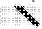
Fig. 9 :-45 ° of shop layer latticed material laying forming sketch mapes (form one);
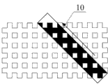
Figure 10: cut preimpregnation band (form two);
Figure 11 :-45 ° of shop layer latticed material laying forming sketch mapes (form two);
Label title among the figure: 1, put the roll coil of strip, 2, guide roller, 3, preimpregnation band to be cut, 4, backing paper, 5, two cutting knife; 6, collection guide roller, 7, waste material, 8, new backing paper, 9, hold-down roller; 10, cut the preimpregnation band, 11-1, take-up volume, the roll coil of strip is taken the lead to put in 11-2, shop, and 12, mould; 13, collection motor, 14, heater, 15, pressure roller or pressure shoes, 16, special backing film.
The specific embodiment
Composite automated tape-laying forming method with engraved structure mainly is applicable to the composite material laying moulding with engraved structure, like latticed member etc.The preimpregnation band precuts by reservation shape through two cutting knifes, when relating to low-angle cutting problem, can adopt staged broken line patterning method.The precut back of preimpregnation band adds new backing paper and rolling, takes the lead directly to carry out lay by the shop again, can accomplish the laying forming of the composite with engraved structure.
Further specify below in conjunction with Fig. 1,2,3,4,5,6,7,8,9 pairs of methods of the present invention, have two kinds of specific embodiment:
The specific embodiment one: combine Fig. 1,2,3,4,5,6,7,8 these embodiments of explanation.When having the composite material forming of engraved structure, at first design the preimpregnation belt shape, and then obtain the movement locus of two cutting knifes 5 according to geomery, preimpregnation band bandwidth and the shop layer direction of the moulding of wanting.Utilize precut device as shown in Figure 1, the preimpregnation band is precut.Preimpregnation band 3 to be cut is derived from putting the roll coil of strip 1 by guide roller 2, after backing paper 4 is peeled off, cuts into predetermined shape through two cutting knifes 5 again.Be guaranteed efficiency, realize producing continuously that two cutting knifes 5 need strict its depth of cut of control, when realizing the prepreg cutting and do not cut off backing paper.Prepreg adds new backing paper 8 (wherein one deck can replace with film) through after cutting, again by hold-down roller 9 compactings, and income take-up volume 11, this method is double-deck backing paper rolling method.On process precut the preimpregnation band lay and mould, principle is as shown in Figure 2 at last.Take-up volume 11 is assemblied in the shop takes the lead, become the shop and take the lead to put the roll coil of strip 11, receive backing paper roll 13 and peel off backing paper 4, after heater 14 carried out preheating simultaneously, 15 pairs of pressure roller or pressure shoes had cut preimpregnation band 10 and have exerted pressure, and make it fit in mould 12 surfaces.With the round-meshed member of lay is example; Like Fig. 3, consider low-angle cutting problem with regard to needs, promptly cutting knife running orbit and machine direction angle than hour; Because cut direction and preimpregnation band machine direction angulation are too small; The mobile meeting of cutting knife causes the fiber displacement and pile-up takes place, and then causes the gauffer of preimpregnation belt surface, influences the product surface smooth degree.Cutting knife running orbit in the Digit Control Machine Tool needs through planning in advance, its essence is the predetermined dog-leg path of the predetermined straight path composition of plurality of continuous.Therefore, at cutting angle hour, be generally less than 5 °, can the straight-line feed of cutting knife be changed into the broken line feeding, promptly adopt staged broken line patterning method.Like Fig. 4; Arrow is represented the machine direction in the preimpregnation band among the figure; Dotted line is represented a certain section predetermined straight path in the predetermined dog-leg path; Staged dog-leg path after solid line is represented to optimize, some A, B are respectively the starting point and the terminating point of this predetermined straight path, angle theta<5 of a certain section predetermined straight path machine direction ° and lsin θ>=b in predetermined dog-leg path Min(wherein, b MinExpression vertical fibers direction feeding minimum step; Be that cutting knife is when cutting in vertical direction; Can guarantee cut staple and not cause the minimum amount of feeding of fiber pile-up; L representes the length of the predetermined straight path AB of this section) time, adopt the staged polygometry that the predetermined straight path of this section is optimized earlier, carry out the cutting of preimpregnation band according to optimizing track again; Resulting optimization track is for being along machine direction feeding step-length with a, and b is the staged broken line of vertical fibers direction feeding step-length, and satisfies:
n = [ l sin θ b min ]
b = l sin θ n
a = b tan θ
Wherein, [] for rounding symbol downwards, n is the step-length number;
And when angle theta>5 of a certain section predetermined straight path in the predetermined dog-leg path and machine direction °, or θ<5 ° and lsin θ<b MinThe time, then be not optimized directly and the preimpregnation band cut into required form according to the predetermined straight path of this section;
The specific embodiment two: combine Fig. 5,6,7 these embodiments of explanation.With respect to embodiment one, this embodiment is identical on forming principle, and the preimpregnation band precut with laying method on difference to some extent, be individual layer backing paper rolling method.As shown in Figure 5, the preimpregnation band is after precuting, and the below adds the new backing paper 8 of one deck, and the top replaces with special backing film 16, and this backing paper can save one deck backing paper with preimpregnation band income take-up volume 11.During this preimpregnation band lay, as shown in Figure 6, can save a shop and take the lead collection motor 13, its sketch map such as Fig. 7.
The specific embodiment three: combine Fig. 8,9,10,11 these embodiments of explanation.And when relating to composite material laying moulding, be shaped to example with-45 ° of shop latticed material automated tape-layings of layer with a large amount of fenestral fabrics.Considered size of mesh opening and preimpregnation band bandwidth, the precut preimpregnation belt shape of design in advance.Carry out lay after the preimpregnation band precut into shape shown in Figure 9, molding effect is as shown in Figure 9, and wherein the arrow indication is a preimpregnation band lay direction, and black is represented the preimpregnation band, the mesh shape of white expression moulding.If the preimpregnation band precuts into shape shown in Figure 10, then molding effect is shown in figure 11.

Claims (2)

1.一种具有镂空结构的复合材料自动铺带成型方法,其特征包括以下过程:1. A composite material automatic tape-laying molding method with a hollow structure, characterized in that it comprises the following processes: 步骤1、首先根据制品形状尺寸、预浸带带宽及铺层方向设计好切割后预浸带形状,进而得到切刀的预定折线轨迹,预定折线轨迹由若干连续的预定直线轨迹组成;Step 1. First, design the shape of the prepreg tape after cutting according to the shape and size of the product, the width of the prepreg tape and the direction of the layup, and then obtain the predetermined broken line trajectory of the cutter. The predetermined broken line trajectory is composed of several continuous predetermined straight line trajectories; 步骤2、然后进行预切割,并进行带卷的收卷:Step 2. Then pre-cut and roll the tape: (2-1)、当预定折线轨迹中某一段预定直线轨迹与纤维方向的夹角θ<5°且lsinθ≥bmin时,先采用阶梯式折线法对该段预定直线轨迹进行优化,再根据优化轨迹进行预浸带的切割,其中bmin表示垂直纤维方向进给最小步长,即切刀在垂直方向上切割时,能够保证切断纤维且不引起纤维堆挤的最小进给量,l表示此段预定直线轨迹的长度;所得到的优化轨迹为以a为沿纤维方向进给步长,b为垂直纤维方向进给步长的阶梯式折线,并满足:(2-1) When the angle θ between a certain segment of the predetermined linear trajectory and the fiber direction in the predetermined broken line trajectory is <5° and lsinθ≥b min , first use the stepped broken line method to optimize the predetermined straight line trajectory of this section, and then according to Optimizing the trajectory to cut the prepreg tape, where b min represents the minimum step size of the vertical fiber direction, that is, when the cutter cuts in the vertical direction, the minimum feed rate that can ensure the cutting of fibers without causing fiber stacking, l represents The length of the predetermined linear trajectory in this section; the optimized trajectory obtained is a stepped broken line with a as the feed step along the fiber direction and b as the feed step perpendicular to the fiber direction, and satisfies: nno == [[ ll sinsin &theta;&theta; bb minmin ]] bb == ll sinsin &theta;&theta; nno aa == bb tanthe tan &theta;&theta; 其中,[]为向下取整符号,n为步长数;Among them, [] is the symbol of rounding down, and n is the number of steps; (2-2)、当预定折线轨迹中某一段预定直线轨迹与纤维方向的夹角θ≥5°时,或θ<5°且lsinθ<bmin时,则不进行优化直接根据该段预定直线轨迹将预浸带切割成所需形状;(2-2) When the angle θ between a certain section of the predetermined line trajectory and the fiber direction in the predetermined broken line trajectory is θ≥5°, or when θ<5° and lsinθ<b min , then do not optimize directly according to the predetermined straight line of this section Trajectory cuts the prepreg tape into the desired shape; 步骤3、最后由铺带头将已切割的预浸带铺放至模具表面,完成具有镂空结构的复合材料自动铺带成型。Step 3. Finally, the tape laying head lays the cut prepreg tape on the surface of the mold to complete the automatic tape laying of composite materials with a hollow structure. 2.根据权利要求1所述的复杂形状复合材料自动铺带成型方法,其特征在于:上述步骤2中所述进行带卷的收卷,具体采用双层背衬纸收卷方法或单层背衬纸收卷方法。2. The complex-shaped composite material automatic tape-laying forming method according to claim 1, characterized in that: the winding of the tape roll is carried out in the above-mentioned step 2, specifically adopting a double-layer backing paper winding method or a single-layer backing paper Lining paper winding method.
CN201110279636A 2011-09-20 2011-09-20 Automatic tape-laying forming method for composite material with hollowed-out structure Pending CN102310571A (en)

Priority Applications (1)

Application Number Priority Date Filing Date Title
CN201110279636A CN102310571A (en) 2011-09-20 2011-09-20 Automatic tape-laying forming method for composite material with hollowed-out structure

Applications Claiming Priority (1)

Application Number Priority Date Filing Date Title
CN201110279636A CN102310571A (en) 2011-09-20 2011-09-20 Automatic tape-laying forming method for composite material with hollowed-out structure

Publications (1)

Publication Number Publication Date
CN102310571A true CN102310571A (en) 2012-01-11

Family

ID=45424326

Family Applications (1)

Application Number Title Priority Date Filing Date
CN201110279636A Pending CN102310571A (en) 2011-09-20 2011-09-20 Automatic tape-laying forming method for composite material with hollowed-out structure

Country Status (1)

Country Link
CN (1) CN102310571A (en)

Cited By (9)

* Cited by examiner, † Cited by third party
Publication number Priority date Publication date Assignee Title
CN103722755A (en) * 2013-12-31 2014-04-16 中国航空工业集团公司北京航空制造工程研究所 Guide device for composite material prepreg tape for tape paving machine
CN103722752A (en) * 2013-12-31 2014-04-16 中国航空工业集团公司北京航空制造工程研究所 Composite material prepreg tape laying mechanism with pressure detection device
CN104626611A (en) * 2015-01-30 2015-05-20 武汉大学 Six-shaft robot-based type automatic tape paving device and six-shaft robot based type automatic tape paving method
CN105172160A (en) * 2015-07-14 2015-12-23 哈尔滨工业大学 Preparing method for composite material periodic truss structure
CN108375956A (en) * 2018-03-13 2018-08-07 南京航空航天大学 Double end lays post-processing approach
CN109367072A (en) * 2018-10-08 2019-02-22 南京航空航天大学 A kind of multi-directional prepreg tape preparation device and preparation method thereof
CN112590253A (en) * 2020-11-30 2021-04-02 浙江大学 Backing tape supporting device for laying thermosetting composite material prepreg tape
CN116352777A (en) * 2023-05-11 2023-06-30 通用技术齐齐哈尔二机床有限责任公司 An ultrasonic cutting device for special-shaped cross-sections of an automatic tape laying machine
CN117325483A (en) * 2023-10-26 2024-01-02 浙江大学 Laser in-situ material increasing and decreasing composite forming equipment and method for composite material member

Citations (4)

* Cited by examiner, † Cited by third party
Publication number Priority date Publication date Assignee Title
US5041179A (en) * 1988-05-24 1991-08-20 Shinnippon Koki Kabushiki Kaisha Method for controlling tape affixing direction of automatic tape affixing apparatus
CN1618598A (en) * 2003-11-21 2005-05-25 米其林研究和技术股份有限公司 Method of continuously laying strips on a complex curved surface
US20060073309A1 (en) * 2004-10-05 2006-04-06 The Boeing Company Method for laying composite tape
CN101419446A (en) * 2008-11-26 2009-04-29 南京航空航天大学 Composite material laying track micro diameter-changing self-regulating method

Patent Citations (4)

* Cited by examiner, † Cited by third party
Publication number Priority date Publication date Assignee Title
US5041179A (en) * 1988-05-24 1991-08-20 Shinnippon Koki Kabushiki Kaisha Method for controlling tape affixing direction of automatic tape affixing apparatus
CN1618598A (en) * 2003-11-21 2005-05-25 米其林研究和技术股份有限公司 Method of continuously laying strips on a complex curved surface
US20060073309A1 (en) * 2004-10-05 2006-04-06 The Boeing Company Method for laying composite tape
CN101419446A (en) * 2008-11-26 2009-04-29 南京航空航天大学 Composite material laying track micro diameter-changing self-regulating method

Non-Patent Citations (2)

* Cited by examiner, † Cited by third party
Title
李勇等: "复合材料锥壳螺旋向铺层自动铺带成型方法", 《宇航材料工艺》 *
还大军等: "基于弧长的复合材料自动铺带统一边界处理方法", 《南京航空航天大学学报》 *

Cited By (15)

* Cited by examiner, † Cited by third party
Publication number Priority date Publication date Assignee Title
CN103722755A (en) * 2013-12-31 2014-04-16 中国航空工业集团公司北京航空制造工程研究所 Guide device for composite material prepreg tape for tape paving machine
CN103722752A (en) * 2013-12-31 2014-04-16 中国航空工业集团公司北京航空制造工程研究所 Composite material prepreg tape laying mechanism with pressure detection device
CN103722755B (en) * 2013-12-31 2016-02-24 中国航空工业集团公司北京航空制造工程研究所 A kind of guider of the composite material prepreg for belt spreading machine
CN103722752B (en) * 2013-12-31 2016-03-09 中国航空工业集团公司北京航空制造工程研究所 There is the composite material prepreg laying mechanism of pressure-detecting device
CN104626611A (en) * 2015-01-30 2015-05-20 武汉大学 Six-shaft robot-based type automatic tape paving device and six-shaft robot based type automatic tape paving method
CN105172160A (en) * 2015-07-14 2015-12-23 哈尔滨工业大学 Preparing method for composite material periodic truss structure
CN108375956A (en) * 2018-03-13 2018-08-07 南京航空航天大学 Double end lays post-processing approach
CN109367072A (en) * 2018-10-08 2019-02-22 南京航空航天大学 A kind of multi-directional prepreg tape preparation device and preparation method thereof
CN109367072B (en) * 2018-10-08 2024-01-16 南京航空航天大学 A multi-directional prepreg tape preparation device and its preparation method
CN112590253A (en) * 2020-11-30 2021-04-02 浙江大学 Backing tape supporting device for laying thermosetting composite material prepreg tape
CN112590253B (en) * 2020-11-30 2021-09-28 浙江大学 Backing tape supporting device for laying thermosetting composite material prepreg tape
CN116352777A (en) * 2023-05-11 2023-06-30 通用技术齐齐哈尔二机床有限责任公司 An ultrasonic cutting device for special-shaped cross-sections of an automatic tape laying machine
CN116352777B (en) * 2023-05-11 2026-04-07 通用技术齐齐哈尔二机床有限责任公司 An ultrasonic cutting device for irregular cross-sections of an automatic tape laying machine
CN117325483A (en) * 2023-10-26 2024-01-02 浙江大学 Laser in-situ material increasing and decreasing composite forming equipment and method for composite material member
CN117325483B (en) * 2023-10-26 2024-05-03 浙江大学 Laser in-situ additive and subtractive composite forming equipment and method for composite material components

Similar Documents

Publication Publication Date Title
CN102310571A (en) Automatic tape-laying forming method for composite material with hollowed-out structure
JP2023027359A (en) Intermittently fiber-separated continuous carbon fiber bundle and manufacturing method thereof
US4519285A (en) Cutting method and apparatus for tape laying machines
JP2021102784A5 (en)
CN103586938A (en) Method for producing gapped adhesive tape
JP2010027227A (en) Method for manufacturing electrolyte membrane for fuel cell electrode
CN106905864A (en) A kind of processing method of the macromolecular material adhesive tape for electronic product display
CN110421955B (en) Process for manufacturing nanocrystalline double-covered edges by using roller cutter
CN217891195U (en) Asynchronous die cutting system
CN102407650A (en) Forming method and device for composite material 0-degree layering
CN206501179U (en) It is a kind of to be die cut the tool that slitting is molded simultaneously
CN112537040A (en) Multilayer structure product and die cutting process thereof
JPH04344225A (en) Automatic laminating apparatus for composite material
CN204211680U (en) The double faced adhesive tape organisation of working of electrode slice apparatus for production line
JP4770678B2 (en) Manufacturing method and apparatus for sheet wrapping product
CN208853575U (en) A kind of stamping equipment of automatic material receiving
CN203622559U (en) Production device with interval adhesive tape
CN202668629U (en) Rip cutting creasing machine of corrugated board for quickly changing boards
CN101450534A (en) Composite material laying one-step material-removing method
CN211807982U (en) Double-asynchronous device for silk screen products
CN207155989U (en) Accurately go out device for mark
CN202337606U (en) Adhesive paper traction device for battery positive electrode sheet making machine
US9085116B2 (en) Method for manufacturing honeycomb structure
CN203752244U (en) Straight knife die cutting system for processing paper substrate die cutting piece
CN202378108U (en) Vertical concurrent heating mechanism for thermal die-cutting machine

Legal Events

Date Code Title Description
C06 Publication
PB01 Publication
C10 Entry into substantive examination
SE01 Entry into force of request for substantive examination
C02 Deemed withdrawal of patent application after publication (patent law 2001)
WD01 Invention patent application deemed withdrawn after publication

Application publication date: 20120111