CN102264996A - Expanding a tubular element in a wellbore - Google Patents
Expanding a tubular element in a wellbore Download PDFInfo
- Publication number
- CN102264996A CN102264996A CN2009801520034A CN200980152003A CN102264996A CN 102264996 A CN102264996 A CN 102264996A CN 2009801520034 A CN2009801520034 A CN 2009801520034A CN 200980152003 A CN200980152003 A CN 200980152003A CN 102264996 A CN102264996 A CN 102264996A
- Authority
- CN
- China
- Prior art keywords
- segments
- tubular element
- radially
- expansion member
- expansion
- Prior art date
- Legal status (The legal status is an assumption and is not a legal conclusion. Google has not performed a legal analysis and makes no representation as to the accuracy of the status listed.)
- Pending
Links
Images


Classifications
-
- E—FIXED CONSTRUCTIONS
- E21—EARTH OR ROCK DRILLING; MINING
- E21B—EARTH OR ROCK DRILLING; OBTAINING OIL, GAS, WATER, SOLUBLE OR MELTABLE MATERIALS OR A SLURRY OF MINERALS FROM WELLS
- E21B43/00—Methods or apparatus for obtaining oil, gas, water, soluble or meltable materials or a slurry of minerals from wells
- E21B43/02—Subsoil filtering
- E21B43/10—Setting of casings, screens, liners or the like in wells
- E21B43/103—Setting of casings, screens, liners or the like in wells of expandable casings, screens, liners, or the like
- E21B43/105—Expanding tools specially adapted therefor
-
- E—FIXED CONSTRUCTIONS
- E21—EARTH OR ROCK DRILLING; MINING
- E21B—EARTH OR ROCK DRILLING; OBTAINING OIL, GAS, WATER, SOLUBLE OR MELTABLE MATERIALS OR A SLURRY OF MINERALS FROM WELLS
- E21B23/00—Apparatus for displacing, setting, locking, releasing or removing tools, packers or the like in boreholes or wells
- E21B23/04—Apparatus for displacing, setting, locking, releasing or removing tools, packers or the like in boreholes or wells operated by fluid means, e.g. actuated by explosion
- E21B23/0411—Apparatus for displacing, setting, locking, releasing or removing tools, packers or the like in boreholes or wells operated by fluid means, e.g. actuated by explosion specially adapted for anchoring tools or the like to the borehole wall or to well tube
-
- E—FIXED CONSTRUCTIONS
- E21—EARTH OR ROCK DRILLING; MINING
- E21B—EARTH OR ROCK DRILLING; OBTAINING OIL, GAS, WATER, SOLUBLE OR MELTABLE MATERIALS OR A SLURRY OF MINERALS FROM WELLS
- E21B23/00—Apparatus for displacing, setting, locking, releasing or removing tools, packers or the like in boreholes or wells
- E21B23/04—Apparatus for displacing, setting, locking, releasing or removing tools, packers or the like in boreholes or wells operated by fluid means, e.g. actuated by explosion
- E21B23/042—Apparatus for displacing, setting, locking, releasing or removing tools, packers or the like in boreholes or wells operated by fluid means, e.g. actuated by explosion using a single piston or multiple mechanically interconnected pistons
-
- E—FIXED CONSTRUCTIONS
- E21—EARTH OR ROCK DRILLING; MINING
- E21B—EARTH OR ROCK DRILLING; OBTAINING OIL, GAS, WATER, SOLUBLE OR MELTABLE MATERIALS OR A SLURRY OF MINERALS FROM WELLS
- E21B43/00—Methods or apparatus for obtaining oil, gas, water, soluble or meltable materials or a slurry of minerals from wells
- E21B43/02—Subsoil filtering
- E21B43/10—Setting of casings, screens, liners or the like in wells
- E21B43/103—Setting of casings, screens, liners or the like in wells of expandable casings, screens, liners, or the like
Landscapes
- Geology (AREA)
- Life Sciences & Earth Sciences (AREA)
- Engineering & Computer Science (AREA)
- Mining & Mineral Resources (AREA)
- Environmental & Geological Engineering (AREA)
- Fluid Mechanics (AREA)
- Physics & Mathematics (AREA)
- General Life Sciences & Earth Sciences (AREA)
- Geochemistry & Mineralogy (AREA)
- Earth Drilling (AREA)
- Pistons, Piston Rings, And Cylinders (AREA)
- Joints Allowing Movement (AREA)
- Shaping Of Tube Ends By Bending Or Straightening (AREA)
Abstract
Description
背景技术 Background technique
本发明涉及一种使用位于管状元件中的扩张器来使井眼中的管状元件径向扩张的方法。井眼中的管状元件(诸如套管或衬管)的扩张日益增加地应用于从大地地层中开采油和气的工业中,由此,钻出一个或多个钻孔以从地下储层向位于地面的生产设备产出烃流体。传统地,这种钻孔在钻出钻孔期间在不同深度处设置有若干套管。每根随后的套管必须通过之前已经安装的套管,所以,这些套管在向下的方向上具有减小的直径,这形成了套管的嵌套布置。因而,用于烃流体生产的有效井眼直径随着深度而减小。这尤其是对于具有较多数量套管的深井来说可导致技术缺陷和/或经济缺陷。The present invention relates to a method of radially expanding a tubular element in a wellbore using an expander located in the tubular element. Expansion of tubular elements, such as casing or liners, in wellbores is increasingly used in the industry for the recovery of oil and gas from subterranean formations, whereby one or more boreholes are drilled to pass from a subterranean reservoir to a surface located at the surface. The production facility produces hydrocarbon fluids. Traditionally, such boreholes are provided with several casings at different depths during drilling of the borehole. Each subsequent bushing must pass through the previously installed bushings, so these bushes have a decreasing diameter in the downward direction, which forms a nested arrangement of the bushings. Thus, the effective wellbore diameter for hydrocarbon fluid production decreases with depth. This can lead to technical and/or economical disadvantages, especially for deep wells with a greater number of casings.
为了克服这些缺陷,已经提出使用套管方案,由此,各套管在安装于井眼中之后被径向扩张。这种套管方案使得有效井眼直径随着深度的减小而较小。通常而言,这种管状元件在将管状元件下入井眼中之后通过拉动、泵送或推动圆锥形扩张器通过管状元件而径向扩张。然而,用于使扩张器运动通过管状元件所必需的扩张力有时极高,这是因为这种力不仅必须使管状元件扩张,而且必须克服扩张器锥体与管状元件之间的摩擦。In order to overcome these disadvantages, casing solutions have been proposed, whereby each casing is radially expanded after being installed in the wellbore. This casing scheme results in a smaller effective borehole diameter with decreasing depth. Typically, such tubular elements are radially expanded after running the tubular element into the wellbore by pulling, pumping or pushing a conical expander through the tubular element. However, the expansion force necessary to move the dilator through the tubular element is sometimes extremely high since such force must not only expand the tubular element but also overcome the friction between the dilator cone and the tubular element.
EP 1618280B1公开了一种使用位于管状元件中的扩张器来使井眼中的管状元件径向扩张的方法,该扩张器包括多个部段,该多个部段绕着具有流体腔室的囊状物在圆周方向上间隔开。该管状元件以多个循环进行扩张,由此,在每个循环中,通过将流体泵送到流体腔室中以使得囊状物扩张且扩张器进行扩张冲程,多个部段从径向缩回位置运动到径向扩张位置。EP 1618280B1 discloses a method of radially expanding a tubular element in a wellbore using a dilator located in the tubular element, the expander comprising a plurality of sections surrounding a bladder having a fluid chamber are spaced apart in the circumferential direction. The tubular element is expanded in cycles whereby, in each cycle, the segments are radially retracted by pumping fluid into the fluid chamber to expand the balloon and the dilator performs an expansion stroke. Back position moves to radially expanded position.
在一些应用中,已经经历的是,多个部段可能不总是均匀地扩张,并且囊状物在重复的扩张循环之后被损坏。In some applications, it has been experienced that the segments may not always expand uniformly and the bladder becomes damaged after repeated expansion cycles.
US-2003/0111234-A1公开了一种用于使管状衬管扩张的扩张系统。该系统包括扩张装置,该扩张装置包括具有多个部段的心轴,所述多个部段在收缩状态与扩张状态之间运动。当处于扩张状态时,心轴被推动或拉动通过管状衬管,以使该管状衬管扩张。US-2003/0111234-A1 discloses an expansion system for expanding a tubular liner. The system includes an expansion device including a mandrel having a plurality of sections that move between a contracted state and an expanded state. When in the expanded state, the mandrel is pushed or pulled through the tubular liner to expand the tubular liner.
WO 03/036025-A1公开了一种用于为井眼嵌衬可扩张的管状元件的系统。该系统包括扩张锥和锚定装置,该扩张锥布置在延伸到井眼中的柱的下端部处,该锚定装置将管状元件的上端部锚定在井眼中。一旦管状元件被锚定,扩张锥被推动通过管状元件,以使该管状元件扩张。WO 03/036025-A1 discloses a system for lining a wellbore with expandable tubular elements. The system includes an expansion cone disposed at the lower end of the string extending into the wellbore and an anchoring device that anchors the upper end of the tubular element in the wellbore. Once the tubular element is anchored, the expansion cone is pushed through the tubular element to expand the tubular element.
上述系统包括被拉动或推动通过管状元件的扩张器。因此,这些系统使管状元件扩张到扩张器锥体的直径,但是缺乏适应井眼直径的局部变化的可能性。The systems described above include a dilator that is pulled or pushed through a tubular member. Thus, these systems expand the tubular element to the diameter of the expander cone, but lack the possibility to accommodate local variations in borehole diameter.
发明内容 Contents of the invention
本发明的一个目的是提供一种使管状元件径向扩张以抵靠在井眼中的壁上的改进方法,该方法克服了已知方法的缺陷。It is an object of the present invention to provide an improved method of radially expanding a tubular element against a wall in a wellbore which overcomes the disadvantages of known methods.
根据本发明,提供了一种使用位于管状元件中的扩张器来使井眼中的管状元件径向扩张的方法,该扩张器包括扩张构件和围绕该扩张构件在圆周方向上间隔开的多个部段,该多个部段通过扩张构件相对于多个部段的轴向运动可在径向缩回位置与径向扩张位置之间运动,该方法包括多个扩张循环,其中每个扩张循环包括以下步骤:In accordance with the present invention there is provided a method of radially expanding a tubular element in a wellbore using an expander located in the tubular element, the expander comprising an expanding member and a plurality of portions circumferentially spaced around the expanding member. segments movable between radially retracted positions and radially expanded positions by axial movement of an expansion member relative to the plurality of segments, the method comprising a plurality of expansion cycles, wherein each expansion cycle comprises The following steps:
(a)使扩张器在轴向向前的方向上运动通过管状元件,由此,该多个部段处于径向缩回位置;以及(a) moving the dilator through the tubular element in an axially forward direction whereby the segments are in a radially retracted position; and
(b)通过使扩张构件相对于多个部段轴向运动而使多个部段运动到径向扩张位置,从而使管状元件扩张。(b) expanding the tubular element by moving the plurality of segments to a radially expanded position by axially moving the expansion member relative to the plurality of segments.
由此,不再需要用于使多个部段扩张的囊状物。另外,通过使扩张构件相对于多个部段轴向运动保证了多个部段均匀地扩张。此外,由于相继的扩张循环,本发明的扩张方法可适应于井眼直径的局部变化。Thereby, bladders for expanding the segments are no longer required. Additionally, axial movement of the expansion member relative to the segments ensures uniform expansion of the segments. Furthermore, the expansion method of the present invention can accommodate local variations in borehole diameter due to successive expansion cycles.
适当地,每个部段和扩张构件具有楔形的共同接触表面,以便在扩张构件相对于部段在第一轴向方向上的运动时引起部段的径向向外运动,以及在扩张构件相对于部段在与第一轴向方向相反的第二轴向方向上的运动时引起部段的径向向内运动。Suitably, each segment and expansion member have a common contact surface that is wedge-shaped so as to induce radially outward movement of the segment upon movement of the expansion member relative to the segment in a first axial direction, and The radially inward movement of the segment is induced upon movement of the segment in a second axial direction opposite the first axial direction.
多个部段从缩回位置到扩张位置的运动限定出扩张冲程。为了以顺从的模式使管状元件扩张,由此使管状元件扩张,以使得管状元件的形状在扩张之后符合围绕管状元件的边界壁的形状,或者使得考虑管状元件的壁厚变化,本方法优选地包括多个相继的扩张循环,由此,变化相应扩张冲程的幅度。Movement of the plurality of segments from the retracted position to the expanded position defines an expansion stroke. In order to expand the tubular element in a compliant mode, thereby expanding the tubular element such that the shape of the tubular element conforms to the shape of a boundary wall surrounding the tubular element after expansion, or so as to account for variations in wall thickness of the tubular element, the method preferably A number of successive expansion cycles are involved, whereby the amplitude of the respective expansion strokes is varied.
例如,管状元件被径向扩张以抵靠在具有变化直径的井眼的壁上,并且相应扩张冲程的幅度与壁的所述变化直径相一致地改变。扩张致动器的轴向运动限定致动器的冲程,优选的是,多个部段的扩张冲程的幅度通过改变扩张构件的致动冲程的幅度而改变。For example, the tubular element is radially expanded to bear against the wall of a wellbore having a varying diameter, and the magnitude of the corresponding expansion stroke changes in line with said varying diameter of the wall. Axial movement of the expansion actuator defines a stroke of the actuator, preferably the magnitude of the expansion stroke of the segments is varied by varying the magnitude of the actuation stroke of the expansion member.
在一个优选实施例中,管状元件在分开的扩张段中被扩张,其中,多个部段包括第一组部段和第二组部段。第二组部段布置在相对于第一组部段的后续位置中,由此,在径向扩张位置中,该第二组部段具有比第一组部段大的直径。在步骤(b)中,管状元件通过第一组部段被扩张到第一直径,通过第二组部段被扩张到第二直径,第二直径大于第一直径。In a preferred embodiment, the tubular element is expanded in separate expansion segments, wherein the plurality of segments comprises a first set of segments and a second set of segments. The segments of the second group are arranged in a subsequent position relative to the segments of the first group whereby, in the radially expanded position, the segments of the second group have a larger diameter than the segments of the first group. In step (b), the tubular element is expanded to a first diameter by a first set of segments and by a second set of segments to a second diameter, the second diameter being greater than the first diameter.
适当地,扩张器包括液压致动器,该液压致动器可操作以引起扩张构件的所述轴向运动。Suitably, the dilator includes a hydraulic actuator operable to cause said axial movement of the dilation member.
优选的是,液压致动器与液压流体供给管道流体连通,并且扩张器在液压流体供给管道上悬挂于井眼中。液压流体供给管道例如是钻杆或盘管。Preferably, the hydraulic actuator is in fluid communication with the hydraulic fluid supply conduit and the expander is suspended in the wellbore on the hydraulic fluid supply conduit. The hydraulic fluid supply conduit is, for example, drill pipe or coiled tubing.
扩张构件适当地经受交替的轴向运动,以使多个部段在径向缩回位置与径向扩张位置之间交替运动,其中液压致动器包括阀系统,该阀系统可操作以引起扩张构件的所述交替运动。The expansion member is suitably subjected to alternating axial movement to alternately move the segments between radially retracted positions and radially expanded positions, wherein the hydraulic actuator includes a valve system operable to cause expansion The alternating movement of the components.
附图说明Description of drawings
以下将参照所附的附图通过举例的方式更详细地描述本发明,附图中:The invention will be described in more detail below by way of example with reference to the accompanying drawings, in which:
图1以纵截面的方式示意性地示出了用于本发明的方法中的扩张器的一个实施例;Fig. 1 shows schematically an embodiment of the dilator used in the method of the present invention in a longitudinal section;
图2以纵截面的方式示意性地示出了用于本发明的方法中的一种可替代的扩张器;Fig. 2 shows schematically an alternative dilator for use in the method of the present invention in longitudinal section;
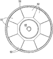
图3示出了图2的横截面3-3,其中扩张器处于径向缩回位置;Figure 3 shows the cross-section 3-3 of Figure 2 with the dilator in a radially retracted position;
图4示出了图2的横截面3-3,其中扩张器处于径向扩张位置;Figure 4 shows the cross-section 3-3 of Figure 2 with the dilator in a radially expanded position;
图5示意性地示出了图2的扩张器的改进型;Figure 5 schematically shows a modification of the dilator of Figure 2;
图6以纵截面的方式示意性地示出了用于本发明的方法中的另一种可替代的扩张器,该扩张器处于径向缩回位置;Figure 6 schematically shows in longitudinal section another alternative dilator for use in the method of the present invention, in a radially retracted position;
图7示出了处于径向扩张位置时的图6中的扩张器;Figure 7 shows the dilator of Figure 6 in a radially expanded position;
图8示意性地示出了用于本发明的方法中的液压控制系统,该液压控制系统处于第一操作模式;Figure 8 schematically illustrates a hydraulic control system used in the method of the present invention, the hydraulic control system being in a first mode of operation;
图9示出了当处于第二操作模式时图8的液压控制系统;Figure 9 shows the hydraulic control system of Figure 8 when in the second mode of operation;
图10示意性地示出了用于本发明的方法中的一种可替代的液压控制系统,该液压控制系统处于第一操作模式;以及Figure 10 schematically illustrates an alternative hydraulic control system for use in the method of the present invention, the hydraulic control system being in a first mode of operation; and
图11示出了处于第二操作模式时的图10的液压控制系统。Figure 11 shows the hydraulic control system of Figure 10 in a second mode of operation.
在这些附图中,相同的附图标记标识相同的部件。In the figures, the same reference numerals identify the same parts.
具体实施方式 Detailed ways
参照图1,示出了形成于大地地层2中的井眼1,其中可扩张的管状元件4在径向扩张以抵靠井眼壁6之前位于井眼1中。扩张器10延伸进入井眼中,该扩张器包括一组部段18,该组部段围绕着扩张构件20圆周地间隔开。点线22表示所示系统的中心纵向轴线。多个部段可相对于中心纵向轴线22径向运动,并且该扩张构件20可相对于多个部段18轴向运动。扩张构件20具有向上渐缩的外表面24,而且每个部段18具有与该扩张构件的渐缩的外表面24接触的内表面26,其中表面24、26基本上是形状互补的。依靠这种构造,多个部段18在扩张构件20轴向向上运动时径向向外运动,而多个部段18在扩张构件20轴向向下运动时径向向内运动。扩张器10可在径向扩张模式与径向缩回模式之间运动,由此,多个部段18在径向扩张模式中处于径向最外位置,而多个部段18在径向缩回模式中处于径向最内位置。在径向缩回模式中,这组部段18的下部部分配合在未扩张的管状元件4的内部,而这组部段18的上部部分具有比未扩张的管状元件4的内直径大的直径。此外,在径向扩张模式中,扩张器使管状元件4扩张以抵靠井眼壁6。Referring to FIG. 1 , there is shown a wellbore 1 formed in a
扩张构件20连接至液压致动器28,该液压致动器可操作以使扩张构件20相对于多个部段18轴向向上或向下运动。液压流体经由从地面延伸到扩张器10的盘管柱29供给到该液压致动器28。替代盘管柱的是,可使用任何其它适当的钻具,例如由联接好的钻杆构成的柱。The expansion member 20 is connected to a hydraulic actuator 28 operable to move the expansion member 20 axially upward or downward relative to the plurality of segments 18 . Hydraulic fluid is supplied to the hydraulic actuator 28 via a coil string 29 extending from the surface to the expander 10 . Instead of a coiled string, any other suitable drilling tool may be used, such as a string of coupled drill pipe.
扩张器10还包括锚定装置30,该锚定装置包括可在径向缩回位置与径向扩张位置之间运动的锚31,在径向缩回位置中,锚31从管状元件4的内表面32脱开,在径向扩张位置中,锚31固定地连接到内表面32。锚定装置30还包括液压悬挂致动器34,该液压悬挂致动器通过轴35连接到扩张构件,并且可操作以使锚31相对于扩张构件20在轴向方向上运动。通过经由盘管柱29供给的液压流体从地面控制悬挂致动器34。The dilator 10 also includes an anchoring device 30 comprising an anchor 31 movable between a radially retracted position and a radially expanded position in which the anchor 31 is released from the inner portion of the tubular element 4. The surface 32 is disengaged and the anchor 31 is fixedly connected to the inner surface 32 in the radially expanded position. The anchoring device 30 also includes a hydraulic suspension actuator 34 connected to the expansion member by a shaft 35 and operable to move the anchor 31 in an axial direction relative to the expansion member 20 . The suspension actuator 34 is controlled from the surface by hydraulic fluid supplied via the coil string 29 .
参照图2-4,示出了用于本发明的方法中的一种可替代的扩张器40。扩张器40包括具有环形腔室44和环形狭隙46的圆筒形壳体42,该环形狭隙从腔室44延伸到扩张器40的外表面。以扩张构件48可在腔室44中轴向运动的方式将具有渐缩的外表面49的环形扩张构件48定位于腔室44中。另外,扩张器包括多个部段50,该多个部段绕着扩张构件48在圆周方向上间隔开,由此,多个部段50经过环形狭隙46并且可在径向缩回位置与径向扩张位置之间运动。每个部段50均具有渐缩的内表面52,该渐缩的内表面与扩张构件48的渐缩的外表面49接触,以使得该部段50在扩张构件48在箭头54的方向上轴向运动时径向向外运动。相反地,该部段50在扩张构件48在与箭头54相反的方向上轴向运动时径向向内运动。扩张器40定位于可扩张的管状元件56中,该可扩张的管状元件延伸到形成于大地地层60中的井眼59中。Referring to Figures 2-4, an
在图3和4中,示出了扩张器40的横截面图,由此,在图3中,多个部段50处于径向缩回位置,而在图4中,多个部段50处于径向扩张位置,其中在相邻的部段50之间存在小的间隙62。In FIGS. 3 and 4, a cross-sectional view of the
进一步参照图5,图5示出了改进的扩张器64,该扩张器基本上类似于扩张器40,只是部段50具有弯曲的外表面66,以便在利用扩张器64扩张时形成管状元件中的波状轮廓。With further reference to FIG. 5 , there is shown a modified
进一步参照图6和图7,示出了用于本发明的方法中的另一可替代的扩张器70。扩张器70包括呈楔形件72形式的第一扩张构件以及呈楔形件74形式的第二扩张构件,楔形件72、74朝向彼此渐缩。液压致动器76布置成借助于连接至液压致动器的活塞77的拉杆78在箭头77方向上拉动楔形件72。楔形件74与液压致动器76的壳体80邻接。第一组部段80围绕楔形件72圆周地间隔开,并与楔形件72的渐缩的表面接触,而第二组部段84围绕楔形件74圆周地间隔开,并与楔形件74的渐缩的表面接触。部段82、84可在缩回位置与扩张位置之间径向运动,并且间隔圆筒85与第一组部段82和第二组部段84相互连接。部段84比部段82更进一步地径向向外延伸,以便在部段82、84位于径向扩张位置时,第二组部段84具有比第一组部段82大的外直径。第二组部段84设置有卡爪86,该卡爪与连接到拉杆78的环88邻靠,从而在扩张器的扩张冲程期间限制第二组部段84的轴向运动。另外,楔形件72、74在它们的较大直径端部处设置有相应的端部止挡90、92。With further reference to Figures 6 and 7, another
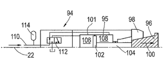
参照图8、9,示出了扩张器以及用于控制扩张器的液压致动器95的液压控制系统94。扩张器包括楔形件96和一组部段98,这组部段98绕着楔形件96圆周地间隔开,并且与楔形件96的渐缩的表面接触。部段98在楔形件96在箭头99方向上运动时运动到径向扩张位置,而在楔形件96在箭头100方向上运动时运动到径向缩回位置。液压致动器95包括活塞/缸组件101,该活塞/缸组件具有通过拉杆104连接到楔形件96的活塞102。活塞/缸组件101在活塞102的相对侧处具有相应的流体腔室106、108,由此,流体腔室108位于拉杆102侧。另外,鉴于腔室108中存在拉杆102,活塞102在腔室108侧具有比在腔室106侧小的液压面积。Referring to Figures 8 and 9, there is shown a dilator and a
液压控制系统94包括流体供给管线110,该流体供给管线提供流体腔室108与位于地面的泵(未示出)之间的流体连通。三通阀112布置成在第一操作模式下提供流体腔室106与井眼内部之间的流体连通。在第二操作模式中,三通阀112提供流体腔室106与流体供给管线110之间的流体连通。流体积聚器114设置用于吸收流体供给管线110中的压力峰值。The
参照图10、11,示出了一种可替代的液压控制系统116,其基本上类似于控制系统94,只是使用四通阀116来代替三通阀。在第一操作模式中,四通阀116提供流体供给管线110与流体腔室108之间的流体连通,与此同时还提供流体腔室106与周围环境之间的流体连通。在第二操作模式中,四通阀116提供流体供给管线110与流体腔室106之间的流体连通,与此同时还提供流体腔室108与周围环境之间的流体连通。Referring to Figures 10 and 11, an alternative
在图1系统的正常使用期间,在第一步骤中,锚定装置30位于管状元件4的内部,其中,锚31处于径向缩回位置中,并且扩张器10位于管状元件4上方。锚31然后被引导以运动到径向扩张位置,从而固定地连接到管状元件4。扩张组件8以及从扩张组件8悬挂下来的管状元件4然后在盘管柱29上被下入井眼中。During normal use of the system of FIG. 1 , in a first step, the anchoring device 30 is located inside the tubular element 4 , with the anchor 31 in the radially retracted position and the dilator 10 above the tubular element 4 . The anchor 31 is then guided to move into a radially expanded position, thereby being fixedly connected to the tubular element 4 . The expansion assembly 8 and the tubular element 4 suspended from the expansion assembly 8 are then lowered into the wellbore on the coil string 29 .
在第二步骤中,在扩张器处于径向缩回模式的情况下,从地面液压控制悬挂致动器34以使锚31以及与锚连接的管状元件4的轴向向上运动,直到多个部段18部分地位于管状元件4中且管状元件4停靠在扩张器的多个部段18上。然后,控制悬挂致动器34以使得管状元件4保持压靠在多个部段18上。In a second step, with the expander in the radially retracted mode, the suspension actuator 34 is hydraulically controlled from the surface to move the anchor 31 and the tubular element 4 connected to the anchor axially upwards until a plurality of sections The segments 18 are partly located in the tubular element 4 and the tubular element 4 rests on the segments 18 of the dilator. The suspension actuator 34 is then controlled such that the tubular element 4 remains pressed against the segments 18 .
在第三步骤中,控制多级活塞/缸组件28以使扩张致动器20轴向向上运动,从而使多个部段18径向向外运动,同时管状元件4通过悬挂致动器34保持压靠在多个部段18上。结果,管状元件4的上部部分径向扩张以抵靠在井眼壁6上。在第四步骤中,控制活塞/缸组件28以使扩张致动器20轴向向下运动,以使得多个部段18径向缩回。在多个部段18径向缩回的情况下,该扩张器10轴向向下运动,直到部段18停靠在管状元件4的未扩张部分的内表面上。通过重力进行扩张器10的这种轴向向下运动,必要时,通过操作悬挂致动器34向下拉动扩张器10来进行扩张器10的这种轴向向下运动。In a third step, the multistage piston/cylinder assembly 28 is controlled to move the expansion actuator 20 axially upward, thereby moving the segments 18 radially outward, while the tubular element 4 is held by the suspension actuator 34. Pressed against the segments 18 . As a result, the upper part of the tubular element 4 expands radially to bear against the borehole wall 6 . In a fourth step, the piston/cylinder assembly 28 is controlled to move the expansion actuator 20 axially downwards so that the segments 18 are radially retracted. With the segments 18 radially retracted, the dilator 10 is moved axially downwards until the segments 18 rest on the inner surface of the unexpanded portion of the tubular element 4 . This axial downward movement of the dilator 10 is performed by gravity and, if necessary, by operating the suspension actuator 34 to pull the dilator 10 downward.
重复进行第三步骤和第四步骤足够多次数,直到管状元件固定地连接到井眼壁6,以使得锚定装置不再需要悬挂管状元件4。The third and fourth steps are repeated a sufficient number of times until the tubular element is fixedly connected to the wellbore wall 6 so that the anchoring means no longer need to suspend the tubular element 4 .
在第五步骤中,锚31从管状元件4的内表面32径向缩回。之后,重复进行第三步骤和第四步骤,直到整个管状元件4已经径向扩张以抵靠在井眼壁6上。为了取回扩张组件8,扩张器10被带入径向缩回模式,并且通过已扩张的管状元件4将扩张组件8取回到地面。In a fifth step, the anchor 31 is radially retracted from the inner surface 32 of the tubular element 4 . Thereafter, the third and fourth steps are repeated until the entire tubular element 4 has been radially expanded to rest against the borehole wall 6 . To retrieve the expansion assembly 8, the dilator 10 is brought into a radially retracted mode, and the expansion assembly 8 is retrieved to the surface through the expanded tubular element 4 .
对图2-4系统的正常使用基本上类似于对图1系统的正常使用,虽然扩张构件48在扩张冲程期间是被推动而不是拉动,以使多个部段50从径向缩回位置运动到径向扩张位置。多个部段50在扩张构件48在方向54上运动时径向向外运动,而在扩张构件48在相反的方向上运动时径向向内运动。Normal use of the system of Figures 2-4 is substantially similar to normal use of the system of Figure 1, although the
对图5系统的正常使用基本上类似于对图2-4系统的正常使用。此处,该组部段50的弯曲外表面66产生了管状元件56中的波状轮廓,从而增加了管状元件56的抗塌陷强度。Normal use of the system of Figure 5 is substantially similar to normal use of the system of Figures 2-4. Here, the curved
对图6、7中所示系统的正常使用基本上类似于对图1系统的正常使用。在每个扩张循环中,操作液压致动器76以在箭头77的方向上拉动拉杆78,由此,楔形件72的渐缩表面使多个部段82运动到径向扩张位置,而且楔形件74的渐缩表面将多个部段84运动到径向扩张位置。结果,多个部段82将管状元件扩张到第一直径,且多个部段82将管状元件从第一直径扩张到比第一直径大的第二直径。在扩张冲程之后,操作液压致动器76以在相反的方向上运动拉杆78,由此,部段82、84径向缩回。然后,扩张器70在向前的方向上运动穿过管状元件,以执行下一个扩张循环。应当注意的是,向前的方向是与箭头77相反的方向。Normal use of the system shown in FIGS. 6 and 7 is substantially similar to normal use of the system of FIG. 1 . During each expansion cycle, the
在图8、9的液压控制系统的正常操作期间,操作位于地面的泵以将加压流体泵送到流体供给线路110中。为了进行扩张冲程,将三通阀112设置为第一操作模式,由此,流体腔室106与井眼内部流体连通(图8)。腔室108的加压流体引起活塞102和楔形件96在箭头99的方向上运动,以使多个部段98运动到径向扩张位置,从而使管状元件扩张。在扩张冲程之后,将三通阀112设置为第二操作模式,由此,流体腔室106与流体供给线路110流体连通。由于活塞102在腔室108侧具有比腔室106侧小的液压面积,活塞102和楔形件96在箭头100方向上运动,从而使多个部段98运动到径向缩回位置。流体积聚器114吸收液压系统中的压力峰值,该压力峰值可发生在阀的设置在第一模式与第二模式之间改变时。During normal operation of the hydraulic control system of FIGS. 8 , 9 , a pump located at the surface is operated to pump pressurized fluid into the
对图10、11的可替代的液压控制系统116的正常使用基本上相似于对图8、9的液压控制系统94的正常使用。为了进行扩张冲程,将四通阀116设置为第一操作模式,由此,流体腔室108中的加压流体引起活塞102和楔形件96在箭头99的方向上运动,以使多个部段98运动到径向扩张位置,从而使管状元件扩张。在扩张冲程之后,将四通阀116设置为第二模式,由此,流体腔室106中的加压流体引起活塞102和楔形件96在箭头100的方向上运动,从而使多个部段98运动到径向缩回位置。流体积聚器114吸收液压系统中的压力峰值,该压力峰值可发生在阀的设置在第一模式与第二模式之间改变时。Normal use of the alternative
Claims (15)
Applications Claiming Priority (3)
| Application Number | Priority Date | Filing Date | Title |
|---|---|---|---|
| EP08172920.4 | 2008-12-24 | ||
| EP08172920 | 2008-12-24 | ||
| PCT/EP2009/067732 WO2010072751A2 (en) | 2008-12-24 | 2009-12-22 | Expanding a tubular element in a wellbore |
Publications (1)
| Publication Number | Publication Date |
|---|---|
| CN102264996A true CN102264996A (en) | 2011-11-30 |
Family
ID=40637247
Family Applications (1)
| Application Number | Title | Priority Date | Filing Date |
|---|---|---|---|
| CN2009801520034A Pending CN102264996A (en) | 2008-12-24 | 2009-12-22 | Expanding a tubular element in a wellbore |
Country Status (7)
| Country | Link |
|---|---|
| US (1) | US8726985B2 (en) |
| EP (1) | EP2368013A2 (en) |
| CN (1) | CN102264996A (en) |
| AU (1) | AU2009331539A1 (en) |
| BR (1) | BRPI0923814A2 (en) |
| CA (1) | CA2748162A1 (en) |
| WO (1) | WO2010072751A2 (en) |
Cited By (1)
| Publication number | Priority date | Publication date | Assignee | Title |
|---|---|---|---|---|
| CN105114058A (en) * | 2015-09-16 | 2015-12-02 | 西南石油大学 | Fixing device used for installing well-drilling testing equipment on inner pipe wall of drill rod |
Families Citing this family (24)
| Publication number | Priority date | Publication date | Assignee | Title |
|---|---|---|---|---|
| CN102264996A (en) | 2008-12-24 | 2011-11-30 | 国际壳牌研究有限公司 | Expanding a tubular element in a wellbore |
| US9169721B2 (en) * | 2012-03-30 | 2015-10-27 | Halliburton Energy Services, Inc. | Expansion tool for non-cemented casing-casing annulus (CCA) wellbores |
| US9109437B2 (en) * | 2012-03-30 | 2015-08-18 | Halliburton Energy Services, Inc. | Method of using an expansion tool for non-cemented casing annulus (CCA) wellbores |
| US9995115B2 (en) * | 2013-01-10 | 2018-06-12 | Halliburton Energy Services, Inc. | Boost assisted force balancing setting tool |
| WO2014154585A1 (en) * | 2013-03-28 | 2014-10-02 | Shell Internationale Research Maatschappij B.V. B.V. | Method and system for surface enhancement of tubulars |
| US9816626B1 (en) | 2014-07-15 | 2017-11-14 | Davis & Davis Company | Method and device for adapting an actuator to a valve |
| US10781650B2 (en) | 2014-08-01 | 2020-09-22 | Halliburton Energy Services, Inc. | Downhole tool with multi-stage anchoring |
| NO344975B1 (en) * | 2016-10-19 | 2020-08-10 | Altus Intervention Tech As | Downhole expansion tool and method for use of the tool |
| US11136849B2 (en) | 2019-11-05 | 2021-10-05 | Saudi Arabian Oil Company | Dual string fluid management devices for oil and gas applications |
| US11156052B2 (en) | 2019-12-30 | 2021-10-26 | Saudi Arabian Oil Company | Wellbore tool assembly to open collapsed tubing |
| US11260351B2 (en) | 2020-02-14 | 2022-03-01 | Saudi Arabian Oil Company | Thin film composite hollow fiber membranes fabrication systems |
| US11253819B2 (en) | 2020-05-14 | 2022-02-22 | Saudi Arabian Oil Company | Production of thin film composite hollow fiber membranes |
| US11655685B2 (en) | 2020-08-10 | 2023-05-23 | Saudi Arabian Oil Company | Downhole welding tools and related methods |
| US11549329B2 (en) | 2020-12-22 | 2023-01-10 | Saudi Arabian Oil Company | Downhole casing-casing annulus sealant injection |
| US11828128B2 (en) | 2021-01-04 | 2023-11-28 | Saudi Arabian Oil Company | Convertible bell nipple for wellbore operations |
| US11598178B2 (en) | 2021-01-08 | 2023-03-07 | Saudi Arabian Oil Company | Wellbore mud pit safety system |
| US12054999B2 (en) | 2021-03-01 | 2024-08-06 | Saudi Arabian Oil Company | Maintaining and inspecting a wellbore |
| US11448026B1 (en) | 2021-05-03 | 2022-09-20 | Saudi Arabian Oil Company | Cable head for a wireline tool |
| US11859815B2 (en) | 2021-05-18 | 2024-01-02 | Saudi Arabian Oil Company | Flare control at well sites |
| US11905791B2 (en) | 2021-08-18 | 2024-02-20 | Saudi Arabian Oil Company | Float valve for drilling and workover operations |
| US11913298B2 (en) | 2021-10-25 | 2024-02-27 | Saudi Arabian Oil Company | Downhole milling system |
| US12116326B2 (en) | 2021-11-22 | 2024-10-15 | Saudi Arabian Oil Company | Conversion of hydrogen sulfide and carbon dioxide into hydrocarbons using non-thermal plasma and a catalyst |
| US12276190B2 (en) | 2022-02-16 | 2025-04-15 | Saudi Arabian Oil Company | Ultrasonic flow check systems for wellbores |
| WO2024220085A1 (en) * | 2023-04-21 | 2024-10-24 | Halliburton Energy Services, Inc. | Lateral access control in downhole window joints |
Family Cites Families (19)
| Publication number | Priority date | Publication date | Assignee | Title |
|---|---|---|---|---|
| GB8333567D0 (en) | 1983-12-16 | 1984-01-25 | Yarnell Ian Roland | Removing irregularities in/enlarging underground duct |
| US6450261B1 (en) * | 2000-10-10 | 2002-09-17 | Baker Hughes Incorporated | Flexible swedge |
| US6648075B2 (en) * | 2001-07-13 | 2003-11-18 | Weatherford/Lamb, Inc. | Method and apparatus for expandable liner hanger with bypass |
| OA12674A (en) | 2001-10-23 | 2006-06-20 | Shell Int Research | System for lining a section of a wellbore. |
| US6688397B2 (en) | 2001-12-17 | 2004-02-10 | Schlumberger Technology Corporation | Technique for expanding tubular structures |
| AU2003210914B2 (en) * | 2002-02-11 | 2007-08-23 | Baker Hughes Incorporated | Repair of collapsed or damaged tubulars downhole |
| GB0215659D0 (en) * | 2002-07-06 | 2002-08-14 | Weatherford Lamb | Formed tubulars |
| GB0220933D0 (en) | 2002-09-10 | 2002-10-23 | Weatherford Lamb | Tubing expansion tool |
| CA2516538C (en) * | 2003-02-28 | 2008-10-07 | Baker Hughes Incorporated | Compliant swage |
| CA2523352C (en) | 2003-04-25 | 2014-09-23 | Shell Canada Limited | Expander system for stepwise expansion of a tubular element |
| US7028780B2 (en) * | 2003-05-01 | 2006-04-18 | Weatherford/Lamb, Inc. | Expandable hanger with compliant slip system |
| CA2471051C (en) | 2003-06-16 | 2007-11-06 | Weatherford/Lamb, Inc. | Borehole tubing expansion |
| US7434622B2 (en) * | 2005-07-14 | 2008-10-14 | Weatherford/Lamb, Inc. | Compliant cone for solid liner expansion |
| US7726395B2 (en) * | 2005-10-14 | 2010-06-01 | Weatherford/Lamb, Inc. | Expanding multiple tubular portions |
| CN1807830B (en) | 2006-02-06 | 2011-07-06 | 李孝勇 | Hydraulic diameter-variable casing expansion method and apparatus therefor |
| US8069916B2 (en) * | 2007-01-03 | 2011-12-06 | Weatherford/Lamb, Inc. | System and methods for tubular expansion |
| US7730955B2 (en) * | 2007-06-06 | 2010-06-08 | Baker Hughes Incorporated | Grooved expandable recess shoe and pipe for deployment of mechanical positioning devices |
| CA2663723C (en) * | 2008-04-23 | 2011-10-25 | Weatherford/Lamb, Inc. | Monobore construction with dual expanders |
| CN102264996A (en) | 2008-12-24 | 2011-11-30 | 国际壳牌研究有限公司 | Expanding a tubular element in a wellbore |
-
2009
- 2009-12-22 CN CN2009801520034A patent/CN102264996A/en active Pending
- 2009-12-22 BR BRPI0923814-0A patent/BRPI0923814A2/en not_active IP Right Cessation
- 2009-12-22 AU AU2009331539A patent/AU2009331539A1/en not_active Abandoned
- 2009-12-22 EP EP09796729A patent/EP2368013A2/en not_active Withdrawn
- 2009-12-22 CA CA2748162A patent/CA2748162A1/en not_active Abandoned
- 2009-12-22 US US13/141,709 patent/US8726985B2/en active Active
- 2009-12-22 WO PCT/EP2009/067732 patent/WO2010072751A2/en not_active Ceased
Cited By (2)
| Publication number | Priority date | Publication date | Assignee | Title |
|---|---|---|---|---|
| CN105114058A (en) * | 2015-09-16 | 2015-12-02 | 西南石油大学 | Fixing device used for installing well-drilling testing equipment on inner pipe wall of drill rod |
| CN105114058B (en) * | 2015-09-16 | 2017-12-29 | 西南石油大学 | A kind of fixing device for being used to for well logging equipment to be arranged on drilling rod inner tubal wall |
Also Published As
| Publication number | Publication date |
|---|---|
| US8726985B2 (en) | 2014-05-20 |
| WO2010072751A3 (en) | 2011-03-10 |
| BRPI0923814A2 (en) | 2015-07-14 |
| AU2009331539A1 (en) | 2010-07-01 |
| US20110259609A1 (en) | 2011-10-27 |
| CA2748162A1 (en) | 2010-07-01 |
| EP2368013A2 (en) | 2011-09-28 |
| WO2010072751A2 (en) | 2010-07-01 |
Similar Documents
| Publication | Publication Date | Title |
|---|---|---|
| CN102264996A (en) | Expanding a tubular element in a wellbore | |
| US8499844B2 (en) | Expandable packer | |
| US9422794B2 (en) | System for lining a wellbore | |
| CA2669312C (en) | Method of radially expanding a tubular element | |
| US8201635B2 (en) | Apparatus and methods for expanding tubular elements | |
| US8430177B2 (en) | Method of expanding a tubular element in a wellbore | |
| WO2008031832A1 (en) | Method of expanding a tubular element | |
| EA015724B1 (en) | Method of radially expanding a tubular element | |
| CN101952543A (en) | Method of expanding a tubular element in a wellbore | |
| US8522866B2 (en) | System and method for anchoring an expandable tubular to a borehole wall | |
| EP2202383A1 (en) | Method of expanding a tubular element in a wellbore | |
| US9004184B2 (en) | Method and wellbore system | |
| US9422795B2 (en) | Method and system for radially expanding a tubular element in a wellbore | |
| US20170328157A1 (en) | Anchor system and method for use in a wellbore | |
| US10450845B2 (en) | Expanding a tubular element in a wellbore |
Legal Events
| Date | Code | Title | Description |
|---|---|---|---|
| C06 | Publication | ||
| PB01 | Publication | ||
| C10 | Entry into substantive examination | ||
| SE01 | Entry into force of request for substantive examination | ||
| C02 | Deemed withdrawal of patent application after publication (patent law 2001) | ||
| WD01 | Invention patent application deemed withdrawn after publication |
Application publication date: 20111130 |