CN102252198B - LED illumination device - Google Patents
LED illumination device Download PDFInfo
- Publication number
- CN102252198B CN102252198B CN2011101784686A CN201110178468A CN102252198B CN 102252198 B CN102252198 B CN 102252198B CN 2011101784686 A CN2011101784686 A CN 2011101784686A CN 201110178468 A CN201110178468 A CN 201110178468A CN 102252198 B CN102252198 B CN 102252198B
- Authority
- CN
- China
- Prior art keywords
- conductive elastic
- electrically conductive
- elastic spare
- lamp
- led
- Prior art date
- Legal status (The legal status is an assumption and is not a legal conclusion. Google has not performed a legal analysis and makes no representation as to the accuracy of the status listed.)
- Expired - Fee Related
Links
Images


Classifications
-
- F—MECHANICAL ENGINEERING; LIGHTING; HEATING; WEAPONS; BLASTING
- F21—LIGHTING
- F21S—NON-PORTABLE LIGHTING DEVICES; SYSTEMS THEREOF; VEHICLE LIGHTING DEVICES SPECIALLY ADAPTED FOR VEHICLE EXTERIORS
- F21S8/00—Lighting devices intended for fixed installation
- F21S8/03—Lighting devices intended for fixed installation of surface-mounted type
- F21S8/031—Lighting devices intended for fixed installation of surface-mounted type the device consisting essentially only of a light source holder with an exposed light source, e.g. a fluorescent tube
-
- H—ELECTRICITY
- H01—ELECTRIC ELEMENTS
- H01R—ELECTRICALLY-CONDUCTIVE CONNECTIONS; STRUCTURAL ASSOCIATIONS OF A PLURALITY OF MUTUALLY-INSULATED ELECTRICAL CONNECTING ELEMENTS; COUPLING DEVICES; CURRENT COLLECTORS
- H01R33/00—Coupling devices specially adapted for supporting apparatus and having one part acting as a holder providing support and electrical connection via a counterpart which is structurally associated with the apparatus, e.g. lamp holders; Separate parts thereof
- H01R33/90—Coupling devices specially adapted for supporting apparatus and having one part acting as a holder providing support and electrical connection via a counterpart which is structurally associated with the apparatus, e.g. lamp holders; Separate parts thereof adapted for co-operation with two or more dissimilar counterparts
-
- F—MECHANICAL ENGINEERING; LIGHTING; HEATING; WEAPONS; BLASTING
- F21—LIGHTING
- F21K—NON-ELECTRIC LIGHT SOURCES USING LUMINESCENCE; LIGHT SOURCES USING ELECTROCHEMILUMINESCENCE; LIGHT SOURCES USING CHARGES OF COMBUSTIBLE MATERIAL; LIGHT SOURCES USING SEMICONDUCTOR DEVICES AS LIGHT-GENERATING ELEMENTS; LIGHT SOURCES NOT OTHERWISE PROVIDED FOR
- F21K9/00—Light sources using semiconductor devices as light-generating elements, e.g. using light-emitting diodes [LED] or lasers
- F21K9/20—Light sources comprising attachment means
- F21K9/27—Retrofit light sources for lighting devices with two fittings for each light source, e.g. for substitution of fluorescent tubes
- F21K9/272—Details of end parts, i.e. the parts that connect the light source to a fitting; Arrangement of components within end parts
-
- F—MECHANICAL ENGINEERING; LIGHTING; HEATING; WEAPONS; BLASTING
- F21—LIGHTING
- F21V—FUNCTIONAL FEATURES OR DETAILS OF LIGHTING DEVICES OR SYSTEMS THEREOF; STRUCTURAL COMBINATIONS OF LIGHTING DEVICES WITH OTHER ARTICLES, NOT OTHERWISE PROVIDED FOR
- F21V19/00—Fastening of light sources or lamp holders
- F21V19/0075—Fastening of light sources or lamp holders of tubular light sources, e.g. ring-shaped fluorescent light sources
- F21V19/008—Fastening of light sources or lamp holders of tubular light sources, e.g. ring-shaped fluorescent light sources of straight tubular light sources, e.g. straight fluorescent tubes, soffit lamps
- F21V19/0085—Fastening of light sources or lamp holders of tubular light sources, e.g. ring-shaped fluorescent light sources of straight tubular light sources, e.g. straight fluorescent tubes, soffit lamps at least one conductive element acting as a support means, e.g. resilient contact blades, piston-like contact
-
- F—MECHANICAL ENGINEERING; LIGHTING; HEATING; WEAPONS; BLASTING
- F21—LIGHTING
- F21V—FUNCTIONAL FEATURES OR DETAILS OF LIGHTING DEVICES OR SYSTEMS THEREOF; STRUCTURAL COMBINATIONS OF LIGHTING DEVICES WITH OTHER ARTICLES, NOT OTHERWISE PROVIDED FOR
- F21V23/00—Arrangement of electric circuit elements in or on lighting devices
- F21V23/003—Arrangement of electric circuit elements in or on lighting devices the elements being electronics drivers or controllers for operating the light source, e.g. for a LED array
- F21V23/004—Arrangement of electric circuit elements in or on lighting devices the elements being electronics drivers or controllers for operating the light source, e.g. for a LED array arranged on a substrate, e.g. a printed circuit board
- F21V23/006—Arrangement of electric circuit elements in or on lighting devices the elements being electronics drivers or controllers for operating the light source, e.g. for a LED array arranged on a substrate, e.g. a printed circuit board the substrate being distinct from the light source holder
-
- F—MECHANICAL ENGINEERING; LIGHTING; HEATING; WEAPONS; BLASTING
- F21—LIGHTING
- F21V—FUNCTIONAL FEATURES OR DETAILS OF LIGHTING DEVICES OR SYSTEMS THEREOF; STRUCTURAL COMBINATIONS OF LIGHTING DEVICES WITH OTHER ARTICLES, NOT OTHERWISE PROVIDED FOR
- F21V23/00—Arrangement of electric circuit elements in or on lighting devices
- F21V23/02—Arrangement of electric circuit elements in or on lighting devices the elements being transformers, impedances or power supply units, e.g. a transformer with a rectifier
- F21V23/026—Fastening of transformers or ballasts
-
- F—MECHANICAL ENGINEERING; LIGHTING; HEATING; WEAPONS; BLASTING
- F21—LIGHTING
- F21Y—INDEXING SCHEME ASSOCIATED WITH SUBCLASSES F21K, F21L, F21S and F21V, RELATING TO THE FORM OR THE KIND OF THE LIGHT SOURCES OR OF THE COLOUR OF THE LIGHT EMITTED
- F21Y2103/00—Elongate light sources, e.g. fluorescent tubes
-
- F—MECHANICAL ENGINEERING; LIGHTING; HEATING; WEAPONS; BLASTING
- F21—LIGHTING
- F21Y—INDEXING SCHEME ASSOCIATED WITH SUBCLASSES F21K, F21L, F21S and F21V, RELATING TO THE FORM OR THE KIND OF THE LIGHT SOURCES OR OF THE COLOUR OF THE LIGHT EMITTED
- F21Y2115/00—Light-generating elements of semiconductor light sources
- F21Y2115/10—Light-emitting diodes [LED]
-
- H—ELECTRICITY
- H01—ELECTRIC ELEMENTS
- H01R—ELECTRICALLY-CONDUCTIVE CONNECTIONS; STRUCTURAL ASSOCIATIONS OF A PLURALITY OF MUTUALLY-INSULATED ELECTRICAL CONNECTING ELEMENTS; COUPLING DEVICES; CURRENT COLLECTORS
- H01R33/00—Coupling devices specially adapted for supporting apparatus and having one part acting as a holder providing support and electrical connection via a counterpart which is structurally associated with the apparatus, e.g. lamp holders; Separate parts thereof
- H01R33/74—Devices having four or more poles, e.g. holders for compact fluorescent lamps
- H01R33/76—Holders with sockets, clips, or analogous contacts adapted for axially-sliding engagement with parallely-arranged pins, blades, or analogous contacts on counterpart, e.g. electronic tube socket
- H01R33/7692—Holders with sockets, clips, or analogous contacts adapted for axially-sliding engagement with parallely-arranged pins, blades, or analogous contacts on counterpart, e.g. electronic tube socket for supporting a tubular fluorescent lamp
Landscapes
- Engineering & Computer Science (AREA)
- General Engineering & Computer Science (AREA)
- Fastening Of Light Sources Or Lamp Holders (AREA)
- Non-Portable Lighting Devices Or Systems Thereof (AREA)
Abstract
一种LED照明装置,包括连接于LED灯管两端的两个灯座,每个灯座本体内设一通孔,转动地收容一固定件,其末端从通孔露出,固定件上设置有与该通孔相连通的第一凹槽以收容灯管灯脚。该灯座还包括至少三个导电弹性件,环绕通孔设置,该至少三个导电弹性件分别与LED灯管驱动电路基板及日光灯管驱动电路基板对应电性连接。一按压开关与一连接于LED灯管驱动电路基板的导电弹性件对应,当固定件位于第一位置时,灯脚通过导电弹性件与LED灯管驱动电路基板对应电连接,挤压导电弹性件使开关被触发,镇流器被短路。当该固定件转动至第二位置时,灯脚通过导电弹性件与日光灯管驱动电路基板对应电连接,开关回复至初始的电性断开状态。
An LED lighting device, including two lamp holders connected to the two ends of the LED lamp tube, each lamp holder body is provided with a through hole, which accommodates a fixing part rotatably, the end of which is exposed from the through hole, and the fixing part is provided with a The through hole communicates with the first groove for accommodating the lamp pin of the lamp tube. The lamp holder also includes at least three conductive elastic parts arranged around the through hole, and the at least three conductive elastic parts are respectively electrically connected with the LED lamp tube driving circuit substrate and the fluorescent lamp tube driving circuit substrate. A push switch corresponds to a conductive elastic member connected to the LED lamp drive circuit substrate. When the fixing member is in the first position, the lamp pin is electrically connected to the LED lamp drive circuit substrate through the conductive elastic member, and the conductive elastic member is squeezed. causing the switch to be triggered and the ballast to be shorted. When the fixing part is rotated to the second position, the lamp pin is electrically connected to the fluorescent tube driving circuit substrate through the conductive elastic part, and the switch returns to the initial electrical disconnection state.
Description
技术领域 technical field
本发明涉及一种照明装置,特别涉及一种可匹配LED灯管与日光灯管的LED照明装置。 The invention relates to an illuminating device, in particular to an LED illuminating device capable of matching LED lamp tubes and fluorescent lamp tubes.
背景技术 Background technique
随着LED照明技术的发展,LED灯管正在得到广泛应用。但是,传统的用于安装普通日光灯管的灯座与LED灯管不匹配,在安装LED灯管时需要重新更换原来的日光灯灯座,将日光灯管的照明线路彻底拆除。使用者不能根据需要自由更换日光灯管和LED灯管,使用不便,不能更好地满足消费者的需求。 With the development of LED lighting technology, LED lamps are being widely used. However, the traditional lamp holders for installing ordinary fluorescent tubes do not match the LED lamp tubes. When installing the LED lamp tubes, the original fluorescent lamp holders need to be replaced, and the lighting circuit of the fluorescent lamp tubes must be completely removed. The user cannot freely replace the fluorescent lamp tube and the LED lamp tube as required, which is inconvenient to use and cannot better meet the needs of consumers.
发明内容 Contents of the invention
有鉴于此,有必要提供一种使用方便,使用者能够根据需要自由更换日光灯管与LED灯管的照明装置。 In view of this, it is necessary to provide an illuminating device that is easy to use and allows users to freely replace fluorescent tubes and LED tubes as required.
一种LED照明装置,包括灯管支架及连接于该灯管支架上的LED灯管,该灯管支架包括基板、设置于该基板内的灯管驱动电路基板、及与该基板连接的两个灯座,该灯管驱动电路包括一电源及与电源连接的镇流器。该每个灯座包括底盖,本体及固定件,其中,该本体内设一通孔,该固定件转动地收容于该底盖及该本体形成的空间内,该固定件的末端从该通孔露出,该固定件上设置有与该通孔相连通的第一凹槽以收容一灯管的金属灯脚。该灯管驱动电路基板包括LED灯管驱动电路及日光灯管驱动电路。该灯座还包括至少三个导电弹性件,环绕该通孔设置于该本体内,该至少三个导电弹性件分别与LED灯管驱动电路基板及日光灯管驱动电路基板对应电性连接。一按压开关,设置于该至少三个导电弹性件与该本体之间形成的空间内,并与一连接于该LED灯管驱动电路基板的导电弹性件对应,该开关与该镇流器共同连接于该电源的正极,该开关的另一端连接至该镇流器的非电源端,当该开关闭合时,该镇流器被短路。当该固定件位于第一位置时,收容于其内的灯脚通过与该至少三个导电弹性件中与该LED灯管驱动电路基板对应电性连接的导电弹性件接触,该被接触的导电弹性件被挤压使该开关被触发,该镇流器被短路,使得该灯管受到LED灯管驱动电路基板驱动;当该固定件转动至第二位置时,收容于其内的金属灯脚通过通过与该至少三个导电弹性件中与该日光灯管驱动电路基板对应电性连接的导电弹性件接触,该开关不再受到该导电弹性件的作用而回复至初始的电性断开状态,使得该灯管受到日光灯管驱动电路基板驱动。 An LED lighting device, comprising a lamp tube bracket and an LED lamp tube connected to the lamp tube bracket, the lamp tube bracket includes a substrate, a lamp tube driving circuit substrate arranged in the substrate, and two lamp tubes connected to the substrate The lamp holder, the lamp tube driving circuit includes a power supply and a ballast connected with the power supply. Each lamp holder includes a bottom cover, a body and a fixing piece, wherein a through hole is provided in the body, the fixing piece is rotatably accommodated in the space formed by the bottom cover and the body, and the end of the fixing piece passes through the through hole exposed, the fixing part is provided with a first groove communicating with the through hole to accommodate a metal lamp pin of a lamp tube. The lamp tube driving circuit substrate includes an LED lamp tube driving circuit and a fluorescent tube driving circuit. The lamp holder also includes at least three conductive elastic parts disposed in the main body around the through hole, and the at least three conductive elastic parts are electrically connected to the LED lamp tube drive circuit substrate and the fluorescent tube drive circuit substrate respectively. A push switch, arranged in the space formed between the at least three conductive elastic parts and the body, and corresponding to a conductive elastic part connected to the LED lamp tube driving circuit substrate, the switch is commonly connected with the ballast On the positive pole of the power supply, the other end of the switch is connected to the non-power end of the ballast. When the switch is closed, the ballast is short-circuited. When the fixing member is at the first position, the lamp pins accommodated therein contact with the conductive elastic member of the at least three conductive elastic members that is electrically connected to the LED lamp drive circuit substrate, and the contacted conductive elastic member The elastic member is squeezed to trigger the switch, and the ballast is short-circuited, so that the lamp tube is driven by the LED lamp tube drive circuit board; By contacting the conductive elastic member correspondingly electrically connected to the fluorescent tube drive circuit substrate among the at least three conductive elastic members, the switch is no longer affected by the conductive elastic member and returns to the initial electrically disconnected state, The lamp tube is driven by the fluorescent tube drive circuit substrate.
相对于现有技术,本发明提供的一种可更换LED灯管与普通日光灯管的LED照明装置,在灯座的内部设置至少三个导电弹性件,并设置每个导电弹性件与LED灯管驱动电路基板及普通日光灯管驱动电路基板对应连接。同时,与LED灯管驱动电路基板连接的导电弹性件相对设置一按压开关。通过旋转固定件,使得插入灯座的金属灯脚与连接其对应电路基板的导电弹性件相接触,同时,通过导电弹性件的变形使得开关被导通或打开以控制镇流器是否被短路。通电后,灯管被对应的驱动电路驱动,以正常工作,实现与LED灯管和普通日光灯管适配的功能,方便用户使用。 Compared with the prior art, the present invention provides an LED lighting device that can replace LED lamp tubes and ordinary fluorescent lamp tubes. At least three conductive elastic members are arranged inside the lamp holder, and each conductive elastic member is provided with an LED lamp tube. The driving circuit substrate and the ordinary fluorescent tube driving circuit substrate are correspondingly connected. At the same time, a push switch is provided opposite to the conductive elastic member connected to the LED lamp tube driving circuit substrate. By rotating the fixing part, the metal lamp pin inserted into the lamp holder is in contact with the conductive elastic part connected to the corresponding circuit substrate, and at the same time, the switch is turned on or opened through the deformation of the conductive elastic part to control whether the ballast is short-circuited. After power-on, the lamp tube is driven by the corresponding drive circuit to work normally, realizing the function of adapting to the LED lamp tube and ordinary fluorescent lamp tube, which is convenient for users to use.
附图说明 Description of drawings
图1为本发明一实施方式中的照明装置的立体图。 FIG. 1 is a perspective view of a lighting device in an embodiment of the present invention.
图2为本发明一实施方式中的灯座的爆炸图。 Fig. 2 is an exploded view of a lamp holder in an embodiment of the present invention.
图3为本发明第一实施方式中的灯座截面图。 Fig. 3 is a sectional view of the lamp holder in the first embodiment of the present invention.
图4为本发明第一实施方式中的灯管驱动电路示意图。 FIG. 4 is a schematic diagram of the lamp driving circuit in the first embodiment of the present invention.
图5为本发明第二实施方式中的灯座截面图。 Fig. 5 is a sectional view of a lamp holder in a second embodiment of the present invention.
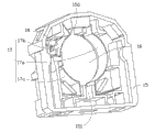
图6为本发明第三实施方式中的灯座截面图。 Fig. 6 is a sectional view of a lamp holder in a third embodiment of the present invention.
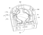
图7为本发明第四实施方式中的灯座截面图。 Fig. 7 is a sectional view of a lamp holder in a fourth embodiment of the present invention.
主要元件符号说明 Description of main component symbols
如下具体实施方式将结合上述附图进一步说明本发明。 The following specific embodiments will further illustrate the present invention in conjunction with the above-mentioned drawings.
具体实施方式 Detailed ways
下面将结合附图,对本发明作进一步的详细说明。 The present invention will be further described in detail below in conjunction with the accompanying drawings.
请同时参阅图1及图2,一种照明装置1,其包括灯管支架10及安装于该灯管支架10上的灯管20,其中,该灯管支架10能够与传统的日光灯管以及LED灯管相适配。该灯管支架10包括一基板11及与该基板11连接的灯座12,该灯座12用于连接日光灯管以及LED灯管。其中,该灯座12包括底盖13、固定件14及本体15,该本体15设置有一通孔16,该固定件14可旋转地收容于底盖13及本体15形成的空间内,固定件14的末端从该通孔16露出。该固定件14上设置有与该通孔16相连通的第一凹槽140,用于收容灯管的金属灯脚。该本体15的上表面边缘处沿通孔16的直径方向设有第二凹槽150。当旋转固定件14使得该第一凹槽140被旋转至与该第二凹槽150相对时,第一凹槽140与第二凹槽150相连通。
Please refer to FIG. 1 and FIG. 2 at the same time. A lighting device 1 includes a
请参阅图3,为第一实施方式中该灯座12的截面视图。在该本体15内部,环绕通孔16设置有至少三个圆弧状的导电弹性件17。在该本体15的内部,与第二凹槽150相对处还形成第三凹槽151,且通孔16的侧壁上在第二凹槽150及第三凹槽151之间形成有至少一个绝缘壁152,该第二凹槽150、第三凹槽151及该至少一个绝缘壁152将该至少三个导电弹性件17彼此绝缘隔开。该灯管支架12还包括LED灯管驱动电路基板及日光灯管驱动电路基板(图未示),设置于该基板11内部,每个导电弹性件17的一端均通过一导线与对应的电路基板电性连接。
Please refer to FIG. 3 , which is a cross-sectional view of the
该灯座12还包括一按压开关18,设置于该至少三个导电弹性件17与本体15边缘形成空间内,并于其中一个连接于LED灯管驱动电路基板的导电弹性件17对应。请同时参阅图4,提供一实施方式的灯管驱动电路示意图50,在该灯管驱动电路50中,该开关18与镇流器52共同连接于一电源50的正极,该开关18的另一端连接至该镇流器52的非电源端,使得当该开关18闭合时,该镇流器52被短路,电源50的电流不流经镇流器52。
The
使用时,转动固定件14至第一凹槽140与第二凹槽150连通的位置处,使灯管20的金属金属灯脚(图未示)穿过由第一凹槽140与第二凹槽150连通形成的凹槽。此后,旋转灯管20,带动固定件14在通孔16中旋转,直至灯管20转动至预定位置(由设置在灯座12上的标识指示),使得旋转该固定件14位于第一位置时,收容于其内的金属灯脚通过该至少三个导电弹性件17中的两个接触,挤压导电弹性件17向远离金属灯脚的方向变形,使得开关18被闭合,LED灯管驱动电路中的镇流器52被短路,电源51的电流不会流经镇流器52。从而在通电后,灯管20受到LED灯管驱动电路基板驱动,即可正常工作。当移出LED灯管的金属灯脚后,对应的导电弹性件17复位使得开关18打开。当该固定件14位于第二位置时,收容于其内的金属灯脚通过至少三个导电弹性件17中的另两个接触,与连接与LED灯管驱动电路的导电弹性件17相对的开关18保持打开的状态,使得电源电流流经镇流器52。从而在通电后,该灯管受到传统日光灯管驱动电路基板驱动,即可正常工作。此时,该灯管金属灯脚收容于第一凹槽140中且第一凹槽140与第二凹槽150错位,从而使得该灯管20的金属金属灯脚不会从灯座12中滑出。如此,对于不同类型的灯管20,只需将其旋转至指示出的预定位置即可使其受到相应的电路基板驱动,从而实现能够使用同一个灯管支架适配不同类型的灯管。
When in use, turn the
在本实施方式中,该至少三个导电弹性件17均为弹片。该至少三个导电弹性件17的数量为3,依次为弹片17a、17b和17c。其中,弹片17a的长度大约为0.5A(A为通孔16的圆周长度),弹片17b及17c的长度大约均为0.25A。该至少一个绝缘壁152的数量为1,这样,弹片17a、17b和17c可被第二凹槽150、第三凹槽151及该绝缘壁152两两隔开。预先设定弹片17a和17b的一端分别连接至LED灯管驱动电路的基板上,弹片17a的另一端与弹片17c的一端分别连接至普通日光灯管驱动电路的基板,该开关18与弹片17b相对设置。即,该第一位置为金属灯脚与弹片17a和17b对应接触时固定件14所处位置,该第二位置为金属灯脚与弹片17a和17c对应接触时固定件14所处位置。
In this embodiment, the at least three conductive
在其他实施方式,还可以预先设定弹片17a和17b的一端分别连接至普通日光灯管驱动电路的基板上,17a和17c的一端分别连接至LED灯管驱动电路的基板上。
In other embodiments, it can also be preset that one ends of the
由于本发明中照明装置1中同时设置LED灯管驱动电路基板与日光灯管驱动电路基板以形成灯管驱动电路50,且共用同一电源51,而镇流器52则需连接至该电源51,因此,连入该灯管驱动电路50中的LED灯管会受到镇流器52的影响,使得LED灯管可能无法正常工作,或导致LED灯管的工作不稳定。因此,通过在灯座12中设置一按压开关18,控制灯管驱动电路50中的镇流器52被短路,使得电源51的电流不流经该镇流器52,从而避免该镇流器52对LED灯管的影响。
In the lighting device 1 of the present invention, the LED lamp tube driving circuit substrate and the fluorescent tube driving circuit substrate are provided at the same time to form the lamp tube driving circuit 50, and share the same power supply 51, and the ballast 52 needs to be connected to the power supply 51, therefore , the LED lamp connected to the lamp driving circuit 50 will be affected by the ballast 52, so that the LED lamp may not work normally, or cause the LED lamp to work unstable. Therefore, by setting a
请参阅图5,为第二实施方式中的灯座12截面图。在本实施方式中,该弹片的数量为4个,依次为弹片27a、27b、27c和27d,其长度大约均为0.25A。该至少一个绝缘壁152的数量为2,这样,弹片27a、27b、27c和27d可被第二凹槽150、第三凹槽151及该两个绝缘壁152两两隔开。预先设定弹片27a和27b的一端分别连接至LED灯管驱动电路的基板上,27c和27d的一端分别连接至普通日光灯管驱动电路的基板上。该第一位置为金属灯脚与弹片27a和27b对应接触时固定件14所处位置,该第二位置为金属灯脚与弹片27c和27d对应接触时固定件14所处位置。在本实施方式中,该开关18与弹片27b相对设置。在其他实施方式,还可以根据需要调整并设定弹片27a、27b、27c和27d所对应连接的灯管驱动电路。
Please refer to FIG. 5 , which is a cross-sectional view of the
请参阅图6,为第三实施方式中的灯座12截面图。在本实施方式中,该弹片的数量为3个,依次为弹片37a、37b和37c,其长度大约均为0.25A,该至少一个绝缘壁152的数量为2。预先设定弹片37a和37b的一端分别连接至普通日光灯管驱动电路的基板上,37c的一端连接至LED灯管驱动电路的基板上。由于不同输入类型的LED灯管,其金属灯脚的导电状态是不同的,当该灯座12中只预先设置1个弹片37c与LED灯管驱动电路基板连接时,可用于接入一端只设有一个导电的金属灯脚的LED灯管,或一端设置两个相互连接的导电金属灯脚的LED灯管。该第一位置为金属灯脚与弹片37c对应接触时固定件14所处位置,该第二位置为金属灯脚与弹片37a和37b对应接触时固定件14所处位置。在本实施方式中,该开关18与弹片37c相对设置。
Please refer to FIG. 6 , which is a cross-sectional view of the
请参阅图7,为第四实施方式中的灯座12截面图。在本实施方式中,该弹片的数量为3个,依次为弹片47a、47b和47c,其长度大约均为0.25A,并设置一长度大约为0.25A的绝缘端47d,该至少一个绝缘壁152的数量为2。其中,该绝缘端47d具有弹性,用于支撑并固定灯管金属灯脚。预先设定弹片47a和47b的一端分别连接至普通日光灯管驱动电路的基板上,弹片47c的一端连接至LED灯管驱动电路的基板上。该第一位置为金属灯脚与弹片47c对应接触时固定件14所处位置,该第二位置为金属灯脚与弹片47a和47b对应接触时固定件14所处位置。在本实施方式中,该开关18与弹片47c相对设置。
Please refer to FIG. 7 , which is a cross-sectional view of the
使用上述可更换LED灯管与普通日光灯管的照明装置1,在灯座12的内部设置至少三个导电弹性件17,并设定每个弹性与设置于灯管支架1中的LED灯管电路基板及普通日光灯管电路基板对应连接。同时,与LED灯管驱动电路基板连接的导电弹性件相对设置一按压开关。通过旋转固定件14,使得插入灯座12的金属灯脚与连接其对应电路基板的导电弹性件相接触,同时,通过导电弹性件的变形使得开关被导通或打开以控制镇流器是否被短路。通电后,灯管20受到对应的灯管驱动电路基板驱动,正常工作,实现与LED灯管和普通日光灯管适配的功能,方便用户使用。
Using the above-mentioned lighting device 1 that can replace LED lamp tubes and ordinary fluorescent tubes, at least three conductive
可以理解的是,对于本领域的普通技术人员来说,可以根据本发明的技术构思做出其它各种相应的改变与变形,而所有这些改变与变形都应属于本发明权利要求的保护范围。 It can be understood that those skilled in the art can make various other corresponding changes and modifications according to the technical concept of the present invention, and all these changes and modifications should belong to the protection scope of the claims of the present invention.
Claims (15)
Priority Applications (3)
| Application Number | Priority Date | Filing Date | Title |
|---|---|---|---|
| CN2011101784686A CN102252198B (en) | 2011-06-29 | 2011-06-29 | LED illumination device |
| TW100124518A TWI426201B (en) | 2011-06-29 | 2011-07-12 | Led illumination device |
| US13/301,805 US8382502B2 (en) | 2011-06-29 | 2011-11-22 | Illumination device with a connector having a retainer with a rotary member and a starter and a swich and elastic pieces |
Applications Claiming Priority (1)
| Application Number | Priority Date | Filing Date | Title |
|---|---|---|---|
| CN2011101784686A CN102252198B (en) | 2011-06-29 | 2011-06-29 | LED illumination device |
Publications (2)
| Publication Number | Publication Date |
|---|---|
| CN102252198A CN102252198A (en) | 2011-11-23 |
| CN102252198B true CN102252198B (en) | 2013-02-13 |
Family
ID=44979658
Family Applications (1)
| Application Number | Title | Priority Date | Filing Date |
|---|---|---|---|
| CN2011101784686A Expired - Fee Related CN102252198B (en) | 2011-06-29 | 2011-06-29 | LED illumination device |
Country Status (3)
| Country | Link |
|---|---|
| US (1) | US8382502B2 (en) |
| CN (1) | CN102252198B (en) |
| TW (1) | TWI426201B (en) |
Families Citing this family (21)
| Publication number | Priority date | Publication date | Assignee | Title |
|---|---|---|---|---|
| US8118447B2 (en) | 2007-12-20 | 2012-02-21 | Altair Engineering, Inc. | LED lighting apparatus with swivel connection |
| US8360599B2 (en) | 2008-05-23 | 2013-01-29 | Ilumisys, Inc. | Electric shock resistant L.E.D. based light |
| US8653984B2 (en) | 2008-10-24 | 2014-02-18 | Ilumisys, Inc. | Integration of LED lighting control with emergency notification systems |
| US8324817B2 (en) | 2008-10-24 | 2012-12-04 | Ilumisys, Inc. | Light and light sensor |
| US8901823B2 (en) | 2008-10-24 | 2014-12-02 | Ilumisys, Inc. | Light and light sensor |
| US7938562B2 (en) | 2008-10-24 | 2011-05-10 | Altair Engineering, Inc. | Lighting including integral communication apparatus |
| US8214084B2 (en) | 2008-10-24 | 2012-07-03 | Ilumisys, Inc. | Integration of LED lighting with building controls |
| WO2011119958A1 (en) | 2010-03-26 | 2011-09-29 | Altair Engineering, Inc. | Inside-out led bulb |
| CA2792940A1 (en) | 2010-03-26 | 2011-09-19 | Ilumisys, Inc. | Led light with thermoelectric generator |
| WO2012058556A2 (en) * | 2010-10-29 | 2012-05-03 | Altair Engineering, Inc. | Mechanisms for reducing risk of shock during installation of light tube |
| WO2013131002A1 (en) | 2012-03-02 | 2013-09-06 | Ilumisys, Inc. | Electrical connector header for an led-based light |
| US9163794B2 (en) | 2012-07-06 | 2015-10-20 | Ilumisys, Inc. | Power supply assembly for LED-based light tube |
| US9271367B2 (en) | 2012-07-09 | 2016-02-23 | Ilumisys, Inc. | System and method for controlling operation of an LED-based light |
| US9285084B2 (en) | 2013-03-14 | 2016-03-15 | Ilumisys, Inc. | Diffusers for LED-based lights |
| US9267650B2 (en) | 2013-10-09 | 2016-02-23 | Ilumisys, Inc. | Lens for an LED-based light |
| WO2015112437A1 (en) | 2014-01-22 | 2015-07-30 | Ilumisys, Inc. | Led-based light with addressed leds |
| US9510400B2 (en) | 2014-05-13 | 2016-11-29 | Ilumisys, Inc. | User input systems for an LED-based light |
| US10161568B2 (en) | 2015-06-01 | 2018-12-25 | Ilumisys, Inc. | LED-based light with canted outer walls |
| CN105955533A (en) * | 2016-05-04 | 2016-09-21 | 武汉华星光电技术有限公司 | Outer-hanging touch display device with pressure-sensing touch function |
| US10051700B1 (en) * | 2016-08-27 | 2018-08-14 | Leo Kwok | Method and apparatus for retrofitting fluorescent tubes to light emitting diodes |
| CN117968027B (en) * | 2024-02-19 | 2024-11-05 | 江苏星康光电科技有限公司 | LED lamp convenient to disassemble |
Citations (5)
| Publication number | Priority date | Publication date | Assignee | Title |
|---|---|---|---|---|
| CN201368365Y (en) * | 2009-02-27 | 2009-12-23 | 深圳磊明科技有限公司 | Variable foot type LED fluorescent light |
| CN201651839U (en) * | 2010-01-04 | 2010-11-24 | 杭州威利广光电科技股份有限公司 | Modified structure of fluorescent lamp |
| DE202010013037U1 (en) * | 2010-12-01 | 2011-02-24 | Harvatek Corp. | Dismountable luminous tube for lighting purposes |
| CN201779482U (en) * | 2010-07-06 | 2011-03-30 | 楼鹏飞 | Light emitting diode (LED) fluorescent lamp fitting with improved structure |
| CN102003644A (en) * | 2010-09-21 | 2011-04-06 | 东莞京洲灯饰有限公司 | LED lighting device |
Family Cites Families (14)
| Publication number | Priority date | Publication date | Assignee | Title |
|---|---|---|---|---|
| CN2309645Y (en) * | 1997-08-01 | 1999-03-03 | 伍本国 | Universal electronic holder for new and old tubular lamp |
| US6113408A (en) * | 1998-10-21 | 2000-09-05 | Lyall Assemblies, Inc. | Non-arcing fluorescent lamp holder |
| US6193534B1 (en) * | 1998-10-21 | 2001-02-27 | Lyall Assemblies, Inc. | Non-arcing fluorescent lamp holder |
| US7052171B1 (en) * | 2004-12-15 | 2006-05-30 | Emteq, Inc. | Lighting assembly with swivel end connectors |
| JP4527525B2 (en) * | 2004-12-28 | 2010-08-18 | 三菱電機株式会社 | Lamp socket and lighting fixture |
| US7556396B2 (en) * | 2007-11-08 | 2009-07-07 | Ledtech Electronics Corp. | Lamp assembly |
| US7927154B2 (en) * | 2008-05-12 | 2011-04-19 | GE Lighting Solutions, LLC | Bi-pin connector and a lamp employing the same |
| US8143811B2 (en) * | 2008-06-25 | 2012-03-27 | Lumetric, Inc. | Lighting control system and method |
| US8297788B2 (en) * | 2008-12-08 | 2012-10-30 | Avx Corporation | Card edge LED strip connector and LED assembly |
| US20100148673A1 (en) * | 2008-12-12 | 2010-06-17 | Glenn Stewart | LED Replacement Light For Fluorescent Lighting Fixtures |
| CN201330950Y (en) * | 2008-12-31 | 2009-10-21 | 广州市鸿利光电子有限公司 | LED lamp tube |
| JP5171661B2 (en) * | 2009-01-20 | 2013-03-27 | シャープ株式会社 | LED lighting fixtures |
| CN101839416B (en) * | 2010-02-02 | 2011-12-14 | 鸿富锦精密工业(深圳)有限公司 | Lighting system and its universal lamp holder |
| TWM402385U (en) * | 2010-08-31 | 2011-04-21 | Jade Yang Co Ltd | Lamp holder structure of LED lamp tube |
-
2011
- 2011-06-29 CN CN2011101784686A patent/CN102252198B/en not_active Expired - Fee Related
- 2011-07-12 TW TW100124518A patent/TWI426201B/en not_active IP Right Cessation
- 2011-11-22 US US13/301,805 patent/US8382502B2/en not_active Expired - Fee Related
Patent Citations (5)
| Publication number | Priority date | Publication date | Assignee | Title |
|---|---|---|---|---|
| CN201368365Y (en) * | 2009-02-27 | 2009-12-23 | 深圳磊明科技有限公司 | Variable foot type LED fluorescent light |
| CN201651839U (en) * | 2010-01-04 | 2010-11-24 | 杭州威利广光电科技股份有限公司 | Modified structure of fluorescent lamp |
| CN201779482U (en) * | 2010-07-06 | 2011-03-30 | 楼鹏飞 | Light emitting diode (LED) fluorescent lamp fitting with improved structure |
| CN102003644A (en) * | 2010-09-21 | 2011-04-06 | 东莞京洲灯饰有限公司 | LED lighting device |
| DE202010013037U1 (en) * | 2010-12-01 | 2011-02-24 | Harvatek Corp. | Dismountable luminous tube for lighting purposes |
Also Published As
| Publication number | Publication date |
|---|---|
| TW201300686A (en) | 2013-01-01 |
| TWI426201B (en) | 2014-02-11 |
| US8382502B2 (en) | 2013-02-26 |
| CN102252198A (en) | 2011-11-23 |
| US20130003365A1 (en) | 2013-01-03 |
Similar Documents
| Publication | Publication Date | Title |
|---|---|---|
| CN102252198B (en) | LED illumination device | |
| TWI425164B (en) | Led illumination device | |
| CN102252288B (en) | Lamp tube bracket | |
| CN103459921B (en) | End Caps for Tube Light Sources | |
| TW201017042A (en) | Led lamp | |
| CN102128372A (en) | LED (light-emitting diode) daylight lamp | |
| CN104584332B (en) | Method and device for grounding electrical installations through lampholders | |
| CN102207257B (en) | LED (light-emitting diode) lighting device | |
| CN104180321B (en) | Self-powered rotary type holder structure and lamp combination | |
| CN102313172B (en) | LED lighting | |
| ES2870453T3 (en) | Lighting device | |
| CN102252197B (en) | Light-emitting diode (LED) lighting device | |
| CN102207258B (en) | LED (light-emitting diode) lighting device | |
| TW201734361A (en) | Lamp and lamp socket having multiple connectors | |
| CN201093424Y (en) | Lamp holder for installing several energy-saving lamps | |
| CN219576120U (en) | Rail-mounted wireless switching system | |
| CN206369092U (en) | Insert isolated end cap and LED | |
| US8764477B2 (en) | Plug wire type lampholder | |
| TWI452941B (en) | Tube switching apparatus | |
| JP2014099329A (en) | Straight tube type led lamp and lighting device | |
| CN2935707Y (en) | Sodium light bulb with starter mechanism | |
| JP5127044B2 (en) | lighting equipment | |
| JP4951539B2 (en) | lighting equipment | |
| CN102954450A (en) | Lamp tube switching device | |
| CN101359800A (en) | Lamp holder for installing several energy-saving lamps |
Legal Events
| Date | Code | Title | Description |
|---|---|---|---|
| C06 | Publication | ||
| PB01 | Publication | ||
| C10 | Entry into substantive examination | ||
| SE01 | Entry into force of request for substantive examination | ||
| C14 | Grant of patent or utility model | ||
| GR01 | Patent grant | ||
| CF01 | Termination of patent right due to non-payment of annual fee |
Granted publication date: 20130213 Termination date: 20160629 |
|
| CF01 | Termination of patent right due to non-payment of annual fee |