CN102236405A - Information equipment capable of reducing standby power and power control method - Google Patents
Information equipment capable of reducing standby power and power control method Download PDFInfo
- Publication number
- CN102236405A CN102236405A CN2011101054749A CN201110105474A CN102236405A CN 102236405 A CN102236405 A CN 102236405A CN 2011101054749 A CN2011101054749 A CN 2011101054749A CN 201110105474 A CN201110105474 A CN 201110105474A CN 102236405 A CN102236405 A CN 102236405A
- Authority
- CN
- China
- Prior art keywords
- power
- internal unit
- information equipment
- unit
- electric power
- Prior art date
- Legal status (The legal status is an assumption and is not a legal conclusion. Google has not performed a legal analysis and makes no representation as to the accuracy of the status listed.)
- Pending
Links
Images


Classifications
-
- G—PHYSICS
- G06—COMPUTING OR CALCULATING; COUNTING
- G06F—ELECTRIC DIGITAL DATA PROCESSING
- G06F1/00—Details not covered by groups G06F3/00 - G06F13/00 and G06F21/00
- G06F1/26—Power supply means, e.g. regulation thereof
- G06F1/32—Means for saving power
- G06F1/3203—Power management, i.e. event-based initiation of a power-saving mode
- G06F1/3234—Power saving characterised by the action undertaken
- G06F1/3287—Power saving characterised by the action undertaken by switching off individual functional units in the computer system
-
- G—PHYSICS
- G06—COMPUTING OR CALCULATING; COUNTING
- G06F—ELECTRIC DIGITAL DATA PROCESSING
- G06F1/00—Details not covered by groups G06F3/00 - G06F13/00 and G06F21/00
- G06F1/26—Power supply means, e.g. regulation thereof
- G06F1/266—Arrangements to supply power to external peripherals either directly from the computer or under computer control, e.g. supply of power through the communication port, computer controlled power-strips
-
- G—PHYSICS
- G06—COMPUTING OR CALCULATING; COUNTING
- G06F—ELECTRIC DIGITAL DATA PROCESSING
- G06F1/00—Details not covered by groups G06F3/00 - G06F13/00 and G06F21/00
- G06F1/26—Power supply means, e.g. regulation thereof
- G06F1/32—Means for saving power
- G06F1/3203—Power management, i.e. event-based initiation of a power-saving mode
- G06F1/3206—Monitoring of events, devices or parameters that trigger a change in power modality
- G06F1/3212—Monitoring battery levels, e.g. power saving mode being initiated when battery voltage goes below a certain level
-
- G—PHYSICS
- G06—COMPUTING OR CALCULATING; COUNTING
- G06F—ELECTRIC DIGITAL DATA PROCESSING
- G06F1/00—Details not covered by groups G06F3/00 - G06F13/00 and G06F21/00
- G06F1/26—Power supply means, e.g. regulation thereof
- G06F1/32—Means for saving power
- G06F1/3203—Power management, i.e. event-based initiation of a power-saving mode
- G06F1/3206—Monitoring of events, devices or parameters that trigger a change in power modality
- G06F1/3215—Monitoring of peripheral devices
-
- G—PHYSICS
- G06—COMPUTING OR CALCULATING; COUNTING
- G06F—ELECTRIC DIGITAL DATA PROCESSING
- G06F1/00—Details not covered by groups G06F3/00 - G06F13/00 and G06F21/00
- G06F1/26—Power supply means, e.g. regulation thereof
- G06F1/32—Means for saving power
- G06F1/3203—Power management, i.e. event-based initiation of a power-saving mode
- G06F1/3234—Power saving characterised by the action undertaken
- G06F1/325—Power saving in peripheral device
- G06F1/3278—Power saving in modem or I/O interface
-
- Y—GENERAL TAGGING OF NEW TECHNOLOGICAL DEVELOPMENTS; GENERAL TAGGING OF CROSS-SECTIONAL TECHNOLOGIES SPANNING OVER SEVERAL SECTIONS OF THE IPC; TECHNICAL SUBJECTS COVERED BY FORMER USPC CROSS-REFERENCE ART COLLECTIONS [XRACs] AND DIGESTS
- Y02—TECHNOLOGIES OR APPLICATIONS FOR MITIGATION OR ADAPTATION AGAINST CLIMATE CHANGE
- Y02D—CLIMATE CHANGE MITIGATION TECHNOLOGIES IN INFORMATION AND COMMUNICATION TECHNOLOGIES [ICT], I.E. INFORMATION AND COMMUNICATION TECHNOLOGIES AIMING AT THE REDUCTION OF THEIR OWN ENERGY USE
- Y02D10/00—Energy efficient computing, e.g. low power processors, power management or thermal management
-
- Y—GENERAL TAGGING OF NEW TECHNOLOGICAL DEVELOPMENTS; GENERAL TAGGING OF CROSS-SECTIONAL TECHNOLOGIES SPANNING OVER SEVERAL SECTIONS OF THE IPC; TECHNICAL SUBJECTS COVERED BY FORMER USPC CROSS-REFERENCE ART COLLECTIONS [XRACs] AND DIGESTS
- Y02—TECHNOLOGIES OR APPLICATIONS FOR MITIGATION OR ADAPTATION AGAINST CLIMATE CHANGE
- Y02D—CLIMATE CHANGE MITIGATION TECHNOLOGIES IN INFORMATION AND COMMUNICATION TECHNOLOGIES [ICT], I.E. INFORMATION AND COMMUNICATION TECHNOLOGIES AIMING AT THE REDUCTION OF THEIR OWN ENERGY USE
- Y02D30/00—Reducing energy consumption in communication networks
- Y02D30/50—Reducing energy consumption in communication networks in wire-line communication networks, e.g. low power modes or reduced link rate
Landscapes
- Engineering & Computer Science (AREA)
- Theoretical Computer Science (AREA)
- General Engineering & Computer Science (AREA)
- Physics & Mathematics (AREA)
- General Physics & Mathematics (AREA)
- Computer Hardware Design (AREA)
- Computing Systems (AREA)
- Power Sources (AREA)
- Charge And Discharge Circuits For Batteries Or The Like (AREA)
Abstract
本发明提供一种能够降低待机电力的信息设备以及电力的控制方法。在笔记本PC中装配了以太网控制器。笔记本PC通过计时器的设定使向以太网控制器供给电力的DC/DC变换器间歇动作。在变换器开启的Twake的时间的期间,判断以太网控制器是否通过电缆与网络连接。在判断为连接时,直到断开连接为止维持DC/DC变换器的动作。在判断没有连接时,使DC/DC变换器停止Tsleep的期间,在经过了计时器的设定时间时再次使DC/DC变换器动作。DC/DC变换器仅在实际与网络连接时,向以太网控制器供给电力。
The present invention provides an information device capable of reducing standby power and a power control method. An Ethernet controller is installed in the notebook PC. The notebook PC intermittently operates the DC/DC converter that supplies power to the Ethernet controller by setting a timer. During the Twake time when the converter is turned on, it is determined whether the Ethernet controller is connected to the network through a cable. When it is determined to be connected, the operation of the DC/DC converter is maintained until the connection is disconnected. When it is judged that there is no connection, the DC/DC converter is stopped for Tsleep, and the DC/DC converter is activated again when the time set by the timer has elapsed. The DC/DC converter supplies power to the Ethernet controller only when it is actually connected to the network.
Description
技术领域 technical field
本发明涉及降低信息设备的待机电力,更详细地说是涉及在不降低连接了外部设备时提供的功能的状况下降低待机电力的技术。The present invention relates to reduction of standby power of information equipment, and more specifically relates to a technology for reducing standby power without reducing functions provided when external equipment is connected.
背景技术 Background technique
近年来,在强化对电子产品的环境限制的同时,在EU各国制定并采用了EuP指令(Directive on Eco-Design of Energy-using Products)。在Eup指令中,对于信息技术设备(information technology equipment),到2013年分别要求在与商用电源连接状态下的待机模式以及离线模式下的消耗电力不超过0.5W。笔记本型个人计算机(以下称为笔记本PC)装配了电池组,在外出目的地通过电池组供给的电力进行工作,在办公室经由AC/DC适配器通过商用电源供给的电力进行工作。In recent years, while strengthening environmental restrictions on electronic products, EU countries have formulated and adopted the EuP Directive (Directive on Eco-Design of Energy-using Products). In the Eup Directive, for information technology equipment (information technology equipment), by 2013, the power consumption in standby mode and offline mode when connected to a commercial power supply is required to be no more than 0.5W. A notebook personal computer (hereinafter referred to as a notebook PC) is equipped with a battery pack, and operates with power supplied from the battery pack at a destination, and operates with power supplied from a commercial power supply via an AC/DC adapter in the office.
在安装有电池组的笔记本PC上连接了AC/DC适配器时,AC/DC适配器同时供给电池组的充电电力和系统的工作电力。在笔记本PC中,即使是关机状态也需要向一部分设备供给电力。在笔记本PC中,在关机状态下,在连接了AC/DC适配器的状态(以后称为AC供给)和未连接AC/DC适配器的状态(以后称为DC供给)下提供不同的服务或功能。When an AC/DC adapter is connected to a notebook PC with a battery pack installed, the AC/DC adapter supplies charging power for the battery pack and operating power for the system at the same time. In notebook PCs, power needs to be supplied to some devices even in the off state. In a notebook PC, different services or functions are provided in a state in which an AC/DC adapter is connected (hereinafter referred to as AC supply) and a state in which the AC/DC adapter is not connected (hereinafter referred to as DC supply) in an off state.
在笔记本PC通过DC供给进入到关机状态时,为了能够防止电池的消耗仅对重启动需要的电路供给电力,所以消耗电力小。但是,在通过AC供给进入到关机状态时,为了提供各种服务消耗电力增大。首先,当在关机状态下也需要在对电池组充电时,使充电器工作来进行充电,所以监视电池的充电状态进行充电的电路消耗电力。When the notebook PC is turned off by DC supply, power is only supplied to circuits required for restart in order to prevent battery consumption, so the power consumption is small. However, when the power is turned off by AC supply, power consumption increases for providing various services. First, when it is necessary to charge the battery pack even in the off state, the charger is operated to charge the battery, so the circuit that monitors the state of charge of the battery and charges the battery consumes power.
此外,在为了远程启动而使远程唤醒(WOL)功能有效时,收到启动数据包(packet)使笔记本PC启动的电路消耗电力。并且,当支持在关机状态时连接的USB设备的充电时,USB设备的充电电路消耗电力。并且,为了用户使用方便,表示AC/DC适配器的连接状态、电池组的充电状态、以及电力状态等的电路、或用于进行与电力状态对应的启动的电路等也消耗电力。由此,在笔记本PC中,通过AC供给进入关机状态时,具有消耗比较大的待机电力的倾向。In addition, when the remote wake-up (WOL) function is enabled for remote start-up, a circuit that activates the notebook PC upon receipt of a start-up packet consumes power. Also, when supporting the charging of the USB device connected in the power-off state, the charging circuit of the USB device consumes power. Also, for user convenience, circuits indicating the connection state of the AC/DC adapter, the charging state of the battery pack, and the power state, or circuits for performing startup corresponding to the power state also consume power. Therefore, when the notebook PC is turned off by AC supply, relatively large standby power tends to be consumed.
专利文献1公开了削减具备电池的计算机装置存在AC电源并且关闭状态时的待机电力的技术。通过该文献的充电方法,在存在AC电源并已关机时,在暂时关闭实现充电功能的M电源系统之后经过了计时器测量的预定的时间后,开启M电源系统,确认电池的充电状态。然后,在判断为需要充电时在充电后再次关闭M电源系统。此外,在该文献中记载了在存在AC电源并且已关机时,通过软件的设定关闭与M电源连接的不需要的电池以及远程唤醒功能。
专利文献2公开了在与服务器连接的LAN电缆连接在以太网(注册商标)控制器上时,CPU自动地识别服务器,省去用户识别服务器的技术。在该文献中,当以太网(注册商标)控制器检测到在LAN插口上安装了LAN电缆时,对CPU施加中断来进行通知。
专利文献3公开了一种打印机,是具备包含USB的多个I/F的打印机,能够通过检测USB电缆的连接,自动变更I/F。在该文献中,在通过USB电缆将打印机连接在主计算机上时,打印机的USB连接检测部检测Vbus的电位的变化,检测连接了USB电缆。在专利文献4中记载了在检测到在与PCIe-PCIe桥连接的多个PCIe插槽中都没有安装卡时,控制PCI-ePCI-e桥专用的DC/DC转换器来停止向PCI-ePCI-e桥供给电源。
【专利文献1】日本特开2004-192350号公报[Patent Document 1] Japanese Patent Laid-Open No. 2004-192350
【专利文献2】日本特开2009-278288号公报[Patent Document 2] Japanese Unexamined Patent Publication No. 2009-278288
【专利文献3】日本特开2010-33519号公报[Patent Document 3] Japanese Patent Laid-Open No. 2010-33519
【专利文献4】日本特开2009-199297号公报[Patent Document 4] Japanese Patent Laid-Open No. 2009-199297
发明内容 Contents of the invention
在专利文献1的方法中,在关机后经过了预定时间时,使M电源系统工作来对监视电池的充电状态的电路供给电力,所以能够降低停止M电源系统的期间的待机电力。但是,在M电源系统是用于其它服务的电源时,有时也无法停止M电源系统。特别是在美国环境保护局推进的电气设备的节电项目(能源之星)中,规定在企业中使用的计算机原则上开启WOL功能,并且使对于用户始终开启WOL功能成为企业的义务,所以此时,在专利文献1的方法中无法停止M电源系统。In the method of
并且,在需要支持与关机状态的笔记本PC连接的USB设备的充电时,只要不设置与M电源系统不同的新的电源电路,就无法关闭M电源系统。因此,在专利文献1的方法中,无法降低AC供给下的待机电力到充分满足Eup指令的程度,或者无法进行USB设备的充电。因为在关机状态下不执行操作系统(OS)以及设备驱动器,所以难以判断M电源系统工作的必要性,需要花费特别的工夫。In addition, when it is necessary to support charging of a USB device connected to a notebook PC in a power-off state, the M power supply system cannot be turned off unless a new power supply circuit different from the M power supply system is provided. Therefore, with the method of
因此,本发明的目的在于提供一种信息设备,其能够在不降低关机状态时的服务的状况下降低待机电力。并且,本发明的目的在于提供一种信息设备,即使在关机状态时将WOL设定为开启,也能够降低待机电力。并且,本发明的目的在于提供信息设备,能够在关机状态时在能够对USB设备充电的同时降低待机电力。并且,本发明的目的在于提供这样的信息设备中的电力的控制方法以及电力控制系统。Therefore, an object of the present invention is to provide an information device capable of reducing standby power without reducing service in a power-off state. Furthermore, an object of the present invention is to provide an information device capable of reducing standby power even when WOL is turned on in a power-off state. Furthermore, an object of the present invention is to provide an information device capable of reducing standby power while being able to charge a USB device in a power-off state. Furthermore, an object of the present invention is to provide a power control method and a power control system in such information equipment.
本发明提供能够降低在关机状态时从商用电源取得的电力的信息设备。能够通过连接器等在信息设备上连接外部设备。信息设备在连接了外部设备时、在关机状态时,能够通过内部设备的动作提供预定的功能或服务。因此,在关机状态下,不完全停止信息设备的电力,通过内部设备的动作消耗待机电力。关机状态在ACPI的电力状态中可以设为S5状态以及S4状态。在此,存在在信息设备上连接外部设备的情况和不连接的情况,在未连接外部设备时,内部设备不需要提供预定的功能或服务。The present invention provides an information device capable of reducing the power drawn from a commercial power supply in a power-off state. It is possible to connect an external device to an information device through a connector or the like. When an information device is connected to an external device or in a power-off state, it can provide predetermined functions or services through the actions of the internal device. Therefore, in the shutdown state, the power of the information device is not completely stopped, and the standby power is consumed by the operation of the internal device. The shutdown state can be set to the S5 state and the S4 state in the ACPI power state. Here, there are cases where an external device is connected to the information device and cases where it is not connected, and when the external device is not connected, the internal device does not need to provide a predetermined function or service.
控制部可以维持或者停止在关机状态下对内部设备的电力供给。在内部设备接受电力供给时,能够识别外部设备的连接或非连接,控制部在内部设备识别出连接了外部设备时维持对内部设备的电力供给,当识别出未连接外部设备时,停止预定时间对内部设备的电力供给。由此,内部设备在识别出没有连接外部设备时,可以将内部设备的待机电力降低预定时间。即使暂时停止对内部设备的电力供给,在经过预定时间后对内部设备供给电力。The control unit can maintain or stop power supply to internal devices in the power-off state. When the internal device receives power supply, it can recognize whether the external device is connected or not. The control unit maintains the power supply to the internal device when the internal device recognizes that the external device is connected, and stops for a predetermined time when it recognizes that the external device is not connected. Power supply to internal equipment. Thus, when the internal device recognizes that the external device is not connected, the standby power of the internal device can be reduced for a predetermined time. Even if the power supply to the internal device is temporarily stopped, power is supplied to the internal device after a lapse of a predetermined time.
然后,在内部设备识别出连接了外部设备时,因为内部设备动作所以不会导致在关机状态的期间要求的服务或功能的降低。可以从DC/DC转换器这样的电源对内部设备供给电力。控制部能够通过控制电源的动作,来控制针对内部设备的电力。电源能够对与在关机状态下提供的服务相关联的远程唤醒电路或USB设备的充电电路供给电力。Then, when the internal device recognizes that the external device is connected, since the internal device operates, services or functions required during the shutdown state will not be reduced. Power can be supplied to internal devices from a power source such as a DC/DC converter. The control unit can control the power for internal devices by controlling the operation of the power supply. The power supply is capable of powering remote wake-up circuitry associated with services provided in the powered-off state or charging circuitry for USB devices.
内部设备能够在维持电力供给的期间识别外部设备从连接变化为非连接。由此,即使在暂时维持针对内部设备的电力供给后取下外部设备时,控制部也能够停止对内部设备的电力供给,能够有效地实现待机电力的降低。可以把内部设备设为网络控制器,把外部设备设为网络设备。The internal device can recognize that the external device has changed from being connected to not being connected while the power supply is maintained. As a result, even when the external device is removed after temporarily maintaining the power supply to the internal device, the control unit can stop the power supply to the internal device, thereby effectively reducing standby power. The internal device can be set as a network controller, and the external device can be set as a network device.
在内部设定是网络控制器时,能够根据在确立连接之前进行的自动协商,来识别网络设备的连接或非连接。在网络控制器具备PCI Express的接口的情况下,控制部能够根据网络控制器输出的CLKREQ#信号,识别外部设备的连接或非连接。可以把内部设备设为USB电力控制器,把外部设备设为安装电池的USB设备。此时,USB电力控制器可以根据对USB设备供给的充电电流的大小,识别USB设备的连接或非连接。结果,即使连接了USB设备,在实际不需要充电时,也可以停止USB电力控制器来降低待机电力。When the internal setting is a network controller, the connection or non-connection of the network device can be recognized based on the auto-negotiation performed before the connection is established. When the network controller has a PCI Express interface, the control unit can identify whether the external device is connected or not according to the CLKREQ# signal output by the network controller. The internal device can be set as a USB power controller, and the external device can be set as a USB device with a battery installed. At this time, the USB power controller can recognize whether the USB device is connected or not according to the magnitude of the charging current supplied to the USB device. As a result, even if a USB device is connected, when charging is actually not required, the USB power controller can be stopped to reduce the standby power.
根据本发明,可以提供在不降低关机状态时的服务的状况下降低待机电力的信息设备。并且,根据本发明,可以提供即使在关机状态时将WOL设定为开启,也能够降低待机电力的信息设备。并且,根据本发明,可以提供在关机状态时在能够对USB设备充电的同时还能够降低待机电力的信息设备。并且,根据本发明,可以提供这样的信息设备中的电力的控制方法以及电力控制系统。According to the present invention, it is possible to provide an information device that reduces standby power without reducing service in a power-off state. Furthermore, according to the present invention, it is possible to provide an information device capable of reducing standby power even when WOL is turned on in a power-off state. Furthermore, according to the present invention, it is possible to provide an information device capable of charging a USB device while reducing standby power in a power-off state. Furthermore, according to the present invention, it is possible to provide a power control method and a power control system in such an information device.
附图说明 Description of drawings
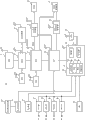
图1是表示本实施方式的笔记本PC100的主要结构的概要的功能框图。FIG. 1 is a functional block diagram showing an outline of main configurations of a notebook PC 100 according to the present embodiment.
图2是用于说明对LAN交换机或USB设备的连接进行检测的电路的图。FIG. 2 is a diagram for explaining a circuit for detecting connection of a LAN switch or a USB device.
图3是表示在笔记本PC上连接了AC/DC适配器时降低待机电力的顺序的流程图。FIG. 3 is a flowchart showing a procedure for reducing standby power when an AC/DC adapter is connected to the notebook PC.
图4表示DC/DC变换器在关机期间进行间歇动作的样态。Fig. 4 shows how the DC/DC converter performs intermittent operation during shutdown.
符号说明Symbol Description
10笔记本PC;17输入/输出控制集线器(hub);19嵌入式控制器;21以太网控制器;25USB电力控制器10 notebook PC; 17 input/output control hub (hub); 19 embedded controller; 21 Ethernet controller; 25USB power controller
具体实施方式 Detailed ways
图1是表示本实施方式的笔记本PC100的主要结构的概要的功能框图。图2是用于说明对LAN交换机63或USB设备67的连接进行检测的电路的图。CPU11与存储器控制集线器(MCH)13连接,在MCH13上连接GPU(GraphicsProcessing Unit)14、主存储器15以及输入/输出控制集线器(ICH)17。ICH17具备USB(Universal Serial Bus)、SATA(Serial AT Attachment)、SPI(SerialPeripheral Interface)总线、PCI(Peripheral Component Interconnect)总线、PCI-Express(PCIe)总线以及LPC(Low Pin Count)总线等接口,能够连接与这些接口对应的设备。FIG. 1 is a functional block diagram showing an outline of main configurations of a notebook PC 100 according to the present embodiment. FIG. 2 is a diagram for explaining a circuit for detecting connection of the LAN switch 63 or the
在图1中,在ICH17的SATA端口上连接了硬盘驱动器(HDD)18,在PCIe端口上连接了以太网控制器21,在USB端口上连接了USB连接器27,在LPC端口上连接了嵌入式控制器(EC)19。ICH17还包含把WOL设定为开启或禁用的寄存器。当用户通过BIOS或OS在寄存器中把WOL设定为开启时,当在关机时以太网控制器21收到魔术数据包时,ICH17通过EC19使笔记本PC10转移到开机状态。In Fig. 1, a hard disk drive (HDD) 18 is connected to the SATA port of the ICH17, an
EC19是由8~16位的CPU、ROM、RAM等构成的微型计算机,并且具备多个通道的A/D输入端子、D/A输出端子、计时器以及数字输入输出端子。EC19相对于CPU11独立地动作,根据电力状态控制对安装在笔记本PC10中的设备供给的电力,或通过散热风扇(未图示)控制系统机箱内部的温度。EC19 is a microcomputer composed of 8 to 16-bit CPU, ROM, RAM, etc., and has multiple channels of A/D input terminals, D/A output terminals, timers, and digital input and output terminals. The
在图2中,以太网(注册商标)控制器21包含PCIe接口部53、存储器部54、MAC(media access control)部55、PHY(physical)部56、脉冲变压器57以及连接检测部59。PCIe接口部53通过发送和接收双向的总共4条信号线构成的线道(lane)连接在ICH17的PCIe端口51上,控制与CPU11之间的数据包传输。存储器部54包含存储数据包的收发用缓冲存储器。MAC部55通过MAC帧的编码、解码、前置码(preamble)的生成以及接收帧的选择等控制数据包,并且支持冲突检测以及WOL等。PHY部56具备收发部,双向变换数字数据和电信号。In FIG. 2 , the Ethernet (registered trademark)
脉冲变压器57使以太网控制器21的内部与外部电气绝缘。RJ45连接器23是用于连接UTP电缆61的8芯的模块式连接器,设置在笔记本PC10的机箱中。在RJ45连接器23上,经由UTP(Unshielded Twisted Pair)电缆61连接了LAN交换机63。LAN交换机63是被称为层2交换机或层3交换机的网络设备。The pulse transformer 57 electrically insulates the inside of the
PHY部56在通过UTP电缆61将被供给了电力的LAN交换机63和RJ45连接器连接的状态下,当对以太网控制器21供给了电力时,开始LAN交换机63和自动协商。或者在对以太网控制器21供给电力的状态下,PHY部56在通过UTP电缆61连接了被供给电力的LAN交换机63时开始自动协商。自动协商是指在以太网控制器21和LAN交换机63之间,根据各自具有的传输速度以及通信方式在链路(连接)确立之前设定适当的接口的功能。When the
在本实施方式中,能够以始终对LAN交换机63供给电力为前提。因此,说明在UTP电缆61与RJ45连接器23连接的状态下在对以太网控制器21供给电力时,或者在对以太网控制器21供给电力的期间通过在RJ45连接器23上连接UTP电缆61,来开始自动协商。In the present embodiment, it can be assumed that power is always supplied to the
当对以太网控制器21提供了电力时,无论是否连接了UTP电缆61,PHY部56都持续送出FLP(Fast Link Pulse)。通过LAN交换机63对此返回FLP来开始自动协商。PHY部56通过接收来自LAN交换机63的响应脉冲自动协商完成,能够识别实际与网络连接。When power is supplied to the
一旦确立了连接后,以太网控制器21定期地送出FLP,即使在不存在收发的数据包时,也持续地确认是否为实际上不存在数据或者是否拔掉了UTP电缆。然后,在拔掉了UTP电缆61时,在此之后再次连接了UTP电缆61的时刻开始自动协商。Once the connection is established, the
在向以太网控制器21供给了电力时,或者在对以太网控制器21供给电力的期间,PHY部56当识别出在进行UTP电缆61的插拔时执行的自动协商成功时,向连接检测部59发送表示在RJ连接器23上连接了LAN交换机23的连接信号。连接信号还可以表示网络一侧能够经由RJ45连接器23与LAN交换机63之间进行通信。另外,PHY部56在与不支持自动协商的LAN交换机之间,能够在发送了FLP之后通过从LAN交换机接收NLP(Normal LinkPulse),确立连接输出连接信号。When power is supplied to the
PHY部56不仅可以将连接信号作为表示连接了UTP电缆61的信号进行输出,还能够作为表示没有连接UTP电缆61的信号进行输出。当在ICH17的寄存器中把WOL设定为开启时,需要即使已关机也向以太网控制器21供给电力持续等待从网络发送来的魔术包(magic packet)。但是,在LAN交换机63实际上没有与RJ45连接器23连接时,以太网控制器21因为不可能取得魔术包,所以即使停止动作WOL功能也不会降低。连接检测部59把从PHY部56取得的连接信号输出给ICH的时钟振荡器58和EC19的数字输入。The
时钟振荡器58向以太网控制器21提供基准时钟(REFCLK)。然后,可以使连接信号成为以太网控制器21向时钟振荡器58要求基准时钟的信号(CLKREQ#信号)。以太网控制器21在停止内部的PLL以省电模式进行动作时,在向通常模式转移时向时钟振荡器58输出CLKREQ#信号。CLKREQ#信号是在要求基准时钟时成为低电平在不要求基准时钟时成为高电平的信号。当基准时钟停止时以太网控制器21的内部的PLL停止。作为在RJ45连接器23上连接了UTP电缆61时输出CLKREQ#信号的以太网控制器,例如有因特尔公司的型号为82577LM的IC芯片。The
在本发明中通过以太网控制器进行的UTP电缆的连接或非连接的检测不限于使用自动协商功能的方法,还可以采用在系统关机的状态下在CPU不执行设备驱动器或OS的环境下检测与网络设备的连接的其他的方法。例如,可以在供给电力时以太网控制器自动输出脉冲,根据连接了网络设备时和未连接网络设备时的脉冲信号的电气不同,检测有无连接。The detection of the connection or non-connection of the UTP cable carried out by the Ethernet controller in the present invention is not limited to the method using the auto-negotiation function, and it is also possible to detect in an environment where the CPU does not execute the device driver or the OS in the state where the system is turned off. Other methods of connection to network devices. For example, the Ethernet controller can automatically output pulses when power is supplied, and detect the presence or absence of connection based on the electrical difference between the pulse signal when the network device is connected and when the network device is not connected.
ICH17的USB端口52通过一组的差分数据线(±DATA)与USB连接器27相连接。USB电力控制器25通过USB_ON线和USBCHG#信号的线与EC19的数字端子连接。电力控制器25通过Vbus线和GND线与USB连接器27连接。在USB连接器27上通过USB电缆65连接了USB设备67。将USB连接器27设置在笔记本PC10的机箱内。The
USB电力控制器25向正在动作的USB设备67供给电力,还具备用于对装配在USB设备67中的电池进行充电的充电功能。EC19能够设定或者参照USBCHG比特88(参照图1),USBCHG比特88表示在笔记本PC10为关机状态时,是否提供对与USB连接器27连接的USB设备67进行充电的功能。The
EC19在设定了USBCHG比特88时,即使在关机状态下也通过USB_ON线使USB控制器25动作,在未设定USBCHG比特88时,仅在开机状态时以及挂起状态时使USB控制器25动作。USB电力控制器25具备USB设备67的充电功能,在充电电流为预定值以上时或者在不满预定值时,可以向EC19的数字端子输出USBCHGRE#信号。USBCHG#信号相当于表示USB设备67与USB连接器27连接或非连接的信号,或者表示在连接时在该时刻实际上是否需要进行充电的信号。When the
因此,EC19即使设定了USBCHG比特88,也可以根据USBCHG#信号识别在为关机状态时在USB连接器27上没有连接USB设备67的状况,或者即使已连接但实际上不需要对USB设备67进行充电的状况,停止USB电力控制器25。在不可能对USB设备67充电时即使EC19停止USB电力控制器25的动作,对于笔记本PC10来说也不会引起关机状态下的针对USB设备67的充电功能的降低。Therefore, even if the
返回图1,在EC19上通过SM总线连接了电池组35,通过SPI总线连接了电源控制电路29。电池组35基于以美国英特尔公司以及美国金霸王公司为主倡导的被称为智能电池系统(SBS:Smart Battery System)的规格,成为没有连接AC/DC适配器33时的笔记本PC10的电源。Returning to FIG. 1 , the
电池组35当在笔记本PC10上连接了AC/DC适配器33时,通过AC/DC适配器33供给的电力通过充电器(未图示)进行充电。AC/DC适配器33的一次侧与商用电源的插座连接,二次侧与笔记本PC10的机箱连接。AC/DC适配器33可以装入笔记本PC10的机箱内。AC/DC适配器33把交流电压变换为直流电压,经由DC/DC变换器37~43对系统设备供给电力,并且能够向充电器供给电力对电池组35充电。在AC/DC适配器33的输出上连接有电压检测器34。电压检测器34在检测到在AC/DC适配器33的输出中产生了预定范围的电压时,输出表示它的电压检测信号ACPWR。The
电源控制电路29由包含模拟电路以及数字电路的ASIC(ApplicationSpecific Integrated Circuit)构成,包含寄存器81、控制电路89、计时器91。在电源控制电路29上连接有电压检测器34、DC/DC变换器37~43、电源按钮45、以及LED31。电源按钮45设置在笔记本PC10的机箱上,在用户对电源进行开/关操作时使用。The power
LED31表示连接了AC/DC适配器33时的电池组35的充电状态。控制电路89从EC19接收指示控制DC/DC变换器37~43的动作,或者控制针对电池组35的充放电电路。寄存器81包含从电压检测器34取得电压检测信号ACPWR时设定的ACPWR比特83、在按下了电源按钮45时设定的PB比特85、在ICH17的寄存器中进行使WOL开启的设定的同时设定的WOL比特87、表示是否开启在笔记本PC10为关机状态时对连接在USB连接器27上的USB设备67进行充电的功能的USBCHG比特88。
在使笔记本PC10转移到开机状态时,为了判断启动事件的种类通过EC19参照PB比特85,在笔记本PC10转移到开机状态后,通过电源控制电路29对PB比特85进行复位。在笔记本PC10开机过程中,根据用户通过OS以及BIOS进行的针对EC19的指示,EC19在寄存器81中设定WOL比特87以及USBCHG比特88。计时器91在关机状态的期间,对用于使DC/DC变换器39间歇动作的时间进行计数。关于间歇动作,之后进行说明。When the
笔记本PC10适合于ACPI的规格,可以迁移到G0状态、G1状态、G2状态、以及G3状态这4个全局系统状态。G0状态相当于电力状态的S0状态,CPU11成为能够执行应用程序的状态,周边设备被供给电力但根据各自的功能进行省电动作。在本说明书中将该状态称为开机状态。G1状态还被称为睡眠状态,包含作为电力状态的S3状态和S4状态。The
S3状态还被称为挂起状态,为了保持主存储器15的存储所需要的设备以外的电源供给停止。S4状态还被称为休眠状态,把上下文(context)存储在HDD18中几乎停止对所有的设备的电源供给。G2状态相当于作为电力状态的S5状态,不保存上下文几乎停止对所有的设备的电源供给。G3状态还被称为机械关机状态,笔记本PC10的一切的电源供给停止,成为不产生待机电力的状态。在本说明书中,把S4状态和S5状态称为关机状态。The S3 state is also referred to as a suspend state, and the supply of power to devices other than the devices required to maintain storage in the
DC/DC变换器37在除G3状态以外的全部电力状态(S5、S4、S3、S0)下进行动作,向电源控制电路29、LED31、以及检测机箱开闭的盖传感器(lidsensor)(未图示)等与关机状态中的状态显示以及启动相关的最低限度的设备供电。DC/DC变换器37在关机状态(S5、S4)下,并且还在寄存器81中没有设定ACPWR比特83的DC供给时进行动作。DC/DC变换器39在关机状态(S5、S4)下,并且在寄存器81中设定了ACPWR比特83的AC供给时,在挂起状态(S3)以及开机状态(S0)进行动作,向ICH17、EC19、LAN控制器21以及USB电力控制器25供给电力。The DC/
但是,在关机状态下并且AC供给时的DC/DC变换器39的动作通过计时器91的设定成为间歇动作,关于这一点之后进行说明。DC/DC变换器41在挂起状态(S3)、开机状态(S0)下进行动作,向ICH17、MCH13以及主存储器15供给电力。DC/DC变换器43在开机状态下(S0)进行动作,向ICH17、CPU11以及HDD18等供给电力。ICH17因为装配有多个功能块,所以从不同的DC/DC变换器供给电力以使各个功能块能够进行与功率状态对应的动作。However, the operation of the DC/
在此,DC/DC变换器39在寄存器81中设定了ACPWR比特83的AC供给的期间,即使在笔记本PC10关机状态下也进行动作。关于其原因,可以举出以下各点,满足将WOL设定为开启的要求、支持关机状态中的USB设备67的充电、以及监视电池组35的剩余容量在剩余容量降低时进行充电等。通过从DC/DC变换器39供给电力,即使在关机状态中也维持寄存器81的设定。Here, the DC/
除此之外,关于DC/DC变换器39进行动作的理由,可以举出为了执行英特尔公司提供的AMT(Active Management Technology),需要对ICH17中安装的ME(Managemnet Engine)提供电力的情况,但是关于AMT因为不需要在本发明中说明所以省略。在关机状态下进行AC供给时,DC/DC变换器37和DC/DC变换器39进行动作,但是因为DC/DC变换器37使用容量小并且轻负载时的效率高的类型,所以消耗电力以及电力损失极小,AC供给期间的笔记本PC10的待机电力几乎都是由于DC/DC变换器39的动作而产生。In addition, the reason for the operation of the DC/
当DC/DC变换器39动作时,对执行WOL的设备、对USB设备67充电的设备、以及对电池组35充电的设备供给电力,消耗待机电力。至此在笔记本PC10中,即使在执行WOL的设备实际不可能执行WOL的情况以及实际不需要对USB设备67进行充电的情况下,也消耗待机电力。此外,DC/DC变换器39进行动作的机会增大,因此自身的电力损失导致的待机电力增大。在本实施方式中,如以下说明的那样,在不降低WOL服务或对USB设备进行充电的服务的同时,延长停止DC/DC变换器39的时间,减低作为有效值或平均值的待机电力。When the DC/
为了说明本实施方式,图1以及图2仅简要地记载了与本实施方式有关的主要的硬件结果以及连接关系。除了在到此的说明中所涉及的以外,为了构成笔记本PC10使用多个设备。但是,这些设备对于本领域的技术人员来说是公知的,所以在此没有详细说明。将图中记载的多个块作为一个集成电路或装置,或者相反将一个块划分为多个集成电路或装置,也处于本领域的技术人员可以任意选择的范围内,包含在本发明的范围内。此外,在各设备之间进行连接的总线以及接口等的种类只不过是一个例子,即使是这些以外的连接也处于本领域的技术人员可以任意选择的范围内,包含在本发明的范围内。To illustrate this embodiment, FIG. 1 and FIG. 2 only briefly describe the main hardware results and connection relationships related to this embodiment. In addition to those mentioned in the description up to here, a plurality of devices are used to configure the
图3是表示在关机状态的笔记本PC10上连接了AC/DC适配器33时,降低待机电力的顺序的流程图。在块101中,笔记本PC10通过AC供给在开机状态下进行动作,通过OS以及BIOS进行在ICH17的寄存器中将WOL设定为开启的设定,并且在电源控制电路29的寄存器81中设定WOL比特87。此外,通过OS以及BIOS在电源控制电路29的寄存器81中设定USBCHG比特88。并且还在寄存器81中通过电压检测器34设定了ACPWR比特83。AC/DC适配器37~43全部进行动作,向管辖的设备供给电力。FIG. 3 is a flowchart showing the procedure for reducing the standby power when the AC/
在本顺序中有时在RJ45连接器23上连接UTP电缆61,有时拔下该UTP电缆61。此外,有时在USB连接器27上连接USB电缆65,有时拔下该USB电缆65。并且,即使在USB连接器27上连接了USB电缆65,还存在如USB设备67要求充电那样的电池的电压降低的情况以及如不需要充电那样电池的电压高的情况。In this procedure, the
在块103中在笔记本PC10中产生用于从开机状态向关机状态转移的事件。作为向关机状态转移的事件,有按压电源按钮45、在机箱关闭时进行动作的盖传感器的动作、电池组35的容量降低或空闲事件的检测引起的系统的动作、以及用户通过显示器画面对OS进行的停止操作等。在按下了电源按钮45时,加载到主存储器15的程序不进行结束动作,DC/DC变换器39、41、43停止,但是在由于其他原因导致的转移事件时事先向OS正在运行的各个应用程序询问是否能够向关机状态转移,并且把高速缓冲存储器中存储的数据记录在HDD18中。In
从OS接收到向关机状态转移的询问的应用程序当在主存储器15中存在未保存的数据时,在显示器画面上显示提示,等待用户的保存操作。确认了保存操作结束能够向关机状态转移的OS通过BIOS,通知EC19使笔记本PC10转移到关机状态。收到通知的EC19在块105中,参照寄存器81确认是否设定了ACPWR比特83。在没有设定ACPWR比特83时,因为是电池组35成为电源的DC供给状态,所以在块106中结束待机电力的降低顺序,按照通常的例行程序向关机状态转移。在为DC供给时,因为在关机状态中不提供特别的服务,所以DC/DC变换器39不进行动作。The application that has received an inquiry from the OS to transition to the shutdown state displays a notification on the display screen if there is unsaved data in the
在设定了ACPWR比特83时为商用电源成为电源的AC供给,所以EC19在块107中设定计时器91并使其动作。然后,在块109中EC19通过电源控制电路29停止DC/DC变换器39、41、43的动作。即,EC19在把WOL比特87设定为开启的状态、把USBCHG比特88设定为开启的状态、以及安装有电池组35的状态这3个状态中的任意一个状态时,当以AC供给为基准,转移到关机状态时暂时停止DC/DC变换器39。When the
在关机期间还从DC/DC变换器37向电源控制电路29供给电力,所以计时器91测量设定的时间。在块111,在笔记本PC10中产生使DC/DC变换器39动作的事件。为了使笔记本PC10转移到开机状态,产生使DC/DC变换器39动作的一个事件。此时,电源控制电路29使其他停止的DC/DC变换器41、43也一起动作。在该事件产生之前在块109、DC/DC变换器39停止,所以WOL不起作用,因此通过按下电源开关45产生该事件。Since power is also supplied from the DC/
在计时器91的设定时间结束时产生使DC/DC变换器39动作的其它事件。把计时器91的设定时间决定为在连接了UTP电缆61后发送来魔术包时,对于以太网控制器21无法检测到该魔术包的状况的允许时间。或者可以决定为从连接了USB电缆开始到USB电力控制器25开始对USB设备67充电的允许时间。Another event for operating the DC/
作为一个例子,可以将设定时间设为数分钟的值。在计时器91的设定时间结束时,电源控制电路29向EC19通知该旨意。接收到该通知的EC19通过电源控制电路29维持DC/DC变换器37的动作,同时仅使DC/DC变换器39再次开始动作。即使是按下电源按钮45或计时器91到时的某一事件,在块113中当DC/DC变换器39动作时,向以太网控制器21、ICH17的一部分、EC19、USB电力控制器25供给电力、消耗待机电力。As an example, the set time can be set to a value of several minutes. When the time set by the
从DC/DC变换器39接受电力供给的以太网控制器21的连接检测部59在RJ45连接器23上连接有LAN交换机63时,向EC29输出表示该状况的连接信号。连接检测部59在RJ45连接器23上没有连接LAN交换机63时,不向EC29输出连接信号。从DC/DC变换器39接受电力供给的USB电力控制器25在从EC19输出USB_ON信号之前等待充电动作的开始。从DC/DC变换器39接受电力供给的EC19在块115中初始化RAM、各寄存器之后,在块116中确认电源控制电路29的PB比特85。The
在设定了PB比特85时,EC19在块111中判断发生了按下电源按钮45的事件,在为AC供给和DC供给中的某一供给时,转移到块131。在块131中EC19为了通过电源控制电路29使笔记本PC10转移到开机状态,除了DC/DC变换器37、39之外还使DC/DC变换器41、43再次进行动作。在没有设定PB比特85时,EC19在块111中判断发生了计时器的设定时间结束的事件,转移到块117。在块117中,EC19确认电源控制电路29的ACPWR比特83。When the
在从块107到块116之间,AC/DC适配器33有时停止向PC笔记本10供给电力。在块117中,EC19在判断没有设定ACPWR比特83时,判断成为DC供给,转移到块133结束本顺序。即,在DC供给时即使计时器91的设定时间结束,EC19也不执行块118到块129的顺序。Between
当在块117中,EC19判断设定了ACPWR比特83时,因为是AC供给所以转移到块118。在块118中,EC19识别在寄存器81中设定了USBCHG比特88,为了使USB电力控制器25进行充电动作,向USB控制器25输出USB_ON信号。USB电力控制器25当在USB连接器27上连接了USB设备67时,供给与USB设备67的电池电压对应的充电电力,同时测量充电电流。随着接近满充电,充电电流的大小减小。USB电力控制器25在充电电流超过了预定值时向EC19输出USBCHG#信号。When the
在块119中,EC19参照寄存器81判断是否已将WOL比特87设定为开启。在已将WOL比特87设定为开启时,转移到块120,EC19根据以太网控制器21的连接检测部59输出的连接信号,判断是否连接了UTP电缆61。在判断连接了UTP电缆61时,转移到块121,EC19维持DC/DC变换器39的动作。即,EC19不进行使DC/DC变换器39停止的控制。由此,以太网控制器21可以取得魔术包来执行WOL。In
EC19当在块119中判断没有把WOL比特87设定为开启时,或者当在块120中判断没有连接UTP电缆61时,转移到块123。在块119的条件不成立时,或者块119的条件即使成立但块120的条件不成立时,意味着在AC供给的关机状态下,不需要使以太网控制器21动作。When the EC19 judges in the
在本实施方式中,因为是以WOL比特87被设定为开启为前提,所以块120的条件在停止DC/DC变换器39的动作上有意义。在块123中,EC19判断是否设定了用于在关机状态下对USB设备充电的USBCHG比特88。在设定了USBCHG比特88时,转移到块125。In the present embodiment, since the
在块125中,EC19判断USB电力控制器25是否实际对USB设备67供给充电电力,输出了USBCHG#信号。在输出了USBCHG#信号时,转移到块121,EC19维持DC/DC变换器39的动作。即,EC19不进行停止DC/DC变换器39的控制。由此,USB电力控制器25能够进行充电直到USB设备27的充电完成为止。In
EC19当在块123中判断在电源控制电路29的寄存器81中没有设定USBCHG比特88时,或者在块125中判断没有输出USBCHG#信号时转移到块127。在块123的条件不成立时,或者即使块123的条件成立但是块125的条件不成立时,意味着不需要在AC供给的关机状态下使USB电力控制器25动作。EC19 transfers to block 127 when judging in
在本实施方式中,以把USBCHG比特88设定为开启为前提,所以块125的条件在使DC/DC变换器39的动作停止上有意义。没有输出USBCHG#信号的状态还包含即使在USB连接器27上连接了USB设备67但USB设备67不要求充电的情况,所以通过块125的条件能够比较有效地停止DC/DC变换器39的动作。In the present embodiment, it is assumed that the
当在块127中电池组35向EC19要求充电时,转移到块121,EC19维持DC/DC变换器39的动作并且使充电器动作。在不要求充电时,EC19判断可以停止DC/DC变换器39转移到块129。因为笔记本PC10为关机状态,不需要确认应用程序的动作或高速缓冲存储器的状态,所以EC19在块129立即开始停止DC/DC变换器39的动作的处理。When the
从块129返回块105,EC19通过电源控制电路29推进DC/DC变换器39的停止处理,但是这以后的顺序是在关机状态下进行,所以DC/DC变换器41、43停止,在块109中仅DC/DC变换器39停止。在图3的顺序中当在DC/DC变换器39动作的期间拔掉AC/DC适配器33转移到DC供给时,电源控制电路29检测到ACPWR比特83的变化并通知EC19,EC19通过控制电路89停止DC/DC变换器39。在图3所述的顺序中,EC19的固件执行EC19担当的部分。Return to block 105 from
在块121通过块120、125、127中的任意一个的条件成立,来维持DC/DC变换器39的动作。块121的顺序与块119相连,EC19继续判断块120、125、127的条件。然后,在块120、125、127的三个条件成立时,在该时刻转移到块129,所以即使暂时维持DC/DC变换器39的动作,在不需要提供服务时可以停止DC/DC变换器39。In
图4是表示在关机状态下并且AC供给时的DC/DC变换器39的动作的图。图4(A)表示以太网控制器21连接了LAN交换机63的条件、连接了USB设备67要求充电的条件、以及电池组35要求充电的条件这3个唤醒条件都不成立时的情况。在图3的顺序中,是不执行块121始终形成了从块129转移到块105的路径的状态。FIG. 4 is a diagram showing the operation of the DC/
DC/DC变换器39在EC19为了确认3个唤醒条件所需要的时间Twake的期间进行动作,在3个条件都不成立时进行停止通过计时器91设定的Tsleep的设定时间的、定期的间歇动作。因此,DC/DC变换器39进行动作导致的待机电力的有效值或平均值低于使DC/DC变换器39连续动作的情况。The DC/
图4(B)表示3个唤醒条件中的任意一个成立时的情况。Twork的时间是在笔记本PC10为关机状态中提供实际的服务或功能的时间,并且是DC/DC变换器39进行动作需要的时间。Twork的时间是直到从RJ45连接器拔下UTP电缆61为止的时间。或者,Twork的时间是直到从USB连接器27拆下USB设备67或充电电流低于预定值为止的时间。并且,Twork的时间是直到电池组的充电完成为止的时间。FIG. 4(B) shows the situation when any one of the three wake-up conditions is satisfied. The Twork time is the time when the actual service or function is provided while the
以往,在把WOL比特87设定为开启时,即使在RJ45连接器上没有连接UTP电缆也需要使DC/DC变换器39动作。此外,在设定了USBCHG比特88时,实际上在USB连接器27上没有连接USB设备67时,或者没有进行实际的充电时也需要使DC/DC变换器39动作。因此无法设置Tsleep的时间。Conventionally, when the
对此,在本实施方式中,仅在能够实际提供WOL的功能时向以太网控制器21供给电力,仅在实际上需要对USB设备67进行充电时向USB电力控制器25供给电力,所以在Tsleep的时间内,可以降低DC/DC变换器39的电力损失、以太网控制器21的待机电力、以及USB电力控制器25的待机电力。Twork的时间在3个条件都不成立时结束。并且,当Twork的时间结束时,在经过了Tsleep的时间时再次转移到Twake的时间。In contrast, in this embodiment, power is supplied to the
至此作为通过AC供给进行动作的设备,以以太网控制器和USB电力控制器为例子进行了说明,本发明的待机电力的降低方法可以广泛地用于为了在与外部设备之间发挥作用,即使在实际不需要的时候也供给电力的内部设备。并且,通过内部设备进行的检测外部设备连接的方法还可以通过连接外部设备导致的端子电压的变化、输出电阻的变化或端子电流的变化等电气方法来进行。此外,可以设置检测外部设备的连接的专用设备。在图3的顺序中,当未形成从块119至块129的路径时,无法在关机状态中停止DC/DC变换器39。其原因在于,WOL的执行、USB的充电以及电池组的充电所需要的设备全部从DC/DC变换器39接受电力供给。So far, the Ethernet controller and the USB power controller have been described as examples of devices that operate with AC supply, but the standby power reduction method of the present invention can be widely used to function with external devices An internal device that supplies power even when it is not actually needed. In addition, the method of detecting the connection of the external device by the internal device can also be performed by an electrical method such as a change in the terminal voltage, a change in the output resistance, or a change in the terminal current caused by the connection of the external device. In addition, a dedicated device for detecting the connection of an external device may be provided. In the sequence of FIG. 3 , when the path from
但是在本发明中,如果允许切换电力变得复杂,可以在以太网控制器21以及USB电力电路25中分别设置单个的开关,在单个条件成立时仅停止各自的设备的电力。此时,即使无法停止DC/DC变换器39,也可以降低通过单个的开关停止的设备的待机电力。此外,在图1中在从DC/DC变换器39供给电力的电源控制电路19中设置了计时器91,但是在EC19能够在省电模式下动作时,可以在为省电模式时从DC/DC变换器37向EC19供给电力,使用EC19的计时器来替代计时器91。However, in the present invention, if allowing power switching becomes complicated, separate switches can be provided in the
至此通过附图所示的特定的实施方式说明了本发明,但是本发明不限于附图所示的实施方式,只要起到本发明的效果,还可以采用到目前为止不知道的结构。So far, the present invention has been described with reference to specific embodiments shown in the drawings, but the present invention is not limited to the embodiments shown in the drawings, and hitherto unknown configurations may be employed as long as the effects of the present invention are achieved.
Claims (17)
Applications Claiming Priority (2)
| Application Number | Priority Date | Filing Date | Title |
|---|---|---|---|
| JP2010101651A JP5134037B2 (en) | 2010-04-27 | 2010-04-27 | Information device capable of reducing standby power and power control method |
| JP2010-101651 | 2010-04-27 |
Publications (1)
| Publication Number | Publication Date |
|---|---|
| CN102236405A true CN102236405A (en) | 2011-11-09 |
Family
ID=44816802
Family Applications (1)
| Application Number | Title | Priority Date | Filing Date |
|---|---|---|---|
| CN2011101054749A Pending CN102236405A (en) | 2010-04-27 | 2011-04-26 | Information equipment capable of reducing standby power and power control method |
Country Status (3)
| Country | Link |
|---|---|
| US (1) | US9829959B2 (en) |
| JP (1) | JP5134037B2 (en) |
| CN (1) | CN102236405A (en) |
Cited By (1)
| Publication number | Priority date | Publication date | Assignee | Title |
|---|---|---|---|---|
| CN111159068A (en) * | 2019-12-30 | 2020-05-15 | 联想(北京)有限公司 | Information processing method and electronic device |
Families Citing this family (20)
| Publication number | Priority date | Publication date | Assignee | Title |
|---|---|---|---|---|
| CN102331834B (en) * | 2011-09-06 | 2016-09-14 | 中兴通讯股份有限公司 | Mobile terminal-opening control method and mobile terminal |
| JP5792645B2 (en) * | 2012-01-13 | 2015-10-14 | ルネサスエレクトロニクス株式会社 | Semiconductor device and control method thereof |
| JP5939819B2 (en) * | 2012-01-31 | 2016-06-22 | キヤノン株式会社 | COMMUNICATION DEVICE, COMMUNICATION DEVICE CONTROL METHOD, COMMUNICATION SYSTEM, PROGRAM |
| JP5975662B2 (en) * | 2012-02-06 | 2016-08-23 | キヤノン株式会社 | Image forming apparatus and image forming apparatus control method |
| EP2843502B1 (en) | 2012-04-27 | 2018-12-12 | Sony Corporation | Information processing device, information processing method, and program |
| JP5995524B2 (en) * | 2012-05-23 | 2016-09-21 | キヤノン株式会社 | Information processing apparatus, information processing apparatus control method, program, and recording medium |
| JP5958177B2 (en) * | 2012-08-22 | 2016-07-27 | ソニー株式会社 | Electronic device activation control device, electronic device activation control system, electronic device activation control method, and program |
| US10108243B1 (en) * | 2012-08-31 | 2018-10-23 | Silego Technology, Inc. | Smart USB plug detection |
| CN104914969A (en) * | 2014-03-13 | 2015-09-16 | 鸿富锦精密工业(武汉)有限公司 | Connector port power supply circuit |
| JP6448200B2 (en) * | 2014-03-17 | 2019-01-09 | キヤノン株式会社 | Printing apparatus, control method therefor, and program |
| KR101573841B1 (en) | 2015-01-12 | 2015-12-02 | 주식회사 에이텍 | Method for standby power-saving in computer |
| RU2667712C2 (en) * | 2016-02-16 | 2018-09-24 | Борис Алексеевич Хозяинов | Monitoring system of cable connections using ethernet connection settings |
| TWI608356B (en) | 2016-07-20 | 2017-12-11 | 聯陽半導體股份有限公司 | Peripheral interface chip and data transmitted method thereof |
| US10082854B2 (en) * | 2016-09-09 | 2018-09-25 | Senao Networks, Inc. | Network device for supplying power over network and operation method of the same |
| US10331187B2 (en) * | 2017-01-26 | 2019-06-25 | Intel Corporation | Selectively controlling power to a connector port |
| US12164363B2 (en) | 2020-07-31 | 2024-12-10 | Hewlett-Packard Development Company, L.P. | Operational change control action |
| WO2022025928A1 (en) * | 2020-07-31 | 2022-02-03 | Hewlett-Packard Development Company, L.P. | S5 power state control action |
| WO2023119973A1 (en) * | 2021-12-21 | 2023-06-29 | 株式会社村田製作所 | Storage battery system and power storage system |
| JP2023147674A (en) * | 2022-03-30 | 2023-10-13 | セイコーエプソン株式会社 | Display device control method and display device |
| JP7739372B2 (en) * | 2023-09-08 | 2025-09-16 | キヤノン株式会社 | communication systems |
Citations (4)
| Publication number | Priority date | Publication date | Assignee | Title |
|---|---|---|---|---|
| US20070156942A1 (en) * | 2005-12-30 | 2007-07-05 | Robert Gough | Method and apparatus for independently managing a chipset-integrated bus controller |
| US20070260358A1 (en) * | 2006-04-28 | 2007-11-08 | Katsuhiko Katoh | Power supplying mode switching controller, image forming apparatus, and image reading apparatus |
| JP2008207421A (en) * | 2007-02-26 | 2008-09-11 | Ricoh Co Ltd | Information processing device |
| CN101639724A (en) * | 2008-07-30 | 2010-02-03 | 联想(北京)有限公司 | Computer, computer power supply control device and power supply control method |
Family Cites Families (16)
| Publication number | Priority date | Publication date | Assignee | Title |
|---|---|---|---|---|
| JP3062127B2 (en) * | 1997-07-25 | 2000-07-10 | 米沢日本電気株式会社 | Magnetic tape device with automatic storage and method of detecting cable connection status thereof |
| US6760850B1 (en) * | 2000-07-31 | 2004-07-06 | Hewlett-Packard Development Company, L.P. | Method and apparatus executing power on self test code to enable a wakeup device for a computer system responsive to detecting an AC power source |
| GB2374259B (en) * | 2001-04-06 | 2004-04-21 | Nokia Corp | Universal serial bus circuit |
| JP3974510B2 (en) | 2002-12-11 | 2007-09-12 | インターナショナル・ビジネス・マシーンズ・コーポレーション | Computer apparatus, power management method, and program |
| JP5016783B2 (en) * | 2004-08-11 | 2012-09-05 | 株式会社東芝 | Information processing apparatus and power supply control method thereof |
| CN101331659B (en) * | 2005-12-15 | 2013-05-22 | Nxp股份有限公司 | Battery recharge prevention principle for short battery voltage dips |
| JP2008225766A (en) * | 2007-03-12 | 2008-09-25 | Cube:Kk | A mail recording apparatus, a mail monitoring method, and a storage medium storing a mail monitoring program. |
| JP2009199297A (en) | 2008-02-21 | 2009-09-03 | Nec Computertechno Ltd | Computer system |
| US8037331B2 (en) * | 2008-04-28 | 2011-10-11 | Dell Products L.P. | Energy efficient method to wake host system for charging battery powered portable devices via bus powered external i/o ports |
| JP2009278288A (en) | 2008-05-13 | 2009-11-26 | Funai Electric Co Ltd | Network device |
| US20090292849A1 (en) * | 2008-05-22 | 2009-11-26 | Khoo Ken | Adaptable pci express controller core |
| JP2010033519A (en) | 2008-07-31 | 2010-02-12 | Toshiba Tec Corp | Printer and control method thereof |
| KR101329014B1 (en) * | 2008-10-30 | 2013-11-12 | 삼성전자주식회사 | Apparatus and method for controlling mode of switching ic in a portable device |
| TWI392315B (en) * | 2009-02-20 | 2013-04-01 | Realtek Semiconductor Corp | Network interface apparatus and related power saving method thereof |
| JP4823352B2 (en) * | 2009-12-24 | 2011-11-24 | 株式会社東芝 | Information processing device |
| US8660101B2 (en) * | 2009-12-30 | 2014-02-25 | Motorola Solutions, Inc. | Method and apparatus for updating presence state of a station in a wireless local area network (WLAN) |
-
2010
- 2010-04-27 JP JP2010101651A patent/JP5134037B2/en active Active
-
2011
- 2011-04-26 CN CN2011101054749A patent/CN102236405A/en active Pending
- 2011-04-27 US US13/094,926 patent/US9829959B2/en active Active
Patent Citations (4)
| Publication number | Priority date | Publication date | Assignee | Title |
|---|---|---|---|---|
| US20070156942A1 (en) * | 2005-12-30 | 2007-07-05 | Robert Gough | Method and apparatus for independently managing a chipset-integrated bus controller |
| US20070260358A1 (en) * | 2006-04-28 | 2007-11-08 | Katsuhiko Katoh | Power supplying mode switching controller, image forming apparatus, and image reading apparatus |
| JP2008207421A (en) * | 2007-02-26 | 2008-09-11 | Ricoh Co Ltd | Information processing device |
| CN101639724A (en) * | 2008-07-30 | 2010-02-03 | 联想(北京)有限公司 | Computer, computer power supply control device and power supply control method |
Cited By (2)
| Publication number | Priority date | Publication date | Assignee | Title |
|---|---|---|---|---|
| CN111159068A (en) * | 2019-12-30 | 2020-05-15 | 联想(北京)有限公司 | Information processing method and electronic device |
| CN111159068B (en) * | 2019-12-30 | 2022-04-22 | 联想(北京)有限公司 | Information processing method and electronic device |
Also Published As
| Publication number | Publication date |
|---|---|
| JP2011232901A (en) | 2011-11-17 |
| US20110264942A1 (en) | 2011-10-27 |
| JP5134037B2 (en) | 2013-01-30 |
| US9829959B2 (en) | 2017-11-28 |
Similar Documents
| Publication | Publication Date | Title |
|---|---|---|
| JP5134037B2 (en) | Information device capable of reducing standby power and power control method | |
| EP2214077B1 (en) | Method and device for charging of mobile devices | |
| CN202308695U (en) | Cable device | |
| US9104396B2 (en) | Electronic apparatus, charging control device, and charging control method | |
| TWI497272B (en) | Usb hub for supplying power and method thereof | |
| US8285887B2 (en) | Link state detection system for network cable | |
| JP3974510B2 (en) | Computer apparatus, power management method, and program | |
| JP6936543B2 (en) | USB interface circuits and methods for low power operation | |
| US20030204652A1 (en) | Data transfer control device, electronic equipment and data transfer control method | |
| JP2011108235A (en) | Peripheral device, power-saving circuit for switching device, and operation method | |
| JP2012533106A (en) | USB attachment detection | |
| US12222792B2 (en) | Systems and methods for optimizing battery life in information handling systems using intelligence implemented in storage systems | |
| US7197578B1 (en) | Power management system for bridge circuit | |
| US7502635B1 (en) | Method and computer for remote communication while operating in a power-saving mode | |
| US7039826B2 (en) | Circuit for controlling the clock supplied to a state controller in a data transfer control device according to states of first and second devices | |
| US7076683B2 (en) | Clock control circuit for controlling an oscillation circuit in a data transfer control device according to states of a first device and a second device | |
| JP2002168926A (en) | Method of calculating capacity of intelligent battery, intelligent battery, and mobile electronic equipment | |
| JP5179454B2 (en) | Computer and power supply | |
| TWI578147B (en) | Power consumption control method for an electronic system and electronic system thereof | |
| CN115793823A (en) | Port controller and electronic equipment | |
| TWI334290B (en) | ||
| CN101887301A (en) | Peripheral device | |
| HK1145721B (en) | Method and device for charging of mobile devices | |
| HK1145721A (en) | Method and device for charging of mobile devices | |
| HK1145722A (en) | Improved charging of mobile devices |
Legal Events
| Date | Code | Title | Description |
|---|---|---|---|
| C06 | Publication | ||
| PB01 | Publication | ||
| C10 | Entry into substantive examination | ||
| SE01 | Entry into force of request for substantive examination | ||
| RJ01 | Rejection of invention patent application after publication |
Application publication date: 20111109 |
|
| RJ01 | Rejection of invention patent application after publication |