CN102112325A - Security element with optically variable element - Google Patents
Security element with optically variable element Download PDFInfo
- Publication number
- CN102112325A CN102112325A CN2009801218792A CN200980121879A CN102112325A CN 102112325 A CN102112325 A CN 102112325A CN 2009801218792 A CN2009801218792 A CN 2009801218792A CN 200980121879 A CN200980121879 A CN 200980121879A CN 102112325 A CN102112325 A CN 102112325A
- Authority
- CN
- China
- Prior art keywords
- layer
- security element
- reflective layer
- partially transmissive
- element according
- Prior art date
- Legal status (The legal status is an assumption and is not a legal conclusion. Google has not performed a legal analysis and makes no representation as to the accuracy of the status listed.)
- Pending
Links
Images


Classifications
-
- B—PERFORMING OPERATIONS; TRANSPORTING
- B42—BOOKBINDING; ALBUMS; FILES; SPECIAL PRINTED MATTER
- B42D—BOOKS; BOOK COVERS; LOOSE LEAVES; PRINTED MATTER CHARACTERISED BY IDENTIFICATION OR SECURITY FEATURES; PRINTED MATTER OF SPECIAL FORMAT OR STYLE NOT OTHERWISE PROVIDED FOR; DEVICES FOR USE THEREWITH AND NOT OTHERWISE PROVIDED FOR; MOVABLE-STRIP WRITING OR READING APPARATUS
- B42D25/00—Information-bearing cards or sheet-like structures characterised by identification or security features; Manufacture thereof
- B42D25/30—Identification or security features, e.g. for preventing forgery
- B42D25/328—Diffraction gratings; Holograms
-
- B—PERFORMING OPERATIONS; TRANSPORTING
- B42—BOOKBINDING; ALBUMS; FILES; SPECIAL PRINTED MATTER
- B42D—BOOKS; BOOK COVERS; LOOSE LEAVES; PRINTED MATTER CHARACTERISED BY IDENTIFICATION OR SECURITY FEATURES; PRINTED MATTER OF SPECIAL FORMAT OR STYLE NOT OTHERWISE PROVIDED FOR; DEVICES FOR USE THEREWITH AND NOT OTHERWISE PROVIDED FOR; MOVABLE-STRIP WRITING OR READING APPARATUS
- B42D25/00—Information-bearing cards or sheet-like structures characterised by identification or security features; Manufacture thereof
- B42D25/30—Identification or security features, e.g. for preventing forgery
-
- B—PERFORMING OPERATIONS; TRANSPORTING
- B42—BOOKBINDING; ALBUMS; FILES; SPECIAL PRINTED MATTER
- B42D—BOOKS; BOOK COVERS; LOOSE LEAVES; PRINTED MATTER CHARACTERISED BY IDENTIFICATION OR SECURITY FEATURES; PRINTED MATTER OF SPECIAL FORMAT OR STYLE NOT OTHERWISE PROVIDED FOR; DEVICES FOR USE THEREWITH AND NOT OTHERWISE PROVIDED FOR; MOVABLE-STRIP WRITING OR READING APPARATUS
- B42D25/00—Information-bearing cards or sheet-like structures characterised by identification or security features; Manufacture thereof
- B42D25/30—Identification or security features, e.g. for preventing forgery
- B42D25/351—Translucent or partly translucent parts, e.g. windows
-
- B—PERFORMING OPERATIONS; TRANSPORTING
- B42—BOOKBINDING; ALBUMS; FILES; SPECIAL PRINTED MATTER
- B42D—BOOKS; BOOK COVERS; LOOSE LEAVES; PRINTED MATTER CHARACTERISED BY IDENTIFICATION OR SECURITY FEATURES; PRINTED MATTER OF SPECIAL FORMAT OR STYLE NOT OTHERWISE PROVIDED FOR; DEVICES FOR USE THEREWITH AND NOT OTHERWISE PROVIDED FOR; MOVABLE-STRIP WRITING OR READING APPARATUS
- B42D25/00—Information-bearing cards or sheet-like structures characterised by identification or security features; Manufacture thereof
- B42D25/30—Identification or security features, e.g. for preventing forgery
- B42D25/36—Identification or security features, e.g. for preventing forgery comprising special materials
-
- B—PERFORMING OPERATIONS; TRANSPORTING
- B42—BOOKBINDING; ALBUMS; FILES; SPECIAL PRINTED MATTER
- B42D—BOOKS; BOOK COVERS; LOOSE LEAVES; PRINTED MATTER CHARACTERISED BY IDENTIFICATION OR SECURITY FEATURES; PRINTED MATTER OF SPECIAL FORMAT OR STYLE NOT OTHERWISE PROVIDED FOR; DEVICES FOR USE THEREWITH AND NOT OTHERWISE PROVIDED FOR; MOVABLE-STRIP WRITING OR READING APPARATUS
- B42D25/00—Information-bearing cards or sheet-like structures characterised by identification or security features; Manufacture thereof
- B42D25/30—Identification or security features, e.g. for preventing forgery
- B42D25/36—Identification or security features, e.g. for preventing forgery comprising special materials
- B42D25/373—Metallic materials
-
- B—PERFORMING OPERATIONS; TRANSPORTING
- B42—BOOKBINDING; ALBUMS; FILES; SPECIAL PRINTED MATTER
- B42D—BOOKS; BOOK COVERS; LOOSE LEAVES; PRINTED MATTER CHARACTERISED BY IDENTIFICATION OR SECURITY FEATURES; PRINTED MATTER OF SPECIAL FORMAT OR STYLE NOT OTHERWISE PROVIDED FOR; DEVICES FOR USE THEREWITH AND NOT OTHERWISE PROVIDED FOR; MOVABLE-STRIP WRITING OR READING APPARATUS
- B42D25/00—Information-bearing cards or sheet-like structures characterised by identification or security features; Manufacture thereof
- B42D25/40—Manufacture
- B42D25/405—Marking
- B42D25/43—Marking by removal of material
- B42D25/435—Marking by removal of material using electromagnetic radiation, e.g. laser
-
- B—PERFORMING OPERATIONS; TRANSPORTING
- B42—BOOKBINDING; ALBUMS; FILES; SPECIAL PRINTED MATTER
- B42D—BOOKS; BOOK COVERS; LOOSE LEAVES; PRINTED MATTER CHARACTERISED BY IDENTIFICATION OR SECURITY FEATURES; PRINTED MATTER OF SPECIAL FORMAT OR STYLE NOT OTHERWISE PROVIDED FOR; DEVICES FOR USE THEREWITH AND NOT OTHERWISE PROVIDED FOR; MOVABLE-STRIP WRITING OR READING APPARATUS
- B42D25/00—Information-bearing cards or sheet-like structures characterised by identification or security features; Manufacture thereof
- B42D25/40—Manufacture
- B42D25/405—Marking
- B42D25/43—Marking by removal of material
- B42D25/445—Marking by removal of material using chemical means, e.g. etching
-
- G—PHYSICS
- G02—OPTICS
- G02B—OPTICAL ELEMENTS, SYSTEMS OR APPARATUS
- G02B5/00—Optical elements other than lenses
- G02B5/20—Filters
- G02B5/28—Interference filters
- G02B5/283—Interference filters designed for the ultraviolet
-
- G—PHYSICS
- G02—OPTICS
- G02B—OPTICAL ELEMENTS, SYSTEMS OR APPARATUS
- G02B5/00—Optical elements other than lenses
- G02B5/20—Filters
- G02B5/28—Interference filters
- G02B5/285—Interference filters comprising deposited thin solid films
Landscapes
- Physics & Mathematics (AREA)
- Optics & Photonics (AREA)
- General Physics & Mathematics (AREA)
- Engineering & Computer Science (AREA)
- Manufacturing & Machinery (AREA)
- Chemical & Material Sciences (AREA)
- General Chemical & Material Sciences (AREA)
- Chemical Kinetics & Catalysis (AREA)
- Health & Medical Sciences (AREA)
- Electromagnetism (AREA)
- General Health & Medical Sciences (AREA)
- Toxicology (AREA)
- Credit Cards Or The Like (AREA)
- Polarising Elements (AREA)
- Mechanical Light Control Or Optical Switches (AREA)
Abstract
Description
技术领域technical field
本发明涉及安全元件,其具有呈能够干涉的多层复合物形式的至少一个薄层元件。能够干涉的多层复合物包括至少一个反射层、至少一个不完全透射层以及设置在这些层之间的至少一个介电质层。The invention relates to a security element having at least one thin-layer element in the form of an interference-capable multilayer composite. The interference-capable multilayer composite comprises at least one reflective layer, at least one partially transmissive layer and at least one dielectric layer arranged between these layers.
背景技术Background technique
为了针对具体地使用彩色复印机或其他再现方法所做的伪造进行防护,数据载体例如钞票或卡配备有安全元件,该安全元件具有能够干涉的至少一个多层复合物。因此,针对伪造的防护基于此,通过上述再现设备不能再现或者只能不充分地再现能够干涉的多层复合物的通过视觉以及简单和清晰可辨识可光变作用。To protect against forgery, in particular using color copiers or other reproduction methods, data carriers such as banknotes or cards are equipped with a security element having at least one interfering multilayer composite. The protection against counterfeiting is therefore based on the fact that the visually and simply and clearly recognizable optically variable effects of the interfering multilayer composite cannot be reproduced or only insufficiently reproduced by the above-mentioned reproduction device.
例如,具有能够干涉的多层复合物的安全元件是薄层元件,其包括反射层、介电质层以及不完全透射层或吸收层。如果从不完全透射层一侧观察安全元件,那么观察者察觉到随着观察角度的改变而改变的具体颜色。For example, a security element with an interference-capable multilayer composite is a thin-layer element comprising a reflective layer, a dielectric layer and a partially transmissive or absorbing layer. If the security element is viewed from the side of the partially transmissive layer, the observer perceives a specific color that changes as the viewing angle changes.
颜色变化的原因在于从外侧不完全透射层反射的光线与透射穿过外侧不完全透射层和中间介电质层并且从内侧反射层被反射回到外侧不完全透射层的光线之间的干涉作用。之后,在不完全透射层处,光线要么向外透射要么被再次反射,使得光线在此情况下在反射层与不完全透射层之间被来回反射若干次。因而,已经透射过薄膜层的光线经过的路径比在薄膜层表面上被反射的光线的长,使得当已经透射过薄膜层的光线与在薄膜层表面上被反射的光线进行干涉时相对于后者发生相移。The reason for the color change is the interference between the light reflected from the outer partially transmissive layer and the light transmitted through the outer partially transparent layer and the intermediate dielectric layer and reflected from the inner reflective layer back to the outer partially transparent layer . Thereafter, at the partially transmissive layer, the light is either transmitted outwards or is reflected again, so that the light is in this case reflected back and forth several times between the reflective layer and the partially transparent layer. Thus, the path of light that has been transmitted through the film layer is longer than that of the light reflected on the surface of the film layer, so that when the light that has been transmitted through the film layer interferes with the light reflected on the surface of the film layer or a phase shift occurs.
如果入射到薄膜层上的光线以不同的入射角射到薄膜层上,那么被包含在薄膜层中的光线的路径具有不同的长度。这种差异因在薄膜层内被反射一次或若干次的光线的路径差异而产生,该路径差异被入射角修改。因此,干涉光线依据入射角而不同,从而结果就是被观察者察觉到的所得到光束依据入射角而具有不同颜色或色调。If the light rays impinging on the film layer strike the film layer at different angles of incidence, the paths of the light rays contained in the film layer have different lengths. This difference arises from the difference in the path of the light rays reflected once or several times within the film layer, which path difference is modified by the angle of incidence. Consequently, the interfering light rays differ depending on the angle of incidence, with the result that the resulting light beam perceived by the observer has a different color or hue depending on the angle of incidence.
这种薄层元件可以以箔的形式使用。例如,从WO 2005/108110得知具有薄膜层元件的安全元件,其中在安全元件的整个表面上设有各层。通过呈图样形式的激光辐射标识符的作用,将字符、数字或图像引入层序列中。为此,层序列包含具有颜料混合物的标记层,其包括在激光辐射下进行吸收的混合物成分以及对于激光辐射而言是透明的混合成分。由于因激光辐射的作用而影响的颜料混合物的光学特性发生不可逆改变,因此可通过视觉和/或通过机器察觉标识符。Such thin-layer elements can be used in the form of foils. For example, a security element with a film layer element is known from WO 2005/108110, wherein the layers are provided on the entire surface of the security element. Characters, numbers or images are introduced into the layer sequence by the action of the laser radiation identifier in the form of a pattern. For this purpose, the layer sequence contains a marking layer with a pigment mixture comprising a mixture component which absorbs under laser radiation and a mixture component which is transparent to laser radiation. Due to the irreversible change of the optical properties of the pigment mixture influenced by the action of the laser radiation, the identifier can be detected visually and/or by machine.
从DE 102 006 062 281得知一种安全特征,其中使用了具有色质的可光变颜料,色质具有能够干涉的至少一个多层复合物。以如此小的覆盖区印刷颜料,使得其仍旧能够以透射传输可见光的相当大的部分。通过电磁辐射例如激光使可光变颜料的色质以不可逆的方式改变,使得在该局部区域中,干涉作用被修改为可通过视觉和/或通过机器清晰地察觉。优选地,色质包括具有反射层、介电质层和不完全透射层的薄层复合物,其中激光仅对不完全透光层进行修改。由于在入射光(或反射光)下可看到激光下的局部区域的反射层为银色标记,因此产生了入射的光透射光效果,但是在激光下的局部区域外侧可看到颜色倾斜效果。与此相对,由于在激光下的局部区域中,反射层并未被激光损坏并且所有色质仍旧不透明,因此在透射光下安全元件显出均匀的灰色。Known from DE 102 006 062 281 is a security feature in which optically variable pigments with chromatic properties are used which have at least one multilayer composite capable of interfering. Pigments are printed with such a small footprint that they can still transmit a substantial fraction of visible light in transmission. The color properties of the optically variable pigments are changed irreversibly by means of electromagnetic radiation, for example laser light, so that in this local area the interference effect is modified to be clearly perceptible visually and/or by machine. Preferably, the chromaticity comprises a thin layer composite with a reflective layer, a dielectric layer and a partially transmissive layer, wherein only the partially transparent layer is modified by the laser. Since the reflective layer of the local area under the laser can be seen under the incident light (or reflected light) as a silver mark, the incident light transmission light effect is produced, but the color tilt effect can be seen outside the local area under the laser. In contrast, the security element appears uniformly gray in transmitted light, since in local areas under the laser the reflective layer is not damaged by the laser and all chromatic qualities remain opaque.
在DE 102 006 062 281中描述的安全元件同时是非常吸引人的以及高度防伪的。缺点仅在于,具有色质的可光变颜料的生产和采购成本很高。除此之外,为了进行安全元件的生产,激光脱金属是必要的,这必须满足非常高的标准,具体是与其聚焦有关的标准,因为专门地在激光脱金属中,在不对相邻的层进行修改的情况下,可以对不完全透射层进行修改。除此之外,不可能通过反射层的构成在透射光下产生可见的信息。The security element described in DE 102 006 062 281 is at the same time very attractive and highly counterfeit-proof. The only disadvantage is that the production and procurement of optically variable pigments with color qualities are very costly. In addition to this, for the production of security elements, laser demetallization is necessary, which must meet very high standards, specifically in relation to its focus, because exclusively in laser demetallization, in the absence of adjacent layers Where modifications are made, modifications may be made to the partially transmissive layer. Apart from this, it is not possible to generate visible information in transmitted light through the formation of the reflective layer.
发明内容Contents of the invention
因此,本发明基于以下目的,即发展出开篇所述的那种类型的安全元件,以进一步使得本领域的缺点被克服并且有关于防伪的防护得到进一步提高。The present invention is therefore based on the object of developing a security element of the type mentioned at the outset in order to further overcome the disadvantages of the prior art and to further increase the protection against counterfeiting.
该目的通过独立权利要求的特征实现。本发明的发展是从属权利要求的主题。This object is achieved by the features of the independent claims. Developments of the invention are the subject matter of the dependent claims.
根据本发明,反射层和不完全透射层具有空隙:至少一个反射层在安全元件的第一区域中具有多个空隙,至少一个不完全透射层在第二区域中具有至少一个空隙。不完全透射层中的空隙被配置为文字数字式字符、图形或图样。According to the invention, the reflective layer and the partially transmissive layer have cutouts: at least one reflective layer has a plurality of cutouts in the first region of the security element, at least one partially transparent layer has at least one cutout in the second region. The voids in the partially transmissive layer are configured as alphanumeric characters, graphics or designs.
可替换地,至少一个不完全透射层具有多个空隙,多个空隙整体形成文字数字式字符、图形或图样。这里,不完全透射层不包括完全的空隙,而是包括多个呈网格状设置的空隙。这样具有的优点在于,在入射光下或反射光下可见的图样略微地不太明显,然而更加确实的是当在透射光下观察时该图样消失。Alternatively, at least one partially transmissive layer has a plurality of voids which collectively form alphanumeric characters, graphics or designs. Here, the incomplete transmission layer does not include complete voids, but includes a plurality of voids arranged in a grid shape. This has the advantage that the pattern that is visible in incident or reflected light is slightly less pronounced, however it is more certain that the pattern disappears when viewed in transmitted light.
而且,反射层中的多个空隙整体可形成至少一个文字数字式字符、图形或图样形式。通过空隙密度或空隙尺寸的连续且独立于位置的变化,可使更加复杂的结构在透射光下随之简化至半色调图像的点。Furthermore, the plurality of voids in the reflective layer may collectively form at least one alphanumeric character, graphic or pattern. Through a continuous and position-independent variation of the void density or void size, more complex structures can be subsequently reduced to the point of a halftone image in transmitted light.
优选地,可在反射层的空隙内设置呈至少一个文字数字式字符、图形或图样形式的细的连续线。这种线具有至少0.1mm至0.5mm、优选地0.2mm至0.7mm、特别优选地为0.5mm的线宽。除线之外,当然还可以将表面区域配置成不具有空隙,使得由其组成的文字数字式字符、图形或图样仅可在透射光下而不是在入射光被识别。因而通过该附加的安全特征,与防伪有关的安全性有利地得到进一步提高。Preferably, a thin continuous line in the form of at least one alphanumeric character, graphic or pattern can be arranged in the interstices of the reflective layer. Such lines have a line width of at least 0.1 mm to 0.5 mm, preferably 0.2 mm to 0.7 mm, particularly preferably 0.5 mm. In addition to lines, it is of course also possible to configure the surface area without gaps, so that alphanumeric characters, graphics or patterns composed therefrom can only be recognized in transmitted light and not in incident light. The security with respect to anti-counterfeiting is thus advantageously further increased by this additional security feature.
此外,根据本发明,第二区域至少部分地设置在第一区域内,至少部分地设置在第一区域内的第二区域的总面积小于第一区域的总面积。因此,第一区域与第二区域重叠,其中在重叠区域中,第二区域的总面积小于第一区域的总面积。Furthermore, according to the invention, the second region is arranged at least partially in the first region, the total area of the second region being at least partially arranged in the first region being smaller than the total area of the first region. Thus, the first area overlaps the second area, wherein in the overlapping area the total area of the second area is smaller than the total area of the first area.
如果从不完全透射层对根据本发明的安全元件进行观察,那么在俯视时且因此在反射下出现与在透视时不同的外观。因而,通过位于不完全透射层中的空隙以及同时位于设置在下面的反射层中的空隙的组合,产生标记在透射光下消失但在入射光下可见的特殊效果。If the security element according to the invention is viewed from the partially transmissive layer, a different appearance occurs when viewed from above and thus in reflection than when viewed through. Thus, through the combination of the cutouts in the partially transmissive layer and simultaneously the cutouts in the underlying reflective layer, the special effect of markings disappearing in transmitted light but visible in incident light is produced.
根据本发明的在入射光下观察是从一侧照亮安全元件并且从同一侧对该安全元件进行观察。因此,例如,在入射光下观察是当照亮安全元件的正面并且也观察该正面时的情况。Viewing in incident light according to the invention is to illuminate the security element from one side and observe the security element from the same side. Thus, for example, viewing in incident light is the case when the front side of the security element is illuminated and this front side is also viewed.
根据本发明的在透射光下观察是从一侧照亮安全元件并且从另一侧具体是从相反侧对该安全元件进行观察。因此,例如,在透射光下观察是当照亮安全元件的背面并且观察该安全元件的正面时的情况。因此,光照透安全元件。Viewing in transmitted light according to the invention is to illuminate the security element from one side and observe the security element from the other side, in particular from the opposite side. Thus, for example, viewing in transmitted light is the case when the back side of the security element is illuminated and the front side of the security element is viewed. Thus, light passes through the security element.
在特别优选的实施方式中,反射层和/或不完全透射层中的多个空隙被随机设置和/或呈网格状设置。本发明的意义中的网格是均匀或非均匀分布的空隙,其中空隙彼此分离。In a particularly preferred embodiment, the plurality of voids in the reflective layer and/or the partially transmissive layer are arranged randomly and/or in a grid pattern. A grid in the sense of the invention is a uniform or non-uniform distribution of voids, wherein the voids are separated from one another.
这里,可将各空隙配置成任意形状。如果这里选取了具体形状的空隙,那么这甚至可以代表附加的安全特征,例如呈文字或微图形形式的空隙。如果将空隙配置为圆形和/或线形,那么优选的圆直径和优选的线宽分别为10μm至100μm。Here, each void can be arranged in an arbitrary shape. If a specifically shaped cutout is chosen here, this can even represent an additional security feature, for example cutouts in the form of text or micrographics. If the voids are configured circularly and/or linearly, a preferred circle diameter and a preferred line width are respectively 10 μm to 100 μm.
为了避免摩尔(Moiré)效应,可将两个网格构成为随机网格。这意味着,单一网格设计的距离发生变化。如果使用规则的点-网格或线-网格,那么可以有效地防止摩尔效应,如果在两个网格的网格一体单元的腿之间使用明显不同于0°的角度。优选地,使用在15°与75°之间且具有奇数度数的角度,特别优选地使用23°的角度。In order to avoid the Moiré effect, the two grids can be constituted as random grids. This means that the distance of a single grid design changes. If a regular point-grid or line-grid is used, the Moore effect can be effectively prevented if an angle significantly different from 0° is used between the legs of the mesh unit cells of the two meshes. Preferably, an angle of odd degrees between 15° and 75° is used, particularly preferably an angle of 23° is used.
反射层中的多个空隙的总面积相对于反射层的总面积的份额优选地为10%至40%且特别优选地为约20%。不完全透射层中的空隙相对于不完全透射层的在被俯视时可见的区域的总面积的份额优选地为10%至100%且特别优选地为10%至40%。The proportion of the total area of the plurality of recesses in the reflective layer to the total area of the reflective layer is preferably 10% to 40%, and particularly preferably approximately 20%. The proportion of the voids in the partially transmissive layer to the total area of the region of the partially transparent layer that is visible when viewed from above is preferably 10% to 100%, and particularly preferably 10% to 40%.
而且,在另一实施方式中,使介电质层在不完全透射层具有空隙的位置处开放。这与仅不完全透射层具有空隙具有相同的光学效果,但是在制造中程序上更为有利。Also, in another embodiment, the dielectric layer is left open where the partially transmissive layer has voids. This has the same optical effect as having only voids in the partially transmissive layer, but is procedurally more advantageous in manufacture.
此外,能够干涉的多层复合物可以与至少一个旋光性微观结构例如全息图、次波长光栅、折射微观结构、不光滑结构或炫耀光栅相结合。Furthermore, the interference-capable multilayer composite can be combined with at least one optically active microstructure such as a hologram, a subwavelength grating, a refractive microstructure, a matte structure or a blazed grating.
此外,安全元件还可包括能够干涉的安全元件,如荧光或安全印记,其中荧光或安全印记被设置为相对于多层复合物中的至少一个空隙对准。例如,可在安全元件的正面和背面上印制不同的荧光材料。这具有如下优点:在紫外光下,分别在箔的正面和背面可以识别不同的荧光图像。Furthermore, the security element may also comprise an interference-capable security element, such as a luminescence or a security imprint, wherein the luminescence or the security imprint is arranged in alignment with respect to at least one cutout in the multilayer composite. For example, different fluorescent materials can be printed on the front and back of the security element. This has the advantage that under UV light different fluorescent images can be recognized on the front and back sides of the foil respectively.
能够干涉的多层复合物优选地被配置成3层或5层。The multilayer composite capable of interfering is preferably configured in 3 or 5 layers.
3层复合物包括反射层、中间介电质层以及不完全透射层,其中反射层和不完全透射层都包括空隙。The 3-layer composite includes a reflective layer, an intermediate dielectric layer, and a partially transmissive layer, wherein both the reflective layer and the partially transparent layer include voids.
5层复合物包括中间反射层、在每一侧围绕中间反射层的两个介电质层以及两个外侧不完全透射层。因此,5层薄层元件包括一个下侧不完全透射层,接着是介电质层、中间层,然后在相反侧又是介电质层,最后是上侧不完全透射层。因此,5层复合物包括如上所述的两个3层复合物,这两个3层复合物具有共同的反射层。这样具有的优点在于可从两侧看到颜色倾斜效果。另一方面,可以在不同的信息内容下使上侧介电质层和下侧介电质层开放,因此,例如在入射光下从一侧出现数字“50”,而在入射光下从相反侧出现符号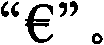
此外,通过对介电质层在两侧的厚度进行不同选择,甚至可以在两侧对颜色倾斜效果进行不同选择。Furthermore, by choosing different thicknesses of the dielectric layer on both sides, it is even possible to choose differently the color tilt effect on both sides.
具体地以下材料用于能够干涉的复合物的相应层:In particular the following materials are used for the respective layers of the interfering composite:
-对于反射层,反射性物质,尤其是金属如铝、银或铜;- for reflective layers, reflective substances, especially metals such as aluminium, silver or copper;
-对于介电质层,SiO2(二氧化硅)、ZrO2(二氧化锆)、MgF2(二氟化镁)或TiO2(二氧化钛)或其他透明物质,如非常薄的以及经极不均匀压印的透明清漆;- For the dielectric layer, SiO 2 (silicon dioxide), ZrO 2 (zirconium dioxide), MgF 2 (magnesium difluoride) or TiO 2 (titanium dioxide) or other transparent substances, such as very thin and Uniformly embossed clear varnish;
-对于不完全透射层,铬和/或镍、铁、银、金、或铬和/或镍、铁、银、金的合金,如因科镍TM(Ni-Cr-Fe)。- For the partially transmissive layer, chromium and/or nickel, iron, silver, gold, or alloys of chromium and/or nickel, iron, silver, gold, such as Inconel ™ (Ni-Cr-Fe).
在出版物WO 01/03945 A1、US 6,586,098 B1和US 6,699,313 B2中列出了能够干涉的复合物的各层用的其他材料以及特别是其各自的层厚。所引用的出版物的公开内容以引用方式并入本文。Further materials for the individual layers of the interfering composite and in particular their respective layer thicknesses are listed in the publications WO 01/03945 A1, US 6,586,098 B1 and US 6,699,313 B2. The disclosures of the cited publications are incorporated herein by reference.
然而,本发明不仅限于3层或5层薄层元件,并且可适用于产生可光变效果的许多一层或多层薄层元件。具体地,从现有技术中得知可光变的层,其从反射层起且在朝向观察者的方向上具有多于两个的层。而且,对于由这种可光变层制成且因此具有多于5个的层的薄层元件,本发明也是适用的。However, the invention is not limited to 3- or 5-layer thin-layer elements, but is applicable to many one- or multi-layer thin-layer elements producing optically variable effects. In particular, optically variable layers are known from the prior art which have more than two layers starting from the reflective layer in the direction towards the viewer. Furthermore, the invention is also applicable for thin-layer elements made of such an optically variable layer and thus having more than 5 layers.
例如可通过已知的印刷工艺或通过真空淀积如溅射、反应溅射、物理蒸气淀积或化学蒸气淀积在衬底上压印和/或真空淀积安全元件的各层。因此,将吸收材料、电介质和反射材料以各自堆叠或叠置层压印和/或蒸气淀积在衬底上。For example, the individual layers of the security element can be embossed and/or vacuum deposited on the substrate by known printing processes or by vacuum deposition such as sputtering, reactive sputtering, physical vapor deposition or chemical vapor deposition. Accordingly, the absorbing material, the dielectric and the reflective material are stamped and/or vapor deposited on the substrate in respective stacked or superimposed layers.
要求可考虑用于反射及不完全透射层的材料在非常薄的层中具有约5nm至100nm的层厚。优选地通过真空蒸气淀积应用这些层,其中通过加热装置例如电阻器或电子束使相关的金属加热并在真空中蒸发。然后金属在其上方移动的箔上沉淀为薄层。对于具有100nm与1μm之间层厚的介电质层的应用而言,真空蒸气淀积方法的各种变形同样是合适的。因此为了产生均匀的颜色,有必要使尤其是溅射或者还良好受控的热或电子束淀积方法所提供的层厚保持极度均匀。可替换地,还可通过印刷方法将透明电介质应用为呈透明墨水的形式。然而,这里,在涂覆过程中必需极度小心以确保所需的层厚均匀性,例如以±2%的容差。It is required that materials which can be considered for reflective and partially transmissive layers have a layer thickness of approximately 5 nm to 100 nm in very thin layers. These layers are preferably applied by vacuum vapor deposition, wherein the relevant metal is heated by heating means such as a resistor or an electron beam and evaporated in vacuum. The metal is then deposited as a thin layer on the foil moving over it. For the application of dielectric layers with a layer thickness of between 100 nm and 1 μm, variants of the vacuum vapor deposition method are likewise suitable. In order to produce uniform colours, it is therefore necessary to keep the layer thicknesses extremely uniform, especially by sputtering or also well-controlled thermal or electron beam deposition methods. Alternatively, the transparent dielectric can also be applied in the form of transparent ink by a printing method. Here, however, extreme care must be taken during the coating process to ensure the required layer thickness uniformity, for example with a tolerance of ±2%.
对于层的构成或脱金属,有利地使用已知的方法,如洗涤工艺、刻蚀、油烧蚀、再用剥离或激光脱金属。For layer formation or demetallization, known methods are advantageously used, such as washing processes, etching, oil ablation followed by lift-off or laser demetallization.
因此,有利地,通过蒸气淀积和脱金属产生从DE 10 2006 062 281得知的效果。Thus, advantageously, the effect known from
可以在正面和背面具有不同设计或者带有精确对准的安全元件的情况下,将安全箔与其他安全元件如荧光相结合。It is possible to combine security foils with other security elements such as fluorescence, with different designs on the front and back or with precisely aligned security elements.
根据本发明的安全元件优选地被应用在具有半透明且优选为透明的区域的数据载体上。这里,数据载体尤其是有价文件,如钞票、有价凭证、信用卡或身份卡、护照、证书及任何类似物、用于产品保护的标签物品、包装或其他元件。The security element according to the invention is preferably applied on a data carrier having translucent and preferably transparent regions. Data carriers here are in particular value documents such as bank notes, value documents, credit cards or identification cards, passports, certificates and the like, labeling items for product protection, packaging or other elements.
例如,半透明区域为呈贯通开口形式的窗,其被半透明且特别为透明的箔所覆盖。因而,根据本发明的安全元件从数据载体的两侧均可见。For example, the translucent area is a window in the form of a through opening, which is covered by a translucent and in particular transparent foil. Thus, the security element according to the invention is visible from both sides of the data carrier.
本文中“半透明”意指层是半透明的,意指层具有入射光的低于90%、优选地80%与20%之间的光透射。将透明理解为至少90%的光透射。如果安全元件被应用在具有小于90%光透射的半透明衬底例如非常薄的纸区域上,那么相应地对空隙的尺寸进行调整,这导致较小的对比以及颜色倾斜效果的较小强度。"Translucent" herein means that the layer is translucent, meaning that the layer has a light transmission of less than 90%, preferably between 80% and 20%, of the incident light. Transparent is understood to mean at least 90% light transmission. If the security element is applied on a translucent substrate with less than 90% light transmission, eg very thin paper areas, the size of the voids is adjusted accordingly, which results in less contrast and less intensity of the color tilt effect.
基于以下实施方式或示例以及附图,对本发明的优点进行了说明。所描述的单个特征和随后描述的示例性实施方式本身是创造性,但是结合起来也是创造性的。示例是优选实施方式,但是本发明绝不应限于这些优选实施方式。Advantages of the present invention are described based on the following embodiments or examples and the drawings. The individual features described and the exemplary embodiments described subsequently are inventive in themselves, but also in combination. The examples are preferred embodiments, but the invention should by no means be limited to these preferred embodiments.
此外,为了更好的领会,附图中的图示是非常示意性的且并不反应真实情况。尤其,附图中所示的比例并不与实际情况相对应且仅仅用作提高清晰性。此外,为了更好的领会,以下示例中所描述的实施方式被简化成基本的核心信息。为了转化为实际,可以使用显著更复杂的图样或图形。Furthermore, for better comprehension, the illustrations in the accompanying drawings are very schematic and do not reflect real situations. In particular, the scales shown in the figures do not correspond to reality and are used only to increase clarity. Furthermore, the implementations described in the following examples are simplified to basic core information for better comprehension. For practical purposes, significantly more complex patterns or graphics may be used.
附图说明Description of drawings
具体地,在附图中:Specifically, in the accompanying drawings:
图1示意性地示出了能够干涉的3层复合物,其包括具有空隙的不完全透射层以及具有多个呈网格状设置的空隙的反射层;Figure 1 schematically shows a 3-layer composite capable of interfering, comprising a partially transmissive layer with voids and a reflective layer with a plurality of voids arranged in a grid;
图2示意性地示出了能够干涉的3层复合物,其包括均具有多个呈网格状设置的空隙的不完全透射层以及反射层;Figure 2 schematically shows a 3-layer composite capable of interfering, comprising a partially transmissive layer and a reflective layer each having a plurality of voids arranged in a grid;
图3示意性地示出了能够干涉的5层复合物,其包括均具有多个呈网格状设置的空隙的两个不完全透射层以及中间反射层;Fig. 3 schematically shows a 5-layer composite capable of interfering, comprising two partially transmissive layers each having a plurality of voids arranged in a grid pattern and an intermediate reflective layer;
图4示意性地示出了根据图1的能够干涉的3层复合物,其中介电质层包括类似于不完全透射层的空隙;Fig. 4 schematically shows a 3-layer composite capable of interference according to Fig. 1, wherein the dielectric layer comprises voids similar to the partially transmissive layer;
图5示意性地示出了从反射层一侧观察的根据图1的能够干涉的3层复合物,其在反射层的呈网格状布置的空隙内具有呈星形的连续线;以及FIG. 5 schematically shows the interferometric 3-layer composite according to FIG. 1 , viewed from the reflective layer side, with star-shaped continuous lines in the grid-like arranged voids of the reflective layer; and
图6示意性地示出了具有相反顺序的根据图1的能够干涉的3层复合物,其被应用在具有压花结构的压花漆和衬底上。FIG. 6 schematically shows the interference-capable 3-layer composite according to FIG. 1 in reverse order, applied to an embossed varnish and substrate with an embossed structure.
具体实施方式Detailed ways
图1示出能够干涉的呈3层复合物形式的根据本发明的薄层复合物,其包括:不完全透射层1,具有空隙5;以及反射层3,具有多个呈网格状设置的空隙4。在不完全透射层1与反射层3之间且在整个区域上设有介电质层2。1 shows a thin-layer composite according to the invention in the form of a 3-layer composite capable of interfering, comprising: a partially
从不完全透射层1一侧观察到安全元件上的观察者在处于空隙5之外区域中的入射光(或反射光)中察觉到颜色倾斜(color tilt)效果。从而,当使安全元件从绿倾斜至红时,薄层复合物的颜色例如从绿色改变为红色。在空隙5的区域中,观察者在几乎所有观察角度下察觉到反射层3例如为灰色。然而,例如,如果将空隙5配置为数字“50”的形式,那么观察者在使安全元件倾斜时从几乎所有观察角度看到数字“50”周围的灰色数字“50”从绿色到红色的颜色倾斜效果。An observer looking at the security element from the side of the partially
呈网格状设置的空隙4被配置为圆形和/或线形,其中圆形空隙具有10微米至100微米、优选地具有30微米至50微米的直径,线形空隙具有30微米至70微米的宽度。The
与此相比,在透射光下,光穿过反射层3的多个空隙并穿过薄层复合物的剩余的层,使得观察者在空隙5之内以及之外均察觉不到任何颜色倾斜,而是察觉到均匀的灰色区。In contrast, in transmitted light, the light passes through the plurality of voids of the
如果观察者从反射层3一侧看到安全元件上,那么他在入射光下察觉到从反射层3反射的光以及在透射光下察觉到穿过空隙4的光。因此,观察者在入射光下察觉到类似金属的光亮区以及在透射光下察觉到均匀的灰色区。If an observer looks onto the security element from the side of the
依据不完全透射层1中的空隙5的配置,从安全元件的前侧观察,空隙5在透射光下也或多或少地显露。为了防止这种情况,根据图2,用多个空隙6代替空隙5。由此,在入射光下所察觉到的区域5与1之间的对比略微减小,反过来,这样导致区域5在透射光下更亮,使得其不再被观察者注意到。Depending on the configuration of the
通过将根据图1和图2的两个实施方式配置为根据图3的双面,可将这两个实施方式修改为这种效果。这里,在两个介电质层2与7之间存在包括网格形空隙的共同的反射层3。在相应的介电质层2和7与反射层3相反的一侧分别设有不完全透射层1和8。两个不完全透射层1和8包括根据图2的示例性实施方式的空隙。Both embodiments according to FIG. 1 and FIG. 2 can be modified to this effect by configuring them as double-sided according to FIG. 3 . Here, between the two
这里,相当有利的是,可从两侧看到颜色倾斜效果。另一方面,可以使介电质层2上的不完全透射层1以及介电质层7上的不完全透射层8在不同信息的情况下开放。例如,在入射光下从一侧显现出数字“50”,从相反侧在入射光下显现出符号
在不限制作用的光学效果的情况下,根据图4,还可以使介电质层2在不完全透射层1具有空隙的位置开放。在图4中以示例的方式且在根据图2的示例性实施方式中对此进行了示出。Without limiting the optical effect of the action, according to FIG. 4 , it is also possible to leave the
图5示出从反射层3一侧观察的在透射光下的根据图1的能够干涉的3层复合物。呈星形的细的连续线位于反射层的呈网格状设置的空隙4内。为了有效,线具有0.1mm至5mm的宽度,使得该线在透射光下可被充分地注意到。在入射光下,该线无法被观察者注意到,这几乎与其线宽无关,因为入射光在反射层整个面积上的区域与被设置为开放的反射层的区域之间可被注意到的颜色倾斜效果实际上没有不同。因此,观察者在透射光下除了看到关于图1描述的效果之外还看到星形以及在入射光下仅仅看到关于图1描述的效果而看不到星形。FIG. 5 shows the interference-capable 3-layer composite according to FIG. 1 viewed from the
相当有利的是,根据本发明的安全元件与已知的旋光性微观结构例如衍射模压全息图、零阶透射光栅、折射微观结构如炫耀光栅以及类似相结合。Quite advantageously, the security element according to the invention is combined with known optically active microstructures such as diffractive embossed holograms, zero-order transmission gratings, refractive microstructures such as blazed gratings and the like.
图6以示例的方式示出这种与模压全息图的结合,其中选取了以下能够干涉的3层复合物:反射层3,位于介电质层1上并具有呈网格状设置的空隙;以及不完全透射层1,其包括在两个区域中设置成网格状的空隙。该复合物被应用在具有衍射压花结构和衬底10的压花漆9上。FIG. 6 shows by way of example such a combination with an embossed hologram, in which the following 3-layer composite capable of interfering has been chosen: a
该安全特征从前侧示出例如从绛红色到绿色的第一颜色倾斜效果,以及从后侧示出例如从绿色到绛红色的第二颜色倾斜效果。除此之外,在入射光下,从后侧以及从前侧可以在颜料层内看到不同的图画信息,例如
显然,根据图6的示例性实施方式本身可通过压花层上的颠倒的层顺序组成,在序列的压花漆中,这意味着位于具有衍射压花结构的压花漆9和衬底10上的压花漆、反射层、介电质层和不完全透射层。同样,与图3相对应的实施方式也是可能的,这相应地意味着在压花漆9的两侧可以形成可光变薄层元件。Obviously, the exemplary embodiment according to FIG. 6 can itself be composed by a reversed layer sequence on the embossed layer, in sequential embossed varnishes, this means that between the embossed lacquer 9 and the
Claims (16)
Priority Applications (1)
| Application Number | Priority Date | Filing Date | Title |
|---|---|---|---|
| CN201510594339.3A CN105172419B (en) | 2008-06-12 | 2009-05-28 | With can light dependent element safety element |
Applications Claiming Priority (3)
| Application Number | Priority Date | Filing Date | Title |
|---|---|---|---|
| DE102008028187.5 | 2008-06-12 | ||
| DE102008028187A DE102008028187A1 (en) | 2008-06-12 | 2008-06-12 | Security element with optically variable element. |
| PCT/EP2009/003791 WO2009149831A2 (en) | 2008-06-12 | 2009-05-28 | Security element comprising an optically variable element |
Related Child Applications (1)
| Application Number | Title | Priority Date | Filing Date |
|---|---|---|---|
| CN201510594339.3A Division CN105172419B (en) | 2008-06-12 | 2009-05-28 | With can light dependent element safety element |
Publications (1)
| Publication Number | Publication Date |
|---|---|
| CN102112325A true CN102112325A (en) | 2011-06-29 |
Family
ID=41317777
Family Applications (2)
| Application Number | Title | Priority Date | Filing Date |
|---|---|---|---|
| CN201510594339.3A Active CN105172419B (en) | 2008-06-12 | 2009-05-28 | With can light dependent element safety element |
| CN2009801218792A Pending CN102112325A (en) | 2008-06-12 | 2009-05-28 | Security element with optically variable element |
Family Applications Before (1)
| Application Number | Title | Priority Date | Filing Date |
|---|---|---|---|
| CN201510594339.3A Active CN105172419B (en) | 2008-06-12 | 2009-05-28 | With can light dependent element safety element |
Country Status (6)
| Country | Link |
|---|---|
| US (1) | US9415622B2 (en) |
| EP (1) | EP2300241B1 (en) |
| CN (2) | CN105172419B (en) |
| CA (1) | CA2726431C (en) |
| DE (1) | DE102008028187A1 (en) |
| WO (1) | WO2009149831A2 (en) |
Cited By (4)
| Publication number | Priority date | Publication date | Assignee | Title |
|---|---|---|---|---|
| CN102501500A (en) * | 2011-12-09 | 2012-06-20 | 中钞特种防伪科技有限公司 | Optical anti-counterfeit element |
| CN107107651A (en) * | 2014-09-17 | 2017-08-29 | 法商亚宙维金斯安全公司 | secure element |
| CN107921810A (en) * | 2015-05-27 | 2018-04-17 | 捷德货币技术有限责任公司 | The Security element of optically-variable |
| CN109863036A (en) * | 2016-11-07 | 2019-06-07 | 捷德货币技术有限责任公司 | Security element with optically variable see-through element |
Families Citing this family (44)
| Publication number | Priority date | Publication date | Assignee | Title |
|---|---|---|---|---|
| DE102006058513A1 (en) | 2006-12-12 | 2008-06-19 | Giesecke & Devrient Gmbh | Drainage screen and process for its production |
| DE102007029204A1 (en) * | 2007-06-25 | 2009-01-08 | Giesecke & Devrient Gmbh | security element |
| DE102007029203A1 (en) | 2007-06-25 | 2009-01-08 | Giesecke & Devrient Gmbh | security element |
| DE102007061828A1 (en) * | 2007-12-20 | 2009-06-25 | Giesecke & Devrient Gmbh | Security element and method for its production |
| DE102007061827A1 (en) * | 2007-12-20 | 2009-06-25 | Giesecke & Devrient Gmbh | Security element and method for its production |
| DE102007061979A1 (en) | 2007-12-21 | 2009-06-25 | Giesecke & Devrient Gmbh | security element |
| DE102007062089A1 (en) | 2007-12-21 | 2009-07-02 | Giesecke & Devrient Gmbh | Method for creating a microstructure |
| DE102008008685A1 (en) * | 2008-02-12 | 2009-08-13 | Giesecke & Devrient Gmbh | Security element and method for its production |
| DE102008009296A1 (en) * | 2008-02-15 | 2009-08-20 | Giesecke & Devrient Gmbh | Security element and method for its production |
| DE102008013167A1 (en) | 2008-03-07 | 2009-09-10 | Giesecke & Devrient Gmbh | Security element and method for its production |
| DE102008016795A1 (en) | 2008-04-02 | 2009-10-08 | Giesecke & Devrient Gmbh | Method for producing a micro-optical moiré magnification arrangement |
| DE102008028187A1 (en) | 2008-06-12 | 2009-12-17 | Giesecke & Devrient Gmbh | Security element with optically variable element. |
| DE102008029638A1 (en) * | 2008-06-23 | 2009-12-24 | Giesecke & Devrient Gmbh | security element |
| DE102008031325A1 (en) | 2008-07-02 | 2010-01-07 | Giesecke & Devrient Gmbh | Security element and method for its production |
| DE102008032224A1 (en) * | 2008-07-09 | 2010-01-14 | Giesecke & Devrient Gmbh | security element |
| DE102008037128A1 (en) | 2008-08-08 | 2010-02-11 | Giesecke & Devrient Gmbh | Security element with incident and transmitted light information |
| DE102008046511A1 (en) * | 2008-09-10 | 2010-03-11 | Giesecke & Devrient Gmbh | representation arrangement |
| DE102009035413A1 (en) | 2009-07-31 | 2011-02-03 | Giesecke & Devrient Gmbh | Identification document with a personalized visual identification and method for its production |
| DE102009041583A1 (en) | 2009-09-15 | 2011-03-17 | Giesecke & Devrient Gmbh | Thin-film element with interference layer structure |
| DE102009042022A1 (en) | 2009-09-21 | 2011-03-24 | Giesecke & Devrient Gmbh | Elongated security element with machine-readable magnetic areas |
| DE102010031713A1 (en) * | 2010-07-21 | 2012-01-26 | Giesecke & Devrient Gmbh | Optically variable security element with tilting image |
| US10124620B2 (en) * | 2012-03-13 | 2018-11-13 | Graphic Security Systems Corporation | Multi-image optical device |
| DE102012018434A1 (en) | 2012-09-18 | 2014-03-20 | Giesecke & Devrient Gmbh | Optically variable security element with additional open / see-through effect |
| GB201316348D0 (en) * | 2013-09-13 | 2013-10-30 | Andrews & Wykeham Ltd | Security laminate/foil |
| DE102014001688A1 (en) | 2014-02-07 | 2015-08-13 | Giesecke & Devrient Gmbh | Production of a security element with color change properties |
| BR112016029755A2 (en) | 2014-06-23 | 2017-08-22 | Carbon Inc | methods of producing three-dimensional objects from materials having multiple hardening mechanisms |
| FR3026988B1 (en) * | 2014-10-13 | 2021-07-02 | Arjowiggins Security | SECURITY ELEMENT FOR SECURE DOCUMENT |
| DE102015003665A1 (en) | 2015-03-20 | 2016-09-22 | Giesecke & Devrient Gmbh | security element |
| DE102015004027A1 (en) | 2015-03-27 | 2016-09-29 | Giesecke & Devrient Gmbh | Security element with effect pigments and an embossed structure and method for its production |
| DE102015005446A1 (en) | 2015-04-28 | 2016-11-03 | Giesecke & Devrient Gmbh | Security element with multilayer structure |
| AU2015100671B4 (en) * | 2015-05-21 | 2015-10-29 | Ccl Secure Pty Ltd | Diffractive optical device having embedded light source mechanism |
| DE102015009164A1 (en) | 2015-07-14 | 2017-01-19 | Giesecke & Devrient Gmbh | Disk with breakthrough area |
| DE102015009584A1 (en) * | 2015-07-23 | 2017-02-09 | Giesecke & Devrient Gmbh | Security element and method for its production |
| DE102015010334A1 (en) * | 2015-08-07 | 2017-02-09 | Giesecke & Devrient Gmbh | security element |
| WO2017041085A1 (en) * | 2015-09-04 | 2017-03-09 | President And Fellows Of Harvard College | Modifying optical properties of thin film structures using an absorbing element |
| DE102016014662A1 (en) | 2016-12-09 | 2018-06-14 | Giesecke+Devrient Currency Technology Gmbh | value document |
| DE102017001598A1 (en) | 2017-02-17 | 2018-08-23 | Giesecke+Devrient Currency Technology Gmbh | Security element transfer material and method of making same |
| AU2017101291B4 (en) * | 2017-09-21 | 2018-03-08 | Ccl Secure Pty Ltd | Optically variable three dimensional moiré device |
| GB2568077A (en) * | 2017-11-03 | 2019-05-08 | De La Rue Int Ltd | Security document and method of manufacture thereof |
| DE102018002306A1 (en) | 2018-03-21 | 2019-09-26 | Giesecke+Devrient Currency Technology Gmbh | A method of manufacturing a security element transfer material and security element transfer material |
| DE102018005447A1 (en) * | 2018-07-09 | 2020-01-09 | Giesecke+Devrient Currency Technology Gmbh | Optically variable security element with reflective surface area |
| DE102019006977A1 (en) | 2019-10-08 | 2021-04-08 | Giesecke+Devrient Currency Technology Gmbh | Security element transfer material, method of making the same and use |
| DE102020004236A1 (en) | 2020-07-14 | 2022-01-20 | Giesecke+Devrient Currency Technology Gmbh | document of value |
| DE102022133325A1 (en) * | 2022-12-14 | 2024-06-20 | Giesecke+Devrient Currency Technology Gmbh | Optically variable security element with 5-layer stack, data carrier and manufacturing process |
Citations (5)
| Publication number | Priority date | Publication date | Assignee | Title |
|---|---|---|---|---|
| US4434010A (en) * | 1979-12-28 | 1984-02-28 | Optical Coating Laboratory, Inc. | Article and method for forming thin film flakes and coatings |
| GB2250474A (en) * | 1990-12-04 | 1992-06-10 | Portals Ltd | Security articles |
| FR2830791A1 (en) * | 2001-10-15 | 2003-04-18 | Finega | Document identifiable under UV light by moire effect and contrast has overprinted motifs in visible and invisible inks |
| WO2003095228A1 (en) * | 2002-05-14 | 2003-11-20 | Leonhard Kurz Gmbh & Co. Kg | Optically variable element comprising a sequence of thin-film layers |
| DE102004039355A1 (en) * | 2004-08-12 | 2006-02-23 | Giesecke & Devrient Gmbh | Security element and method for its production |
Family Cites Families (60)
| Publication number | Priority date | Publication date | Assignee | Title |
|---|---|---|---|---|
| GB2282563A (en) | 1993-10-07 | 1995-04-12 | Central Research Lab Ltd | A composite image arrangement for documents of value |
| US6761959B1 (en) | 1999-07-08 | 2004-07-13 | Flex Products, Inc. | Diffractive surfaces with color shifting backgrounds |
| DE19941295A1 (en) * | 1999-08-31 | 2001-03-01 | Giesecke & Devrient Gmbh | Security element |
| JP2003520986A (en) * | 2000-01-21 | 2003-07-08 | フレックス プロダクツ インコーポレイテッド | Optical modulation security device |
| US6586098B1 (en) | 2000-07-27 | 2003-07-01 | Flex Products, Inc. | Composite reflective flake based pigments comprising reflector layers on bothside of a support layer |
| GB2375078A (en) * | 2001-04-30 | 2002-11-06 | Rue De Int Ltd | Security substrate with indicia only viewable in transmitted light |
| DE10226114A1 (en) | 2001-12-21 | 2003-07-03 | Giesecke & Devrient Gmbh | Security element for security papers and documents of value |
| DE10206357A1 (en) * | 2002-02-14 | 2003-08-28 | Giesecke & Devrient Gmbh | Security element and security document with such a security element |
| DE10216562C1 (en) * | 2002-04-05 | 2003-12-11 | Ovd Kinegram Ag Zug | Security element with micro and macro structures |
| DE10319232A1 (en) * | 2003-04-28 | 2004-11-18 | Giesecke & Devrient Gmbh | Flat security element and manufacturing method for the same |
| EP1744904B2 (en) * | 2004-04-30 | 2019-11-06 | Giesecke+Devrient Currency Technology GmbH | Sheeting and methods for the production thereof |
| DE102004021247A1 (en) * | 2004-04-30 | 2005-11-24 | Giesecke & Devrient Gmbh | Security element and method for its production |
| DE102004021246A1 (en) | 2004-04-30 | 2005-11-24 | Giesecke & Devrient Gmbh | Security element and method for its production |
| EP2287011B1 (en) * | 2004-04-30 | 2017-06-28 | Giesecke & Devrient GmbH | Security element and process for manufacturing it |
| DE102004022079A1 (en) | 2004-05-05 | 2005-11-24 | Giesecke & Devrient Gmbh | Value document with serial number |
| DE102004022080A1 (en) | 2004-05-05 | 2005-11-24 | Giesecke & Devrient Gmbh | Value document with visually recognizable markings |
| DE102004035979A1 (en) | 2004-07-14 | 2006-02-02 | Giesecke & Devrient Gmbh | Security element and method for its production |
| DE102004038542A1 (en) * | 2004-08-06 | 2006-02-23 | Giesecke & Devrient Gmbh | Data carrier with security element and method for its production |
| WO2006018171A2 (en) | 2004-08-12 | 2006-02-23 | Giesecke & Devrient Gmbh | Security element comprising a support |
| DE102004049118A1 (en) | 2004-10-07 | 2006-04-13 | Giesecke & Devrient Gmbh | Security element and method for its production |
| DE102004056553B4 (en) | 2004-11-23 | 2013-03-14 | Giesecke & Devrient Gmbh | Security arrangement for security documents and method for producing the security documents |
| DE102004063217A1 (en) | 2004-12-29 | 2006-07-13 | Giesecke & Devrient Gmbh | Security feature for value documents |
| DE102005028162A1 (en) * | 2005-02-18 | 2006-12-28 | Giesecke & Devrient Gmbh | Security element for protecting valuable objects, e.g. documents, includes focusing components for enlarging views of microscopic structures as one of two authenication features |
| DE102005045566A1 (en) * | 2005-03-23 | 2006-09-28 | Giesecke & Devrient Gmbh | Multi-layer security paper |
| DE102005022018A1 (en) * | 2005-05-12 | 2006-11-16 | Giesecke & Devrient Gmbh | Security paper and process for its production |
| DE102005025095A1 (en) * | 2005-06-01 | 2006-12-07 | Giesecke & Devrient Gmbh | Data carrier and method for its production |
| DE102005032815A1 (en) * | 2005-07-12 | 2007-01-18 | Giesecke & Devrient Gmbh | Method for producing a security paper, paper screen and forming element for paper screen |
| DE102005032997A1 (en) * | 2005-07-14 | 2007-01-18 | Giesecke & Devrient Gmbh | Lattice image and method for its production |
| CA2564764C (en) * | 2005-10-25 | 2014-05-13 | Jds Uniphase Corporation | Patterned optical structures with enhanced security feature |
| DE102005061749A1 (en) * | 2005-12-21 | 2007-07-05 | Giesecke & Devrient Gmbh | Optically variable security element for making valuable objects safe has an achromatic reflecting micro-structure taking the form of a mosaic made from achromatic reflecting mosaic elements |
| DE102005062132A1 (en) | 2005-12-23 | 2007-07-05 | Giesecke & Devrient Gmbh | Security unit e.g. seal, for e.g. valuable document, has motive image with planar periodic arrangement of micro motive units, and periodic arrangement of lens for moire magnified observation of motive units |
| DE102006015023A1 (en) | 2006-03-31 | 2007-10-04 | Giesecke & Devrient Gmbh | Security element for security papers, value documents, has relief structure, which is formed on basis of cholesteric, liquid crystalline polymer material and top layer contains reflecting or high-refracting layer |
| DE102006029852A1 (en) | 2006-06-27 | 2008-01-03 | Giesecke & Devrient Gmbh | Method of applying a microstructure, mold and microstructured article |
| DE102006029850A1 (en) | 2006-06-27 | 2008-01-03 | Giesecke & Devrient Gmbh | security element |
| DE102006039305A1 (en) * | 2006-07-21 | 2008-01-24 | Giesecke & Devrient Gmbh | Security thread with optically variable security feature |
| DE102006050047A1 (en) * | 2006-10-24 | 2008-04-30 | Giesecke & Devrient Gmbh | Transparent security element for security papers, data carrier, particularly valuable documents such as bank note, identification card and for falsification of goods, has transparent substrate and marking layer applied on substrate |
| DE102006055680A1 (en) | 2006-11-23 | 2008-05-29 | Giesecke & Devrient Gmbh | Security element with metallization |
| DE102006058513A1 (en) * | 2006-12-12 | 2008-06-19 | Giesecke & Devrient Gmbh | Drainage screen and process for its production |
| DE102006062281A1 (en) | 2006-12-22 | 2008-06-26 | Giesecke & Devrient Gmbh | Substrate for use with safety feature, has pigments of optically variable color of safety features that are irreversibly changed in partition by electromagnetic radiation |
| DE102007029204A1 (en) * | 2007-06-25 | 2009-01-08 | Giesecke & Devrient Gmbh | security element |
| DE102007029203A1 (en) | 2007-06-25 | 2009-01-08 | Giesecke & Devrient Gmbh | security element |
| DE102007034716A1 (en) | 2007-07-23 | 2009-01-29 | Giesecke & Devrient Gmbh | security element |
| DE102007039591A1 (en) | 2007-08-22 | 2009-02-26 | Giesecke & Devrient Gmbh | grid image |
| DE102007061827A1 (en) * | 2007-12-20 | 2009-06-25 | Giesecke & Devrient Gmbh | Security element and method for its production |
| DE102007061828A1 (en) * | 2007-12-20 | 2009-06-25 | Giesecke & Devrient Gmbh | Security element and method for its production |
| DE102007062089A1 (en) * | 2007-12-21 | 2009-07-02 | Giesecke & Devrient Gmbh | Method for creating a microstructure |
| DE102007061979A1 (en) * | 2007-12-21 | 2009-06-25 | Giesecke & Devrient Gmbh | security element |
| DE102008008685A1 (en) | 2008-02-12 | 2009-08-13 | Giesecke & Devrient Gmbh | Security element and method for its production |
| DE102008009296A1 (en) * | 2008-02-15 | 2009-08-20 | Giesecke & Devrient Gmbh | Security element and method for its production |
| DE102008013167A1 (en) | 2008-03-07 | 2009-09-10 | Giesecke & Devrient Gmbh | Security element and method for its production |
| DE102008016795A1 (en) | 2008-04-02 | 2009-10-08 | Giesecke & Devrient Gmbh | Method for producing a micro-optical moiré magnification arrangement |
| DE102008027952A1 (en) | 2008-06-12 | 2009-12-17 | Giesecke & Devrient Gmbh | Security element with screened layer of raster elements |
| DE102008028187A1 (en) | 2008-06-12 | 2009-12-17 | Giesecke & Devrient Gmbh | Security element with optically variable element. |
| DE102008029638A1 (en) * | 2008-06-23 | 2009-12-24 | Giesecke & Devrient Gmbh | security element |
| DE102008031325A1 (en) * | 2008-07-02 | 2010-01-07 | Giesecke & Devrient Gmbh | Security element and method for its production |
| DE102008032224A1 (en) * | 2008-07-09 | 2010-01-14 | Giesecke & Devrient Gmbh | security element |
| DE102008046511A1 (en) * | 2008-09-10 | 2010-03-11 | Giesecke & Devrient Gmbh | representation arrangement |
| DE102009035413A1 (en) | 2009-07-31 | 2011-02-03 | Giesecke & Devrient Gmbh | Identification document with a personalized visual identification and method for its production |
| DE102009041583A1 (en) * | 2009-09-15 | 2011-03-17 | Giesecke & Devrient Gmbh | Thin-film element with interference layer structure |
| DE102009042022A1 (en) * | 2009-09-21 | 2011-03-24 | Giesecke & Devrient Gmbh | Elongated security element with machine-readable magnetic areas |
-
2008
- 2008-06-12 DE DE102008028187A patent/DE102008028187A1/en not_active Withdrawn
-
2009
- 2009-05-28 CN CN201510594339.3A patent/CN105172419B/en active Active
- 2009-05-28 WO PCT/EP2009/003791 patent/WO2009149831A2/en not_active Ceased
- 2009-05-28 US US12/997,323 patent/US9415622B2/en not_active Expired - Fee Related
- 2009-05-28 CA CA2726431A patent/CA2726431C/en active Active
- 2009-05-28 CN CN2009801218792A patent/CN102112325A/en active Pending
- 2009-05-28 EP EP09761394.7A patent/EP2300241B1/en active Active
Patent Citations (5)
| Publication number | Priority date | Publication date | Assignee | Title |
|---|---|---|---|---|
| US4434010A (en) * | 1979-12-28 | 1984-02-28 | Optical Coating Laboratory, Inc. | Article and method for forming thin film flakes and coatings |
| GB2250474A (en) * | 1990-12-04 | 1992-06-10 | Portals Ltd | Security articles |
| FR2830791A1 (en) * | 2001-10-15 | 2003-04-18 | Finega | Document identifiable under UV light by moire effect and contrast has overprinted motifs in visible and invisible inks |
| WO2003095228A1 (en) * | 2002-05-14 | 2003-11-20 | Leonhard Kurz Gmbh & Co. Kg | Optically variable element comprising a sequence of thin-film layers |
| DE102004039355A1 (en) * | 2004-08-12 | 2006-02-23 | Giesecke & Devrient Gmbh | Security element and method for its production |
Cited By (6)
| Publication number | Priority date | Publication date | Assignee | Title |
|---|---|---|---|---|
| CN102501500A (en) * | 2011-12-09 | 2012-06-20 | 中钞特种防伪科技有限公司 | Optical anti-counterfeit element |
| CN102501500B (en) * | 2011-12-09 | 2014-09-24 | 中钞特种防伪科技有限公司 | Optical anti-counterfeit element |
| CN107107651A (en) * | 2014-09-17 | 2017-08-29 | 法商亚宙维金斯安全公司 | secure element |
| CN107107651B (en) * | 2014-09-17 | 2019-03-12 | 法商亚宙维金斯安全公司 | Secure element, security document, and method of authenticating a security document |
| CN107921810A (en) * | 2015-05-27 | 2018-04-17 | 捷德货币技术有限责任公司 | The Security element of optically-variable |
| CN109863036A (en) * | 2016-11-07 | 2019-06-07 | 捷德货币技术有限责任公司 | Security element with optically variable see-through element |
Also Published As
| Publication number | Publication date |
|---|---|
| EP2300241B1 (en) | 2015-12-02 |
| US9415622B2 (en) | 2016-08-16 |
| WO2009149831A2 (en) | 2009-12-17 |
| CN105172419A (en) | 2015-12-23 |
| EP2300241A2 (en) | 2011-03-30 |
| US20110101670A1 (en) | 2011-05-05 |
| WO2009149831A3 (en) | 2010-10-21 |
| DE102008028187A1 (en) | 2009-12-17 |
| CA2726431C (en) | 2017-12-05 |
| CA2726431A1 (en) | 2009-12-17 |
| CN105172419B (en) | 2019-03-19 |
Similar Documents
| Publication | Publication Date | Title |
|---|---|---|
| US9415622B2 (en) | Security element with optically variable element | |
| CA2726432C (en) | Security element having a screened layer composed of grid elements | |
| JP4888545B2 (en) | Display and printed information | |
| US9731539B2 (en) | Security devices | |
| US10007233B2 (en) | Decorative element and security document comprising a decorative element | |
| RU2514589C2 (en) | Thin-film element having interference layer structure | |
| CN101011916B (en) | Patterned optical structures with enhanced security feature | |
| US20110079997A1 (en) | Security Element and Method for the Production Thereof | |
| CN110520304B (en) | Anti-counterfeiting element with relief structure and production method thereof | |
| AU2017243171B2 (en) | Optically variable device and method of forming thereof | |
| CN115320274B (en) | Security elements with volume holograms and additional effects | |
| AU2023273118B2 (en) | Value document, and method for producing a value document | |
| HK1171208B (en) | Parallax effect security element | |
| HK1171208A1 (en) | Parallax effect security element | |
| HK1243978B (en) | Security element with effect pigments and an embossing structure and method for the production thereof |
Legal Events
| Date | Code | Title | Description |
|---|---|---|---|
| C06 | Publication | ||
| PB01 | Publication | ||
| C10 | Entry into substantive examination | ||
| SE01 | Entry into force of request for substantive examination | ||
| C12 | Rejection of a patent application after its publication | ||
| RJ01 | Rejection of invention patent application after publication |
Application publication date: 20110629 |