CN102042116A - Engine cooling water jacket - Google Patents
Engine cooling water jacket Download PDFInfo
- Publication number
- CN102042116A CN102042116A CN201010603738.9A CN201010603738A CN102042116A CN 102042116 A CN102042116 A CN 102042116A CN 201010603738 A CN201010603738 A CN 201010603738A CN 102042116 A CN102042116 A CN 102042116A
- Authority
- CN
- China
- Prior art keywords
- water jacket
- cylinder
- water
- flow channel
- flows
- Prior art date
- Legal status (The legal status is an assumption and is not a legal conclusion. Google has not performed a legal analysis and makes no representation as to the accuracy of the status listed.)
- Pending
Links
- 239000000498 cooling water Substances 0.000 title claims abstract description 33
- XLYOFNOQVPJJNP-UHFFFAOYSA-N water Substances O XLYOFNOQVPJJNP-UHFFFAOYSA-N 0.000 claims abstract description 158
- 239000000110 cooling liquid Substances 0.000 abstract description 4
- 239000002826 coolant Substances 0.000 description 24
- 238000001816 cooling Methods 0.000 description 18
- 239000000446 fuel Substances 0.000 description 10
- 238000000034 method Methods 0.000 description 4
- 238000002485 combustion reaction Methods 0.000 description 3
- 230000017525 heat dissipation Effects 0.000 description 3
- 230000009286 beneficial effect Effects 0.000 description 1
- 210000000476 body water Anatomy 0.000 description 1
- 230000007423 decrease Effects 0.000 description 1
- 238000010586 diagram Methods 0.000 description 1
- 230000000694 effects Effects 0.000 description 1
- 238000004519 manufacturing process Methods 0.000 description 1
Images


Landscapes
- Cylinder Crankcases Of Internal Combustion Engines (AREA)
Abstract
Description
技术领域technical field
本发明涉及汽车冷却系统技术领域,具体涉及一种发动机冷却水套。The invention relates to the technical field of automobile cooling systems, in particular to an engine cooling water jacket.
背景技术Background technique
随着内燃机技术的发展,冷却系统也发生了巨大改变,特别是水冷式发动机,冷却循环控制越来精确,这样对降低排放和油耗有着显著的效果。目前存在的几种常见的强制循环式冷却系统:第一种是经过散热器的冷却液直接由水泵泵入发动机本体进行冷却,然后直接回到散热器。这种冷却系统结构形势简单,无轮在什么工况,冷却液都一直通过散热器进行冷却,因此在某些工况下存在过冷问题,该种形式的冷却系统对排放和油耗的影响较大。第二种是在发动机本体的出水口的水泵的入水口之间设置调温器,调温器随冷却液的温度的变化而开启或关闭。当发动机冷却液的温度较低时,调温器关闭,水循环只经过发动机本体,不经过散热器,该循环方式称为小循环。这样能很快提升冷却液的温度,改善燃烧,降低油耗和排放。当冷却液的温度较高时,调温器开启,使得通过发动机本体的冷却液必须经过散热器散热后才能再次泵入发动机本体冷却,该循环方式称为大循环。这种形式的冷却系统较第一种形式的控制精度更高,在温度较低时,启用小循环,在温度较高时,启用大循环,使发动机工作在理想的温度区间,从而降低排放和油耗,因此该形式的冷却系统被广泛采用。With the development of internal combustion engine technology, the cooling system has also undergone tremendous changes, especially for water-cooled engines, the cooling cycle control is more and more precise, which has a significant effect on reducing emissions and fuel consumption. Several common forced circulation cooling systems exist at present: the first is that the coolant through the radiator is directly pumped into the engine body by the water pump for cooling, and then directly returns to the radiator. The structure of this cooling system is simple. In any working condition without wheels, the coolant is always cooled through the radiator. Therefore, under certain working conditions, there is a problem of overcooling. This type of cooling system has a greater impact on emissions and fuel consumption. big. The second is to arrange a thermostat between the water inlet of the water pump of the water outlet of the engine body, and the thermostat is opened or closed according to the temperature change of the coolant. When the temperature of the engine coolant is low, the thermostat is closed, and the water circulation only passes through the engine body and does not pass through the radiator. This circulation method is called a small circulation. This quickly raises the temperature of the coolant, improves combustion, reduces fuel consumption and emissions. When the temperature of the coolant is high, the thermostat is turned on, so that the coolant passing through the engine body must pass through the radiator to dissipate heat before being pumped into the engine body for cooling again. This circulation method is called a large cycle. This type of cooling system has higher control precision than the first type. When the temperature is low, a small cycle is enabled, and when the temperature is high, a large cycle is enabled to make the engine work in an ideal temperature range, thereby reducing emissions and Fuel consumption, so this form of cooling system is widely used.
采用第二种形式的冷却系统中,常见的发动机本体水套设计是冷却液由水泵泵入气缸体的水套中,然后通过缸垫进入气缸盖的水套中,然后从气缸盖的水套的一端流出,这种水套的结构简单,控制简单,但是水套中的冷却液的流速均匀性较差,冷却效率偏低。随着技术的发展,又出现双调温器控制系统,冷却液由水泵分别泵入气缸体和气缸盖的水套中,然后分别从气缸体和气缸盖的水套的出口流出,通过各自的调温器进行大小循环的控制,这种循环系统,能明显改善水套中的冷却液的流速的不均匀性,提高冷却效率,但是该冷却系统结构复杂,制造成本高,因此目前应用不太广泛。In the second form of cooling system, the common design of the water jacket of the engine body is that the coolant is pumped into the water jacket of the cylinder block by the water pump, and then enters the water jacket of the cylinder head through the cylinder gasket, and then flows from the water jacket of the cylinder head. This water jacket has a simple structure and simple control, but the flow rate uniformity of the coolant in the water jacket is poor, and the cooling efficiency is low. With the development of technology, a double thermostat control system appeared again. The coolant is pumped into the water jackets of the cylinder block and the cylinder head respectively by the water pump, and then flows out from the outlets of the water jackets of the cylinder block and the cylinder head respectively, through their respective The thermostat controls the large and small circulation. This circulation system can obviously improve the inhomogeneity of the flow rate of the coolant in the water jacket and improve the cooling efficiency. However, the cooling system has a complex structure and high manufacturing cost, so it is not widely used at present. widely.
发明内容Contents of the invention
本发明的目的是提出一种结构简单,体积小,流速均匀,压损低的发动机冷却水套。The purpose of the present invention is to propose an engine cooling water jacket with simple structure, small volume, uniform flow velocity and low pressure loss.
本发明的发动机冷却水套包括气缸体水套和气缸盖水套,所述气缸体水套由两处挡板隔开而形成第一流道和第二流道,所述第一流道连接进水口并且流经排气侧,所述第二流道连接出水口并且流经进气侧,所述第一流道和第二流道均通过气缸垫上的过水孔与气缸盖水套连通。The engine cooling water jacket of the present invention includes a cylinder block water jacket and a cylinder head water jacket, the cylinder block water jacket is separated by two baffles to form a first flow channel and a second flow channel, and the first flow channel is connected to the water inlet And flow through the exhaust side, the second flow channel is connected to the water outlet and flows through the intake side, and both the first flow channel and the second flow channel communicate with the cylinder head water jacket through the water hole on the cylinder gasket.
无论是传统的单缸直列发动机还是V型发动机或其他结构的发动机,本发明的主旨是在发热量较高的一侧设置与进水口连接的第一流道,在发热量较低的一侧设置与出水口连接的第二流道,第一流道和第二流道均通过气缸垫上的过水孔与气缸盖水套连通。冷却液主要从进水口流入第一流道并流经排气侧,并且通过气缸垫上一侧的过水孔流入气缸盖水套,然后经过气缸垫上另一侧的过水孔流入第二流道并流经进气侧,最后流出出水口。这样使得整个发动机冷却水套的冷却液流速更均匀,从而减小气缸孔热态下的变形量,降低活塞环的张力,从而减小摩擦功,提高发动机动力性能,降低油耗;本发明的气缸垫上的过水孔可以根据实际需要布置第一流道和第二流道的过水孔的大小和位置,不受传统水套设计气缸孔的影响,可以整体增大缸垫上的过水孔的通流面积,以降低整个水套的压损,从而降低对水泵的性能要求,以降低油耗。本发明应用在增压机上时,由于增压机排气侧的温度更高,需要的散热量更大,因此冷却水套的第一流道主要流经排气侧,第二流道主要流经进气侧;当本发明应用在自然吸气时,可将第一流道设置在进气侧,这样有利于增大进气量,提高发动机性能。Whether it is a traditional single-cylinder in-line engine or a V-type engine or an engine of other structures, the gist of the present invention is to set the first runner connected to the water inlet on the side with higher calorific value, and set the The second flow channel connected with the water outlet, the first flow channel and the second flow channel communicate with the water jacket of the cylinder head through the water hole on the cylinder gasket. The coolant mainly flows into the first flow channel from the water inlet and flows through the exhaust side, and flows into the cylinder head water jacket through the water hole on one side of the cylinder gasket, and then flows into the second flow channel through the water hole on the other side of the cylinder gasket. Flows through the intake side and finally out the outlet. This makes the coolant flow rate of the entire engine cooling water jacket more uniform, thereby reducing the deformation of the cylinder bore in a thermal state, reducing the tension of the piston ring, thereby reducing friction work, improving engine power performance, and reducing fuel consumption; the cylinder of the present invention The size and position of the water holes of the first flow channel and the second flow channel can be arranged according to the actual needs of the water holes on the pad. It is not affected by the cylinder hole of the traditional water jacket design, and the flow of the water holes on the cylinder pad can be increased as a whole. The flow area is reduced to reduce the pressure loss of the entire water jacket, thereby reducing the performance requirements of the water pump and reducing fuel consumption. When the present invention is applied to a supercharger, since the temperature on the exhaust side of the supercharger is higher, the required heat dissipation is larger, so the first flow channel of the cooling water jacket mainly flows through the exhaust side, and the second flow channel mainly flows through the exhaust side. Intake side: when the present invention is applied to natural air intake, the first flow channel can be arranged on the intake side, which is beneficial to increase the intake air volume and improve engine performance.
所述气缸体水套任意处的纵向通流截面相等。由于缸孔间与缸盖螺栓孔的布置位置限制,致使两缸之间水套的厚度比其他区域大,为了均匀流速,需要保证气缸体水套任意处的纵向通流截面相等,可以在该区域减小高度。The longitudinal flow sections at any place of the water jacket of the cylinder block are equal. Due to the limitation of the layout position between the cylinder bores and the cylinder head bolt holes, the thickness of the water jacket between the two cylinders is larger than that of other areas. In order to uniform the flow rate, it is necessary to ensure that the longitudinal flow section at any part of the water jacket of the cylinder body is equal. The area decreases in height.
所述气缸体水套的底部呈波浪状。减少两缸之间水套的厚度的优选方法是将气缸体水套的底部设计成波浪状。The bottom of the cylinder block water jacket is wavy. A preferred method for reducing the thickness of the water jacket between the two cylinders is to design the bottom of the water jacket of the cylinder block into a wave shape.
所述气缸体水套的最高高度小于气缸孔的直径。本发明的气缸体水套和气缸盖水套均应采用薄水套,而且气缸体水套的最高高度小于气缸孔的直径。由于常规水套的设计时,水套的最低端应该低于活塞环第一道气环在下止点时所在位置,而且针对目前车用汽油发动机的冲程缸径比,经验值一般设置为1:1,再加之活塞火力岸高度,常规的水套高度应该约等于1.1乘以气缸孔直径+火力岸高度,本发明采用短水套设计,短水套的高度量化值定义约为一倍气缸孔直径,这样便可以使整个发动机水套的容积减小,从而提高冷却液的流速,利用对流换热,便可以提高冷却效率,降低油耗;同时由于本发明的水套容积小,可以使发动机能更快速暖机,降低暖机过程的油耗和排放。The highest height of the cylinder block water jacket is smaller than the diameter of the cylinder bore. Both the cylinder block water jacket and the cylinder head water jacket of the present invention should adopt thin water jackets, and the highest height of the cylinder block water jacket is smaller than the diameter of the cylinder bore. Due to the design of the conventional water jacket, the lowest end of the water jacket should be lower than the position of the first air ring of the piston ring at the bottom dead center, and for the stroke-to-bore ratio of the current vehicle gasoline engine, the empirical value is generally set to 1:1 , plus the height of the fire bank of the piston, the height of the conventional water jacket should be approximately equal to 1.1 multiplied by the diameter of the cylinder bore + the height of the fire bank. The present invention adopts the design of the short water jacket, and the quantitative value of the height of the short water jacket is defined to be about one time the diameter of the cylinder bore , so that the volume of the entire engine water jacket can be reduced, thereby increasing the flow rate of the coolant, utilizing convective heat exchange, it can improve cooling efficiency and reduce fuel consumption; at the same time, because the water jacket of the present invention has a small volume, the engine can be more efficient Fast warm-up, reducing fuel consumption and emissions during warm-up.
所述挡板上设有过水孔连通第一流道和第二流道。为了保证挡板附近区域水套中的冷却液的流速均匀,挡板上还设有过水孔,以确保整个水套中的冷却液流速更均匀。A water hole is provided on the baffle to communicate with the first flow channel and the second flow channel. In order to ensure a uniform flow rate of the coolant in the water jacket in the vicinity of the baffle, water holes are also provided on the baffle to ensure a more uniform flow rate of the coolant in the entire water jacket.
所述气缸垫上的过水孔由不同直径的通孔组成。通过调整气缸垫的过水孔的直径来控制各个流域的流速,以使整个发动机冷却水套中的流速更均匀。The water holes on the cylinder gasket are composed of through holes with different diameters. The flow velocity of each flow area is controlled by adjusting the diameter of the water hole of the cylinder gasket, so that the flow velocity in the entire engine cooling water jacket is more uniform.
所述气缸垫的过水孔均匀布置在气缸孔的周围,这样就可以使冷却液更均匀流过高温区域,提高冷却水套散热性能。The water holes of the cylinder head gasket are evenly arranged around the cylinder bore, so that the cooling liquid can flow through the high temperature area more evenly, and the heat dissipation performance of the cooling water jacket can be improved.
所述第一流道与气缸盖水套连通的过水孔组成的通流面积大于第二流道与气缸盖水套连通的过水孔组成的通流面积。由于第一流道是连接水泵的,其冷却液压力较高,流速较快,所以第一流道与气缸盖水套连通的过水孔组成的通流面积应该较大,以平衡流速。The flow area formed by the water hole connecting the first flow channel with the water jacket of the cylinder head is larger than the flow area formed by the water hole connected by the second flow channel and the water jacket of the cylinder head. Since the first flow channel is connected to the water pump, the coolant pressure is higher and the flow velocity is faster, so the flow area formed by the water hole connecting the first flow channel and the cylinder head water jacket should be larger to balance the flow rate.
本发明的发动机冷却水套通过将气缸体水套用两处挡板隔开形成第一流道和第二流道,两个流道分别通过缸垫上的过水孔与气缸盖水套连通,第一流道和第二流道均通过气缸垫上的过水孔与气缸盖水套连通。冷却液主要从进水口流入第一流道并流经排气侧,并且通过气缸垫上一侧的过水孔流入气缸盖水套,然后经过气缸垫上另一侧的过水孔流入第二流道并流经进气侧,最后流出出水口。这样使得整个发动机冷却水套的冷却液流速更均匀;并可根据需要调整气缸垫上的过水孔的数量和直径大小,达到降低压损的目的;由于本发明的冷却水套可以通过调整气缸垫的过水孔来调整流速,因此整个冷却水套的体积可以做得较小,从而减小对水泵的性能要求。The engine cooling water jacket of the present invention separates the cylinder block water jacket with two baffles to form a first flow channel and a second flow channel. Both the channel and the second flow channel communicate with the water jacket of the cylinder head through the water hole on the cylinder gasket. The coolant mainly flows into the first flow channel from the water inlet and flows through the exhaust side, and flows into the cylinder head water jacket through the water hole on one side of the cylinder gasket, and then flows into the second flow channel through the water hole on the other side of the cylinder gasket. Flows through the intake side and finally out the outlet. This makes the coolant flow rate of the entire engine cooling water jacket more uniform; and the number and diameter of the water holes on the cylinder head gasket can be adjusted as required to achieve the purpose of reducing pressure loss; because the cooling water jacket of the present invention can The flow rate is adjusted through the water holes, so the volume of the entire cooling water jacket can be made smaller, thereby reducing the performance requirements for the water pump.
附图说明Description of drawings
图1是本发明的冷却水套的系统结构示意图。Fig. 1 is a schematic diagram of the system structure of the cooling water jacket of the present invention.
图2是本发明的发动机冷却水套的整体结构的进气侧等轴视图。Fig. 2 is an isometric view of the intake side of the overall structure of the engine cooling water jacket of the present invention.
图3是本发明的发动机冷却水套的整体结构的排气侧等轴视图。Fig. 3 is an isometric view of the exhaust side of the overall structure of the engine cooling water jacket of the present invention.
图4是本发明的气缸体水套带上缸盖螺栓孔的进气侧正视图。Fig. 4 is a front view of the intake side of the water jacket of the cylinder block of the present invention with the cylinder head bolt holes.
图5是本发明的挡板的结构示意图。Fig. 5 is a schematic structural view of the baffle of the present invention.
图6是本发明的气缸垫主视图。Fig. 6 is a front view of the cylinder gasket of the present invention.
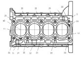
图7是本发明的气缸体顶面视图。Fig. 7 is a top view of the cylinder block of the present invention.
图8是本发明的气缸盖的底面视图。Fig. 8 is a bottom view of the cylinder head of the present invention.
图9是本发明的冷却水套装配后于进气侧的等轴视图。Fig. 9 is an isometric view of the cooling water jacket of the present invention assembled on the intake side.
具体实施方式Detailed ways
下面结合具体实施例和附图来详细说明本发明。The present invention will be described in detail below in conjunction with specific embodiments and accompanying drawings.
如图1、2、3、6,本发明的发动机冷却水套包括气缸体水套1和气缸盖水套2,气缸体水套1由两处挡板13和14隔开而形成第一流道11和第二流道12,第一流道11连接进水口13并且流经排气侧,第二流道12连接出水口14并且流经进气侧,第一流道11通过气缸垫3上的过水孔312与气缸盖水套2连通,第二流道12均通过气缸垫3上的过水孔311与气缸盖水套2连通。出口15是气缸体水套1通往其他冷却系统的出口,出口21是气缸盖水套2通往其他冷却系统的出口。第一流道11主要流经排气侧,第二流道12主要流经进气侧,冷却液主要从进水口13流入第一流道11,然后经过气缸垫3上的过水孔312进入气缸盖水套2,然后再经过气缸垫3上的过水孔311进入第二流道12,最后途径第二流道12从出水口14流出。As shown in Figures 1, 2, 3 and 6, the engine cooling water jacket of the present invention includes a cylinder
如图4、7、8,从图中可以清楚的看到,由于缸孔间与缸盖螺栓孔23的布置位置限制,致使两缸之间水套的厚度比其他区域大,为了均匀流速,需要保证气缸体水套1任意处的纵向通流截面相等,可以在该区域减小高度。因此,气缸体水套1的底部呈波浪状。同时,气缸体水套1的最高高度小于气缸孔的直径。本发明的气缸体水套1和气缸盖水套2均应采用薄水套,而且气缸体水套1的最高高度小于气缸孔40的直径。由于常规水套的设计时,水套的最低端应该低于活塞环第一道气环在下止点时所在位置,而且针对目前车用汽油发动机的冲程缸径比,经验值一般设置为1:1,再加之活塞火力岸高度,常规的水套高度应该约等于1.1乘以气缸孔直径+火力岸高度,本发明采用短水套设计,短水套的高度量化值定义约为一倍气缸孔直径,这样便可以使整个发动机水套的容积减小,从而提高冷却液的流速,利用对流换热,便可以提高冷却效率,降低油耗;同时由于本发明的水套容积小,可以使发动机能更快速暖机,降低暖机过程的油耗和排放。As shown in Figures 4, 7, and 8, it can be clearly seen from the figures that due to the limitation of the layout position between the cylinder bores and the bolt holes 23 of the cylinder head, the thickness of the water jacket between the two cylinders is larger than that of other areas. In order to uniform the flow rate, It is necessary to ensure that the longitudinal flow sections of the cylinder
如图5,挡板13上设有过水孔131连通第一流道11和第二流道12。为了保证挡板13或14附近区域水套中的冷却液的流速均匀,挡板13和14上还设有过水孔,以确保整个水套中的冷却液流速更均匀。As shown in FIG. 5 , a
如图6,气缸垫3上的过水孔31由不同直径的通孔组成。优选的实现方式是将气缸垫3上的过水孔31分成不同直径的两组311和312,通过调整两组过水孔311和312的直径来控制各个区域的流速,以使整个发动机冷却水套中的流速更均匀。气缸垫3的过水孔311和312均匀地布置在气缸孔40周围,这样就可以使冷却液更均匀流过高温区域,提高冷却水套散热性能。第一流道11与气缸盖水套2连通的过水孔311组成的通流面积大于第二流道2与气缸盖水套2连通的过水孔312组成的通流面积。由于第一流道11是连接水泵的,其冷却液压力较高,流速较快,所以第一流11道与气缸盖水套2连通的过水孔311组成的通流面积应该较大,以平衡流速。As shown in Figure 6, the water hole 31 on the
如图7,图中清楚的显示了本发明的冷却水套的第一流道11和第二流道12的以及挡板13和14的位置,以及气缸盖螺栓孔23的位置。孔40为气缸孔。As shown in FIG. 7 , the figure clearly shows the positions of the
如图8,气缸盖水套2通过孔241与气缸垫过水孔312连通,通过孔242与气缸垫过水孔311连通。孔25为燃烧室。As shown in FIG. 8 , the cylinder
如图9,本发明的冷却水套装配后,第一流道11的进水接冷却水泵,第二流道12的出水口接调温器。 As shown in Fig. 9, after the cooling water jacket of the present invention is assembled, the water inlet of the
Claims (8)
Priority Applications (1)
| Application Number | Priority Date | Filing Date | Title |
|---|---|---|---|
| CN201010603738.9A CN102042116A (en) | 2010-12-24 | 2010-12-24 | Engine cooling water jacket |
Applications Claiming Priority (1)
| Application Number | Priority Date | Filing Date | Title |
|---|---|---|---|
| CN201010603738.9A CN102042116A (en) | 2010-12-24 | 2010-12-24 | Engine cooling water jacket |
Publications (1)
| Publication Number | Publication Date |
|---|---|
| CN102042116A true CN102042116A (en) | 2011-05-04 |
Family
ID=43908574
Family Applications (1)
| Application Number | Title | Priority Date | Filing Date |
|---|---|---|---|
| CN201010603738.9A Pending CN102042116A (en) | 2010-12-24 | 2010-12-24 | Engine cooling water jacket |
Country Status (1)
| Country | Link |
|---|---|
| CN (1) | CN102042116A (en) |
Cited By (26)
| Publication number | Priority date | Publication date | Assignee | Title |
|---|---|---|---|---|
| CN102352799A (en) * | 2011-11-08 | 2012-02-15 | 安徽江淮汽车股份有限公司 | Engine cylinder body with open-type water jacket |
| CN102678368A (en) * | 2012-05-28 | 2012-09-19 | 长城汽车股份有限公司 | Engine |
| CN103590885A (en) * | 2013-11-27 | 2014-02-19 | 安徽江淮汽车股份有限公司 | Cooling circulation system of novel structure |
| CN103670768A (en) * | 2012-09-07 | 2014-03-26 | 北京汽车动力总成有限公司 | Engine cooling water jacket and engine cooling system |
| CN104295392A (en) * | 2014-09-22 | 2015-01-21 | 广西玉柴机器股份有限公司 | Engine cooling water jacket |
| CN104454214A (en) * | 2014-11-28 | 2015-03-25 | 长城汽车股份有限公司 | Engine cooling system and vehicle |
| CN104641092A (en) * | 2013-02-21 | 2015-05-20 | 马自达汽车株式会社 | Cooling device for multi-cylinder engines |
| CN104775928A (en) * | 2015-04-27 | 2015-07-15 | 奇瑞汽车股份有限公司 | Water jacket structure for cylinder block and engine cylinder block |
| CN104832311A (en) * | 2015-03-17 | 2015-08-12 | 重庆长安汽车股份有限公司 | Engine cooling water jacket |
| CN105134360A (en) * | 2015-10-16 | 2015-12-09 | 安徽江淮汽车股份有限公司 | Multi-circulation engine cooling system |
| CN106246395A (en) * | 2016-08-01 | 2016-12-21 | 周家全 | A kind of cylinder block cooling system and process thereof |
| CN106246318A (en) * | 2016-08-31 | 2016-12-21 | 奇瑞商用车(安徽)有限公司 | A kind of cooling structure for engine |
| CN106907269A (en) * | 2017-04-26 | 2017-06-30 | 四川森洁燃气设备有限公司 | A kind of durable modified cylinder seal part |
| CN106968827A (en) * | 2017-04-14 | 2017-07-21 | 四川森洁燃气设备有限公司 | A kind of practical sealing cylinder component |
| CN107044356A (en) * | 2016-12-30 | 2017-08-15 | 广西玉柴机器股份有限公司 | The jacket structure for water of the valve diesel of four cylinder two |
| CN108131212A (en) * | 2017-12-29 | 2018-06-08 | 浙江吉利罗佑发动机有限公司 | Engine cool nested structure |
| CN108757139A (en) * | 2018-06-21 | 2018-11-06 | 浙江吉利控股集团有限公司 | A kind of engine cooling method and engine, vehicle |
| CN109057983A (en) * | 2018-09-26 | 2018-12-21 | 潍柴动力股份有限公司 | Engine and its body |
| CN109715926A (en) * | 2016-09-20 | 2019-05-03 | 康明斯公司 | System and method for avoiding structural failure due to high thermal cycling using a cylinder head cooling device |
| CN110159446A (en) * | 2019-07-01 | 2019-08-23 | 广西玉柴机器股份有限公司 | A kind of body cooling water jacket structure of multicylinder engine |
| CN111828156A (en) * | 2019-04-16 | 2020-10-27 | 标致雪铁龙汽车股份有限公司 | A system and method for cooling an engine, and a vehicle |
| CN111852682A (en) * | 2020-06-04 | 2020-10-30 | 浙江义利汽车零部件有限公司 | An engine cooling water jacket system, an engine cooling method and a vehicle |
| CN112377321A (en) * | 2020-11-10 | 2021-02-19 | 隆鑫通用动力股份有限公司 | Water-cooled engine |
| CN114542317A (en) * | 2022-03-17 | 2022-05-27 | 奇瑞汽车股份有限公司 | Cylinder block and engine |
| CN114893283A (en) * | 2022-06-07 | 2022-08-12 | 哈尔滨东安汽车动力股份有限公司 | Supercharged engine cooling system |
| CN118327805A (en) * | 2024-04-25 | 2024-07-12 | 中国第一汽车股份有限公司 | Cooling jackets, engines and vehicles |
Citations (5)
| Publication number | Priority date | Publication date | Assignee | Title |
|---|---|---|---|---|
| CN2751151Y (en) * | 2004-12-03 | 2006-01-11 | 长安汽车(集团)有限责任公司 | A Crankcase Water Jacket with Improved Structure |
| US7086356B2 (en) * | 2003-07-24 | 2006-08-08 | Honda Motor Co., Ltd. | Engine cooling structure |
| US20090007858A1 (en) * | 2007-07-06 | 2009-01-08 | Brp-Rotax Gmbh & Co. Kg | Internal combustion engine cooling system |
| CN201288614Y (en) * | 2008-11-19 | 2009-08-12 | 三阳工业股份有限公司 | Cooling water channel structure for engine |
| CN101655046A (en) * | 2009-09-08 | 2010-02-24 | 奇瑞汽车股份有限公司 | Cooling water jacket structure of engine and engine cooling method |
-
2010
- 2010-12-24 CN CN201010603738.9A patent/CN102042116A/en active Pending
Patent Citations (5)
| Publication number | Priority date | Publication date | Assignee | Title |
|---|---|---|---|---|
| US7086356B2 (en) * | 2003-07-24 | 2006-08-08 | Honda Motor Co., Ltd. | Engine cooling structure |
| CN2751151Y (en) * | 2004-12-03 | 2006-01-11 | 长安汽车(集团)有限责任公司 | A Crankcase Water Jacket with Improved Structure |
| US20090007858A1 (en) * | 2007-07-06 | 2009-01-08 | Brp-Rotax Gmbh & Co. Kg | Internal combustion engine cooling system |
| CN201288614Y (en) * | 2008-11-19 | 2009-08-12 | 三阳工业股份有限公司 | Cooling water channel structure for engine |
| CN101655046A (en) * | 2009-09-08 | 2010-02-24 | 奇瑞汽车股份有限公司 | Cooling water jacket structure of engine and engine cooling method |
Cited By (35)
| Publication number | Priority date | Publication date | Assignee | Title |
|---|---|---|---|---|
| CN102352799A (en) * | 2011-11-08 | 2012-02-15 | 安徽江淮汽车股份有限公司 | Engine cylinder body with open-type water jacket |
| CN102678368B (en) * | 2012-05-28 | 2015-09-23 | 长城汽车股份有限公司 | Motor |
| CN102678368A (en) * | 2012-05-28 | 2012-09-19 | 长城汽车股份有限公司 | Engine |
| CN103670768A (en) * | 2012-09-07 | 2014-03-26 | 北京汽车动力总成有限公司 | Engine cooling water jacket and engine cooling system |
| CN104641092A (en) * | 2013-02-21 | 2015-05-20 | 马自达汽车株式会社 | Cooling device for multi-cylinder engines |
| CN104641092B (en) * | 2013-02-21 | 2017-03-29 | 马自达汽车株式会社 | Cooling device for multi-cylinder engines |
| CN103590885A (en) * | 2013-11-27 | 2014-02-19 | 安徽江淮汽车股份有限公司 | Cooling circulation system of novel structure |
| CN104295392A (en) * | 2014-09-22 | 2015-01-21 | 广西玉柴机器股份有限公司 | Engine cooling water jacket |
| CN104454214A (en) * | 2014-11-28 | 2015-03-25 | 长城汽车股份有限公司 | Engine cooling system and vehicle |
| CN104832311A (en) * | 2015-03-17 | 2015-08-12 | 重庆长安汽车股份有限公司 | Engine cooling water jacket |
| CN104832311B (en) * | 2015-03-17 | 2018-09-11 | 重庆长安汽车股份有限公司 | engine cooling water jacket |
| CN104775928A (en) * | 2015-04-27 | 2015-07-15 | 奇瑞汽车股份有限公司 | Water jacket structure for cylinder block and engine cylinder block |
| CN105134360A (en) * | 2015-10-16 | 2015-12-09 | 安徽江淮汽车股份有限公司 | Multi-circulation engine cooling system |
| CN106246395A (en) * | 2016-08-01 | 2016-12-21 | 周家全 | A kind of cylinder block cooling system and process thereof |
| CN106246318A (en) * | 2016-08-31 | 2016-12-21 | 奇瑞商用车(安徽)有限公司 | A kind of cooling structure for engine |
| CN109715926A (en) * | 2016-09-20 | 2019-05-03 | 康明斯公司 | System and method for avoiding structural failure due to high thermal cycling using a cylinder head cooling device |
| CN107044356A (en) * | 2016-12-30 | 2017-08-15 | 广西玉柴机器股份有限公司 | The jacket structure for water of the valve diesel of four cylinder two |
| CN106968827A (en) * | 2017-04-14 | 2017-07-21 | 四川森洁燃气设备有限公司 | A kind of practical sealing cylinder component |
| CN106907269B (en) * | 2017-04-26 | 2019-03-19 | 四川森洁燃气设备有限公司 | A kind of durable modified cylinder seal part |
| CN106907269A (en) * | 2017-04-26 | 2017-06-30 | 四川森洁燃气设备有限公司 | A kind of durable modified cylinder seal part |
| CN108131212B (en) * | 2017-12-29 | 2020-06-23 | 浙江吉利动力总成有限公司 | Engine cooling jacket structure |
| CN108131212A (en) * | 2017-12-29 | 2018-06-08 | 浙江吉利罗佑发动机有限公司 | Engine cool nested structure |
| CN108757139A (en) * | 2018-06-21 | 2018-11-06 | 浙江吉利控股集团有限公司 | A kind of engine cooling method and engine, vehicle |
| CN108757139B (en) * | 2018-06-21 | 2019-12-20 | 浙江吉利控股集团有限公司 | Engine cooling method, engine and vehicle |
| CN109057983A (en) * | 2018-09-26 | 2018-12-21 | 潍柴动力股份有限公司 | Engine and its body |
| CN111828156A (en) * | 2019-04-16 | 2020-10-27 | 标致雪铁龙汽车股份有限公司 | A system and method for cooling an engine, and a vehicle |
| CN110159446B (en) * | 2019-07-01 | 2024-03-12 | 广西玉柴机器股份有限公司 | Engine body cooling water jacket structure of multi-cylinder engine |
| CN110159446A (en) * | 2019-07-01 | 2019-08-23 | 广西玉柴机器股份有限公司 | A kind of body cooling water jacket structure of multicylinder engine |
| CN111852682A (en) * | 2020-06-04 | 2020-10-30 | 浙江义利汽车零部件有限公司 | An engine cooling water jacket system, an engine cooling method and a vehicle |
| CN111852682B (en) * | 2020-06-04 | 2022-04-05 | 浙江义利汽车零部件有限公司 | An engine cooling water jacket system, an engine cooling method and a vehicle |
| CN112377321B (en) * | 2020-11-10 | 2022-01-25 | 隆鑫通用动力股份有限公司 | Water-cooled engine |
| CN112377321A (en) * | 2020-11-10 | 2021-02-19 | 隆鑫通用动力股份有限公司 | Water-cooled engine |
| CN114542317A (en) * | 2022-03-17 | 2022-05-27 | 奇瑞汽车股份有限公司 | Cylinder block and engine |
| CN114893283A (en) * | 2022-06-07 | 2022-08-12 | 哈尔滨东安汽车动力股份有限公司 | Supercharged engine cooling system |
| CN118327805A (en) * | 2024-04-25 | 2024-07-12 | 中国第一汽车股份有限公司 | Cooling jackets, engines and vehicles |
Similar Documents
| Publication | Publication Date | Title |
|---|---|---|
| CN102042116A (en) | Engine cooling water jacket | |
| CN110594033A (en) | Engine cooling water jacket structure | |
| JP2009062836A (en) | Cylinder head of internal combustion engine | |
| CN215761905U (en) | Supercharged engine cooling system | |
| CN114233507B (en) | Cooling water jacket of engine cylinder cover | |
| CN107956590B (en) | Engine cooling system and cooling method thereof | |
| CN210068326U (en) | Engine cooling water jacket | |
| CN107905882A (en) | Reverse-flow cooling system of engine | |
| JP2020522646A (en) | V type 12 cylinder diesel engine | |
| CN111810311B (en) | Engine cooling water jacket structure and engine | |
| CN111878247B (en) | Engine cooling system and automobile | |
| CN108131212B (en) | Engine cooling jacket structure | |
| CN203640848U (en) | Bypass engine cooling water jacket | |
| CN110344961B (en) | Cooling water jacket, control method thereof and engine structure | |
| JP2011220292A (en) | Cooling device of internal combustion engine | |
| CN115306512B (en) | A rapid warm-up equalization cooling system for multi-cylinder V-type diesel engines | |
| CN205243618U (en) | Automobile engine | |
| CN216077303U (en) | Cooling water jacket of automobile engine | |
| CN204003135U (en) | A kind of multi-cylinder gasoline engine Cooling of Cylinder Head jacket structure for water | |
| CN115523047A (en) | Engine assembly | |
| CN210106004U (en) | Engine cooling water jacket structure and engine | |
| CN115539236A (en) | Engine assembly and warm-up system | |
| CN224161780U (en) | Engines and vehicles | |
| CN216111031U (en) | Cooling water jacket of cylinder head, engine and vehicle | |
| CN114592986B (en) | Engine for vehicle and vehicle |
Legal Events
| Date | Code | Title | Description |
|---|---|---|---|
| C06 | Publication | ||
| PB01 | Publication | ||
| C10 | Entry into substantive examination | ||
| SE01 | Entry into force of request for substantive examination | ||
| CI01 | Publication of corrected invention patent application |
Correction item: Application Date Correct: 20110215 False: 20101224 Number: 18 Volume: 27 |
|
| CI02 | Correction of invention patent application |
Correction item: Application Date Correct: 20110215 False: 20101224 Number: 18 Page: The title page Volume: 27 |
|
| ERR | Gazette correction |
Free format text: CORRECT: APPLICATION DATE; FROM: 2010.12.24 TO: 2011.02.15 |
|
| C12 | Rejection of a patent application after its publication | ||
| RJ01 | Rejection of invention patent application after publication |
Application publication date: 20110504 |