CN102007031B - Vehicle travel control system - Google Patents
Vehicle travel control system Download PDFInfo
- Publication number
- CN102007031B CN102007031B CN2009801132363A CN200980113236A CN102007031B CN 102007031 B CN102007031 B CN 102007031B CN 2009801132363 A CN2009801132363 A CN 2009801132363A CN 200980113236 A CN200980113236 A CN 200980113236A CN 102007031 B CN102007031 B CN 102007031B
- Authority
- CN
- China
- Prior art keywords
- plan
- vehicle
- travelling
- section
- deceleration
- Prior art date
- Legal status (The legal status is an assumption and is not a legal conclusion. Google has not performed a legal analysis and makes no representation as to the accuracy of the status listed.)
- Expired - Fee Related
Links
Images


Classifications
-
- B—PERFORMING OPERATIONS; TRANSPORTING
- B60—VEHICLES IN GENERAL
- B60W—CONJOINT CONTROL OF VEHICLE SUB-UNITS OF DIFFERENT TYPE OR DIFFERENT FUNCTION; CONTROL SYSTEMS SPECIALLY ADAPTED FOR HYBRID VEHICLES; ROAD VEHICLE DRIVE CONTROL SYSTEMS FOR PURPOSES NOT RELATED TO THE CONTROL OF A PARTICULAR SUB-UNIT
- B60W20/00—Control systems specially adapted for hybrid vehicles
- B60W20/10—Controlling the power contribution of each of the prime movers to meet required power demand
- B60W20/12—Controlling the power contribution of each of the prime movers to meet required power demand using control strategies taking into account route information
-
- B—PERFORMING OPERATIONS; TRANSPORTING
- B60—VEHICLES IN GENERAL
- B60W—CONJOINT CONTROL OF VEHICLE SUB-UNITS OF DIFFERENT TYPE OR DIFFERENT FUNCTION; CONTROL SYSTEMS SPECIALLY ADAPTED FOR HYBRID VEHICLES; ROAD VEHICLE DRIVE CONTROL SYSTEMS FOR PURPOSES NOT RELATED TO THE CONTROL OF A PARTICULAR SUB-UNIT
- B60W10/00—Conjoint control of vehicle sub-units of different type or different function
- B60W10/04—Conjoint control of vehicle sub-units of different type or different function including control of propulsion units
- B60W10/06—Conjoint control of vehicle sub-units of different type or different function including control of propulsion units including control of combustion engines
-
- B—PERFORMING OPERATIONS; TRANSPORTING
- B60—VEHICLES IN GENERAL
- B60W—CONJOINT CONTROL OF VEHICLE SUB-UNITS OF DIFFERENT TYPE OR DIFFERENT FUNCTION; CONTROL SYSTEMS SPECIALLY ADAPTED FOR HYBRID VEHICLES; ROAD VEHICLE DRIVE CONTROL SYSTEMS FOR PURPOSES NOT RELATED TO THE CONTROL OF A PARTICULAR SUB-UNIT
- B60W10/00—Conjoint control of vehicle sub-units of different type or different function
- B60W10/04—Conjoint control of vehicle sub-units of different type or different function including control of propulsion units
- B60W10/08—Conjoint control of vehicle sub-units of different type or different function including control of propulsion units including control of electric propulsion units, e.g. motors or generators
-
- B—PERFORMING OPERATIONS; TRANSPORTING
- B60—VEHICLES IN GENERAL
- B60W—CONJOINT CONTROL OF VEHICLE SUB-UNITS OF DIFFERENT TYPE OR DIFFERENT FUNCTION; CONTROL SYSTEMS SPECIALLY ADAPTED FOR HYBRID VEHICLES; ROAD VEHICLE DRIVE CONTROL SYSTEMS FOR PURPOSES NOT RELATED TO THE CONTROL OF A PARTICULAR SUB-UNIT
- B60W20/00—Control systems specially adapted for hybrid vehicles
-
- G—PHYSICS
- G08—SIGNALLING
- G08G—TRAFFIC CONTROL SYSTEMS
- G08G1/00—Traffic control systems for road vehicles
- G08G1/09—Arrangements for giving variable traffic instructions
- G08G1/0962—Arrangements for giving variable traffic instructions having an indicator mounted inside the vehicle, e.g. giving voice messages
- G08G1/0968—Systems involving transmission of navigation instructions to the vehicle
- G08G1/096805—Systems involving transmission of navigation instructions to the vehicle where the transmitted instructions are used to compute a route
- G08G1/096827—Systems involving transmission of navigation instructions to the vehicle where the transmitted instructions are used to compute a route where the route is computed onboard
-
- B—PERFORMING OPERATIONS; TRANSPORTING
- B60—VEHICLES IN GENERAL
- B60W—CONJOINT CONTROL OF VEHICLE SUB-UNITS OF DIFFERENT TYPE OR DIFFERENT FUNCTION; CONTROL SYSTEMS SPECIALLY ADAPTED FOR HYBRID VEHICLES; ROAD VEHICLE DRIVE CONTROL SYSTEMS FOR PURPOSES NOT RELATED TO THE CONTROL OF A PARTICULAR SUB-UNIT
- B60W2552/00—Input parameters relating to infrastructure
- B60W2552/20—Road profile, i.e. the change in elevation or curvature of a plurality of continuous road segments
-
- B—PERFORMING OPERATIONS; TRANSPORTING
- B60—VEHICLES IN GENERAL
- B60W—CONJOINT CONTROL OF VEHICLE SUB-UNITS OF DIFFERENT TYPE OR DIFFERENT FUNCTION; CONTROL SYSTEMS SPECIALLY ADAPTED FOR HYBRID VEHICLES; ROAD VEHICLE DRIVE CONTROL SYSTEMS FOR PURPOSES NOT RELATED TO THE CONTROL OF A PARTICULAR SUB-UNIT
- B60W2556/00—Input parameters relating to data
- B60W2556/45—External transmission of data to or from the vehicle
- B60W2556/50—External transmission of data to or from the vehicle of positioning data, e.g. GPS [Global Positioning System] data
-
- Y—GENERAL TAGGING OF NEW TECHNOLOGICAL DEVELOPMENTS; GENERAL TAGGING OF CROSS-SECTIONAL TECHNOLOGIES SPANNING OVER SEVERAL SECTIONS OF THE IPC; TECHNICAL SUBJECTS COVERED BY FORMER USPC CROSS-REFERENCE ART COLLECTIONS [XRACs] AND DIGESTS
- Y02—TECHNOLOGIES OR APPLICATIONS FOR MITIGATION OR ADAPTATION AGAINST CLIMATE CHANGE
- Y02T—CLIMATE CHANGE MITIGATION TECHNOLOGIES RELATED TO TRANSPORTATION
- Y02T10/00—Road transport of goods or passengers
- Y02T10/60—Other road transportation technologies with climate change mitigation effect
- Y02T10/62—Hybrid vehicles
Landscapes
- Engineering & Computer Science (AREA)
- Chemical & Material Sciences (AREA)
- Combustion & Propulsion (AREA)
- Mechanical Engineering (AREA)
- Transportation (AREA)
- Physics & Mathematics (AREA)
- General Physics & Mathematics (AREA)
- Remote Sensing (AREA)
- Radar, Positioning & Navigation (AREA)
- Automation & Control Theory (AREA)
- Hybrid Electric Vehicles (AREA)
- Control Of Vehicle Engines Or Engines For Specific Uses (AREA)
- Electric Propulsion And Braking For Vehicles (AREA)
- Controls For Constant Speed Travelling (AREA)
Abstract
Description
技术领域 technical field
本发明涉及一种基于行驶计划控制车辆的行驶的车辆行驶控制系统。The present invention relates to a vehicle travel control system that controls travel of a vehicle based on a travel plan.
背景技术 Background technique
在日本专利申请公开No.2007-187090(JP-A-2007-187090)中公开了以低的燃料消耗实现车辆的行驶的技术。车辆行驶控制系统安装在内燃机和电动机是驱动源的混合动力车辆中。该系统实现了将车辆的行驶速度保持在目标巡航速度的速度保持控制。车辆行驶控制系统设定高于目标巡航速度的上限速度和低于目标巡航速度的下限速度。该系统以内燃机作为驱动源将车辆加速到上限速度,当速度达到上限速度时车辆在内燃机停止的情况下行驶,并且当速度达到下限速度时启动内燃机以使车辆加速。A technique of realizing running of a vehicle with low fuel consumption is disclosed in Japanese Patent Application Publication No. 2007-187090 (JP-A-2007-187090). The vehicle travel control system is installed in a hybrid vehicle in which an internal combustion engine and an electric motor are driving sources. This system realizes the speed maintaining control that keeps the running speed of the vehicle at the target cruising speed. The vehicle travel control system sets an upper limit speed higher than the target cruising speed and a lower limit speed lower than the target cruising speed. This system accelerates the vehicle up to an upper limit speed with the internal combustion engine as a drive source, runs with the internal combustion engine stopped when the speed reaches the upper limit speed, and starts the internal combustion engine to accelerate the vehicle when the speed reaches the lower limit speed.
然而,存在如下情况,当车辆正在行驶时出现内燃机的非停止状态,诸如内燃机、电池和暖气机的预热。在这样的情况下,车辆行驶控制系统可能不能实现如所计划的低燃料消耗的行驶,并且燃料效率恶化。However, there are cases where a non-stop state of the internal combustion engine occurs while the vehicle is running, such as warm-up of the internal combustion engine, battery, and heater. In such a case, the vehicle travel control system may not realize travel with low fuel consumption as planned, and fuel efficiency may deteriorate.
发明内容 Contents of the invention
本发明提供了一种车辆行驶控制系统,即使当在基于通过停止内燃机以使车辆减速的行驶计划来控制车辆的行驶的情况下出现内燃机的非停止状态时,该车辆行驶控制系统仍可以防止燃料效率恶化。The present invention provides a vehicle travel control system capable of preventing fuel Efficiency deteriorates.
根据本发明的第一方面的车辆行驶控制系统涉及一种基于行驶计划来控制车辆的行驶的车辆行驶控制系统。该车辆行驶控制系统具有:初始行驶计划产生部,该初始行驶计划产生部产生初始行驶计划,该初始行驶计划包括停止车辆的内燃机以使车辆减速的减速区间;以及第一重新计划部,该第一重新计划部当在车辆正在行驶时出现内燃机的非停止状态时重新计划初始行驶计划,使得减速区间中的目标减速度被设定为大于初始行驶计划中的目标减速度。A vehicle travel control system according to a first aspect of the present invention relates to a vehicle travel control system that controls travel of a vehicle based on a travel plan. The vehicle travel control system has: an initial travel plan generating unit that generates an initial travel plan including a deceleration section in which an internal combustion engine of the vehicle is stopped to decelerate the vehicle; and a first replanning unit that generates the initial travel plan. A replanning section replans the initial travel plan when the non-stop state of the internal combustion engine occurs while the vehicle is running, so that the target deceleration in the deceleration section is set larger than the target deceleration in the initial travel plan.
根据该车辆行驶控制系统,初始行驶计划产生部产生初始行驶计划,该初始行驶计划包括停止内燃机以使车辆减速的减速区间。这允许改进燃料效率。当在车辆正在行驶时出现内燃机的非停止状态时,第一重新计划部重新计划初始行驶计划,使得减速区间中的目标减速度被设定为大于初始行驶计划中的目标减速度。因此,改进了减速区间中的平均速度,由此缩短了减速所需的时间。这允许防止由于长时间段的连续减速而引起内燃机的热效率的下降。此外,在行驶计划中的行驶时间或平均速度是固定的情况下,可以将作为减速区间中的时间减少的结果而提供的剩余时间分配给其他区间。因此,对于整体行驶计划可以实现低的燃料消耗。如上文所述,即使当在基于通过停止内燃机以使车辆减速的行驶计划来控制车辆的行驶的情况下出现内燃机的非停止状态时,本发明的第一方面仍允许防止燃料效率恶化。According to this vehicle travel control system, the initial travel plan generating unit generates an initial travel plan including a deceleration section in which the internal combustion engine is stopped to decelerate the vehicle. This allows for improved fuel efficiency. When the non-stop state of the internal combustion engine occurs while the vehicle is running, the first replanning section replans the initial travel plan such that the target deceleration in the deceleration section is set larger than the target deceleration in the initial travel plan. Therefore, the average speed in the deceleration section is improved, thereby shortening the time required for deceleration. This allows preventing a decrease in thermal efficiency of the internal combustion engine due to continuous deceleration for a long period of time. Furthermore, in the case where the travel time or the average speed in the travel plan is fixed, the remaining time provided as a result of the time reduction in the deceleration section may be allocated to other sections. Therefore, low fuel consumption can be achieved for the overall driving plan. As described above, the first aspect of the present invention allows prevention of fuel efficiency deterioration even when the non-stop state of the internal combustion engine occurs in the case where the travel of the vehicle is controlled based on a travel plan to decelerate the vehicle by stopping the internal combustion engine.
当在车辆正在行驶时出现内燃机的非停止状态时,第一重新计划部可以重新计划初始行驶计划,使得继减速区间之后的加速区间中的目标加速度被设定为大于初始行驶计划中的目标加速度。当出现内燃机的非停止状态时,第一重新计划部重新计划初始行驶计划,使得继减速区间之后的加速区间中的目标加速度被设定为更大。因此,增加了加速区间中的平均速度,由此减少了加速区间中的行驶时间。因此,在行驶计划中的行驶时间或平均速度是固定的情况下,可以将作为减速区间中的时间减少的结果而提供的剩余时间分配给其他区间。因此,对于整体行驶计划可以实现低的燃料消耗。When the non-stop state of the internal combustion engine occurs while the vehicle is running, the first replanning section may replan the initial travel plan so that the target acceleration in the acceleration section following the deceleration section is set to be greater than the target acceleration in the initial travel plan . When the non-stop state of the internal combustion engine occurs, the first replanning section replans the initial travel plan such that the target acceleration in the acceleration section subsequent to the deceleration section is set to be larger. Therefore, the average speed in the acceleration section is increased, thereby reducing the travel time in the acceleration section. Therefore, in the case where the travel time or the average speed in the travel plan is fixed, the remaining time provided as a result of the time reduction in the deceleration section can be allocated to other sections. Therefore, low fuel consumption can be achieved for the overall driving plan.
车辆的驱动方式是混合动力方式,其中车辆由内燃机和以电池作为电源的电动机来驱动。第一重新计划部可以利用减速区间中的新的目标减速度来重新计划初始行驶计划,该新的目标减速度是将减速度产生最大再生的最大再生制动减速度和内燃机的理想热效率的乘积除以当前时间内燃机的热效率和电池充放电效率而得到的值。The driving method of the vehicle is a hybrid method in which the vehicle is driven by an internal combustion engine and an electric motor powered by a battery. The first re-planning unit may re-plan the initial travel plan using a new target deceleration in the deceleration section, the new target deceleration being the product of the maximum regenerative braking deceleration that maximizes regeneration of the deceleration and the ideal thermal efficiency of the internal combustion engine The value obtained by dividing the thermal efficiency of the combustion engine and the battery charge and discharge efficiency at the current time.
将最大再生制动减速度和内燃机的理想热效率的乘积除以当前时间热效率和电池充放电效率而得到的值被设定为内燃机进入非停止状态的减速区间中的目标减速度。因此,增加了减速区间中的减速度。换言之,与减速度相对应的内燃机的热效率的减小的量被转换为大的制动力,并且因此改进了减速区间中的平均速度。因此,可以减少减速区间中的行驶时间。这允许进一步防止燃料效率恶化。A value obtained by dividing the product of the maximum regenerative braking deceleration and the ideal thermal efficiency of the internal combustion engine by the current time thermal efficiency and battery charge-discharge efficiency is set as the target deceleration in the deceleration section in which the internal combustion engine enters the non-stop state. Therefore, the deceleration in the deceleration section is increased. In other words, the amount of reduction in the thermal efficiency of the internal combustion engine corresponding to the deceleration is converted into a large braking force, and thus the average speed in the deceleration section is improved. Therefore, the travel time in the deceleration section can be reduced. This allows further prevention of fuel efficiency deterioration.
第一重新计划部可以利用新的目标减速度来重新计划初始行驶计划,该新的目标减速度是将与电池的输出限制相对应的加速度与加速区间中的目标加速度相加而得到的值。当如上文所述减速区间中的减速度被设定为更大的时候,反馈到电池的再生量增加。因此,可以容易地将电池充满电。因此,将与电池的输出限制相对应的加速度与初始行驶计划产生部产生的目标加速度相加而得到的值被设定为继内燃机进入非停止状态的减速区间之后的加速区间中的目标加速度。这允许防止由于电池充满电而不能进行再生的情况。因此,有效地实现了对电池的再生电力的反馈,由此允许进一步改进燃料效率。The first re-planning unit may re-plan the initial travel plan using a new target deceleration that is a value obtained by adding an acceleration corresponding to an output limit of the battery to a target acceleration in the acceleration section. When the deceleration in the deceleration section is set to be larger as described above, the amount of regeneration fed back to the battery increases. Therefore, the battery can be fully charged easily. Therefore, a value obtained by adding the acceleration corresponding to the output limit of the battery to the target acceleration generated by the initial travel plan generator is set as the target acceleration in the acceleration section following the deceleration section in which the internal combustion engine enters the non-stop state. This allows preventing a situation where regeneration is not possible because the battery is fully charged. Therefore, feedback to the regenerative electric power of the battery is effectively realized, thereby allowing further improvement of fuel efficiency.
初始行驶计划产生部可以估计内燃机进入非停止状态的所估计的非停止区间,并且通过使用用于内燃机处于非停止状态情况下的热效率优选评估等式来产生初始行驶计划。车辆行驶控制系统基于内燃机进入非停止状态的所估计的非停止区间的估计来产生初始行驶计划。因此,初始行驶计划可以是将初始行驶计划作为整体进行优化的通常最优的计划。The initial travel plan generating section may estimate an estimated non-stop section where the internal combustion engine enters the non-stop state, and generate the initial travel plan by using a thermal efficiency optimal evaluation equation for a case where the internal combustion engine is in the non-stop state. A vehicle travel control system generates an initial travel plan based on an estimate of an estimated non-stop interval in which the internal combustion engine enters a non-stop state. Therefore, the initial travel plan may be a generally optimal plan optimizing the initial travel plan as a whole.
根据该方面的车辆行驶控制系统可以包括:临时行驶时间计算部,该临时行驶时间计算部将指定时间与初始行驶计划的每个区间的行驶时间相加来计算临时行驶时间;临时行驶计划产生部,该临时行驶计划产生部通过将临时行驶时间作为约束条件的优化过程来产生临时行驶计划;临时燃料消耗计算部,该临时燃料消耗计算部计算临时行驶计划中的每个区间的燃料消耗;预期燃料效率改进计算部,该预期燃料效率改进计算部基于临时行驶计划中的每个区间的燃料消耗和初始行驶计划中的每个区间的燃料消耗来计算临时行驶计划相对于初始行驶计划的预期燃料效率改进;剩余行驶时间计算部,该剩余行驶时间计算部从初始行驶计划中的每个区间的行驶时间中减去由第一重新计划部重新计划的行驶计划中的每个区间的行驶时间,以计算每个区间的剩余行驶时间;以及第二重新计划部,该第二重新计划部通过将剩余行驶时间与预期燃料效率改进最大的区间的行驶时间相加而得到的行驶时间作为约束条件的优化过程来重新计划行驶计划。The vehicle travel control system according to this aspect may include: a provisional travel time calculation section that calculates the provisional travel time by adding a designated time to the travel time for each section of the initial travel plan; a provisional travel plan generation section , the provisional travel plan generation unit generates a provisional travel plan through an optimization process that takes the provisional travel time as a constraint condition; the provisional fuel consumption calculation unit calculates the fuel consumption of each interval in the provisional travel plan; the expected a fuel efficiency improvement calculation section that calculates an expected fuel consumption of the provisional travel plan with respect to the initial travel plan based on the fuel consumption of each section in the provisional travel plan and the fuel consumption of each section in the initial travel plan efficiency improvement; a remaining travel time calculation section that subtracts the travel time for each section in the travel plan replanned by the first replanning section from the travel time for each section in the initial travel plan, to calculate the remaining travel time for each section; and a second re-planning section that uses, as a constraint condition, a travel time obtained by adding the remaining travel time to the travel time of the section where the expected improvement in fuel efficiency is the largest Optimization process to re-plan the travel plan.
在车辆行驶控制系统中,计算用于初始行驶计划中的每个区间的临时行驶时间,产生将临时行驶时间作为约束条件的临时行驶计划,计算临时行驶计划中的每个区间的临时燃料消耗,并且计算临时行驶计划相对于初始行驶计划的预期燃料效率改进。当第一重新计划部已重新计划初始行驶计划时,通过将预期燃料效率最大的区间的行驶时间和重新计划的行驶计划中的关注的区间的剩余行驶时间加在一起的行驶时间作为约束条件来执行优化过程以重新产生行驶计划。如上文所述,当在行驶时出现内燃机非停止状态时,第二重新计划部将由第一重新计划部重新配置的区间的剩余行驶时间分配给其他区间并且因此重新产生行驶计划。因此,对于整体行驶计划可以实现低的燃料消耗。此外,可以快速地和容易地重新产生行驶计划。In the vehicle travel control system, calculate the provisional travel time for each section in the initial travel plan, generate a provisional travel plan with the provisional travel time as a constraint, and calculate provisional fuel consumption for each section in the provisional travel plan, And an expected fuel efficiency improvement of the provisional travel plan relative to the initial travel plan is calculated. When the first replanning section has replanned the initial travel plan, by adding together the travel time of the section where the fuel efficiency is expected to be the greatest and the remaining travel time of the section of interest in the replanned travel plan added together as a constraint condition. An optimization process is performed to regenerate the drive plan. As described above, when the internal combustion engine non-stop state occurs while traveling, the second replanning section allocates the remaining travel time of the section reconfigured by the first replanning section to other sections and thus regenerates the travel plan. Therefore, low fuel consumption can be achieved for the overall driving plan. Furthermore, the driving plan can be quickly and easily reproduced.
第二重新计划部可以按照内燃机的非停止状态的原因来重新计划初始行驶计划。车辆行驶控制系统可以按照内燃机的非停止状态的原因来重新计划初始行驶计划并且因此可以适当地减少燃料消耗。The second re-planning unit may re-plan the initial travel plan according to the reason of the non-stop state of the internal combustion engine. The vehicle travel control system can replan the original travel plan according to the reason of the non-stop state of the internal combustion engine and thus can appropriately reduce fuel consumption.
本发明的第二方面涉及一种基于行驶计划的车辆行驶控制系统。该车辆行驶控制系统包括:初始行驶计划产生部,该初始行驶计划产生部估计车辆的燃料消耗并且通过考虑燃料消耗特性来产生初始行驶计划;实际燃料消耗计算部,该实际燃料消耗计算部计算基于初始行驶计划行驶的车辆的实际燃料消耗;以及行驶计划重新配置部,该行驶计划重新配置部当实际燃料消耗超过初始行驶计划的预期燃料消耗时重新配置行驶计划,使得预期燃料消耗变得小于初始行驶计划中的预期燃料消耗。A second aspect of the present invention relates to a vehicle travel control system based on a travel plan. The vehicle travel control system includes: an initial travel plan generation section that estimates fuel consumption of the vehicle and generates an initial travel plan by considering fuel consumption characteristics; an actual fuel consumption calculation section that calculates the vehicle based on actual fuel consumption of the vehicle traveling on the initial travel plan; and a travel plan reconfiguration section that reconfigures the travel plan so that the expected fuel consumption becomes smaller than the initial fuel consumption when the actual fuel consumption exceeds the expected fuel consumption of the initial travel plan Expected fuel consumption in the drive plan.
本发明的第三方面涉及一种用于基于行驶计划来控制车辆的行驶的行驶控制方法。该行驶控制方法包括以下步骤:产生初始行驶计划,该初始行驶计划包括停止车辆的内燃机以使车辆减速的减速区间;以及当在车辆正在行驶时出现内燃机的非停止状态时,重新计划初始行驶计划,使得减速区间中的目标减速度被设定为大于初始行驶计划中的目标减速度。A third aspect of the present invention relates to a travel control method for controlling travel of a vehicle based on a travel plan. The travel control method includes the steps of: generating an initial travel plan including a deceleration section in which an internal combustion engine of the vehicle is stopped to decelerate the vehicle; and when a non-stop state of the internal combustion engine occurs while the vehicle is running, replanning the initial travel plan , so that the target deceleration in the deceleration section is set to be larger than the target deceleration in the initial travel plan.
即使当在基于通过停止内燃机以使车辆减速的行驶计划来控制车辆的行驶的情况下出现内燃机的非停止状态时,本发明仍允许防止燃料效率恶化。Even when a non-stop state of the internal combustion engine occurs while the running of the vehicle is controlled based on a travel plan that decelerates the vehicle by stopping the internal combustion engine, the present invention allows preventing fuel efficiency from deteriorating.
附图说明 Description of drawings
通过下文参照附图对示例性实施例的描述,本发明的前述和进一步的目的、特征和优点将变得显而易见,在附图中相同的附图标记用于表示相同的元素,并且在附图中:The foregoing and further objects, features and advantages of the present invention will become apparent from the following description of exemplary embodiments with reference to the accompanying drawings, in which like reference numerals are used for like elements, and in which middle:
图1是示出根据实施例的车辆行驶控制系统的构造的示图;FIG. 1 is a diagram showing the configuration of a vehicle travel control system according to an embodiment;
图2是用于示范ECU的处理操作的流程图;FIG. 2 is a flowchart for exemplary processing operations of an ECU;
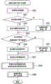
图3是用于示范ECU的行驶计划重新配置过程的操作的流程图;FIG. 3 is a flowchart for demonstrating the operation of a drive plan reconfiguration process of an ECU;
图4A和4B是指示速度和行驶距离之间的关系的曲线图;4A and 4B are graphs indicating the relationship between speed and travel distance;
图5是用于示范ECU的初始行驶计划产生过程的操作的流程图;5 is a flowchart for demonstrating the operation of an initial travel plan generation process of the ECU;
图6是指示评估值和马力之间的关系的曲线图;FIG. 6 is a graph indicating the relationship between evaluation values and horsepower;
图7A和7B是指示速度和行驶距离之间的关系的曲线图;7A and 7B are graphs indicating the relationship between speed and travel distance;
图8是示出根据第三实施例的车辆行驶控制系统的构造的示图;FIG. 8 is a diagram showing the configuration of a vehicle travel control system according to a third embodiment;
图9是用于示范ECU的处理操作的流程图;9 is a flow chart for an exemplary processing operation of an ECU;
图10A和10B是指示速度和行驶距离之间的关系的曲线图;10A and 10B are graphs indicating the relationship between speed and travel distance;
图11是用于示范ECU的处理操作的流程图;以及FIG. 11 is a flow chart for the processing operation of an exemplary ECU; and
图12是指示速度和行驶距离之间的关系的曲线图。FIG. 12 is a graph indicating the relationship between speed and travel distance.
具体实施方式 Detailed ways
下文中将参照附图详细地描述根据本发明的车辆行驶控制系统的实施例。在本实施例中,将描述在能够利用内燃机和电动机作为驱动源进行自动驾驶操作的混合动力类型车辆中安装的车辆行驶控制系统。根据本实施例的车辆行驶控制系统通过利用约束条件和评估功能的优化过程来产生行驶计划并且基于该行驶计划来控制车辆的行驶。在本实施例中,将描述产生由加速度、减速度、恒速行驶等表示的速度模式作为行驶计划的情况。然而,该系统可以产生由其他参数表示的行驶计划。在所有图中相同的附图标记用于表示相同或相应的元素。Hereinafter, embodiments of a vehicle travel control system according to the present invention will be described in detail with reference to the accompanying drawings. In this embodiment, a vehicle travel control system installed in a hybrid type vehicle capable of automatic driving operation using an internal combustion engine and an electric motor as drive sources will be described. The vehicle travel control system according to the present embodiment generates a travel plan through an optimization process using constraint conditions and evaluation functions and controls the travel of the vehicle based on the travel plan. In this embodiment, a case will be described in which a speed pattern represented by acceleration, deceleration, constant speed travel, etc. is generated as a travel plan. However, the system can generate a driving plan represented by other parameters. The same reference numerals are used throughout the figures to designate the same or corresponding elements.
图1是示出根据实施例的车辆行驶控制系统的构造的示图。如图1中所示,本实施例的车辆行驶控制系统1包括车轮速度传感器10、G传感器11、制动器传感器12、加速器传感器13、内燃机非停止检测传感器14、导航系统15、节气门致动装置20、制动器致动装置21、电动机22和ECU(电子控制单元)30。FIG. 1 is a diagram showing the configuration of a vehicle travel control system according to an embodiment. As shown in FIG. 1, the vehicle
为车辆的四个车轮中的每个车轮提供车轮速度传感器10并且车轮速度传感器10检测车轮的旋转速度(与车轮旋转相对应的脉冲数目)。车轮速度传感器10检测每个指定时间的车轮旋转的脉冲数目并且将所检测到的车轮旋转的脉冲数目作为车轮速度信号发送到ECU30。ECU 30从每个车轮的旋转速度来计算车轮速度并且从每个车轮的车轮速度来计算车辆的行驶速度。The
G传感器11检测作用在对象车辆上的横向加速度和纵向加速度。G传感器11检测作用在对象车辆上的加速度并且将这些加速度作为G信号发送到ECU 30。G传感器11包括与待检测的加速度相对应的横向G传感器和纵向G传感器。The
制动器传感器12检测制动器操作量。制动器传感器12检测制动器操作量并且将该制动器操作量作为制动器信号发送到ECU 30。The
加速器传感器13检测加速器操作量。加速器传感器13检测加速器操作量并且将该操作量作为加速器信号发送到ECU 30。The
内燃机非停止检测传感器14检测,在车辆正在行驶时已作为车辆的驱动源之一的内燃机已进入非停止状态。内燃机非停止状态是在车辆正在行驶时不能使内燃机停止的状态,诸如内燃机、暖气机和电池的预热。因此,利用用于在内燃机和电动机之间进行驱动控制的混合动力方式并且利用各种传感器,构造内燃机非停止检测传感器14。当内燃机非停止检测传感器14检测到内燃机非停止状态时,传感器14将内燃机非停止状态发送到ECU 30。The internal combustion engine
导航系统15包括地图信息、GPS(全球定位系统)天线、处理器等,并且获得诸如对象车辆的位置和道路倾斜的道路信息。导航系统15通过GPS天线从GPS卫星接收GPS信号。导航系统15通过处理器对GPS信号解调并且基于每个GPS卫星的解调的位置数据来计算对象车辆的位置等。同时,除了一般地图信息之外,存储在导航系统15中的地图信息中还包括道路倾斜信息。导航系统15向ECU 30发送对象车辆的位置信息和地图信息。The
节气门致动装置20调整作为车辆的驱动源之一的内燃机中的节气阀的开启。当节气门致动装置20从ECU 30接收到内燃机控制信号时,节气门致动装置20按照该内燃机控制信号进行致动并且调整节气阀的开启。当节气门致动装置20对节气阀开启进行大调整时,车辆加速。The
制动器致动装置21调整每个车轮的轮缸的制动器液压压力。当制动器致动装置21从ECU 30接收到制动器控制信号时,制动器致动装置21按照该制动器控制信号进行致动并且调整轮缸的制动器液压压力。当制动器致动装置21对制动器液压压力进行大调整时,车辆减速。The
电动机22是作为车辆的驱动源之一并且通过电池(未示出)作为电源进行操作的电机。电动机22还具有作为发电机的功能并且将旋转能量(动能)转换为电能以再生电力。当电动机22接收到电动机控制信号时,电动机22按照该电动机控制信号旋转并且生成驱动力。当电动机22接收到再生控制信号时,电动机22按照该再生控制信号再生电力并且通过该电力对电池充电。The
ECU 30通过CPU、ROM、RAM等构造并且是集成地控制车辆行驶控制系统1的电子控制单元。ECU 30在特定的区间从传感器10至14和导航系统15接收信号,并且产生车辆的最优行驶计划。ECU 30控制节气门致动装置20、制动器致动装置21、电动机22等,由此基于行驶计划来控制车辆的行驶。因此,ECU 30用作初始行驶计划产生部31、行驶计划重新配置部32和行驶控制部33。The
初始行驶计划产生部31通过将行驶距离分为多个区间来建立行驶计划,并且产生初始行驶计划,该初始行驶计划包括停止车辆的内燃机以使车辆减速的减速区间。特别地,初始行驶计划产生部31通过利用在车辆的行驶中必须绝对遵守的约束条件以及用于评估对于车辆的行驶是重要的条件的评估功能的优化过程来产生初始行驶计划。优化过程可以通过任何方法执行,并且可以通过例如,日本专利申请No.2007-285451、日本专利申请No.2007-285458、日本专利申请No.2007-285461、日本专利申请No.2007-285462等中描述的方法中的一个来执行。The initial travel
换言之,例如,如日本专利申请No.2007-285451中描述的,在优化过程中,基于至少包括车道边界线的条件的约束条件来执行收敛计算,然后在保持约束条件的同时通过评估功能来执行收敛计算,该评估功能至少包括速度变化的评估条件,并且由此产生具有最优评估的行驶轨迹的行驶计划。In other words, for example, as described in Japanese Patent Application No. 2007-285451, in the optimization process, convergence calculations are performed based on constraints including at least the condition of the lane boundary line, and then performed by an evaluation function while maintaining the constraints Convergence calculation, the evaluation function includes at least evaluation conditions for the speed change, and thus generates a driving plan with an optimally evaluated driving trajectory.
例如,如日本专利申请No.2007-285458中描述的,在优化过程中,基于至少包括车道边界线的条件的约束条件来执行收敛计算,然后在保持约束条件的同时通过评估功能来执行收敛计算,该评估功能至少包括由制动器减速引起的总的热释放的评估条件,并且由此产生具有最优评估的行驶轨迹的行驶计划。For example, as described in Japanese Patent Application No. 2007-285458, in the optimization process, the convergence calculation is performed based on constraints including at least the conditions of the lane boundary line, and then the convergence calculation is performed by an evaluation function while maintaining the constraints , the evaluation function includes at least evaluation conditions for the total heat release caused by deceleration of the brakes, and thus generates a driving plan with an optimally evaluated driving trajectory.
此外,例如,如日本专利申请No.2007-285461中描述的,在优化过程中,基于至少包括车道边界线的条件的约束条件来执行收敛计算,然后在保持约束条件的同时通过评估功能来执行收敛计算,该评估功能至少包括在混合动力方式的电力结余(通过电动机的再生存储的用于电动机输出的电力)是正的情况下的电力结余的评估条件,并且由此产生具有最优评估的行驶轨迹的行驶计划。In addition, for example, as described in Japanese Patent Application No. 2007-285461, in the optimization process, convergence calculation is performed based on constraints including at least the condition of the lane boundary line, and then performed by an evaluation function while maintaining the constraints Convergence calculation, the evaluation function including at least the evaluation condition of the electric power balance in the case where the electric power balance (electric power stored by the regeneration of the electric motor for the motor output) of the hybrid mode is positive, and thereby produces a running with optimal evaluation Trajectory travel plan.
例如,如日本专利申请No.2007-285462中描述的,在优化过程中,基于至少包括车道边界线的条件的约束条件来执行收敛计算,然后在保持约束条件的同时通过评估功能来执行收敛计算,该评估功能至少包括加速期间的内燃机输出热效率的利用效率的评估条件,并且由此产生具有最优评估的行驶轨迹的行驶计划。For example, as described in Japanese Patent Application No. 2007-285462, in the optimization process, convergence calculations are performed based on constraints including at least conditions of lane boundary lines, and then convergence calculations are performed by an evaluation function while maintaining the constraints , the evaluation function includes at least an evaluation condition of the utilization efficiency of the output thermal efficiency of the internal combustion engine during acceleration, and thus generates a driving plan with an optimally evaluated driving trajectory.
当在车辆正在行驶时出现内燃机的非停止状态时,行驶计划重新配置部32重新配置初始行驶计划产生部31产生的初始行驶计划。换言之,行驶计划重新配置部32增加在停止车辆的内燃机以使车辆减速的减速区间中的目标减速度,并且增加继减速区间之后的加速区间中的目标加速度,由此重新配置初始行驶计划。When the non-stop state of the internal combustion engine occurs while the vehicle is running, the travel
行驶控制部33基于由初始行驶计划产生部31产生的初始行驶计划或者由行驶计划重新配置部32从初始行驶计划重新配置的行驶计划来控制车辆的行驶。行驶控制部33控制节气门致动装置20、制动器致动装置21和电动机22、由此控制车辆的行驶。
接下来,将参照图2描述根据本实施例的车辆行驶控制系统1的处理操作。图2是用于示范ECU的处理操作的流程图。Next, processing operations of the vehicle
ECU 30首先执行上述优化过程并且通过考虑燃料消耗特性产生优化初始行驶计划(步骤S1)。在初始行驶计划中的减速区间中车辆的内燃机停止,并且因此车辆减速。换言之,在减速区间中,车辆处于将减速的滑行状态,这是仅具有滚动阻力的减速状态。在步骤S2中,ECU 30基于初始行驶计划来控制车辆的行驶。The
然后,ECU 30确定内燃机是否处于非停止状态(步骤S2)。如果确定内燃机未处于非停止状态(步骤S3:否),则ECU 30继续基于初始行驶计划来控制车辆行驶。Then, the
另一方面,如果确定内燃机处于非停止状态(步骤S3:是),则ECU 30执行行驶计划重新配置过程以重新配置步骤S1中产生的初始行驶计划(步骤S4)。ECU 30基于步骤S4中重新配置的行驶计划来控制车辆的行驶。On the other hand, if it is determined that the internal combustion engine is in a non-stop state (step S3: Yes), the
下面将参照图3描述步骤S4中的行驶计划重新配置过程。The travel plan reconfiguration process in step S4 will be described below with reference to FIG. 3 .
ECU 30首先确定区间是否是减速区间(步骤S10)。如果确定区间不是减速区间(步骤S10:否),则ECU 30去往后面描述的步骤S16。The
另一方面,如果确定区间是减速区间(步骤S10:是),则ECU 30将初始行驶计划中的减速区间中的目标减速度重置为实现最大再生制动的最大再生制动减速度(步骤S11)。最大再生制动减速度是实现电池输入强度限制下的再生的减速度,例如是-0.2G的减速度。On the other hand, if it is determined that the section is the deceleration section (step S10: YES), the
接下来,ECU 30确定内燃机是否在燃料中断状态下旋转(步骤S12)。如果确定内燃机在燃料中断状态下旋转(步骤S12:是),则ECU 30确定不存在热效率损失并且去往后面描述的步骤S15。Next, the
另一方面,如果确定内燃机未在燃料中断状态下旋转(步骤S12:否),则ECU 30确定内燃机是否在理想热效率状态下旋转(例如,内燃机转速约为2500rpm)(步骤S13)。如果确定内燃机在理想热效率状态下旋转(步骤S13:是),则ECU 30确定热效率损失是极其小的并且去往后面描述的步骤S15。On the other hand, if it is determined that the internal combustion engine is not rotating in the fuel cut-off state (step S12: No), the
另一方面,如果确定内燃机未在理想热效率状态下旋转(步骤S13:否),则ECU 30将步骤S11中重置的目标减速度(最大再生制动减速度)重置为新的目标减速度,该新的目标减速度是更大的减速度(步骤S14)。换言之,步骤S1中产生的初始行驶计划被计划,使得在减速区间中内燃机停止。然而,如果出现内燃机非停止状态,则在内燃机旋转时车辆以小的减速度减速,因此引起了热效率损失。如果内燃机处于内燃机非停止状态并且未处于理想热效率下,则ECU 30将目标减速度重置为如等式(1)表示的值,该值是将步骤S11中设定的最大再生制动减速度和内燃机的理想热效率的乘积除以当前内燃机速度下的热效率和电池充放电效率而得到的,以便将损失转换为液压制动器的大的制动力。电池充电效率是例如0.94(约0.64)。On the other hand, if it is determined that the internal combustion engine is not rotating in a state of ideal thermal efficiency (step S13: NO), the
目标减速度=(最大再生制动减速度×理想热效率)/(当前热效率×电池充放电效率)…(1)Target deceleration = (maximum regenerative braking deceleration x ideal thermal efficiency)/(current thermal efficiency x battery charge and discharge efficiency)...(1)
接下来,ECU 30按照步骤S11或S14中重置的目标加速度来重置减速区间的长度(步骤S15)。换言之,通过步骤S11或S14中的目标减速度的重置,减速区间中的目标减速度被重置为大于步骤S1中产生的初始行驶计划中的目标减速度。因此,使减速区间中的减速距离短于初始行驶计划中的减速距离。因此,在步骤S15中,通过将减速起点设定为更晚,将减速区间长度重置为更短。步骤S15中重置的减速区间长度是如等式(2)表示的值,该值是将步骤S1中产生的初始行驶计划中的减速区间的长度(原始减速区间长度)和减速度(原始减速度)的乘积除以步骤S11中重置的最大再生制动减速度(重置减速度)或步骤S14中重置的目标减速度(重置减速度)而得到的。Next, the
减速区间长度=(原始减速区间长度×原始减速度)/重置减速度…(2)Deceleration interval length = (original deceleration interval length × original deceleration)/reset deceleration...(2)
ECU 30结束行驶计划重新配置过程。然后,ECU 30基于步骤S11、S14和S15来控制车辆的行驶。The
另一方面,在上述步骤S10中,如果确定区间不是减速区间(步骤S10:否),则ECU 30确定区间是否是继减速区间之后的加速区间On the other hand, in the above step S10, if the determination section is not the deceleration section (step S10: NO), the
(步骤S16)。如果确定区间不是继减速区间之后的加速区间(步骤S16:否),则ECU 30结束行驶计划重新配置过程。(step S16). If it is determined that the section is not the acceleration section following the deceleration section (step S16: NO), the
另一方面,如果确定区间是继减速区间之后的加速区间(步骤S16:是),则ECU 30确定电池的SOC(电荷状态)是否是充足的(步骤S17)。换言之,如果SOC是预定值(例如,60%)或更高,则确定SOC是充足的。如果SOC小于预定值,则确定SOC是不充足的。如果确定SOC是不充足的(步骤S17-否),则ECU 30结束行驶计划重新配置过程。On the other hand, if it is determined that the section is an acceleration section following the deceleration section (step S16: YES), the
另一方面,如果确定SOC是充足的(步骤S17:是),则ECU 30将初始行驶计划中的加速区间中的目标加速度重置为新的目标加速度,与电池输出限制(例如,50kW)相对应的加速度已被添加到该新的目标加速度(步骤S18)。换言之,如果在步骤S11或S14中减速区间中的减速度被重置为更大的,则在减速区间中再生量增加。因此,较之重置之前的状态,SOC趋向达到上限值(电池充满电的状态)。一旦SOC达到上限值,则不再再生电力。因此,不能获得混合动力车辆的优点。结果,整体行程的燃料效率恶化。因此,当区间是继减速区间之后的加速区间并且SOC是充足的时候,ECU 30将加速区间中的目标加速度重置为如等式(3)表示的值,该值是将与电池输出限制相对应的加速度与步骤S1中产生的初始行驶计划中的目标加速度(原始加速度)相加而得到的。在电池输出限制下驱动电动机以使车辆加速。因此,使SOC减小,并且在更大的目标加速度下缩短了加速时段。On the other hand, if it is determined that the SOC is sufficient (step S17: Yes), the
目标加速度=原始目标加速度+与电池输出限制相对应的加速度…(3)target acceleration = original target acceleration + acceleration corresponding to battery output limit...(3)
ECU 30结束行驶计划重新配置过程。然后,ECU 30基于上述行驶计划重新配置过程中重新配置的行驶计划来控制车辆的行驶。The
下面将参照图4对车辆行驶控制系统1产生的行驶计划的速度模式的示例进行描述。图4是指示速度和行驶距离之间的关系的曲线图。图4A表示初始行驶计划。图4B表示重新配置的行驶计划。An example of the speed pattern of the travel plan generated by the vehicle
如图4A中所示,在初始行驶计划产生过程(步骤S1)中产生的初始行驶计划是车辆在预定时间中从点(0)行驶到点(f)的行驶计划。具体地,在初始行驶计划中,从点(0)到点(a)的区间是加速区间(A),从点(a)到点(b)的区间是恒速行驶区间(B),从点(b)到点(c)的区间是因内燃机停止而使车辆减速的减速区间(C),从点(c)到点(d)的区间是加速区间(D),从点(d)到点(e)的区间是恒速行驶区间(E),并且从点(e)到点(f)的区间是减速区间(F)。As shown in FIG. 4A , the initial travel plan generated in the initial travel plan generation process (step S1 ) is a travel plan in which the vehicle travels from point (0) to point (f) within a predetermined time. Specifically, in the initial driving plan, the interval from point (0) to point (a) is the acceleration interval (A), the interval from point (a) to point (b) is the constant speed interval (B), and from The section from point (b) to point (c) is the deceleration section (C) where the vehicle decelerates due to the stop of the internal combustion engine, the section from point (c) to point (d) is the acceleration section (D), and the section from point (d) The section to point (e) is the constant speed running section (E), and the section from point (e) to point (f) is the deceleration section (F).
如图4B中所示,如果当车辆基于初始行驶计划行驶时出现内燃机的非停止状态,则在行驶计划重新配置过程(步骤S4)中重新配置减速区间(C),使得减速度变得更大并且减速区间长度变得更短。换言之,恒速行驶区间(B)被重新配置成从点(a)到点(b’)(点(b)之后的点)的区间。减速区间(C)被重新配置成从点(b’)到点(c)的区间。继减速区间(C)之后的加速区间(D)被重新配置,使得加速度变得更大并且加速区间长度变得更短。换言之,加速区间(D)被重新配置成从点(c)到点(d’)(点(d)之后的点)的区间。恒速行驶区间(E)被重新配置成从点(d’)到点(e)的区间。As shown in FIG. 4B, if the non-stop state of the internal combustion engine occurs when the vehicle is traveling based on the initial travel plan, the deceleration section (C) is reconfigured in the travel plan reconfiguration process (step S4) so that the deceleration becomes larger And the length of the deceleration interval becomes shorter. In other words, the constant speed running section (B) is reconfigured as a section from point (a) to point (b') (point after point (b)). The deceleration section (C) is reconfigured as a section from point (b') to point (c). The acceleration section (D) following the deceleration section (C) is reconfigured so that the acceleration becomes greater and the acceleration section length becomes shorter. In other words, the acceleration section (D) is reconfigured as a section from point (c) to point (d') (point after point (d)). The constant speed running section (E) is reconfigured as a section from point (d') to point (e).
如上文所述,根据第一实施例,初始行驶计划产生部31产生初始行驶计划,该初始行驶计划包括停止内燃机以使车辆减速的减速区间。这允许改进燃料效率。如果在车辆正在行驶时出现内燃机的非停止状态,则行驶计划重新配置部32重新配置初始行驶计划,使得减速区间中的目标减速度被设定为大于初始行驶计划中的目标减速度。因此,改进了减速区间中的平均速度,由此缩短了减速所需的时间。这允许防止可能由于长时间段的连续减速而引起内燃机的热效率的下降。此外,在行驶计划中的行驶时间或平均速度是固定的情况下,可以将作为减速区间中的时间减少的结果而提供的剩余时间分配给其他区间。因此,对于整体行驶计划可以实现低的燃料消耗。如上文所述,即使当在基于通过使内燃机停止以使车辆减速的行驶计划来控制车辆的行驶的情况下出现内燃机的非停止状态时,车辆行驶控制系统1仍允许防止燃料效率恶化。As described above, according to the first embodiment, the initial travel
根据第一实施例,当出现内燃机的非停止状态时,行驶计划重新配置部32重新配置初始行驶计划,使得继减速区间之后的加速区间中的目标加速度被设定得更大。因此,增加了加速区间中的平均速度,由此减少了加速区间中的行驶时间。因此,在行驶计划中的行驶时间或平均速度是固定的情况下,可以将作为加速区间中的时间减少的结果而提供的剩余时间分配给其他区间。因此,对于整体行驶计划可以实现低的燃料消耗。According to the first embodiment, when the non-stop state of the internal combustion engine occurs, the travel
根据第一实施例,将最大再生制动减速度和理想热效率的乘积除以当前时间的热效率和电池充放电效率而得到的值被设定为在内燃机进入非停止状态的减速区间中的目标减速度。因此,增加了减速区间中的减速度。换言之,由于减速度引起的内燃机的热效率的损失被液压制动器转换为大的制动力,并且因此增加了减速区间中的平均速度。因此,可以减少减速区间中的行驶时间。这允许进一步防止燃料效率恶化。According to the first embodiment, the value obtained by dividing the product of the maximum regenerative braking deceleration and the ideal thermal efficiency by the thermal efficiency and battery charge and discharge efficiency at the current time is set as the target deceleration in the deceleration section in which the internal combustion engine enters a non-stop state. speed. Therefore, the deceleration in the deceleration section is increased. In other words, the loss of thermal efficiency of the internal combustion engine due to deceleration is converted into a large braking force by the hydraulic brake, and thus the average speed in the deceleration section is increased. Therefore, the travel time in the deceleration section can be reduced. This allows further prevention of fuel efficiency deterioration.
当如上文所述使减速区间中的减速度增加时,反馈到电池的再生量增加。因此,可以容易地将电池充满电。因此,将与电池输出限制相对应的加速度和由初始行驶计划产生部31产生的目标加速度相加而得到的值被设定为在继内燃机进入非停止状态的继减速区间之后的加速区间中的目标加速度。这可以防止由于电池充满电而不能进行再生的情形。因此,有效地实现了针对电池的再生电力的反馈,以允许进一步改进燃料效率。When the deceleration in the deceleration section is increased as described above, the amount of regeneration fed back to the battery increases. Therefore, the battery can be fully charged easily. Therefore, a value obtained by adding the acceleration corresponding to the battery output limit to the target acceleration generated by the initial travel
接下来,将描述第二实施例。第二实施例具有与根据第一实施例的车辆行驶控制系统1相同的构造。第二实施例与第一实施例的不同之处仅在于ECU 30的初始行驶计划产生部31的初始行驶计划产生过程。换言之,初始行驶计划产生部31估计在产生初始行驶计划之前出现内燃机的非停止状态的区间(点)并且基于该估计产生初始行驶计划。因此,在下文中将仅对ECU 30的初始行驶计划产生过程的操作进行描述。初始行驶计划产生过程对应于图2中的步骤S1。Next, a second embodiment will be described. The second embodiment has the same configuration as the vehicle
图5是用于示范ECU的初始行驶计划产生过程的操作的流程图。如图5中所示,当内燃机启动时(或者内燃机启动之后的预定时间内)ECU 30首先获得驾驶员在暖气机等上设定的设定温度(步骤S20)。如果驾驶员在步骤S20中未设定温度,则通过多种估计方法来估计设定温度。例如,ECU 30可以事先学习驾驶员的温度设定操作。可以基于学习结果估计所设定的温度。如果ECU 30不能学习驾驶员的温度设定操作,或者如果驾驶员几乎不改变所设定的温度(在数次行程中改变一次或更少),则所设定的温度可以是在当前时间估计的温度。所估计的设定的温度可以是在每次行程中内燃机启动之后的预定时间(例如,10分钟)中的平均设定温度。5 is a flowchart for demonstrating the operation of the initial travel plan generation process of the ECU. As shown in FIG. 5, when the internal combustion engine is started (or within a predetermined time after the internal combustion engine is started), the
接下来,为了设定内燃机预热时间,ECU 30首先确定车辆的冷却剂温度是否是低的(步骤S21)。在步骤S21中,如果自从上一次关闭点火开关起未经过预定的时间,以及如果冷却剂温度是预定温度(例如,50℃)或更高的,则确定冷却剂温度不是低的。另一方面,如果自从上一次关闭点火开关起已经过预定的时间,以及如果冷却剂温度低于预定温度,则确定冷却剂温度是低的。Next, in order to set the engine warm-up time, the
如果确定冷却剂温度不是低的(步骤S21:否),则ECU 30确定不需要内燃机的预热,并且将内燃机预热时间设定成零(步骤S22)。If it is determined that the coolant temperature is not low (step S21: No), the
另一方面,如果确定冷却剂温度是低的(步骤S21:是),则ECU30基于冷却剂温度计算内燃机预热时间并且设定内燃机预热时间(步骤S23)。在该情况下,内燃机预热时间是从例如50℃减去冷却剂温度的值和预定系数(例如,10)的乘积的值。On the other hand, if it is determined that the coolant temperature is low (step S21: Yes), the
当设定了内燃机预热时间时,ECU 30首先确定步骤S20中设定的温度是否是吹气温度或更高,以便设定暖气机的预热时间(步骤S24)。When the engine warm-up time is set, the
如果确定所设定的温度是吹气温度或更高(步骤S24:是),则ECU 30确定不需要暖气机的预热并且将预热时间设定成零(步骤S25)。If it is determined that the set temperature is the blowing temperature or higher (step S24: Yes), the
另一方面,如果确定所设定的温度低于吹气温度(步骤S24:否),则ECU 30基于吹气温度来计算暖气机的预热时间,并且设定预热时间(步骤S26)。在该情况下,预热时间是从设定温度减去吹气温度的值和预定系数(例如,10)的乘积的值。On the other hand, if it is determined that the set temperature is lower than the air blowing temperature (step S24: NO), the
接下来,ECU 30设定估计的预热时间(步骤S27)。换言之,在步骤S27中,在步骤S22或S23中设定的内燃机预热时间和在步骤S25或S26中设定的暖气机的预热时间之间进行比较。从这些预热时间中选择较长的预热时间。所选择的预热时间被设定为所估计的预热时间。Next, the
接下来,ECU 30设定约束条件和评估等式,以通过考虑所估计的预热时间的优化过程来产生行驶计划(步骤S28)。换言之,通过(上文描述的)日本专利申请No.2007-285451、日本专利申请No.2007-285458、日本专利申请No.2007-285461、日本专利申请No.2007-285462等中描述的方法中的任何方法进行约束条件和评估等式的设定。然而,与步骤S27中设定的所估计的预热时间相对应的区间被视为另一区间。使用内燃机非停止状态的热效率优选评估等式。热效率优选评估等式是零内燃机速度下的行驶状态并非优选(由大的数值表示)的评估等式。在步骤S28中,例如,如图6中所示,通过对行驶轨迹的收敛计算来产生行驶计划,使得热效率优选评估等式的评估值接近作为最优点的零。Next, the
ECU 30通过利用步骤S28中设定的约束条件和评估等式的优化过程来产生初始行驶计划(步骤S29)。The
接下来,将参照图7对第二实施例中产生的行驶计划的速度模式的示例进行描述。图7是指示速度和行驶距离之间的关系的曲线图。图7A表示正常的初始行驶计划。图7B表示第二实施例中产生的初始行驶计划。Next, an example of the speed pattern of the travel plan generated in the second embodiment will be described with reference to FIG. 7 . FIG. 7 is a graph indicating the relationship between speed and travel distance. Figure 7A shows a normal initial drive plan. Fig. 7B shows an initial travel plan generated in the second embodiment.
如图7A中所示,正常行驶计划是车辆在预定时间中从点(0)行驶到点(j)的行驶计划。具体地,在初始行驶计划中,从点(0)到点(g)的区间是加速区间(G),从点(g)到点(h)的区间是因内燃机停止而使车辆减速的减速区间(H),从点(h)到点(i)的区间是加速区间(I),并且从点(i)到点(j)的区间是因内燃机停止而使车辆减速的减速区间(J)。As shown in FIG. 7A , the normal travel plan is a travel plan in which the vehicle travels from point (0) to point (j) within a predetermined time. Specifically, in the initial driving plan, the section from point (0) to point (g) is the acceleration section (G), and the section from point (g) to point (h) is the deceleration section that decelerates the vehicle due to the stop of the internal combustion engine. Section (H), the section from point (h) to point (i) is the acceleration section (I), and the section from point (i) to point (j) is the deceleration section (J ).
同时,在第二实施例中,如果车辆从点(0)到达点(k)(点(g)和(h)之间的点)的时间被设定为所估计的预热时间,则通过初始行驶计划产生过程(步骤S29)产生图7B中示出的初始行驶计划。换言之,在初始行驶计划产生过程(步骤S29)产生的初始行驶计划中,从点(0)到点(g)的区间是加速区间(G),从点(g)到点(k)的区间是内燃机非停止的减速区间(K),从点(k)到点(h)的区间是因内燃机停止而使车辆减速的减速区间(H),从点(h)到点(i)的区间是加速区间(I),并且从点(i)到点(j)的区间是因内燃机停止而使车辆减速的减速区间(J)。Meanwhile, in the second embodiment, if the time for the vehicle to reach point (k) from point (0) (a point between points (g) and (h)) is set as the estimated warm-up time, by The initial travel plan generation process (step S29) generates the initial travel plan shown in FIG. 7B. In other words, in the initial travel plan generated in the initial travel plan generation process (step S29), the interval from point (0) to point (g) is the acceleration interval (G), and the interval from point (g) to point (k) is the deceleration section (K) where the internal combustion engine does not stop, the section from point (k) to point (h) is the deceleration section (H) where the vehicle decelerates due to the stop of the internal combustion engine, and the section from point (h) to point (i) is an acceleration section (I), and the section from point (i) to point (j) is a deceleration section (J) in which the vehicle is decelerated due to the stop of the internal combustion engine.
如上文所述,根据第二实施例,预测了内燃机进入(非停止)状态的所估计的预热时间,并且基于所估计的预热时间产生了初始行驶计划。因此,可以获得使初始行驶计划作为整体进行优化的通常最优的计划。As described above, according to the second embodiment, the estimated warm-up time for the internal combustion engine to enter the (non-stop) state is predicted, and the initial travel plan is generated based on the estimated warm-up time. Thus, a generally optimal plan that optimizes the initial travel plan as a whole can be obtained.
接下来,将描述第三实施例。图8是示出根据第三实施例的车辆行驶控制系统的构造的示图。如图8中所示,根据第三实施例的车辆行驶控制系统3的ECU 30进一步用作临时行驶时间计算部34、临时行驶计划产生部35、临时燃料消耗计算部36、和预期燃料效率改进计算部37、剩余行驶时间计算部38、以及行驶计划重新产生部39。Next, a third embodiment will be described. FIG. 8 is a diagram showing the configuration of a vehicle travel control system according to a third embodiment. As shown in FIG. 8, the
临时行驶时间计算部34将预定时间与初始行驶计划产生部31产生的初始行驶计划中的每个区间中的行驶时间相加来计算临时行驶时间。The provisional travel time calculation section 34 adds the predetermined time to the travel time in each section in the initial travel plan generated by the initial travel
临时行驶计划产生部35通过在约束条件下的优化过程产生临时行驶计划,该约束条件是临时行驶时间计算部34计算的每个区间的临时行驶时间。用于产生临时行驶计划的方法与用于在初始行驶计划产生部31中产生初始行驶计划的方法相同。The provisional travel plan generation section 35 generates a provisional travel plan through an optimization process under constraints, which are provisional travel times for each section calculated by the provisional travel time calculation section 34 . The method for generating the tentative travel plan is the same as the method for generating the initial travel plan in the initial travel
临时燃料消耗计算部36利用通常的燃料消耗模拟来计算临时行驶计划中的每个区间的临时燃料消耗。The provisional fuel consumption calculation unit 36 calculates the provisional fuel consumption for each section in the provisional travel plan using a normal fuel consumption simulation.
预期燃料效率改进计算部37计算临时行驶计划相对于初始行驶计划的预期燃料效率改进。预期燃料效率改进可以通过任何方法计算;然而,例如,它可以通过从每个区间的初始行驶计划的燃料消耗中减去临时行驶计划的临时燃料消耗来计算。预期燃料效率改进计算部37可以计算临时行驶计划的临时燃料消耗相对于初始行驶计划的燃料消耗的预期燃料效率改进比,而非计算预期燃料效率改进。换言之,计算临时行驶计划中的临时燃料消耗相对于初始行驶计划的燃料消耗的预期燃料效率改进比,以基本上获得预期燃料效率改进。然后,通过将初始行驶计划的燃料消耗除以临时行驶计划的临时燃料消耗,可以计算按时间的预期燃料效率改进比。The expected fuel efficiency improvement calculation section 37 calculates an expected improvement in fuel efficiency of the provisional travel plan with respect to the initial travel plan. The expected fuel efficiency improvement can be calculated by any method; however, for example, it can be calculated by subtracting the provisional fuel consumption of the provisional travel plan from the fuel consumption of the initial travel plan for each section. The expected fuel efficiency improvement calculation section 37 may calculate an expected fuel efficiency improvement ratio of the provisional fuel consumption of the provisional travel plan relative to the fuel consumption of the initial travel plan, instead of calculating the expected fuel efficiency improvement. In other words, the expected fuel efficiency improvement ratio of the provisional fuel consumption in the provisional travel plan relative to the fuel consumption of the initial travel plan is calculated to substantially obtain the expected fuel efficiency improvement. Then, by dividing the fuel consumption of the initial travel plan by the provisional fuel consumption of the provisional travel plan, the expected fuel efficiency improvement ratio by time can be calculated.
剩余行驶时间计算部38从对每个区间由初始行驶计划产生部31产生的初始行驶计划中的行驶时间中减去由行驶计划重新配置部32重新配置的行驶计划中的行驶时间,以计算剩余行驶时间。可以仅对由行驶计划重新配置部32重新配置的区间计算剩余行驶时间。然而,可以对所有区间计算剩余行驶时间。The remaining travel time calculation section 38 subtracts the travel time in the travel plan reconfigured by the travel
行驶计划重新产生部39基于由预期燃料效率改进计算部37计算的预期燃料效率改进和由剩余行驶时间计算部38计算的剩余行驶时间来重新产生行驶计划。换言之,行驶计划重新产生部39计算行驶时间作为剩余行驶时间,该行驶时间是与预期燃料效率改进是最大的区间的行驶时间相加的剩余行驶时间。行驶计划重新产生部39通过将剩余行驶时间作为约束条件的优化方法来重新产生行驶计划。The travel plan regeneration section 39 regenerates the travel plan based on the expected fuel efficiency improvement calculated by the expected fuel efficiency improvement calculation section 37 and the remaining travel time calculated by the remaining travel time calculation section 38 . In other words, travel plan regeneration section 39 calculates, as the remaining travel time, the travel time which is the remaining travel time added to the travel time of the section in which the expected improvement in fuel efficiency is the largest. The travel plan regenerating unit 39 regenerates the travel plan by an optimization method using the remaining travel time as a constraint.
图9是用于示范ECU的处理操作的流程图。如图9中所示,与第一实施例相似,ECU 30首先执行初始行驶计划产生过程并且产生初始行驶计划(步骤S1)。在步骤S1中,如评估等式给出每个区间的行驶时间。初始行驶计划被产生,使得在特定条件下可以获得短的时间。Fig. 9 is a flowchart for demonstrating the processing operation of the ECU. As shown in FIG. 9, similar to the first embodiment, the
接下来,ECU 30计算临时行驶时间,该临时行驶时间是与初始行驶计划中的每个间隔的行驶时间相加的预定时间(步骤30)。Next, the
接下来,ECU 30通过将每个区间的临时行驶时间作为约束条件的优化过程来产生临时行驶计划(步骤S31)。Next, the
接下来,ECU 30计算在步骤S31中产生的临时行驶计划中的每个区间的临时燃料消耗(步骤S32)。Next, the
接下来,ECU 30计算临时行驶计划相对于初始行驶计划的预期燃料效率改进(步骤S33)。预期燃料效率改进按照从初始行驶计划的燃料消耗中减去临时行驶计划的临时燃料消耗的值是每个区间中的预期改进的方式来计算。Next, the
ECU 30使车辆基于行驶计划行驶(步骤S2)。The
此后,ECU 30确定内燃机是否处于非停止状态(步骤S3)。如果确定内燃机未处于非停止状态(步骤S3:否),则ECU 30基于步骤S1中产生的初始行驶计划来控制车辆的行驶。Thereafter, the
另一方面,如果确定内燃机处于非停止状态(步骤S3:是),则ECU 30执行初始行驶计划重新配置过程并且重新配置在步骤S1中产生的初始行驶计划(步骤S4)。On the other hand, if it is determined that the internal combustion engine is in a non-stop state (step S3: Yes), the
在重新配置初始行驶计划之后,ECU 30从在步骤S1中产生的初始行驶计划中的每个区间的行驶时间中减去在步骤S4中重新配置的行驶计划中的每个区间的行驶时间,以便计算剩余行驶时间(步骤S34)。After reconfiguring the initial travel plan, the
接下来,ECU 30基于预期燃料效率改进和剩余行驶时间来重新产生行驶计划(步骤S35)。换言之,ECU 30选择具有最高预期燃料效率的区间(如果使用预期燃料效率改进比而非预期燃料效率改进,则选择预期燃料效率改进比是最高的区间)作为燃料效率改进区间。ECU30将在步骤S33中计算的剩余行驶时间与在步骤S1中产生的行驶计划中的燃料效率改进区间的行驶时间相加来设定行驶时间作为关于燃料效率改进区间的改进行驶时间。ECU 30通过将燃料效率改进区间的改进行驶时间作为约束条件的优化方法来重新产生行驶计划。Next, the
接下来,ECU 30基于在步骤S35中重新产生的行驶计划来更新在步骤S33中计算的预期燃料效率改进(步骤S36)。可以通过执行上文对重新产生的行驶计划描述的步骤S30至S33来计算待更新的预期燃料效率改进。Next, the
当在步骤S35中重新配置了初始行驶计划时,ECU 30基于所重新配置的行驶计划来控制车辆的行驶。When the initial travel plan is reconfigured in step S35, the
接下来,将参照图10根据第三实施例对车辆行驶控制系统产生的行驶计划中的速度模式的示例进行描述。图10是指示速度和行驶距离之间的关系的曲线图。图10A表示初始行驶计划。图10B表示所重新配置的行驶计划。Next, an example of a speed pattern in a travel plan generated by a vehicle travel control system according to a third embodiment will be described with reference to FIG. 10 . FIG. 10 is a graph indicating the relationship between speed and travel distance. Fig. 10A shows an initial travel plan. Fig. 10B shows the reconfigured travel plan.
如图10A中所示,在初始行驶计划中,从点(l)到点(m)的区间是因内燃机停止而使车辆减速的减速区间(M),从点(n)到点(p)的区间是恒速行驶区间(P),并且从点(p)到点(q)的区间是减速区间(Q)。As shown in Figure 10A, in the initial travel plan, the interval from point (l) to point (m) is the deceleration interval (M) where the vehicle decelerates due to the stop of the internal combustion engine, and the interval from point (n) to point (p) The section of is the constant speed running section (P), and the section from point (p) to point (q) is the deceleration section (Q).
当在行驶计划重新配置过程中重新配置减速区间(M)(步骤S4),并且执行行驶计划重新产生过程(步骤S35)时,产生了图10B中示出的行驶计划。换言之,如果在减速区间(M)中出现非停止状态,则将速度模式重新配置成与减速区间(M)中的内燃机非停止状态相对应的模式。因此,在减速区间(M)中产生了剩余行驶时间。因此,通过将剩余时间分配给例如恒速行驶区间(P)和减速区间(Q)来重新产生行驶计划,并且由此使得从点(n)到点(q)的区间变为因内燃机停止而使车辆减速的减速区间(Q’)。When the deceleration section (M) is reconfigured in the travel plan reconfiguration process (step S4), and the travel plan regeneration process is executed (step S35), the travel plan shown in FIG. 10B is generated. In other words, if a non-stop state occurs in the deceleration section (M), the speed pattern is reconfigured to a pattern corresponding to the non-stop state of the internal combustion engine in the deceleration section (M). Therefore, a remaining travel time is generated in the deceleration section (M). Therefore, the travel plan is regenerated by allocating the remaining time to, for example, the constant-speed travel section (P) and the deceleration section (Q), and thus the section from point (n) to point (q) becomes The deceleration zone (Q') in which the vehicle is decelerated.
如上文所述,在根据第三实施例的车辆行驶控制系统3中,计算初始行驶计划中的每个区间的临时行驶时间,产生临时行驶时间是约束条件的临时行驶计划,计算临时行驶计划中的每个区间的临时燃料消耗,并且计算临时行驶计划相对于初始行驶计划的预期燃料效率改进。当第一行驶计划重新配置部重新配置初始行驶计划时,从所重新配置的行驶计划中的每个区间的行驶时间计算剩余行驶时间,并且通过约束条件是将剩余行驶时间与具有最高预期燃料效率的区间的行驶时间相加而得到的行驶时间的优化过程来重新产生行驶计划。如上文所述,根据车辆行驶控制系统,当在车辆正在行驶时出现内燃机非停止状态时,由第一行驶计划重新配置部重新配置的区间的剩余行驶时间被分配给其他区间以重新产生行驶计划。因此,对于整体行驶计划可以实现低的燃料消耗。此外,可以快速地和容易地重新产生行驶计划。As described above, in the vehicle travel control system 3 according to the third embodiment, the provisional travel time for each section in the initial travel plan is calculated, the provisional travel plan in which the temporary travel time is a constraint condition is generated, and the provisional travel time in the provisional travel plan is calculated. The provisional fuel consumption for each interval of , and the expected fuel efficiency improvement of the provisional travel plan relative to the initial travel plan is calculated. When the first travel plan reconfiguration section reconfigures the initial travel plan, the remaining travel time is calculated from the travel time of each section in the reconfigured travel plan, and the constraint condition is to combine the remaining travel time with the highest expected fuel efficiency The travel plan is regenerated by the optimization process of the travel time obtained by adding the travel time of the intervals. As described above, according to the vehicle travel control system, when the internal combustion engine non-stop state occurs while the vehicle is running, the remaining travel time of the section reconfigured by the first travel plan reconfiguration section is allocated to other sections to regenerate the travel plan . Therefore, low fuel consumption can be achieved for the overall driving plan. Furthermore, the driving plan can be quickly and easily reproduced.
接下来,将描述第四实施例。第四实施例具有与根据第一实施例的车辆行驶控制系统1相同的构造。第四实施例与第一实施例的不同之处仅在于ECU 30的行驶计划重新配置部32中的行驶计划的重新配置过程。换言之,如果在车辆正在行驶时出现内燃机(非停止)状态,则行驶计划重新配置部32基于内燃机(非停止)状态的原因来重新配置行驶计划。因此,在下文中将仅对ECU 30的处理操作进行描述。Next, a fourth embodiment will be described. The fourth embodiment has the same configuration as the vehicle
图11是用于示范ECU的处理操作的流程图。如图11中所示,ECU30首先执行初始行驶计划产生过程并且以与第一实施例相同的方式产生初始行驶计划(步骤S1)。Fig. 11 is a flowchart for demonstrating the processing operation of the ECU. As shown in FIG. 11 , the
ECU 30使车辆基于行驶计划行驶(步骤S2)。The
此后,ECU 30确定内燃机是否处于非停止状态(步骤S3)。如果确定内燃机未处于非停止状态(步骤S3:否),则ECU 30基于在步骤S1中产生的初始行驶计划来控制车辆的行驶。Thereafter, the
另一方面,如果确定内燃机处于非停止状态(步骤S3:是),则ECU 30确定车辆是否正在减速(步骤S40)。如果确定车辆未在减速(步骤S40:否),则ECU 30去往后面描述的步骤S48。On the other hand, if it is determined that the internal combustion engine is in a non-stop state (step S3: YES), the
另一方面,如果确定车辆正在减速(步骤S40:是),则ECU 30确定是否需要内燃机的预热(步骤S41)。关于是否需要内燃机的预热的确定可以通过各种方法进行。例如,可以由控制内燃机和电池的混合动力系统进行该确定。如果确定不需要内燃机的预热(步骤S41:否),则ECU 30去往后面描述的步骤S45。On the other hand, if it is determined that the vehicle is decelerating (step S40: Yes), the
另一方面,如果确定需要内燃机的预热(步骤S41:是),则ECU30确定是否需要暖气机的预热(步骤S42)。关于是否需要暖气机的预热的确定可以通过各种方法进行。与步骤S41相似,例如,可以由混合动力系统进行该确定。如果确定不需要暖气机的预热(步骤S42:否),则ECU 30去往后面描述的步骤S48。On the other hand, if it is determined that warm-up of the internal combustion engine is required (step S41: Yes), the
另一方面,如果确定需要暖气机的预热(步骤S42:是),则ECU30确定是否可以通过吹气使车辆内部变暖(步骤S43)。在步骤S43中,进行吹气温度和车辆内部温度的比较以确定是否需要暖气机的预热。如果吹气温度高于车辆内部温度,则确定可以通过吹气使车辆内部变暖。另一方面,如果吹气温度等于或低于车辆内部温度,则确定不能通过吹气使车辆内部变暖。On the other hand, if it is determined that the warm-up of the heater is required (step S42: YES), the
如果确定可以通过吹气使车辆内部变暖(步骤S43:是),则ECU30临时将暖气机的设定的温度(驾驶员设定的暖气机的温度)降低到吹气温度并且停止内燃机(步骤S44)。当ECU 30将所需温度降低到吹气温度并且停止内燃机时,ECU 30去往后面描述的步骤S48。If it is determined that the vehicle interior can be warmed by air blowing (step S43: Yes), the
另一方面,如果确定不能通过吹气使车辆内部变暖(步骤S43:否),则ECU 30确定是否强烈需要预热(步骤S45)。在步骤S45中强烈需要预热的情况是例如对于内燃机的预热来说冷却剂温度低于20℃的情况,以及对于暖气机的预热来说从所设定的温度中减去吹气温度的温度高于10℃的情况。如果确定强烈需要预热(步骤S45:是),则ECU 30去往后面描述的步骤S48。On the other hand, if it is determined that the vehicle interior cannot be warmed by air blowing (step S43: NO), the
另一方面,如果确定并非强烈需要预热(步骤S45:否),则ECU30将车辆当前行驶的减速区间中的减速度重置为在燃料中断状态下控制内燃机的减速度(步骤S46)。换言之,减速度被重置成与内燃机的摩擦损失相对应的减速度。内燃机的摩擦损失被给出作为内燃机的性能值,并且因摩擦损失导致的减速度大于滑动减速度。On the other hand, if it is determined that warm-up is not strongly required (step S45: NO),
接下来,ECU 30确定是否需要电池的预热(步骤S48)。换言之,在步骤S48中,ECU 30确定是否需要通过对电池充电和放电来增加电池温度。如果确定不需要电池的预热(步骤S48:否),则ECU 30去往后面描述的步骤S53。Next, the
另一方面,如果确定需要电池的预热(步骤S48:是),则ECU 30确定车辆正在行驶的当前区间是否是减速区间(步骤S49)。如果确定该区间是减速区间(步骤S49:是),则ECU 30将减速区间中的目标减速度重置成进行最大再生制动的最大再生制动减速度(步骤S50)。然后,ECU 30去往后面描述的步骤S53。On the other hand, if it is determined that warm-up of the battery is required (step S48: YES), the
另一方面,如果确定该区间不是减速区间(步骤S49:否),则ECU 30确定车辆正在行驶的当前区间是否是加速区间(步骤S51)。如果确定该区间不是加速区间(步骤S51:否),则ECU 30去往后面描述的步骤S53。On the other hand, if it is determined that the section is not a deceleration section (step S49: NO), the
如果确定该区间是加速区间(步骤S51:是),则ECU 30将加速区间中的目标加速度重置成以最大电力(电池的输出限制)使车辆加速的加速度(步骤S52)。换言之,步骤S52与第一实施例中的步骤S13相似。目标加速度被重置成将与电池的输出限制相对应的加速度与在步骤S1中产生的初始行驶计划的目标加速度相加而得到的值。ECU30以最大电力驱动电动机并且使车辆加速。If it is determined that the section is the acceleration section (step S51: Yes), the
ECU 30执行行驶计划重新产生过程(步骤S53)。换言之,在步骤S53中,如果在步骤S46、S50或S52中重置了减速度或加速度,则基于所重置的减速度或加速度来重新产生行驶计划。在步骤S53中的行驶计划重新产生过程与第三实施例中的步骤S35中的行驶计划重新产生过程相似。换言之,在第四实施例中,在车辆行驶之前执行步骤S30至S33中的过程(参见图9)。在执行步骤S53中的行驶计划重新产生过程之前执行步骤S34和S35中的过程(参见图9)。The
接下来,将参照图12对第四实施例中产生的行驶计划中的速度模式的示例进行描述。图12是指示速度和行驶距离之间的关系的曲线图。在图12中,两点划线表示初始行驶计划。实线表示重新产生的行驶计划。Next, an example of a speed pattern in a travel plan generated in the fourth embodiment will be described with reference to FIG. 12 . FIG. 12 is a graph indicating the relationship between speed and travel distance. In FIG. 12 , the dashed-two dotted line indicates the initial travel plan. The solid line represents the regenerated drive plan.
如图12中所示,在初始行驶计划中,从点(r)到点(s)的区间是因内燃机停止而使车辆减速的减速区间(S),并且从点(s)到点(t)的区间是加速区间(T)。As shown in FIG. 12, in the initial travel plan, the section from point (r) to point (s) is the deceleration section (S) in which the vehicle decelerates due to the stop of the internal combustion engine, and from point (s) to point (t ) is the acceleration interval (T).
如果在减速区间(S)中出现内燃机预热的非停止状态,则速度模式被重新配置成通过燃料中断来增加减速度的模式。如果需要电池的预热,则速度模式被重新配置成利用继减速区间(S)之后的加速区间(T)中的最大电力来增加加速度的模式。If a non-stop state of internal combustion engine warm-up occurs in the deceleration section (S), the speed mode is reconfigured to a mode in which deceleration is increased by fuel interruption. If warm-up of the battery is required, the speed mode is reconfigured to a mode in which acceleration is increased using the maximum electric power in the acceleration section (T) following the deceleration section (S).
如上文所述,根据第四实施例,可以按照内燃机的非停止状态的原因来重新配置初始行驶计划。因此,可以适当地减少燃料消耗。As described above, according to the fourth embodiment, the initial travel plan can be reconfigured according to the cause of the non-stop state of the internal combustion engine. Therefore, fuel consumption can be appropriately reduced.
特别地,当并非强烈需要(如果稍微需要)内燃机的预热和/或暖气机的预热时,换言之,当与满足内燃机停止的条件的分歧是小的时候,通过燃料中断利用内燃机制动来使车辆减速以通过内燃机摩擦生成热。另外,由于增加的减速度,可以保证行驶时间。In particular, when the preheating of the internal combustion engine and/or the warming up of the heater is not strongly (if slightly) required, in other words, when the divergence from the conditions for satisfying the stop of the internal combustion engine is small, the braking of the internal combustion engine by means of a fuel interruption The vehicle is decelerated to generate heat through internal combustion engine friction. Plus, travel times are guaranteed thanks to the increased deceleration.
如果使电池预热,则利用行驶计划来执行行驶控制,在该行驶计划中在减速区间中加强再生制动并且在该行驶计划中在加速区间中加强电力辅助。因此,可以快速地取消内燃机非停止状态。If the battery is warmed up, travel control is executed using a travel plan in which regenerative braking is strengthened in a deceleration section and electric assist is strengthened in an acceleration section. Therefore, the non-stop state of the internal combustion engine can be quickly canceled.
前面已描述了本发明的实施例。然而,应当理解,本发明不限于以上实施例。例如,在以上实施例中,对ECU 30基于来自内燃机非停止状态检测传感器14的信号来检测内燃机的非停止状态的情况进行了描述。然而,ECU 30可以基于来自各种传感器的信号来检测内燃机的非停止状态。The embodiments of the present invention have been described above. However, it should be understood that the present invention is not limited to the above embodiments. For example, in the above embodiments, the description has been made on the case where the
在以上实施例中,对行驶计划重新配置部32分别重置初始行驶计划中的减速区间和加速区间中的目标减速度和目标加速度的情况进行了描述。然而,行驶计划重新配置部32可以产生(重新计划)应用待重置的目标减速度和目标加速度的行驶计划。In the above embodiments, the description has been made of the case where the travel
Claims (11)
Applications Claiming Priority (3)
| Application Number | Priority Date | Filing Date | Title |
|---|---|---|---|
| JP2008104805A JP4930446B2 (en) | 2008-04-14 | 2008-04-14 | Vehicle travel control device |
| JP2008-104805 | 2008-04-14 | ||
| PCT/IB2009/005221 WO2009127933A2 (en) | 2008-04-14 | 2009-04-14 | Vehicle travel control system |
Publications (2)
| Publication Number | Publication Date |
|---|---|
| CN102007031A CN102007031A (en) | 2011-04-06 |
| CN102007031B true CN102007031B (en) | 2013-10-02 |
Family
ID=40897651
Family Applications (1)
| Application Number | Title | Priority Date | Filing Date |
|---|---|---|---|
| CN2009801132363A Expired - Fee Related CN102007031B (en) | 2008-04-14 | 2009-04-14 | Vehicle travel control system |
Country Status (5)
| Country | Link |
|---|---|
| US (1) | US9067583B2 (en) |
| JP (1) | JP4930446B2 (en) |
| CN (1) | CN102007031B (en) |
| DE (1) | DE112009000894T5 (en) |
| WO (1) | WO2009127933A2 (en) |
Families Citing this family (27)
| Publication number | Priority date | Publication date | Assignee | Title |
|---|---|---|---|---|
| US9229448B1 (en) * | 2014-09-19 | 2016-01-05 | General Electric Company | Energy management system and method for vehicle systems |
| JP4930446B2 (en) * | 2008-04-14 | 2012-05-16 | トヨタ自動車株式会社 | Vehicle travel control device |
| FR2977404B1 (en) * | 2011-06-28 | 2017-06-02 | Valeo Systemes De Controle Moteur | METHOD AND SYSTEM FOR MANAGING THE ENERGY OF A HYBRID VEHICLE |
| US9502893B2 (en) * | 2012-09-20 | 2016-11-22 | Nova Greentech, Inc. | Distributed power supply system and method |
| US10381691B1 (en) | 2012-11-15 | 2019-08-13 | Nova Greentech, Inc. | Modular battery network systems and methods for managing modular battery network systems |
| US9397518B1 (en) * | 2013-02-22 | 2016-07-19 | Daniel Theobald | Wirelessly transferring energy to a mobile device |
| US9867543B2 (en) | 2014-04-24 | 2018-01-16 | Anatomage Inc. | Adjustable anatomy display table |
| JP6350012B2 (en) * | 2014-06-23 | 2018-07-04 | 三菱自動車工業株式会社 | Vehicle regeneration control device |
| JP6180458B2 (en) * | 2015-04-17 | 2017-08-16 | 三菱電機株式会社 | Vehicle energy management system |
| JP6477327B2 (en) * | 2015-07-24 | 2019-03-06 | トヨタ自動車株式会社 | Vehicle control device |
| JP2017028914A (en) * | 2015-07-24 | 2017-02-02 | トヨタ自動車株式会社 | Vehicle control device |
| US10053001B1 (en) * | 2015-09-24 | 2018-08-21 | Apple Inc. | System and method for visual communication of an operational status |
| JP6466892B2 (en) * | 2016-10-20 | 2019-02-06 | 株式会社Subaru | Control device for plug-in hybrid vehicle |
| JP2018081374A (en) * | 2016-11-14 | 2018-05-24 | いすゞ自動車株式会社 | Driving support system and driving support method |
| US10196058B2 (en) | 2016-11-28 | 2019-02-05 | drive.ai Inc. | Method for influencing entities at a roadway intersection |
| US10261513B2 (en) | 2016-12-19 | 2019-04-16 | drive.ai Inc. | Methods for communicating state, intent, and context of an autonomous vehicle |
| JP6772950B2 (en) * | 2017-05-09 | 2020-10-21 | 株式会社デンソー | Travel control device |
| US10358129B2 (en) * | 2017-06-06 | 2019-07-23 | Toyota Motor Engineering & Manufacturing North America, Inc. | Systems and methods for dynamic vehicle control according to traffic |
| US20200001779A1 (en) | 2018-06-27 | 2020-01-02 | drive.ai Inc. | Method for communicating intent of an autonomous vehicle |
| US11614739B2 (en) | 2019-09-24 | 2023-03-28 | Apple Inc. | Systems and methods for hedging for different gaps in an interaction zone |
| JP7238750B2 (en) * | 2019-12-11 | 2023-03-14 | トヨタ自動車株式会社 | TRIP CONTROL DEVICE, METHOD, PROGRAM AND VEHICLE |
| US11257387B2 (en) * | 2020-03-20 | 2022-02-22 | Honeywell International Inc. | Systems and methods for automatic sequencing behind preceding aircraft on approach |
| JP7409287B2 (en) * | 2020-10-23 | 2024-01-09 | トヨタ自動車株式会社 | Travel control device, method and program |
| RU2771477C1 (en) * | 2021-07-27 | 2022-05-04 | Общество С Ограниченной Ответственностью "Омникомм Онлайн" | Method for forming energy-efficient track of operated vehicle when operated vehicle is moving along section of path that includes mandatory deceleration point |
| US20240393123A1 (en) * | 2021-12-06 | 2024-11-28 | Boris Valerevich PANKOV | System for generating a recuperation energy-efficient track for the vehicle |
| DE112022005841T5 (en) | 2021-12-08 | 2024-12-05 | Eaton Intelligent Power Limited | post-treatment heating strategies |
| US12441296B2 (en) | 2021-12-08 | 2025-10-14 | Eaton Intelligent Power Limited | Aftertreatment heat up strategies in vehicles with hybrid powertrains |
Citations (6)
| Publication number | Priority date | Publication date | Assignee | Title |
|---|---|---|---|---|
| US6314347B1 (en) * | 1999-05-20 | 2001-11-06 | Nissan Motor Co., Ltd. | Driving control apparatus of hybrid vehicle and method thereof |
| US6401012B1 (en) * | 1999-08-26 | 2002-06-04 | Honda Giken Kogyo Kabushiki Kaisha | Vehicle control apparatus |
| EP1256476A2 (en) * | 2001-05-09 | 2002-11-13 | Ford Global Technologies, Inc. | Hybrid electric vehicle energy management |
| US20040230376A1 (en) * | 2003-03-13 | 2004-11-18 | Shinji Ichikawa | Vehicle traveling speed pattern estimation device/method |
| JP2007187090A (en) * | 2006-01-13 | 2007-07-26 | Toyota Motor Corp | Speed maintenance control device |
| EP1842758A1 (en) * | 2006-04-03 | 2007-10-10 | Harman Becker Automotive Systems GmbH | Route determination for a hybrid vehicle and system therefor |
Family Cites Families (32)
| Publication number | Priority date | Publication date | Assignee | Title |
|---|---|---|---|---|
| JP3203976B2 (en) * | 1994-09-05 | 2001-09-04 | 日産自動車株式会社 | Vehicle driving force control device |
| US6680694B1 (en) * | 1997-08-19 | 2004-01-20 | Siemens Vdo Automotive Corporation | Vehicle information system |
| US6707421B1 (en) * | 1997-08-19 | 2004-03-16 | Siemens Vdo Automotive Corporation | Driver information system |
| JP4085500B2 (en) * | 1999-01-29 | 2008-05-14 | 株式会社エクォス・リサーチ | Vehicle status grasping device, agent device, and vehicle control device |
| JP3646605B2 (en) * | 2000-02-23 | 2005-05-11 | 株式会社日立製作所 | Vehicle travel control device |
| JP2002067159A (en) * | 2000-08-24 | 2002-03-05 | Seidensha Electronics Co Ltd | Method and device for caulking of resin product |
| KR100372682B1 (en) * | 2000-09-15 | 2003-02-19 | 지오인터랙티브 주식회사 | Image sticker transmission Advertizement service system and method through the internet |
| US20020105423A1 (en) * | 2000-12-05 | 2002-08-08 | Rast Rodger H. | Reaction advantage anti-collision systems and methods |
| JP3891011B2 (en) * | 2002-03-12 | 2007-03-07 | 株式会社デンソー | Cruise control device, program |
| US20040088392A1 (en) * | 2002-03-18 | 2004-05-06 | The Regents Of The University Of California | Population mobility generator and simulator |
| JP3746245B2 (en) * | 2002-04-11 | 2006-02-15 | 株式会社日立製作所 | Constant speed travel control device |
| JP4066827B2 (en) | 2003-02-03 | 2008-03-26 | マツダ株式会社 | Idle stop information sharing method, system, program, and computer-readable recording medium recording the program |
| US20050228553A1 (en) * | 2004-03-30 | 2005-10-13 | Williams International Co., L.L.C. | Hybrid Electric Vehicle Energy Management System |
| JP4553350B2 (en) * | 2004-05-25 | 2010-09-29 | 大和製罐株式会社 | Manufacturing method of mini bottle type aluminum can |
| JP3778206B2 (en) * | 2004-12-09 | 2006-05-24 | 日産自動車株式会社 | Drive control apparatus for hybrid vehicle |
| JP4301162B2 (en) * | 2004-12-21 | 2009-07-22 | トヨタ自動車株式会社 | Acceleration / deceleration controller |
| JP2006306231A (en) * | 2005-04-27 | 2006-11-09 | Equos Research Co Ltd | Hybrid vehicle |
| JP4453649B2 (en) * | 2005-11-21 | 2010-04-21 | トヨタ自動車株式会社 | Control device for continuously variable transmission |
| JP4092353B2 (en) * | 2005-12-07 | 2008-05-28 | 清 加藤 | Underwater environment purification water tank equipment |
| JP4873543B2 (en) | 2006-04-18 | 2012-02-08 | ヤマハ発動機株式会社 | Automatic transmission control device and vehicle |
| US8050863B2 (en) * | 2006-03-16 | 2011-11-01 | Gray & Company, Inc. | Navigation and control system for autonomous vehicles |
| US8370006B2 (en) * | 2006-03-20 | 2013-02-05 | General Electric Company | Method and apparatus for optimizing a train trip using signal information |
| JP2007285458A (en) | 2006-04-18 | 2007-11-01 | Nabtesco Corp | Brake equipment for railway vehicles |
| JP4508149B2 (en) | 2006-04-19 | 2010-07-21 | パナソニック株式会社 | Gas shut-off device |
| JP4994701B2 (en) | 2006-04-19 | 2012-08-08 | Ntn株式会社 | Clutch unit |
| JP2008006993A (en) * | 2006-06-29 | 2008-01-17 | Toyota Motor Corp | Vehicle control device |
| JP4998098B2 (en) * | 2007-06-07 | 2012-08-15 | トヨタ自動車株式会社 | Control device for drive device for hybrid vehicle |
| US8140203B2 (en) * | 2008-04-08 | 2012-03-20 | General Electric Company | Method for controlling vehicle operation incorporating quick clearing function |
| JP4930446B2 (en) * | 2008-04-14 | 2012-05-16 | トヨタ自動車株式会社 | Vehicle travel control device |
| JP5394079B2 (en) * | 2009-01-16 | 2014-01-22 | 株式会社日本セラテック | Open-air CVD apparatus and metal oxide film manufacturing method |
| US8401772B2 (en) * | 2010-03-12 | 2013-03-19 | Richard David Speiser | Automated routing to reduce congestion |
| JP5779325B2 (en) * | 2010-07-21 | 2015-09-16 | 川崎重工業株式会社 | Vehicle deceleration control device |
-
2008
- 2008-04-14 JP JP2008104805A patent/JP4930446B2/en not_active Expired - Fee Related
-
2009
- 2009-04-14 US US12/937,929 patent/US9067583B2/en not_active Expired - Fee Related
- 2009-04-14 DE DE112009000894T patent/DE112009000894T5/en not_active Ceased
- 2009-04-14 CN CN2009801132363A patent/CN102007031B/en not_active Expired - Fee Related
- 2009-04-14 WO PCT/IB2009/005221 patent/WO2009127933A2/en not_active Ceased
Patent Citations (6)
| Publication number | Priority date | Publication date | Assignee | Title |
|---|---|---|---|---|
| US6314347B1 (en) * | 1999-05-20 | 2001-11-06 | Nissan Motor Co., Ltd. | Driving control apparatus of hybrid vehicle and method thereof |
| US6401012B1 (en) * | 1999-08-26 | 2002-06-04 | Honda Giken Kogyo Kabushiki Kaisha | Vehicle control apparatus |
| EP1256476A2 (en) * | 2001-05-09 | 2002-11-13 | Ford Global Technologies, Inc. | Hybrid electric vehicle energy management |
| US20040230376A1 (en) * | 2003-03-13 | 2004-11-18 | Shinji Ichikawa | Vehicle traveling speed pattern estimation device/method |
| JP2007187090A (en) * | 2006-01-13 | 2007-07-26 | Toyota Motor Corp | Speed maintenance control device |
| EP1842758A1 (en) * | 2006-04-03 | 2007-10-10 | Harman Becker Automotive Systems GmbH | Route determination for a hybrid vehicle and system therefor |
Non-Patent Citations (1)
| Title |
|---|
| JP特开2007-187090A 2007.07.26 |
Also Published As
| Publication number | Publication date |
|---|---|
| US20110046835A1 (en) | 2011-02-24 |
| WO2009127933A2 (en) | 2009-10-22 |
| DE112009000894T5 (en) | 2011-03-31 |
| JP2009257124A (en) | 2009-11-05 |
| WO2009127933A3 (en) | 2010-02-25 |
| US9067583B2 (en) | 2015-06-30 |
| CN102007031A (en) | 2011-04-06 |
| JP4930446B2 (en) | 2012-05-16 |
Similar Documents
| Publication | Publication Date | Title |
|---|---|---|
| CN102007031B (en) | Vehicle travel control system | |
| KR101713734B1 (en) | Method and apparatus of controlling hybrid electric vehicle | |
| CN109383505B (en) | System and method for determining efficient driving speed of a vehicle | |
| JP4909863B2 (en) | Control device for hybrid vehicle | |
| CN112937308B (en) | Travel control device, travel control method, non-temporary storage medium and vehicle | |
| KR102477397B1 (en) | Travel control device, travel control method, and non-transitory storage medium | |
| KR101836250B1 (en) | Method and apparatus of controlling output voltage of dc converter for vehicle including driving motor | |
| CN114516320B (en) | Driving control device, driving control method and non-temporary storage medium | |
| US11820354B2 (en) | Driving control device, method, and non-transitory storage medium | |
| JP6435789B2 (en) | Output control device for hybrid drive vehicle | |
| KR20200137061A (en) | System and method for creep driving control of vehicle | |
| KR20170041018A (en) | Method and apparatus of controlling hybrid electric vehicle | |
| JP6459453B2 (en) | Control device for hybrid vehicle | |
| US20230278540A1 (en) | Traveling control device for vehicle, traveling control method, and storage medium | |
| JP7718168B2 (en) | Hybrid vehicle control method and hybrid vehicle control device | |
| JP7371810B2 (en) | Regeneration control method and regeneration control device for hybrid vehicles | |
| CN107054100A (en) | For the method in the electric drive portion that runs vehicle and the vehicle with electric drive portion | |
| WO2024189720A1 (en) | Method for controlling battery of series hybrid vehicle, and series hybrid vehicle | |
| JP2023173560A (en) | Vehicle control device, vehicle control method, and program |
Legal Events
| Date | Code | Title | Description |
|---|---|---|---|
| C06 | Publication | ||
| PB01 | Publication | ||
| C10 | Entry into substantive examination | ||
| SE01 | Entry into force of request for substantive examination | ||
| C14 | Grant of patent or utility model | ||
| GR01 | Patent grant | ||
| CF01 | Termination of patent right due to non-payment of annual fee |
Granted publication date: 20131002 Termination date: 20180414 |
|
| CF01 | Termination of patent right due to non-payment of annual fee |