CN101960204B - Integrated LED driver for LED socket - Google Patents
Integrated LED driver for LED socket Download PDFInfo
- Publication number
- CN101960204B CN101960204B CN2009801071266A CN200980107126A CN101960204B CN 101960204 B CN101960204 B CN 101960204B CN 2009801071266 A CN2009801071266 A CN 2009801071266A CN 200980107126 A CN200980107126 A CN 200980107126A CN 101960204 B CN101960204 B CN 101960204B
- Authority
- CN
- China
- Prior art keywords
- contact
- substrate
- led
- heat sink
- integrated electric
- Prior art date
- Legal status (The legal status is an assumption and is not a legal conclusion. Google has not performed a legal analysis and makes no representation as to the accuracy of the status listed.)
- Expired - Fee Related
Links
Images


Classifications
-
- F—MECHANICAL ENGINEERING; LIGHTING; HEATING; WEAPONS; BLASTING
- F21—LIGHTING
- F21V—FUNCTIONAL FEATURES OR DETAILS OF LIGHTING DEVICES OR SYSTEMS THEREOF; STRUCTURAL COMBINATIONS OF LIGHTING DEVICES WITH OTHER ARTICLES, NOT OTHERWISE PROVIDED FOR
- F21V29/00—Protecting lighting devices from thermal damage; Cooling or heating arrangements specially adapted for lighting devices or systems
- F21V29/50—Cooling arrangements
- F21V29/70—Cooling arrangements characterised by passive heat-dissipating elements, e.g. heat-sinks
- F21V29/74—Cooling arrangements characterised by passive heat-dissipating elements, e.g. heat-sinks with fins or blades
- F21V29/77—Cooling arrangements characterised by passive heat-dissipating elements, e.g. heat-sinks with fins or blades with essentially identical diverging planar fins or blades, e.g. with fan-like or star-like cross-section
- F21V29/773—Cooling arrangements characterised by passive heat-dissipating elements, e.g. heat-sinks with fins or blades with essentially identical diverging planar fins or blades, e.g. with fan-like or star-like cross-section the planes containing the fins or blades having the direction of the light emitting axis
-
- F—MECHANICAL ENGINEERING; LIGHTING; HEATING; WEAPONS; BLASTING
- F21—LIGHTING
- F21K—NON-ELECTRIC LIGHT SOURCES USING LUMINESCENCE; LIGHT SOURCES USING ELECTROCHEMILUMINESCENCE; LIGHT SOURCES USING CHARGES OF COMBUSTIBLE MATERIAL; LIGHT SOURCES USING SEMICONDUCTOR DEVICES AS LIGHT-GENERATING ELEMENTS; LIGHT SOURCES NOT OTHERWISE PROVIDED FOR
- F21K9/00—Light sources using semiconductor devices as light-generating elements, e.g. using light-emitting diodes [LED] or lasers
-
- F—MECHANICAL ENGINEERING; LIGHTING; HEATING; WEAPONS; BLASTING
- F21—LIGHTING
- F21V—FUNCTIONAL FEATURES OR DETAILS OF LIGHTING DEVICES OR SYSTEMS THEREOF; STRUCTURAL COMBINATIONS OF LIGHTING DEVICES WITH OTHER ARTICLES, NOT OTHERWISE PROVIDED FOR
- F21V23/00—Arrangement of electric circuit elements in or on lighting devices
- F21V23/003—Arrangement of electric circuit elements in or on lighting devices the elements being electronics drivers or controllers for operating the light source, e.g. for a LED array
- F21V23/004—Arrangement of electric circuit elements in or on lighting devices the elements being electronics drivers or controllers for operating the light source, e.g. for a LED array arranged on a substrate, e.g. a printed circuit board
- F21V23/006—Arrangement of electric circuit elements in or on lighting devices the elements being electronics drivers or controllers for operating the light source, e.g. for a LED array arranged on a substrate, e.g. a printed circuit board the substrate being distinct from the light source holder
-
- F—MECHANICAL ENGINEERING; LIGHTING; HEATING; WEAPONS; BLASTING
- F21—LIGHTING
- F21V—FUNCTIONAL FEATURES OR DETAILS OF LIGHTING DEVICES OR SYSTEMS THEREOF; STRUCTURAL COMBINATIONS OF LIGHTING DEVICES WITH OTHER ARTICLES, NOT OTHERWISE PROVIDED FOR
- F21V23/00—Arrangement of electric circuit elements in or on lighting devices
- F21V23/02—Arrangement of electric circuit elements in or on lighting devices the elements being transformers, impedances or power supply units, e.g. a transformer with a rectifier
- F21V23/026—Fastening of transformers or ballasts
-
- F—MECHANICAL ENGINEERING; LIGHTING; HEATING; WEAPONS; BLASTING
- F21—LIGHTING
- F21Y—INDEXING SCHEME ASSOCIATED WITH SUBCLASSES F21K, F21L, F21S and F21V, RELATING TO THE FORM OR THE KIND OF THE LIGHT SOURCES OR OF THE COLOUR OF THE LIGHT EMITTED
- F21Y2115/00—Light-generating elements of semiconductor light sources
- F21Y2115/10—Light-emitting diodes [LED]
Landscapes
- Engineering & Computer Science (AREA)
- General Engineering & Computer Science (AREA)
- Microelectronics & Electronic Packaging (AREA)
- Physics & Mathematics (AREA)
- Optics & Photonics (AREA)
- Coupling Device And Connection With Printed Circuit (AREA)
- Fastening Of Light Sources Or Lamp Holders (AREA)
- Arrangement Of Elements, Cooling, Sealing, Or The Like Of Lighting Devices (AREA)
- Led Device Packages (AREA)
Abstract
Description
技术领域 technical field
本发明涉及电子元件,更具体地说,涉及具有用于发光二极管(LED)的集成驱动器组件的通用插座组件。The present invention relates to electronic components, and more particularly, to a universal socket assembly with an integrated driver assembly for light emitting diodes (LEDs).
背景技术 Background technique
高强度LED可用于通常的照明,并且特别地用于诸如建筑物的照明应用和视频显示应用。一些制造商设计为特殊器件定做的LED照明组件。High intensity LEDs are useful for lighting in general, and in particular for lighting applications such as building lighting and video display applications. Some manufacturers design custom LED lighting assemblies for specific devices.
因为LED是电流驱动器件,大多数LED需要恒定的电流源以合适地操作。单独的LED驱动器组件要求给LED调节恒定电流。LED驱动器组件是单独的单元,该单元安装在照明器材上远离LED,然后接线到远离的LED。在LED照明器材的制造和安装中,对LED驱动器组件进行安装和接线所需要的劳动和硬件是不利的。当设计结合了LED的精致的流线型照明器材时,对器材进行安装和接线所需要的劳动和硬件还会存在障碍。Because LEDs are current driven devices, most LEDs require a constant current source to operate properly. A separate LED driver component is required to regulate a constant current to the LED. The LED driver assembly is a separate unit that is mounted on the lighting fixture away from the LEDs and then wired to the remote LEDs. The labor and hardware required to mount and wire the LED driver assembly is a disadvantage in the manufacture and installation of LED lighting fixtures. The labor and hardware required to install and wire the fixture can also present obstacles when designing a sleek, streamlined lighting fixture that incorporates LEDs.
发明内容 Contents of the invention
要解决的问题是需要一种用于高强度LED的驱动器组件,该驱动器组件整体地附着到标准LED照明插座或LED像素固定器,该驱动器组件将电和热连接结合在单独的插孔中。根据本说明书,其它特征和优点将是显而易见的。公开的教导延伸到落入权利要求的范围内的那些实施例,而不管它们是否实现一个或更多个前述的需求。The problem to be solved is the need for a driver assembly for high intensity LEDs that is integrally attached to a standard LED lighting socket or LED pixel holder that combines electrical and thermal connections in a single socket. Other features and advantages will be apparent from the description. The disclosed teachings extend to those embodiments that fall within the scope of the claims, regardless of whether they fulfill one or more of the foregoing requirements.
该解决方案由用于照明器材的LED安装组件来提供,该LED安装组件包括第一衬底,该第一衬底具有安装在其上的一个或更多个LED,以及与LED电连通的多个接触垫。接触载体包括绕接触载体的周边设置的多个集成电接触部分。多个集成电接触部分与第一衬底的多个电接触垫相一致。第二衬底包括配置成给LED提供电力的电子元件。该第二衬底包括接合接触载体的集成电接触部分的第一接触结构,以及接合电子元件的外部连接的第二接触结构。热沉部分可保持配合地与接触载体和第一衬底热连通。The solution is provided by an LED mounting assembly for a lighting fixture comprising a first substrate having one or more LEDs mounted thereon, and a plurality of LEDs in electrical communication with the LEDs. contact pads. The contact carrier comprises a plurality of integrated electrical contacts arranged around the periphery of the contact carrier. The plurality of integrated electrical contacts coincides with the plurality of electrical contact pads of the first substrate. The second substrate includes electronic components configured to power the LED. The second substrate comprises a first contact structure engaging the integrated electrical contact portion of the contact carrier, and a second contact structure engaging the external connection of the electronic component. The heat sink portion may be in mating thermal communication with the contact carrier and the first substrate.
另外的实施例在下面的详细说明书的范围内进行了考虑。Additional embodiments are contemplated within the scope of the following detailed description.
附图说明 Description of drawings
根据结合附图的优选实施例的下文更加详细描述,本发明的其它特征和优点将是显而易见的,其中附图通过例子示出了本发明的原理。Other features and advantages of the invention will become apparent from the following more detailed description of the preferred embodiments, taken in conjunction with the accompanying drawings, illustrating by way of example the principles of the invention.
图1是示例性LED插座和集成LED驱动器的分解图;Figure 1 is an exploded view of an exemplary LED socket and integrated LED driver;
图2是穿过LED插座的中心沿着垂直于图1的集成驱动器板截取的截面图;Figure 2 is a cross-sectional view taken through the center of the LED socket along the integrated driver board perpendicular to Figure 1;
图3是图1的LED驱动器卡的透视图;Figure 3 is a perspective view of the LED driver card of Figure 1;
图4是穿过图1中的LED驱动器卡和LED插座的中心的截面图;Figure 4 is a cross-sectional view through the center of the LED driver card and LED socket in Figure 1;
图5是示出插入到LED插座内的LED驱动器卡的一个实施例的视图;Figure 5 is a view showing one embodiment of an LED driver card inserted into an LED socket;
图6是示出插入到LED插座内的LED驱动器卡的替换实施例;Figure 6 is an alternate embodiment showing an LED driver card inserted into an LED socket;
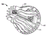
图7是包括集成驱动器的示例性装配的LED插座的透视图;7 is a perspective view of an exemplary assembled LED socket including an integrated driver;
图8是具有带边缘连接器的LED驱动器卡的替换实施例的透视图;Figure 8 is a perspective view of an alternate embodiment of an LED driver card with an edge connector;
图9是图8中的虚线9指定的区域的放大截面图。FIG. 9 is an enlarged cross-sectional view of a region designated by a dotted line 9 in FIG. 8 .
具体实施方式 Detailed ways
共同受让的2007年5月1日提交的美国专利申请序列号:11/742611公开了一种与集成驱动器插座一起使用的用于在照明器材中支撑高强度的LED的示例性安装组件,其在此通过参考而全部引入。Commonly assigned U.S. Patent Application Serial No. 11/742611 filed May 1, 2007 discloses an exemplary mounting assembly for supporting high intensity LEDs in a lighting fixture for use with an integrated driver socket that It is hereby incorporated by reference in its entirety.
参考图1和图7,LED连接器组件10的示例性实施例具有热沉18,该热沉具有凹槽的或鳍状的主体,提供用于散热的另外表面区域。热沉18设计有互补的外环11,类似于传统卤素灯泡,例如GU10或MR16类型的标准灯泡,这些灯泡在反射器组件上具有允许LED连接器组件10与传统灯泡可互换的外环。在另一实施例中,热沉18的螺纹后部(未示出)可以设置成拧入到螺纹照明器材(未示出)中。LED 28安装在印刷电路板(PCB)衬底或组件16上。LED PCB组件16搁置在空腔15内,该空腔配置成接收LEDPCB组件16。空腔15由圆周壁17限定,该圆周壁设置在从热沉18的外部半径径向向内突出的各个鳍部分31的一端。触头36插入到接触载体13中。触头36延伸到由鳍部分31限定的通道33中。鳍部分31将辐射热驱散到在邻近鳍部分31限定的通道34或空间中循环的周围空气。Referring to Figures 1 and 7, an exemplary embodiment of an
LED PCB组件16的触头19的数量取决于安装在LED PCB组件16上的LED 28的数量。LED PCB组件16包括两个接触垫19,用于具有单个LED28的LED PCB组件16,并且包含三个LED 28的LED PCB组件16包括四个接触垫19,尽管可以使用各种LED互连。例如红色、绿色、蓝色(RGB)LED包括共享共同的阳极连接的三个LED,使得四个接触垫19足以给三个LED供电。在附图中示出的触头36的数量仅是示例性的,并且不打算限制本发明的范围。触头载体13可以插入到设置在热沉18的一端的空腔15中。触头载体13安装到空腔15中,并且使得热触头抵靠LED PCB组件16,以保持LED PCB组件16在空腔15中适当的位置。锁紧环27安装在触头载体13上,并且渐进到凸缘部分11下方适当的位置,以固定触头载体13和可选择的透明透镜(未示出)。锁紧环27具有孔口25以允许光穿透。LED PCB组件16通过锁紧环而固定到位。锁紧环27推动触头36抵靠触垫19,用于正电接触,并且推动LED PCB组件16与热沉18热接触。触头载体13包括触头36,用于与LED PCB触头垫19匹配。LED PCB 16通过锁紧环27保持与热沉18热接触或连通。The number of
接下来参考图2和3,在凸缘部分11的方向上,通道34a-34d(例如参见图5)从热沉18的远端38沿轴向芯孔40延伸。LED驱动器卡20插入到轴向芯孔40的相对侧上的导向狭槽33。导向狭槽33配置成接收LED驱动器卡20。一对匹配的狭槽37设置在LED驱动器卡20中。匹配狭槽37相应于导向狭槽33中的端壁47以限制LED驱动器卡20在导向狭槽33中的行进,以及定位LED驱动器卡20,用于将触头36接收在邻近匹配狭槽37定位的插孔部分26中。LED驱动器卡20的保持力通过凹处37与定位在热沉18上的相应棘爪脊相配合而实现。Referring next to FIGS. 2 and 3 , in the direction of the
LED驱动器卡20包括集成电路(未示出),该集成电路调节各种电和电子参数,例如给LED PCB 16提供的恒定电流和电压。外部连接器21定位成邻近LED驱动器卡20的后边缘49。插孔部分26定位成邻近LED驱动器卡20的相对边缘51。外部连接器21包括例如通过焊接而连接到印刷电路垫41的导线35,用于将外部电源互连到LED驱动器卡20的内部迹线导体。外部连接器21可以是CT(共同端子)连接器,例如由宾夕法尼亚州米德尔顿的泰科电子公司制造的连接器,或任何合适的PCB连接器。在电子工业中,通常被称为表面安装技术(SMT)元件23、42的电子元件安装在LED驱动器卡20上。SMT元件23、42包括驱动器集成电路和无源电子元件,用于给LED PCB 16供电并控制LED PCB 16。SMT元件42、23安装在芯孔内部,具有足够的间隙,以避免当LED驱动器卡20插入到其中时被内壁52阻扰。
插孔部分26包括在导向边缘处的弹簧臂26a,用于接收触头36。弹簧臂26a具有相对的叶状部分26d,该叶状部分26d向内会聚到接触区域26f(例如参见图4),随后向外在远端分叉以形成导向区域,在该导向区域中,触头36进入插孔部分26。从插孔部分26横向突出的一对面板26b形成中空的框架部分26g。中空的框架部分26g围绕触头36,以将触头36的运动限制在中空框架部分26g中,从而避免触头36到热沉18或迹线或LED驱动器卡20上的其它导电表面的短路。示出的插孔部分26仅仅是一个实施例,并且在所附权利要求的范围内可以使用其它连接器布置,诸如卡边缘连接器(图8和9)或其它。The
参考图4,LED驱动器卡20包括表面区域54,该表面区域没有表面上的印刷电路迹线(未示出),如附图中的交叉影线所示。表面区域54设置成接近内壁52,并且LED驱动器卡20接合在狭槽33中,以防止迹线和热沉18之间可能的短路。Referring to FIG. 4, the
接下来参考图5,示出了LED驱动器卡20,该LED驱动器卡正插入到热沉18中和/或从热沉18中移除,运动的方向由箭头56所示。当使用相对的指定为34a和34b的一对通道时,插孔部分26与触头36匹配。第二对通道34c、34d布置成在从平面交叉通道34a、34b大约30°的轴向旋转处与第二组触头39对准。LED驱动器卡20可以选择性地插入到任一对通道34a、34b或34c、34d中,例如,两种不同颜色的LED设置在LED PCB 16上。替换地,触头36、39和相关联的通道34a-34d可以配置阻碍特征,以接收不同类型的板,用于驱动LED PCB 16上不同的元件。与通道对34a、34b和34c、34d相关联的两个位置允许柔性地连接到LED PCB 16上的不同垫构造。Referring next to FIG. 5 , there is shown the
接下来参考图6,示出了LED驱动器卡20的替换实施例。图6的实施例类似于图5的实施例,其中LED驱动器卡20包括具有外部绝缘壳59的替换插孔26,该外部绝缘壳使得插孔26隔离与热沉18电接触。插入运动由箭头56示出,并且通道34以与上文中相对于图5所述的相同方式操作。Referring next to Figure 6, an alternative embodiment of an
接下来参考图8和9,在替换实施例中,LED驱动器卡220和触头载体213通过卡边缘连接器布置连接。LED驱动器卡220包括LED驱动器卡220的上侧和下侧上的触头垫226,该触头垫226与触头236匹配。一对触头臂236a和236b形成叉形的触头236,该叉形的触头236以摩擦配合夹紧LED驱动器卡220的触头垫226。Referring next to Figures 8 and 9, in an alternative embodiment, the
本发明的优点是印刷电路(PC)板组件具有直接集成到LED像素组件的恒定电流驱动器电路。An advantage of the present invention is that the printed circuit (PC) board assembly has a constant current driver circuit integrated directly into the LED pixel assembly.
另一优点是PC驱动器板能够容易地、快速地且整体地装配到LED像素组件,并且不需要焊接或热粘合连接到LED像素组件。Another advantage is that the PC driver board can be easily, quickly and integrally assembled to the LED pixel assembly and does not require soldering or thermal adhesive connections to the LED pixel assembly.
Claims (10)
Applications Claiming Priority (5)
| Application Number | Priority Date | Filing Date | Title |
|---|---|---|---|
| US3231708P | 2008-02-28 | 2008-02-28 | |
| US61/032,317 | 2008-02-28 | ||
| US12/372,823 US8018136B2 (en) | 2008-02-28 | 2009-02-18 | Integrated LED driver for LED socket |
| US12/372,823 | 2009-02-18 | ||
| PCT/US2009/001222 WO2009108337A1 (en) | 2008-02-28 | 2009-02-26 | Integrated led driver for led socket |
Publications (2)
| Publication Number | Publication Date |
|---|---|
| CN101960204A CN101960204A (en) | 2011-01-26 |
| CN101960204B true CN101960204B (en) | 2013-06-12 |
Family
ID=41012650
Family Applications (1)
| Application Number | Title | Priority Date | Filing Date |
|---|---|---|---|
| CN2009801071266A Expired - Fee Related CN101960204B (en) | 2008-02-28 | 2009-02-26 | Integrated LED driver for LED socket |
Country Status (8)
| Country | Link |
|---|---|
| US (1) | US8018136B2 (en) |
| EP (1) | EP2257730B1 (en) |
| JP (1) | JP5376606B2 (en) |
| KR (1) | KR101139607B1 (en) |
| CN (1) | CN101960204B (en) |
| AT (1) | ATE545826T1 (en) |
| ES (1) | ES2381253T3 (en) |
| WO (1) | WO2009108337A1 (en) |
Families Citing this family (42)
| Publication number | Priority date | Publication date | Assignee | Title |
|---|---|---|---|---|
| DE102009054519A1 (en) * | 2009-12-10 | 2011-06-16 | Osram Gesellschaft mit beschränkter Haftung | Led lamp |
| DE102010001047A1 (en) * | 2010-01-20 | 2011-07-21 | Osram Gesellschaft mit beschränkter Haftung, 81543 | lighting device |
| TWI388766B (en) * | 2010-04-29 | 2013-03-11 | Cal Comp Electronics & Comm Co | Lamp structure |
| CN102906495B (en) | 2010-05-11 | 2016-08-24 | 皇家飞利浦电子股份有限公司 | Lighting module |
| JP5052647B2 (en) | 2010-05-31 | 2012-10-17 | シャープ株式会社 | Lighting device |
| KR101146303B1 (en) * | 2010-07-26 | 2012-05-21 | 금호전기주식회사 | Led electric bulb |
| KR101123132B1 (en) | 2010-09-03 | 2012-03-20 | 테크원 주식회사 | LED type bulb having replaceable power supply |
| JP5646264B2 (en) * | 2010-09-28 | 2014-12-24 | 株式会社小糸製作所 | Vehicle lighting |
| CN102109160B (en) * | 2011-03-30 | 2012-12-19 | 喻新立 | Surface mount type LED radiating fin, radiating unit and radiating system |
| TW201243228A (en) * | 2011-04-19 | 2012-11-01 | Everlight Electronics Co Ltd | Light emitting diode lamp and assembling method thereof |
| CN102748594A (en) * | 2011-04-19 | 2012-10-24 | 亿广科技(上海)有限公司 | Light emitting diode (LED) lamp and assembling method thereof |
| KR101127081B1 (en) * | 2011-05-25 | 2012-03-22 | 픽스테아주식회사 | Heat dissipating device for light emitter and light emitting lamp unit |
| CN102818136B (en) * | 2011-06-10 | 2015-01-07 | 海洋王照明科技股份有限公司 | Floodlight |
| US20130000881A1 (en) * | 2011-06-29 | 2013-01-03 | Bae Systems Information And Electronic Systems Integration Inc. | Passive heat exchanger for gimbal thermal management |
| US8746915B2 (en) * | 2011-07-29 | 2014-06-10 | Cree, Inc. | Light emitting die (LED) lamps, heat sinks and related methods |
| US8492961B2 (en) * | 2011-09-19 | 2013-07-23 | Osram Sylvania Inc. | Heat sink assembly |
| US8419225B2 (en) | 2011-09-19 | 2013-04-16 | Osram Sylvania Inc. | Modular light emitting diode (LED) lamp |
| CN103185281A (en) * | 2011-12-28 | 2013-07-03 | 富士迈半导体精密工业(上海)有限公司 | LED (Light Emitting Diode) bulb |
| US9170002B2 (en) * | 2012-01-05 | 2015-10-27 | Molex, Llc | Holder and LED module using same |
| US10066814B2 (en) * | 2012-01-11 | 2018-09-04 | Te Connectivity Corporation | Solid state lighting assembly |
| DE102012202353A1 (en) * | 2012-02-16 | 2013-08-22 | Osram Gmbh | Light module circuit board |
| US9175813B2 (en) * | 2012-03-30 | 2015-11-03 | 3M Innovative Properties Company | Electrical connectors for solid state light |
| TWI499740B (en) * | 2012-06-21 | 2015-09-11 | Acbel Polytech Inc | Light emitting diode bulb |
| JP2012199256A (en) * | 2012-07-24 | 2012-10-18 | Sharp Corp | Lighting system |
| CN104641175B (en) * | 2012-09-18 | 2018-08-10 | 飞利浦照明控股有限公司 | lamp with radiator |
| ES2616445T3 (en) * | 2012-09-18 | 2017-06-13 | Philips Lighting Holding B.V. | A lamp with a heat sink |
| WO2014167480A1 (en) | 2013-04-10 | 2014-10-16 | Koninklijke Philips N.V. | Lighting device and luminaire |
| DE102014101403A1 (en) * | 2013-05-15 | 2014-11-20 | Seidel GmbH & Co. KG | lighting device |
| CN104214730B (en) * | 2013-05-29 | 2017-05-31 | 海洋王(东莞)照明科技有限公司 | A kind of light fixture |
| US9022627B2 (en) | 2013-08-27 | 2015-05-05 | Osram Sylvania Inc. | Lens and retainer combination |
| CN104684130B (en) * | 2013-11-26 | 2017-04-19 | 四川新力光源股份有限公司 | Card-type LED driver and transportation vehicle with same |
| JP5501543B1 (en) * | 2014-01-15 | 2014-05-21 | シャープ株式会社 | Light bulb type lighting device |
| JP5501542B2 (en) * | 2014-01-15 | 2014-05-21 | シャープ株式会社 | Light bulb type lighting device |
| US20150226381A1 (en) * | 2014-02-10 | 2015-08-13 | Tse Min Chen | One-Piece Circuit Board-Based LED Lamp Bulb |
| DE202014100948U1 (en) | 2014-03-03 | 2015-06-09 | Zumtobel Lighting Gmbh | Luminaire with exchangeable lighting modules |
| US9951910B2 (en) * | 2014-05-19 | 2018-04-24 | Cree, Inc. | LED lamp with base having a biased electrical interconnect |
| US9702539B2 (en) | 2014-10-21 | 2017-07-11 | Cooper Technologies Company | Flow-through luminaire |
| KR101709394B1 (en) * | 2015-04-27 | 2017-02-23 | 한국광기술원 | Structure for connecting LED driver of LED down light |
| US10724724B2 (en) * | 2015-09-24 | 2020-07-28 | Philip Gustav Ericson | Lighting devices and methods |
| CN105388331B (en) * | 2015-12-14 | 2018-09-28 | 广州达测科技有限公司 | LED aging testers |
| CN105388330A (en) * | 2015-12-14 | 2016-03-09 | 江阴乐圩光电股份有限公司 | LED aging testing instrument |
| CN107613615B (en) * | 2017-09-06 | 2019-09-13 | 福建省光速达物联网科技股份有限公司 | A kind of unified light-dimming method of dimmable load |
Citations (1)
| Publication number | Priority date | Publication date | Assignee | Title |
|---|---|---|---|---|
| CN1574474A (en) * | 2003-05-27 | 2005-02-02 | 蒂科电子公司 | Electrical card edge connector with dual shorting contacts |
Family Cites Families (13)
| Publication number | Priority date | Publication date | Assignee | Title |
|---|---|---|---|---|
| DE8901434U1 (en) * | 1989-02-08 | 1990-06-21 | Grote & Hartmann Gmbh & Co Kg, 5600 Wuppertal | Contacting device for a light-emitting diode |
| US6016038A (en) | 1997-08-26 | 2000-01-18 | Color Kinetics, Inc. | Multicolored LED lighting method and apparatus |
| US6787999B2 (en) * | 2002-10-03 | 2004-09-07 | Gelcore, Llc | LED-based modular lamp |
| EP1673258A4 (en) | 2003-09-10 | 2010-12-15 | Robert D Galli | Flashlight housing |
| KR100593919B1 (en) * | 2004-07-01 | 2006-06-30 | 삼성전기주식회사 | LED module for vehicle headlight and vehicle headlight having same |
| JP4482706B2 (en) | 2005-04-08 | 2010-06-16 | 東芝ライテック株式会社 | Light bulb lamp |
| JP4569465B2 (en) * | 2005-04-08 | 2010-10-27 | 東芝ライテック株式会社 | lamp |
| JP5414274B2 (en) * | 2005-09-22 | 2014-02-12 | コーニンクレッカ フィリップス エヌ ヴェ | LED lighting module |
| US7588359B2 (en) * | 2005-09-26 | 2009-09-15 | Osram Sylvania Inc. | LED lamp with direct optical coupling in axial arrangement |
| US7985005B2 (en) * | 2006-05-30 | 2011-07-26 | Journée Lighting, Inc. | Lighting assembly and light module for same |
| US7738235B2 (en) | 2006-07-31 | 2010-06-15 | B/E Aerospace, Inc. | LED light apparatus |
| EP2163808B1 (en) * | 2007-05-23 | 2014-04-23 | Sharp Kabushiki Kaisha | Lighting device |
| TWM336390U (en) * | 2008-01-28 | 2008-07-11 | Neng Tyi Prec Ind Co Ltd | LED lamp |
-
2009
- 2009-02-18 US US12/372,823 patent/US8018136B2/en active Active
- 2009-02-26 CN CN2009801071266A patent/CN101960204B/en not_active Expired - Fee Related
- 2009-02-26 WO PCT/US2009/001222 patent/WO2009108337A1/en not_active Ceased
- 2009-02-26 KR KR1020107017808A patent/KR101139607B1/en not_active Expired - Fee Related
- 2009-02-26 EP EP09714701A patent/EP2257730B1/en not_active Not-in-force
- 2009-02-26 JP JP2010548724A patent/JP5376606B2/en not_active Expired - Fee Related
- 2009-02-26 ES ES09714701T patent/ES2381253T3/en active Active
- 2009-02-26 AT AT09714701T patent/ATE545826T1/en active
Patent Citations (1)
| Publication number | Priority date | Publication date | Assignee | Title |
|---|---|---|---|---|
| CN1574474A (en) * | 2003-05-27 | 2005-02-02 | 蒂科电子公司 | Electrical card edge connector with dual shorting contacts |
Also Published As
| Publication number | Publication date |
|---|---|
| JP5376606B2 (en) | 2013-12-25 |
| WO2009108337A1 (en) | 2009-09-03 |
| EP2257730B1 (en) | 2012-02-15 |
| KR101139607B1 (en) | 2012-05-07 |
| US20090218923A1 (en) | 2009-09-03 |
| CN101960204A (en) | 2011-01-26 |
| JP2011513917A (en) | 2011-04-28 |
| US8018136B2 (en) | 2011-09-13 |
| ATE545826T1 (en) | 2012-03-15 |
| KR20100107499A (en) | 2010-10-05 |
| ES2381253T3 (en) | 2012-05-24 |
| EP2257730A1 (en) | 2010-12-08 |
Similar Documents
| Publication | Publication Date | Title |
|---|---|---|
| CN101960204B (en) | Integrated LED driver for LED socket | |
| US7540761B2 (en) | LED connector assembly with heat sink | |
| JP6010116B2 (en) | Socket, lighting module, and lighting fixture | |
| US8231261B2 (en) | LED module and interconnection system | |
| CN101505010B (en) | Connection element to electrically connect an LED | |
| US9175813B2 (en) | Electrical connectors for solid state light | |
| JP5669188B2 (en) | LED lighting assembly | |
| JP3928384B2 (en) | LED lighting fixtures | |
| US8419225B2 (en) | Modular light emitting diode (LED) lamp | |
| US20130141913A1 (en) | Printed Circuit Board having at Least One Semiconductor Light Source, Support for the Printed Circuit Board, System Comprising the Printed Circuit Board and the Support, and Method for Mounting the Printed Circuit Board on the Support | |
| CN102906490B (en) | Lighting apparatus and the method for the manufacture of lighting apparatus | |
| WO2012014659A1 (en) | Connector and illumination device | |
| US9951910B2 (en) | LED lamp with base having a biased electrical interconnect | |
| CN106233069B (en) | Fixing base and LED information display system with fixing base | |
| JP3192284U (en) | LED tube lamp end assembly structure | |
| JP2020167123A (en) | Straight tube lamp | |
| KR20120105227A (en) | Connector and led lighting apparatus having the same |
Legal Events
| Date | Code | Title | Description |
|---|---|---|---|
| C06 | Publication | ||
| PB01 | Publication | ||
| C10 | Entry into substantive examination | ||
| SE01 | Entry into force of request for substantive examination | ||
| C14 | Grant of patent or utility model | ||
| GR01 | Patent grant | ||
| CP01 | Change in the name or title of a patent holder | ||
| CP01 | Change in the name or title of a patent holder |
Address after: American Pennsylvania Patentee after: Tailian Corporation Address before: American Pennsylvania Patentee before: Tyco Electronics Corp. |
|
| CF01 | Termination of patent right due to non-payment of annual fee | ||
| CF01 | Termination of patent right due to non-payment of annual fee |
Granted publication date: 20130612 Termination date: 20210226 |