CN101923647A - optical identification - Google Patents
optical identification Download PDFInfo
- Publication number
- CN101923647A CN101923647A CN2010102572261A CN201010257226A CN101923647A CN 101923647 A CN101923647 A CN 101923647A CN 2010102572261 A CN2010102572261 A CN 2010102572261A CN 201010257226 A CN201010257226 A CN 201010257226A CN 101923647 A CN101923647 A CN 101923647A
- Authority
- CN
- China
- Prior art keywords
- signature
- item
- article
- scan
- image
- Prior art date
- Legal status (The legal status is an assumption and is not a legal conclusion. Google has not performed a legal analysis and makes no representation as to the accuracy of the status listed.)
- Granted
Links
Images


Classifications
-
- G—PHYSICS
- G03—PHOTOGRAPHY; CINEMATOGRAPHY; ANALOGOUS TECHNIQUES USING WAVES OTHER THAN OPTICAL WAVES; ELECTROGRAPHY; HOLOGRAPHY
- G03G—ELECTROGRAPHY; ELECTROPHOTOGRAPHY; MAGNETOGRAPHY
- G03G21/00—Arrangements not provided for by groups G03G13/00 - G03G19/00, e.g. cleaning, elimination of residual charge
- G03G21/04—Preventing copies being made of an original
- G03G21/046—Preventing copies being made of an original by discriminating a special original, e.g. a bank note
-
- G—PHYSICS
- G06—COMPUTING OR CALCULATING; COUNTING
- G06F—ELECTRIC DIGITAL DATA PROCESSING
- G06F16/00—Information retrieval; Database structures therefor; File system structures therefor
- G06F16/20—Information retrieval; Database structures therefor; File system structures therefor of structured data, e.g. relational data
- G06F16/24—Querying
- G06F16/245—Query processing
- G06F16/2455—Query execution
- G06F16/24553—Query execution of query operations
- G06F16/24561—Intermediate data storage techniques for performance improvement
-
- G—PHYSICS
- G06—COMPUTING OR CALCULATING; COUNTING
- G06F—ELECTRIC DIGITAL DATA PROCESSING
- G06F16/00—Information retrieval; Database structures therefor; File system structures therefor
-
- G—PHYSICS
- G06—COMPUTING OR CALCULATING; COUNTING
- G06F—ELECTRIC DIGITAL DATA PROCESSING
- G06F16/00—Information retrieval; Database structures therefor; File system structures therefor
- G06F16/30—Information retrieval; Database structures therefor; File system structures therefor of unstructured textual data
- G06F16/33—Querying
- G06F16/3331—Query processing
-
- G—PHYSICS
- G06—COMPUTING OR CALCULATING; COUNTING
- G06K—GRAPHICAL DATA READING; PRESENTATION OF DATA; RECORD CARRIERS; HANDLING RECORD CARRIERS
- G06K7/00—Methods or arrangements for sensing record carriers, e.g. for reading patterns
- G06K7/10—Methods or arrangements for sensing record carriers, e.g. for reading patterns by electromagnetic radiation, e.g. optical sensing; by corpuscular radiation
-
- G—PHYSICS
- G06—COMPUTING OR CALCULATING; COUNTING
- G06T—IMAGE DATA PROCESSING OR GENERATION, IN GENERAL
- G06T7/00—Image analysis
- G06T7/40—Analysis of texture
-
- G—PHYSICS
- G06—COMPUTING OR CALCULATING; COUNTING
- G06V—IMAGE OR VIDEO RECOGNITION OR UNDERSTANDING
- G06V10/00—Arrangements for image or video recognition or understanding
- G06V10/10—Image acquisition
- G06V10/12—Details of acquisition arrangements; Constructional details thereof
- G06V10/14—Optical characteristics of the device performing the acquisition or on the illumination arrangements
- G06V10/141—Control of illumination
-
- G—PHYSICS
- G06—COMPUTING OR CALCULATING; COUNTING
- G06V—IMAGE OR VIDEO RECOGNITION OR UNDERSTANDING
- G06V10/00—Arrangements for image or video recognition or understanding
- G06V10/10—Image acquisition
- G06V10/12—Details of acquisition arrangements; Constructional details thereof
- G06V10/14—Optical characteristics of the device performing the acquisition or on the illumination arrangements
- G06V10/147—Details of sensors, e.g. sensor lenses
-
- G—PHYSICS
- G06—COMPUTING OR CALCULATING; COUNTING
- G06V—IMAGE OR VIDEO RECOGNITION OR UNDERSTANDING
- G06V10/00—Arrangements for image or video recognition or understanding
- G06V10/40—Extraction of image or video features
- G06V10/42—Global feature extraction by analysis of the whole pattern, e.g. using frequency domain transformations or autocorrelation
- G06V10/431—Frequency domain transformation; Autocorrelation
-
- G—PHYSICS
- G06—COMPUTING OR CALCULATING; COUNTING
- G06V—IMAGE OR VIDEO RECOGNITION OR UNDERSTANDING
- G06V10/00—Arrangements for image or video recognition or understanding
- G06V10/70—Arrangements for image or video recognition or understanding using pattern recognition or machine learning
- G06V10/74—Image or video pattern matching; Proximity measures in feature spaces
- G06V10/75—Organisation of the matching processes, e.g. simultaneous or sequential comparisons of image or video features; Coarse-fine approaches, e.g. multi-scale approaches; using context analysis; Selection of dictionaries
- G06V10/751—Comparing pixel values or logical combinations thereof, or feature values having positional relevance, e.g. template matching
- G06V10/7515—Shifting the patterns to accommodate for positional errors
-
- G—PHYSICS
- G06—COMPUTING OR CALCULATING; COUNTING
- G06V—IMAGE OR VIDEO RECOGNITION OR UNDERSTANDING
- G06V10/00—Arrangements for image or video recognition or understanding
- G06V10/94—Hardware or software architectures specially adapted for image or video understanding
- G06V10/95—Hardware or software architectures specially adapted for image or video understanding structured as a network, e.g. client-server architectures
-
- G—PHYSICS
- G06—COMPUTING OR CALCULATING; COUNTING
- G06V—IMAGE OR VIDEO RECOGNITION OR UNDERSTANDING
- G06V20/00—Scenes; Scene-specific elements
- G06V20/80—Recognising image objects characterised by unique random patterns
-
- G—PHYSICS
- G07—CHECKING-DEVICES
- G07D—HANDLING OF COINS OR VALUABLE PAPERS, e.g. TESTING, SORTING BY DENOMINATIONS, COUNTING, DISPENSING, CHANGING OR DEPOSITING
- G07D7/00—Testing specially adapted to determine the identity or genuineness of valuable papers or for segregating those which are unacceptable, e.g. banknotes that are alien to a currency
- G07D7/004—Testing specially adapted to determine the identity or genuineness of valuable papers or for segregating those which are unacceptable, e.g. banknotes that are alien to a currency using digital security elements, e.g. information coded on a magnetic thread or strip
-
- G—PHYSICS
- G07—CHECKING-DEVICES
- G07D—HANDLING OF COINS OR VALUABLE PAPERS, e.g. TESTING, SORTING BY DENOMINATIONS, COUNTING, DISPENSING, CHANGING OR DEPOSITING
- G07D7/00—Testing specially adapted to determine the identity or genuineness of valuable papers or for segregating those which are unacceptable, e.g. banknotes that are alien to a currency
- G07D7/06—Testing specially adapted to determine the identity or genuineness of valuable papers or for segregating those which are unacceptable, e.g. banknotes that are alien to a currency using wave or particle radiation
- G07D7/12—Visible light, infrared or ultraviolet radiation
- G07D7/121—Apparatus characterised by sensor details
-
- G—PHYSICS
- G07—CHECKING-DEVICES
- G07D—HANDLING OF COINS OR VALUABLE PAPERS, e.g. TESTING, SORTING BY DENOMINATIONS, COUNTING, DISPENSING, CHANGING OR DEPOSITING
- G07D7/00—Testing specially adapted to determine the identity or genuineness of valuable papers or for segregating those which are unacceptable, e.g. banknotes that are alien to a currency
- G07D7/06—Testing specially adapted to determine the identity or genuineness of valuable papers or for segregating those which are unacceptable, e.g. banknotes that are alien to a currency using wave or particle radiation
- G07D7/12—Visible light, infrared or ultraviolet radiation
- G07D7/128—Viewing devices
-
- G—PHYSICS
- G07—CHECKING-DEVICES
- G07D—HANDLING OF COINS OR VALUABLE PAPERS, e.g. TESTING, SORTING BY DENOMINATIONS, COUNTING, DISPENSING, CHANGING OR DEPOSITING
- G07D7/00—Testing specially adapted to determine the identity or genuineness of valuable papers or for segregating those which are unacceptable, e.g. banknotes that are alien to a currency
- G07D7/20—Testing patterns thereon
-
- G—PHYSICS
- G09—EDUCATION; CRYPTOGRAPHY; DISPLAY; ADVERTISING; SEALS
- G09C—CIPHERING OR DECIPHERING APPARATUS FOR CRYPTOGRAPHIC OR OTHER PURPOSES INVOLVING THE NEED FOR SECRECY
- G09C1/00—Apparatus or methods whereby a given sequence of signs, e.g. an intelligible text, is transformed into an unintelligible sequence of signs by transposing the signs or groups of signs or by replacing them by others according to a predetermined system
-
- G—PHYSICS
- G09—EDUCATION; CRYPTOGRAPHY; DISPLAY; ADVERTISING; SEALS
- G09C—CIPHERING OR DECIPHERING APPARATUS FOR CRYPTOGRAPHIC OR OTHER PURPOSES INVOLVING THE NEED FOR SECRECY
- G09C5/00—Ciphering apparatus or methods not provided for in the preceding groups, e.g. involving the concealment or deformation of graphic data such as designs, written or printed messages
Landscapes
- Engineering & Computer Science (AREA)
- Physics & Mathematics (AREA)
- General Physics & Mathematics (AREA)
- Theoretical Computer Science (AREA)
- Health & Medical Sciences (AREA)
- General Health & Medical Sciences (AREA)
- Multimedia (AREA)
- Toxicology (AREA)
- Computer Vision & Pattern Recognition (AREA)
- Databases & Information Systems (AREA)
- Software Systems (AREA)
- General Engineering & Computer Science (AREA)
- Data Mining & Analysis (AREA)
- Artificial Intelligence (AREA)
- Computer Security & Cryptography (AREA)
- Vascular Medicine (AREA)
- Medical Informatics (AREA)
- Evolutionary Computation (AREA)
- Computing Systems (AREA)
- Computational Linguistics (AREA)
- Electromagnetism (AREA)
- Inspection Of Paper Currency And Valuable Securities (AREA)
- Credit Cards Or The Like (AREA)
- Collating Specific Patterns (AREA)
- Lenses (AREA)
- Image Input (AREA)
- Image Processing (AREA)
- Editing Of Facsimile Originals (AREA)
- Mechanical Optical Scanning Systems (AREA)
Abstract
本发明提供了一种装置,用于确定来自该装置的读取体内的物品的签名。该装置包括:源,其用于产生相干光束;以及光束引导元件,其用于将所述相干光束引导到所述读取体内。该装置还可以包括:检测器设备,用于收集由所述读取体内的相干光束的散射创建的信号,其中所述信号中不同的信号与来自所述读取体的不同部分的散射相关,所述检测器设备具有大于预定的最小值的数值孔径;以及处理器,其用于从收集的信号确定所述读取体内的物品的签名。当需要测试物品的真实性时,可以重复这种装置的使用。使用这种系统,发现由于可从各种日常物品中以直接的方式测量唯一特性,所以制作特别准备的标记的努力和花费基本是毫无意义的。
The present invention provides a device for determining a signature of an item in a read body from the device. The apparatus includes a source for generating a coherent light beam and a beam directing element for directing the coherent light beam into the reading volume. The apparatus may further comprise a detector device for collecting signals created by scattering of a coherent light beam within said reading volume, wherein different ones of said signals relate to scattering from different parts of said reading volume, The detector device has a numerical aperture greater than a predetermined minimum; and a processor for determining a signature of an item in the read body from the collected signals. The use of such a device can be repeated when it is desired to test the authenticity of the item. Using such a system, it was found that the effort and expense of making specially prepared markings is essentially pointless since unique properties can be measured in a direct manner from various everyday objects.
Description
本发明是申请日为2006年12月22日、申请号为200680053240.1且发明名称为“光学鉴别”的发明专利申请的分案申请。The present invention is a divisional application of an invention patent application with an application date of December 22, 2006, an application number of 200680053240.1, and an invention title of "optical identification".
技术领域technical field
本发明涉及鉴别,并且更具体地但非排他地,涉及用于物品鉴别的方法和装置。The present invention relates to authentication, and more particularly, but not exclusively, to methods and apparatus for article authentication.
背景技术Background technique
许多传统的鉴别安全系统依赖于除制造商之外的任何人都难以进行的工艺,其中该难度可能是由固定设备的花费、技术诀窍的复杂性或最好这两者带来的。例子有在银行票据上提供水印和在信用卡或护照上提供全息图。不幸的是,罪犯越来越老练,并且几乎可以再现原始制造商可以制作的任何东西。Many traditional authentication security systems rely on processes that are difficult for anyone but the manufacturer, where the difficulty may be brought about by capital equipment expense, know-how complexity, or best of both. Examples are providing watermarks on bank notes and holograms on credit cards or passports. Unfortunately, criminals are getting more sophisticated and can reproduce almost anything the original manufacturer can make.
因此,已知一种方案的鉴别安全系统,其依赖于使用受自然规律支配的某个处理创建安全标记(token),这样使得每个标记都是唯一的,并且更重要地具有可测量并且因此可用作后续验证的基础的唯一特性。根据该方案,按照设定的方法制造并且测量标记以便获得唯一特性。该特性可被存储在计算机数据库内或者以其他方式被保留。这种类型的标记可被嵌入到承载物品,例如,银行票据、护照、ID卡、重要文档。随后,该承载物品可被再次测量,并且将测得的特性与存储在数据库内的特性进行比较以便确定是否匹配。Thus, there is known an approach to authentication security systems that relies on creating security tokens using some process governed by the laws of nature such that each token is unique and more importantly measurable and thus A unique characteristic that can be used as the basis for subsequent validation. According to this scheme, markings are produced according to a set method and measured in order to obtain unique characteristics. This characteristic may be stored in a computer database or otherwise maintained. This type of marking can be embedded into carrier objects, eg bank notes, passports, ID cards, important documents. Subsequently, the load item may be measured again and the measured characteristics compared to those stored in the database to determine a match.
在该通常的方案中,已经提出使用不同的物理效应。在PCT/GB03/03917中,已经考虑的一种效应是测量来自磁性材料淀积的磁响应特性,其中每个样本具有由于磁材料中以不可复现的方式形成的自然出现的瑕疵而带来的唯一的磁响应。在若干现有技术文档中已经考虑了另一种效应是利用由于物品的内在属性而产生的激光散斑来提供唯一的特性。In this general approach, it has been proposed to use different physical effects. In PCT/GB03/03917, one effect that has been considered is the measurement of the magnetic response properties from the deposition of magnetic material, where each sample has unique magnetic response. Another effect that has been considered in several prior art documents is the use of laser speckle due to intrinsic properties of the item to provide unique characteristics.
GB2221870A公开了如下一种方法,其中诸如ID卡的安全设备上被显著地浮雕以标记。该标记的形式是源自母板(master)的结构化表面。由光散射结构产生的散斑图案是该母板特有的,并且因此可被测量,以便证明该安全设备上的标记的真实性。在读取器中测量该安全设备上的标记,该读取器具有用于产生大小约等于该标记(直径为2mm)的相干光束的激光器以及电荷耦合器件(CCD)阵列检测器,该CCD阵列检测器用于测量来自该标记的对激光的各种反射之间的干涉产生的散斑图案。结果数据被记录。为了进行验证,可将安全设备放置在读取器内,并且将所记录的散斑图案信号与来自参照设备的根据相同母板创建的类似的记录信号进行比较。GB2221870A discloses a method in which a security device such as an ID card is prominently embossed with a mark. The form of this mark is derived from the structured surface of the master. The speckle pattern produced by the light scattering structures is specific to the master and can therefore be measured in order to prove the authenticity of the indicia on the security device. The marking on the security device is measured in a reader having a laser for generating a coherent beam approximately the size of the marking (2 mm in diameter) and a charge-coupled device (CCD) array detector that detects A detector is used to measure the speckle pattern produced by the interference between the various reflections of the laser light from the mark. The resulting data is recorded. For verification, a security device can be placed inside the reader and the recorded speckle pattern signal is compared to a similar recorded signal from a reference device created from the same master.
US6,584,214描述了使用来自特别制备的表面结构的反射中的散斑图案的另一种选择,其中相反散斑图案用在来自特别制备的透明标记的透射中。该技术的优选实施是制备尺寸近似为1cm×1cm、其中嵌有玻璃球的环氧标记。标记是这样制备的,即将玻璃球混入液体聚合物的胶状悬浮液中,然后将其固化以便固定玻璃球的位置。然后利用定位用来测量散斑图案的CCD阵列检测器使用透射相干激光束来探查玻璃球的唯一的信号群(ensemble)。在对该方案的改进中,已知的标识符被编码在反射表面上,然后将该反射表面贴到该标记的一侧。探查光穿过标记,被已知标识符反射,并且再次穿过该标记。因此,玻璃球改变了散斑图案,从而根据该已知标识符产生了唯一的散列密钥。US 6,584,214 describes an alternative to using speckle patterns in reflection from specially prepared surface structures, where the opposite speckle pattern is used in transmission from specially prepared transparent markings. A preferred implementation of this technique is the preparation of epoxy markers approximately 1 cm x 1 cm in size with glass spheres embedded in them. The markers are made by mixing glass spheres into a colloidal suspension of liquid polymer, which is then cured to hold the spheres in place. A unique ensemble of glass spheres is then probed using a transmitted coherent laser beam with a CCD array detector positioned to measure the speckle pattern. In a refinement of this scheme, a known identifier is encoded on a reflective surface which is then affixed to one side of the mark. The probing light passes through the mark, is reflected by the known identifier, and passes through the mark again. Thus, the glass sphere changes the speckle pattern, resulting in a unique hash key based on this known identifier.
R Anderson(在答复文章“Plastic tag makes foolproof ID”Technology Research News,2002年10月2日的信中)简要报告了上世纪80年代美国Sandia国家实验室的工作人员试验了一种特殊的银行票据纸,该纸浸有短切光纤。可以测量来自这些光纤的散斑图案,并且将该散斑图案的数字签名版本作为条形码印刷在票据的一侧上。然而,Anderson报告该构想无法正常工作,因为光纤太易碎,而当银行票据流通时该散斑图案由于磨损而迅速改变。这意味着从使用后的银行票据内的光纤测量的散斑图案不再与条形码匹配,从而不再能够按照预期的方式根据散斑图案鉴别银行票据。R Anderson (in a letter in reply to the article "Plastic tag makes foolproof ID" Technology Research News, October 2, 2002) briefly reported that in the 1980s, the staff of the Sandia National Laboratory in the United States experimented with a special bank note Paper impregnated with chopped optical fibers. The speckle pattern from these fibers can be measured and a digitally signed version of the speckle pattern printed as a barcode on one side of the document. However, Anderson reports that the idea didn't work because the fiber is too fragile, and the speckle pattern changes rapidly due to wear and tear when bank notes are in circulation. This means that the speckle pattern measured from the optical fiber inside the used bank note no longer matches the barcode, so that the bank note can no longer be identified based on the speckle pattern as intended.
Anderson在他的2001年的教科书(R Anderson“SecurityEngineering:a guide to building dependable distributed systems”Wiley 2001,251-252页ISBN 0-471-38922-6)的第251页中还简要提及了看起来与他的信中所描述的方案类似的用于监视军备控制协议的方案。Anderson注意到许多材料具有独特或可以通过以少量的炸药冲蚀而形成的表面。据称这样使得容易识别诸如重型炮的固定设备,其中通过识别每个炮筒就足以防止被军事控制协议的任何一方所欺骗。Anderson报告使用激光散斑技术测量炮筒的表面图案,并且或是将其记录在日志中或是作为机器可读的数字签名附到设备上。Anderson also briefly mentions what appears to be A program for monitoring arms control agreements similar to the one described in his letter. Anderson notes that many materials have surfaces that are unique or can be formed by erosion with small amounts of explosives. This is said to allow easy identification of fixed equipment such as heavy guns, where identifying each barrel is sufficient to prevent being tricked by either party to a military control agreement. Anderson reports using laser speckle technology to measure the surface pattern of the gun barrel and either log it or attach it to the device as a machine-readable digital signature.
代替使用激光散斑,还提出了一组更直接的方案,它们简单地以高分辨率成像物品,并且使用该高分辨率的图像作为唯一特性,该唯一特性随后可被再次成像以便验证真实性。这可被认为是对用于警方保持的指纹库的传统方案的适应性改变。Instead of using laser speckle, a set of more straightforward schemes have also been proposed that simply image the item at high resolution and use this high resolution image as a unique feature that can then be imaged again to verify authenticity . This can be considered an adaptation of the traditional approach for police-maintained fingerprint banks.
US5,521,984提出使用光学显微镜拍摄贵重物品(例如,绘画、雕塑、邮票、宝石或特定文档)的一小部分。US5,521,984 proposes the use of an optical microscope to photograph a small portion of a valuable object (eg a painting, sculpture, stamp, gemstone or specific document).
Anderson在他的2001年的教科书的第252页上报告,邮政系统正在考虑这种基于用显微镜直接成像信封的方案。报告了拍摄信封的纸纤维的图像,提取图案,并且将其记录在数字签名的邮资标记内。Anderson reports on page 252 of his 2001 textbook that the postal system is considering such a scheme based on direct imaging of envelopes with a microscope. reported taking an image of the paper fibers of an envelope, extracting the pattern, and recording it within the digitally signed postage indicium.
US5,325,167提出以类似的方案对宝贵文档的一部分上的调色剂微粒的颗粒结构进行成像。US 5,325,167 proposes a similar approach to imaging the granular structure of toner particles on a portion of a valuable document.
通过这个先前的工作,存在对于理想的验证方案来说是明显的各种所希望的特征。From this prior work, there are various desirable features that are evident for an ideal authentication scheme.
所报告的基于磁或散斑的技术看起来能够提供高的安全等级,但是需要制备用于实际操作的特殊材料以便确保被探查的结构的长期稳定性。在许多情况下,将标记集成到要保护的物品内不是轻而易举的。尤其是,将树脂标记或磁芯片集成到纸张或卡板内是不容易的并且会导致不菲的开销。为了与纸张或卡板集成,理想地任何标记都应该是可印刷的。另外,基于可附标记的方案的固有的安全风险在于,标记潜在地可分离并且可附于其他物品。The reported magnetic or speckle-based techniques appear to provide a high level of security, but require the preparation of special materials for practical operation in order to ensure the long-term stability of the probed structures. In many cases, integrating markings into the item to be protected is not trivial. In particular, integrating resin markers or magnetic chips into paper or cardboard is not easy and results in considerable expense. Ideally any markings should be printable for integration with paper or cardboard. Additionally, an inherent security risk of an approach based on attachable marks is that the marks are potentially detachable and attachable to other items.
所报告的直接成像技术具有这样的优点,即,它们直接从物品获得其数字签名,由此避免了对特殊标记的需要。然而,它们固有的安全性很低。例如,它们易受到对存储的图像数据的欺骗性访问,这可能允许产生一个物品的被不正确地验证为真品的伪造品,或易于通过简单地使用高分辨率打印机打印当查看真品的相关部分时将在显微镜下被看到的图像而伪造。直接成像技术的安全等级还与图像数据量成比例,这迫使使用昂贵的高分辨率成像装置用于较高安全等级。这对于某些应用是可以接受的,例如邮政分拣或银行票据验证,但是在许多应用中将是不可接受的。The reported direct imaging techniques have the advantage that they obtain their digital signature directly from the item, thereby avoiding the need for special markings. However, they are inherently less secure. For example, they are vulnerable to fraudulent access to stored image data, which may allow the creation of a counterfeit of an item incorrectly authenticated as genuine, or to be easily viewed by simply using a high-resolution printer to print out relevant parts of the genuine article. Forged images that would then be seen under a microscope. The security level of direct imaging techniques is also proportional to the amount of image data, which necessitates the use of expensive high-resolution imaging devices for higher security levels. This is acceptable for some applications, such as postal sorting or bank note verification, but will not be acceptable in many applications.
另外,James D.R.Buchanan等在“Forgery:‘Fingerprinting’documents and packaging”,Nature 436,475-475(2005年7月28日)中描述了一种使用来自物品的反射激光以本领域前所未有的高度可再现性唯一地识别物品。Buchanan的技术在物品表面上的多个点中的每个点处若干次地采样来自该表面的反射,以创建该物品的签名或“指印”。In addition, James D.R. Buchanan et al. in "Forgery: 'Fingerprinting' documents and packaging", Nature 436, 475-475 (July 28, 2005) describe a method of using reflected laser light from objects to achieve a high degree of reliability unprecedented in the field. Reproducibility uniquely identifies items. Buchanan's technique samples reflections from the surface of an item several times at each of multiple points on the surface to create a signature or "fingerprint" of the item.
发明内容Contents of the invention
至少部分地考虑了传统系统的问题和缺点做出本发明。The present invention has been made in consideration, at least in part, of the problems and disadvantages of conventional systems.
本发明产生于发明人关于应用基于光学的鉴别技术的工作,其中由物品表面上的不可再现元素提供物品的唯一性(参见上文中的Buchanan)。The present invention arose out of the inventor's work on the application of optically based authentication techniques, where the uniqueness of the item is provided by non-reproducible elements on the item's surface (see Buchanan, supra).
作为该工作的一部分,发现来自物品的反射或透射图案包括两个角频率大不相同的分量。高角频率分量(传统上被称为“散斑”)对于目标物品和入射激光的相对定位的扰动极其敏感。取决于物品的材料和激光的属性,在相对于期望入射角只有小如0.1度的角度扰动时就可以出现反射图案的完全改变。然而,低角频率分量(“非散斑”分量)对于这种角度扰动非常有弹性。As part of this work, it was found that a reflected or transmitted pattern from an article includes two components with substantially different angular frequencies. High angular frequency components (traditionally referred to as "speckle") are extremely sensitive to perturbations in the relative positioning of the target item and the incident laser light. Depending on the material of the item and the properties of the laser, a complete change in the reflection pattern can occur with as little as 0.1 degrees of angular perturbation relative to the desired angle of incidence. However, low angular frequency components ("non-speckle" components) are very resilient to such angular perturbations.
根据进一步的调查,确定许多非制备的表面,诸如各种纸张、卡板和塑料的表面,都表现出相同的效果。然而,本发明人已经确定可以仅从非散斑成分确定唯一特性。因此,在散斑效应创建唯一的签名时,非散斑元素可用于提供比仅使用散斑的情况更可靠和更可再现的签名。Upon further investigation, it was determined that many non-prepared surfaces, such as various paper, cardboard and plastic surfaces, exhibited the same effect. However, the inventors have determined that unique properties can be determined only from non-speckle components. Therefore, while the speckle effect creates a unique signature, the non-speckle elements can be used to provide a more reliable and reproducible signature than if only speckle were used.
因此已经发现,可以获得基于散斑的技术的所有优点而不必使用特别制备的标记或以其它方式特别制备物品。具体地,已经发现许多类型的纸张和卡板因相干光束而给出唯一特性的散射信号,从而可以从包裹物件的几乎任何纸件文档或卡板获得唯一的数字签名。另外,通过采用具有此处描述的特性的系统,从而以高的数值孔径对每单个目标区域采样,可以显著提高系统对目标的角度偏差和来自背景照明的干扰的鲁棒性。另外,通过采用从大的目标表面区域采样的系统,可以显著提高系统对目标的平移偏差的鲁棒性。It has thus been found that all the advantages of speckle-based techniques can be obtained without having to use specially prepared markers or otherwise specially prepare the article. In particular, it has been found that many types of paper and cardboard give unique characteristic scatter signals due to coherent light beams, so that a unique digital signature can be obtained from almost any paper document or cardboard wrapping an item. Additionally, by employing a system with the properties described here, whereby each individual target region is sampled at a high numerical aperture, the robustness of the system to angular deviations of the target and interference from background illumination can be significantly improved. Additionally, by employing a system that samples from a large target surface area, the robustness of the system to translational biases of the target can be significantly improved.
用于安全设备的大部分上述现有的散斑读取器看来都基于以准直的(即,未聚焦)的激光束照亮整个标记,并且以CCD对得到的散斑图案的有效立体角部分成像[GB2221870,US6,584,214],从而获得由大的数据点矩阵构成的该标记的散斑图案图像。Most of the above-mentioned existing speckle readers for security devices appear to be based on illuminating the entire mark with a collimated (i.e. unfocused) laser beam and effective stereoscopic imaging of the resulting speckle pattern with the CCD. The corner portion is imaged [GB2221870, US6,584,214] to obtain a speckle pattern image of the mark consisting of a large matrix of data points.
发明人使用的读取器不以这种方式操作。实际上,本发明的检测器不能使用覆盖大部分目标区域的未聚焦束,这是由于这使得低角频率的非散斑分量变得模糊,从而仅有散斑部分被读取。当然光束被理解为在入射到目标表面时具有有限面积,但是该入射面积越大,反射的非散斑分量越模糊。The reader used by the inventors does not operate in this way. In fact, the detector of the present invention cannot use an unfocused beam covering most of the target area, since this blurs the non-speckle components at low angular frequencies so that only the speckle part is read. Of course the light beam is understood to have a finite area when it is incident on the target surface, but the larger this incident area is, the more blurred is the non-speckle component of the reflection.
本申请的发明人使用的读取器读取超过大到足以平均掉反射或折射光中更多的不可靠的散斑部分的立体角的非散斑分量。通过这样做,由读取器产生的签名可以有效地忽略反射或折射光的散斑分量,从而即使在对给定物品的不同扫描之间出现该物品相对于读取器的定位扰动时,也能创建该物品的可再现的签名。The inventors of the present application used a reader that reads the non-speckle component over a solid angle large enough to average out the more unreliable speckle portion of reflected or refracted light. By doing so, the signature produced by the reader can effectively ignore the speckle component of reflected or refracted light, thereby allowing even perturbations in the positioning of a given item relative to the reader between different scans of that item. A reproducible signature of the item can be created.
从一个角度看,本发明的扫描器操作为采样来自表面的一个或多个反射图像中的各个“像素”或点。扫描器中的每个光电检测器对不同的反射图像进行采样。通过一次采样单个点,来自表面上的其它点的反射量不会干扰采样数据。由此可以记录反射图像内的低频分量,从而允许大量忽略位置敏感的散斑(高频)分量。表面上的反射图像从其被采样的每个位置代表每个反射图像中的不同“像素”。Viewed from one perspective, the scanner of the present invention operates to sample individual "pixels" or points in one or more reflected images from a surface. Each photodetector in the scanner samples a different reflected image. By sampling a single point at a time, the amount of reflections from other points on the surface do not interfere with the sampled data. Low-frequency components within the reflected image can thereby be recorded, allowing largely disregarded position-sensitive speckle (high-frequency) components. Each location on the surface from which the reflected image is sampled represents a different "pixel" in each reflected image.
在一个例子中,提供了具有单个光电检测器以便收集从物品表面反射的信号分量的读取器。入射到该表面上的激光束聚焦为仅覆盖该表面的一小部分的光斑。当光束和表面彼此相对移动时,从该表面的不同局部区域收集信号。因此,来自该物品的特性响应由来自物品表面上大量(典型地,几百或几千)不同局部区域的独立的测量构成。虽然在这个例子中使用单个光电检测器,但是也可以增加其它的光电检测器以获得更高的安全级别。In one example, a reader is provided having a single photodetector to collect signal components reflected from the surface of the item. A laser beam incident on the surface is focused into a spot covering only a small portion of the surface. As the beam and surface move relative to each other, signals are collected from different localized areas of the surface. Thus, the characteristic response from the article consists of independent measurements from a large number (typically hundreds or thousands) of different localized areas on the article's surface. Although a single photodetector is used in this example, other photodetectors can be added for higher levels of security.
根据本发明的一个方面,由此提供了一种用于确定来自布置在读取体(reading volume)内的物品的签名的装置。该装置可以包括可操作为产生相干光束的源和可操作为将该相干光束引导到读取体中的光束引导元件。该装置还可以包括检测器设备,用于收集由所述读取体内的相干光束的散射所生成的信号,其中所述信号中不同的信号与来自所述读取体的不同部分的散射有关,所述检测器设备具有大于预定最小值的数值孔径和可操作为根据收集到的信号确定所述读取体内的物品的签名的处理器。从而可以按照避免过度依赖反射信号中的角度定位敏感的高角频率分量的方式确定物品的签名。此同一效果还提供了对表面劣化的弹性,表面劣化可能具有相对于所述表面带来光学的有效角度扰动的效果。例如,表面上的水就可以改变该表面的角度。通过在所述检测器中使用大的数值孔径,可以相对于构成传统的散斑信号的高角频率分量强调反射信号中的低角频率分量。与传统的散斑高角频率分量相比,反射信号中的低角频率分量对目标的角度扰动不敏感得多。According to one aspect of the invention, there is thus provided an apparatus for determining a signature from an item arranged in a reading volume. The apparatus may include a source operable to generate a coherent beam and a beam directing element operable to direct the coherent beam into the reading volume. The apparatus may further comprise detector means for collecting signals generated by scattering of the coherent light beam within said reading volume, wherein different ones of said signals relate to scattering from different parts of said reading volume, The detector device has a numerical aperture greater than a predetermined minimum and a processor operable to determine a signature of an item in the reading body from the collected signals. The signature of the item can thereby be determined in a manner that avoids over-reliance on angular localization sensitive high angular frequency components in the reflected signal. This same effect also provides resilience to surface degradation which may have the effect of bringing optically significant angular perturbations relative to said surface. For example, water on a surface can change the angle of that surface. By using a large numerical aperture in the detector, the low angular frequency components in the reflected signal can be emphasized relative to the high angular frequency components that make up a conventional speckle signal. Compared with the high angular frequency components of traditional speckle, the low angular frequency components in the reflected signal are much less sensitive to the angular perturbation of the target.
在某些实施例中,通过使得在不同时刻对所述读取体的不同部分进行照明,并且在给定时间测量来自经受局部照明的点的散射,来确保数据点中的不同数据点与来自所述读取体的不同部分的散射有关。通过采取这样的设置,该系统对目标相对于所述装置的平移扰动是有弹性的。In some embodiments, by having different parts of the reading volume illuminated at different times, and at a given time measuring the scatter from the points subjected to local illumination, it is ensured that different ones of the data points correspond to those from the The scattering of different parts of the read volume is related. By adopting such an arrangement, the system is resilient to translational perturbations of the target relative to the device.
可以从仅来自整个目标区域的一部分的散射获得足够的数据,以便鲁棒地且可靠地确定与预先存储的签名的匹配状况。Sufficient data can be obtained from scatter from only a portion of the entire target area to robustly and reliably determine a match to a pre-stored signature.
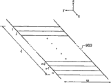
在某些实施例中,可以提供扫描器,该扫描器可操作为扫描跨所述读取体的一条,所述条被划分为多个目标区域,每个所述区域被并行地采样。在某些这种实施例中,单个公共光学系统可以用相同的数值孔径捕捉与每个目标区域有关的光,从而确保等同地处理所有捕捉的点。In some embodiments, a scanner may be provided operable to scan a strip across said read volume, said strip being divided into a plurality of target regions, each said region being sampled in parallel. In some such embodiments, a single common optical system can capture the light associated with each target region with the same numerical aperture, ensuring that all captured points are processed equally.
在某些实施例中,通过提供用于使得相干光束在所述读取体上移动的光栅化系统,来确保数据点中的不同的点与来自所述读取体的不同部分的散射有关。该光栅化系统可以利用可移动反射镜和/或可移动棱镜来反射和/或折射光束。另选地,可以提供驱动系统,使得光束和表面彼此相对地移动。另选地,在低成本的读取器中所述驱动可以是手动的。例如,操作者可以通过穿过静态光束移动其上安装有所述物品的托架(carriage),在所述读取体上扫描所述光束。可以提供聚焦设备,用于将所述相干光束聚焦到所述读取体内。该聚焦设备可以配置为将所述相干光束会聚到拉长的焦点,在该情况下,所述光栅化系统和/或驱动器优选地配置为相对于所述读取体沿所述拉长的焦点的主轴的横向方向移动所述相干光束。可以方便地使用柱透镜或等同的反射镜布置来提供拉长的焦点。In some embodiments, it is ensured that different ones of the data points are associated with scatter from different parts of the reading volume by providing a rasterization system for moving the coherent light beam over the reading volume. The rasterization system may utilize movable mirrors and/or movable prisms to reflect and/or refract light beams. Alternatively, a drive system may be provided such that the beam and surface move relative to each other. Alternatively, the actuation may be manual in low cost readers. For example, an operator may scan the beam across the reading body by moving a carriage on which the item is mounted across a static beam. A focusing device may be provided for focusing the coherent light beam into the reading volume. The focusing device may be configured to converge the coherent light beam to an elongated focal point, in which case the rasterization system and/or driver is preferably configured along the elongated focal point relative to the read volume Move the coherent beam in the lateral direction of the main axis. A cylindrical lens or an equivalent mirror arrangement may conveniently be used to provide an elongated focus.
在某些实施例中,所述预定最小值大于约0.1025。在其它实施例中,所述预定最小值大于约0.05。增大数值孔径会减小对反射信号中的高频分量的依赖性。In some embodiments, the predetermined minimum value is greater than about 0.1025. In other embodiments, the predetermined minimum value is greater than about 0.05. Increasing the numerical aperture reduces the dependence on high frequency components in the reflected signal.
在某些实施例中,所述装置可以具有0m到10m之间的读取范围。在其它实施例中,所述读取范围可在绝对范围和相对范围两者上或多或少地受限。当所述读取范围具有大的范围时,该装置还可以包括聚焦元件,该聚焦元件可操作为将相干光束聚焦在所述读取范围内的一定距离处。In some embodiments, the device may have a read range of between 0m and 10m. In other embodiments, the read range may be more or less limited both in absolute and relative range. When said read range has a large extent, the device may further comprise a focusing element operable to focus the coherent light beam at a distance within said read range.
在某些实施例中,所述光束引导元件可操作为将相干光束扫描(raster)过所述读取体。由此可以读取所述物品的比其焦点区域大得多的区域。In some embodiments, the beam directing element is operable to raster a coherent beam across the reading volume. A much larger area of the object than its focal area can thus be read.
在某些例子中,所述装置可以配置为读取来自移动穿过所述读取体的物品的反射信号。由此可以读取所述物品的比其焦点区域大得多的区域。In some examples, the device may be configured to read reflected signals from items moving across the reading volume. A much larger area of the object than its focal area can thus be read.
在某些例子中,可以提供单个光电检测器。该光电检测器可操作为检测沿着相干光束的路径反射回的信号。由此可以提供具有长的读取范围的紧凑的读取器装置。In some examples, a single photodetector may be provided. The photodetector is operable to detect signals reflected back along the path of the coherent light beam. A compact reader device with a long read range can thus be provided.
在其它例子中,可以提供多个光电检测器,其中每个光电检测器可操作为检测与所述相干光束的路径分别成不同角度反射的信号。由此,可以获得更难以欺骗的签名。In other examples, a plurality of photodetectors may be provided, wherein each photodetector is operable to detect signals reflected at respective different angles to the path of the coherent light beam. Thereby, a signature that is more difficult to spoof can be obtained.
在某些例子中,所述光束引导元件可操作为将相干光束引导到所述读取体上,使得该相干光束近乎垂直地入射到物品上。In some examples, the beam directing element is operable to direct a coherent beam onto the reading volume such that the coherent beam is approximately perpendicular to the article.
在某些例子中,所述处理器可操作为在所述签名中包含产生自从单个检测器通道接收的信号之间的比较的成分。所述比较可以包含互相关。In some examples, the processor is operable to include in the signature a component resulting from a comparison between signals received from a single detector channel. The comparison may involve cross-correlation.
在某些例子中,所述装置可以进一步包括以前记录的签名的数据库,其中该装置可操作为访问该数据库,并且执行比较以便确定所述数据库是否包含与置于所述读取体内的物品的签名的匹配。如果未发现匹配,则可以允许所述装置向所述数据库添加签名。In some examples, the device may further comprise a database of previously recorded signatures, wherein the device is operable to access the database and perform a comparison to determine whether the database contains signatures corresponding to items placed within the reader. Signed matches. If no match is found, the device may be allowed to add a signature to the database.
在某些例子中,所述处理器还可操作为通过数字化收集到的信号的傅立叶变换的幅值部分,来确定所述物品的缩略图签名。所述装置还可操作为将所述签名与其缩略图数字签名一起存储在数据库内。在所述签名与已经存储在所述数据库内的任何签名之间不存在匹配的条件下,可以将该签名与其缩略图签名一起存储在所述数据库内。In some examples, the processor is further operable to determine a thumbnail signature of the item by digitizing a Fourier transformed magnitude portion of the collected signal. The apparatus is further operable to store the signature in a database together with its thumbnail digital signature. On the condition that there is no match between the signature and any signature already stored in the database, the signature may be stored in the database together with its thumbnail signature.
在某些例子中,还可以提供以前记录的签名和它们的缩略图签名的数据库以及比较器,该比较器可操作为:搜索所述数据库以便通过在确定的缩略图签名和所述以前记录的缩略图签名之间进行比较,来寻找至少一个候选匹配;并且通过在所述确定的签名和所述至少一个以前记录的签名之间进行比较,来为任何候选匹配确定是否存在匹配。所述比较器还可操作为基于所述确定的签名和发现匹配的以前记录的签名之间的相似程度来为每个匹配确定置信级。所述比较器还可操作为将所述确定的签名分为邻接数据块,并且在每个块和所述存储的签名的相应块之间执行比较运算。所述比较器可另外操作为将来自每个块比较的比较结果的属性与所述块比较的期望属性进行比较,以便确定用于确定比较结果的补偿值;并且其中所述比较单元可进一步操作为使用所述补偿值调整所述确定的签名,来确定所述确定的签名和所述存储的签名之间的相似度结果。所述比较器还可操作为,将所述确定的签名的块和所述存储的签名的对应块之间的比较结果的实际互相关峰值位置与期望互相关峰值位置进行比较,以便确定用于确定比较结果的补偿值。所述比较器还可操作为通过为每个块比较求得对互相关峰值位置的最佳拟合函数来确定补偿值,所述最佳拟合函数表示距离期望互相关峰值位置的平均偏差。In some examples, there may also be provided a database of previously recorded signatures and their thumbnail signatures and a comparator operable to: search said database for comparison between a determined thumbnail signature and said previously recorded comparing thumbnail signatures to find at least one candidate match; and determining whether there is a match for any candidate match by comparing said determined signature and said at least one previously recorded signature. The comparator is further operable to determine a confidence level for each match based on a degree of similarity between the determined signature and a previously recorded signature for which a match was found. The comparator is further operable to divide the determined signature into contiguous blocks of data and perform a comparison operation between each block and a corresponding block of the stored signature. The comparator is additionally operable to compare an attribute of a comparison result from each block comparison with an expected attribute of the block comparison to determine an offset value for determining the comparison result; and wherein the comparison unit is further operable A similarity result between the determined signature and the stored signature is determined for adjusting the determined signature using the compensation value. The comparator is further operable to compare an actual cross-correlation peak position of a comparison between the determined signed block and the stored signed corresponding block with an expected cross-correlation peak position in order to determine the Determines the offset value for the comparison result. The comparator is further operable to determine the compensation value by comparing for each block a best-fit function to a cross-correlation peak position, the best-fit function representing an average deviation from an expected cross-correlation peak position.
在某些例子中,所述比较器可操作为,为每个比较的块计算相似度结果。所述比较器还可操作为,将至少一个预定块的相似度结果与预定相似度阈值进行比较。另外,所述比较器可操作为,在至少一个预定块的相似度结果低于所述预定相似度阈值的情况下,返回否定的比较结果,而不论签名整体的相似度结果如何。In some examples, the comparator is operable to compute a similarity result for each compared block. The comparator is further operable to compare the similarity result of at least one predetermined block with a predetermined similarity threshold. Additionally, the comparator is operable to return a negative comparison result in case the similarity result of at least one predetermined block is below said predetermined similarity threshold, regardless of the similarity result of the signature as a whole.
可以使用这种装置通过读取一连串的物品给数据库增加签名,以便验证物品的真实性和/或以便确定物品是否被篡改。Such a device may be used to add a signature to a database by reading a series of items in order to verify the authenticity of the items and/or to determine whether the items have been tampered with.
可以通过这样的方法验证物品,该方法包括使用上述的装置确定物品的签名,将如此确定的签名与物品的记录签名进行比较,以及根据签名和记录签名之间的相似度确定验证结果。The article may be authenticated by a method comprising determining the signature of the article using the apparatus described above, comparing the signature so determined with the recorded signature of the article, and determining the result of the verification based on the similarity between the signature and the recorded signature.
在某些实施例中,由于所述检测器设备包括布置并且配置为感测来自所述读取体的各个不同部分的散射的多个检测器通道,可以确保数据点中的不同数据点与来自所述读取体的不同部分的散射相关。这可以用定向检测器、利用光纤对信号的局部收集或其它方法实现。使用定向检测器或其它的信号局部收集,收集到的光不必被聚焦。可以通过熔合于检测器元件或以其他方式相对于检测器元件固定的聚焦透镜实现定向检测器。可以结合显微透镜使用光纤。In some embodiments, since the detector device comprises a plurality of detector channels arranged and configured to sense scatter from various parts of the read volume, it can be ensured that different ones of the data points correspond to those from Scatter correlation of different parts of the read volume. This can be accomplished with directional detectors, localized collection of signals using optical fibers, or other methods. Using directional detectors or other local collection of the signal, the collected light does not have to be focused. Directional detectors may be implemented by focusing lenses fused to or otherwise fixed relative to the detector elements. Fiber optics can be used in conjunction with microlenses.
读取器还包括用于容纳所述检测器设备的至少一部分的壳体,并且具有读取孔径,光束通过该读取孔径可被引导到所述读取体内。对于现场使用,设想读取器是基于具有读取孔径的壳体的整装(self-contained)单元。要由例如海关官员或贸易标准官员鉴别的物品可以是穿过所述读取孔径的光束的目标。可以用透明窗覆盖所述读取孔径以避免尘土进入光学元件。The reader also includes a housing for housing at least a portion of the detector device and has a reading aperture through which a light beam can be directed into the reading volume. For field use, the reader is envisaged as a self-contained unit based on a housing with a reading aperture. An item to be authenticated by eg a customs officer or a trading standards officer may be the target of a light beam passing through the reading aperture. The reading aperture can be covered with a transparent window to prevent dust from entering the optics.
其它形式的读取器可能更适合于生产线使用。例如,读取器还可以包括物品传送装置,用于移动物品通过相干光束,或更可能的是一连串类似的物品。在生产环境中,读取器可以是静态的,并且物品移动通过所述读取体。例如,香水的包装盒可以在设定高度处的传送装置上传递并横穿水平的激光束。Other forms of readers may be more suitable for production line use. For example, the reader may also include an item conveyor for moving the item through the coherent beam, or more likely a train of similar items. In a production environment, the reader may be static and items move across the reading body. For example, boxes of perfume can be passed on a conveyor at a set height and traversed by a horizontal laser beam.
在某些情况下,用于相对于所述读取体将给定形式的物品定位于固定位置的物理定位辅助设备是有用的。另选地,可以使用用于定位物品的预定扫描区域的模式匹配系统。应当理解,仅需要使用物品的一小部分(例如,包装或纸张项,或护照)来获得所述签名,尽管如果希望的话可以使用整个物品。从而,当为鉴别而重新读取物品时,测量物品的与初始测量相同的部分是重要的。为了帮助完成这个工作,某种形式的定位辅助设备可能是有用的。In some cases, a physical positioning aid for positioning an item of a given form in a fixed position relative to the reading volume is useful. Alternatively, a pattern matching system for locating a predetermined scan area of an item may be used. It should be appreciated that only a small portion of an item (eg, a package or item of paper, or a passport) needs to be used to obtain the signature, although the entire item could be used if desired. Thus, when re-reading an item for authentication, it is important to measure the same portion of the item as the initial measurement. To help with this, some form of positioning aid may be useful.
可以使用各种检测器设备。Various detector devices can be used.
可以制作其中检测器设备仅由单个检测器通道组成的读取器。其它实施例使用这样的检测器设备,该检测器设备包括成角度分布并且可操作为收集所述读取体的每个不同部分的一组数据点的一组检测器元件,优选地,由少量检测器元件构成的小组。当所述签名并有来自相同组的数据点之间的比较的成分时,提供了安全增强性。该比较可以方便地包含互相关。Readers can be made in which the detector device consists of only a single detector channel. Other embodiments use a detector device comprising a set of detector elements angularly distributed and operable to collect a set of data points for each different portion of the read volume, preferably consisting of a small number of A group of detector elements. Security enhancement is provided when the signature incorporates a component of comparison between data points from the same group. This comparison may conveniently involve cross-correlation.
虽然可以仅以一个检测器通道制作工作读取器,但是优选地有至少两个通道。这允许进行检测器信号间的互相关,这可用于与确定签名相关的信号处理。设想2到10个检测器通道将适用于大部分应用,而当前认为2到4个是装置简单性和安全性之间的最佳平衡。While it is possible to make a working reader with only one detector channel, it is preferred to have at least two channels. This allows cross-correlation between the detector signals, which can be used in signal processing related to determining the signature. It is envisaged that 2 to 10 detector channels will be suitable for most applications, while 2 to 4 are currently considered to be the best balance between device simplicity and safety.
已经发现使用从不同检测器获得的信号的互相关可以给出用于提高安全等级以及允许随着时间的流逝更易于可再现所述签名的有价值的数据。互相关的使用从科学的角度看多少有些奇怪,因为表面反射图案本质上是不相关的(来自图案中的相对点的信号除外)。换言之,对于散斑图案,只要不同的检测器未被以偏离激励(excitation)位置相等幅度的角布置在横穿该激励位置的公共平面内,则按照定义来自该不同检测器的信号之间的互相关为0。因此,使用互相关成分的值指示散射信号中的重要部分不是散斑。非散斑成分可被视为直接散射的结果,或是来自诸如纸纤维拧扭(twist)的复杂表面的漫散射成分。It has been found that using cross-correlation of the signals obtained from different detectors can give valuable data for increasing the level of security and allowing the signature to be more easily reproducible over time. The use of cross-correlation is somewhat strange from a scientific point of view, since surface reflection patterns are inherently uncorrelated (except for signals from opposite points in the pattern). In other words, for a speckle pattern, as long as the different detectors are not arranged in a common plane across the excitation position at angles of equal magnitude from the excitation position, by definition the difference between the signals from the different detectors is The cross-correlation is 0. Therefore, using the value of the cross-correlation component indicates that a significant portion of the scattered signal is not speckle. Non-speckle components can be seen as the result of direct scattering, or diffuse scattering components from complex surfaces such as paper fiber twists.
在所述签名中并入互相关分量还有益于提高安全性。这是由于即使可以使用高分辨率打印制作再现真品表面上的对比度变化的物品,也不可能匹配通过扫描真品获得的互相关系数。Incorporating a cross-correlation component in the signature is also beneficial for security. This is due to the fact that it is impossible to match the cross-correlation coefficients obtained by scanning the genuine article, even if an article that reproduces the contrast variation on the surface of the genuine article can be made using high-resolution printing.
因此将所述源安装为将相干光束引导到所述读取体上使得该相干光束近乎垂直地入射到物品上是有利的。近乎垂直地入射意指5、10或20度。另选地,光束可被引导为倾斜入射到物品上。在光束在物品上扫描的情况下,这具有不利影响。It is therefore advantageous to mount the source so as to direct the coherent beam onto the read volume such that the coherent beam hits the article nearly perpendicularly. Near normal incidence means 5, 10 or 20 degrees. Alternatively, the light beam may be directed obliquely incident on the item. This has a detrimental effect where the beam is scanned over the item.
还注意到在具体实施方式部分描述的读取器中,检测器设备被反射地布置以便检测从读取体散射回的辐射。然而,如果物品是透明的或半透明的,检测器可被透射地布置。It is also noted that in the readers described in the detailed description, the detector arrangement is reflectively arranged to detect radiation scattered back from the reading volume. However, if the item is transparent or translucent, the detector may be arranged transmissively.
本发明允许确定物品是否被篡改。如果在用于创建签名的扫描区域上粘附地接合诸如粘附带的透明膜,这是可能的。如果必须移去所述带以便篡改物品,例如,打开包装盒,可以选择粘性接合,使得将不可避免地修改下面的表面。从而即使使用类似的带重新密封所述盒,这也是可检测的。The invention allows determining whether an item has been tampered with. This is possible if a transparent film, such as an adhesive tape, is adhesively bonded over the scan area used to create the signature. If the strip must be removed in order to tamper with the item, for example, to open a box, an adhesive joint may be chosen so that modification of the underlying surface will inevitably be made. This is thus detectable even if the cartridge is resealed with a similar tape.
本发明提供了识别纸或卡板制作的物品的方法,该方法包括:将所述纸或卡板曝露于相干辐射;收集测量来自所述纸或卡板的内在结构的对所述相干辐射的散射的一组数据点;并且根据所述组数据点,确定所述物品的签名。The present invention provides a method of identifying an article made of paper or cardboard, the method comprising: exposing said paper or cardboard to coherent radiation; a scattered set of data points; and based on the set of data points, a signature of the item is determined.
内在结构意指物品由于其制造而固有地具有的结构,从而区别于专门出于安全目的提供的结构,诸如由并在物品内的标记或人造纤维给出的结构。Intrinsic structure means a structure inherent to an article as a result of its manufacture, as distinguished from structure provided exclusively for security purposes, such as that given by markings or artificial fibers incorporated within the article.
纸或卡板意指由木纸浆处理制成的任意物品。可以用涂覆或注入处理纸或卡板,或将其覆以诸如玻璃纸的透明材料。如果表面的长期稳定性是特别关心的,则例如可以用丙烯酸喷涂透明涂覆来处理纸张。Paper or cardboard means any article made from the processing of wood pulp. Paper or cardboard can be treated with coating or impregnation, or covered with a transparent material such as cellophane. If the long-term stability of the surface is of particular concern, the paper can be treated, for example, with an acrylic spray clear coat.
从下列例子看,本发明尤其适用于纸或卡板物品:The invention is especially applicable to paper or cardboard articles as seen from the following examples:
有价值的文档,例如股票、提货单、护照、政府间条约、法条、驾照、车辆性能证书、任何真实性的证书Valuable documents such as share certificates, bills of lading, passports, intergovernmental treaties, statutes, driver's licenses, vehicle certificates of performance, any certificate of authenticity
用于回溯或追踪目的的任何文档,例如,邮件系统的信封、用于执法跟踪的银行票据Any documents used for backtracking or tracing purposes, e.g., envelopes for mail systems, bank notes for law enforcement tracking
可销售产品的包装Packaging of salable products
设计者货品(例如,时髦品)上的商标标签Trademark labels on designer goods (e.g. fashion items)
化妆品、药品或其它产品的包装Packaging for cosmetics, pharmaceuticals or other products
CD和DVD,在盘本身上(例如接近中心处)或在外壳上。CDs and DVDs, either on the disc itself (eg near the center) or on the casing.
本发明还提供了识别由塑料制成的物品的方法,该方法包括:将所述塑料制品曝露于相干辐射;收集测量来自所述塑料制品的内在结构的对所述相干辐射的散射的一组数据点;并且根据所述组数据点,确定所述物品的签名。The present invention also provides a method of identifying an article made of plastic, the method comprising: exposing said plastic article to coherent radiation; data points; and based on the set of data points, determining a signature for the item.
如果所述塑料物品对于所述相干辐射不透明,则所述散射将来自于所述塑料物品的内在表面结构,而如果所述塑料物品是透明的,则所述散射可以产生自所述相干辐射碰到的所述物品的任意部分。If the plastic item is opaque to the coherent radiation, the scatter will come from the intrinsic surface structure of the plastic item, whereas if the plastic item is transparent, the scatter can arise from the coherent radiation colliding with the coherent radiation. to any part of said article.
根据下列的例子,可以认为本发明特别适用于塑料物品:According to the following examples, it can be considered that the invention is particularly applicable to plastic objects:
塑料包装,例如,药品的塑料包装Plastic packaging, e.g. for pharmaceuticals
ID卡,包括银行卡、职员ID卡、存储卡-包括ID卡尤其是银行或存储卡上的签名带ID cards, including bank cards, employee ID cards, memory cards - including ID cards, especially signature strips on bank or memory cards
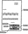
尤其有用的应用可以是在ID卡的签名带上扫描,即,在签名之后,从而用于真实性确认的数字签名对于该签名的卡是独特的,并且由人员的签名和下层带的表面结构的组合构成。A particularly useful application may be scanning on the signature tape of an ID card, i.e. after signing, whereby the digital signature used for authenticity confirmation is unique to the signed card and is determined by the person's signature and the surface structure of the underlying tape combination composition.
在带有人员的照片的ID物品(其可以是塑料的ID卡或其它材料的通行证,例如纸质护照)的情况下,作为是否发生了篡改的测试,使用读取器在ID卡的照片部分上扫描(与扫描封面或空白页分开)可能是有用的。这是因为如果使用涂层或粘性膜将照片附接于该ID物品上,伪造者必须将其移去以便将假的照片固定在该ID物品内。由于新的照片具有不同的表面结构,因此实施本发明的读取器可以识别出此类伪造。In the case of an ID item with a photo of a person (it could be a plastic ID card or a passport of other material, such as a paper passport), as a test of whether tampering has occurred, use the reader on the photo portion of the ID card Upscanning (separate from scanning covers or blank pages) may be useful. This is because if a coating or adhesive film is used to attach the photo to the ID item, the counterfeiter must remove it in order to secure the fake photo within the ID item. Since the new photo has a different surface structure, a reader embodying the invention can recognize such forgery.
希望本发明将可以识别任意其它材料类型,只要其具有适合的表面结构。具有在显微级别上非常平滑的表面的材料类型可能不适用,同样具有非常深和/或不稳定表面的不透明材料也不适用(例如,羊毛材料)。It is hoped that the present invention will recognize any other material type as long as it has a suitable surface structure. Material types with very smooth surfaces on a microscopic level may not be suitable, as are opaque materials with very deep and/or unstable surfaces (eg wool materials).
本发明还允许识别各种不同类型的物品,包括包装、文档和衣物。The invention also allows for the identification of various different types of items, including packaging, documents and clothing.
本发明提供了通过其包装识别产品的方法,该方法包括:将所述产品包装曝露于相干辐射;收集测量来自所述包装的内在结构的对所述相干辐射的散射的一组数据点;并且根据所述组数据点,确定所述产品的签名。The present invention provides a method of identifying a product by its packaging, the method comprising: exposing said product packaging to coherent radiation; collecting a set of data points measuring scattering of said coherent radiation from an intrinsic structure of said package; and From the set of data points, a signature of the product is determined.
包装的曝露于相干辐射的相关部分可由纸、卡板、塑料(例如,玻璃纸热缩包装)、金属或具有适合的内在表面和内部结构的其它材料制成。所述物品可被包含在包装内,并且可选地所述包装可被以防篡改方式密封。另选地,所述包装可以是所述物品的附属品,例如利用在不被明显破坏的情况下无法松开的连接器紧固的标签。这例如对于药品、化妆品和香水、以及航空器或者陆地或水上交通工具的备件尤其有用。The relevant portion of the package that is exposed to coherent radiation may be made of paper, cardboard, plastic (eg, cellophane shrink wrap), metal, or other material with suitable intrinsic surfaces and internal structures. The items may be contained within a package, and optionally the package may be sealed in a tamper-evident manner. Alternatively, the packaging may be an adjunct to the item, such as a label secured with a connector that cannot be released without being visibly damaged. This is especially useful, for example, for pharmaceuticals, cosmetics and perfumes, as well as spare parts for aircraft or land or water vehicles.
本发明提供了识别文档的方法,该方法包括:将所述文档曝露于相干辐射;收集测量来自所述文档的内在结构的对所述相干辐射的散射的一组数据点;并且根据所述组数据点,来确定所述文档的签名。The present invention provides a method of identifying a document comprising: exposing said document to coherent radiation; collecting a set of data points measuring the scattering of said coherent radiation from an intrinsic structure of said document; and based on said set data points to determine the signature of the document.
本发明还提供了通过固于其上的标签识别衣物或鞋的方法,该方法包括:将所述标签曝露于相干辐射;收集测量来自所述标签的内在结构的对所述相干辐射的散射的一组数据点;并且根据所述组数据点,来确定所述标签的签名。所述标签可以是通常的未修改的商标标签,例如,附于衣物或鞋的塑料、卡板。The present invention also provides a method of identifying clothing or shoes by a tag affixed thereto, the method comprising: exposing said tag to coherent radiation; a set of data points; and determining the tag's signature based on the set of data points. The label may be a normal unmodified brand label eg plastic, cardboard attached to clothing or shoes.
本发明还提供了识别诸如CD或DVD的盘的方法,该方法包括:将所述盘曝露于相干辐射;收集测量来自所述盘的对所述相干辐射的散射的一组数据点;并且根据所述组数据点,来确定所述盘的签名。The present invention also provides a method of identifying a disc, such as a CD or DVD, comprising: exposing said disc to coherent radiation; collecting a set of data points measuring the scatter of said coherent radiation from said disc; and according to The set of data points is used to determine the signature of the disc.
总之,在某些情况下,可从附属于可销售产品的某些东西(例如,其包装)获得签名,并且在其它情况下,从物体本身(例如,文档或可销售产品的表面结构)获得签名。本发明可以有许多实际应用,例如,控制灰色市场进口或伪造。对于这种应用,可由海关官员或贸易标准官员使用便携式读取器。In summary, in some cases a signature can be obtained from something attached to a salable product (e.g. its packaging) and in other cases from the object itself (e.g. a document or the surface structure of a salable product) sign. The invention may have many practical applications, for example, controlling gray market imports or counterfeiting. For this application, portable readers may be used by customs officers or trading standards officers.
在大多数应用中所述签名可被构想为数字签名。当前技术的数字签名的典型的大小在200比特到8k比特的范围内,当前优选地对于高安全性采用大小约为2k比特的数字签名。In most applications the signature can be thought of as a digital signature. Typical sizes of digital signatures of current technology are in the range of 200 bits to 8k bits, with digital signatures of about 2k bits size currently preferred for high security.
本发明的另一个方面提供以物品的内在结构的签名特性给该物品加标签的方法,该方法包括:通过应用任意上述识别方法获得签名;并且以根据机器可读的编码协议对所述签名编码的标签给所述物品做标记。Another aspect of the invention provides a method of tagging an item with a signature characteristic of its intrinsic structure, the method comprising: obtaining a signature by applying any of the identification methods described above; and encoding said signature in accordance with a machine-readable encoding protocol tag to mark the item in question.
优选地,使用不对称加密算法在所述标签中编码所述签名。例如,所述标签代表可由公钥/私钥加密系统中的公钥译码的密码。另选地,可以使用对称加密算法在所述标签中编码所述签名。Preferably, said signature is encoded in said tag using an asymmetric encryption algorithm. For example, the tag represents a cipher decipherable by a public key in a public/private key encryption system. Alternatively, the signature may be encoded in the tag using a symmetric encryption algorithm.
如果标签是以经过印刷工艺的墨水标签,则对于许多材料尤其是纸和卡板是极其方便的。It is extremely convenient for many materials, especially paper and cardboard, if the labels are printed ink labels.
所述标签可以是可视的,例如,条形码,或是不可视的,例如当物品是智能卡时,标签作为数据被包含在智能芯片内。The tag may be visible, such as a barcode, or invisible, such as when the item is a smart card, the tag is contained as data in the smart chip.
本发明还涉及根据上述添加标签的方法而添加了标签的物品。The invention also relates to an item tagged according to the above tagging method.
本发明的多个方面还提供了提高对包含极大量数字签名记录的数据库的搜索速度的方法。该方法包括不仅在数据库中存储扫描的签名的数字化表示,而且还存储所述签名的所谓的缩略图表示。这可以包括所述签名的子集和/或所述扫描的签名的傅立叶变换的一部分的数字化表示。当重新扫描物品时,处理重新扫描的数据以便根据重新扫描的数据形成缩略图。因此,在采用子集类型的缩略图时,取重新扫描的签名的相同的子集。然后使用该缩略图在数据库中搜索数据库中存储的签名的存储的缩略图。然后可以将由该缩略图搜索识别出的任意存储的签名与整个重新扫描的签名比较,以便确定是否存在匹配。由此,可以避免对数据库中每个签名的完整的搜索。Aspects of the invention also provide methods of increasing the speed of searches of databases containing extremely large numbers of digital signature records. The method consists in storing not only a digital representation of the scanned signature in a database, but also a so-called thumbnail representation of said signature. This may comprise a subset of the signature and/or a digitized representation of a portion of the Fourier transform of the scanned signature. When the item is rescanned, the rescanned data is processed to form a thumbnail from the rescanned data. Therefore, when using a subset type of thumbnail, the same subset of rescanned signatures is taken. The thumbnail is then used to search the database for stored thumbnails of signatures stored in the database. Any stored signatures identified by the thumbnail search can then be compared to the entire rescanned signature to determine if there is a match. Thereby, a complete search of every signature in the database can be avoided.
当使用基于傅立叶的缩略图时,对重新扫描的数据进行傅立叶变换。然后以极坐标,即幅值和相位(与以实部和虚部表示该傅立叶变换相对),表示该变换。使用幅值信息而不是相位信息进行搜索,可以将相位信息丢弃。即,在数据库中搜索新扫描的傅立叶变换幅值谱和作为每个数据库记录内的缩略图存储的傅立叶变换幅值谱间的匹配。如果存在该物品的匹配的数据库记录,将发现所述缩略图间的匹配,而不管新扫描和数据库扫描间的位移如何。具体地,不必为不同的假设位移重复该匹配,而这对于考虑原始扫描和重新扫描间的未知位移是必须的,该未知位移是由重新扫描时物品不可避免地在读取器上具有不同的相对位置引起的。When using Fourier-based thumbnails, perform a Fourier transform on the rescanned data. The transform is then represented in polar coordinates, ie, magnitude and phase (as opposed to representing the Fourier transform in real and imaginary parts). Searching using magnitude information instead of phase information discards the phase information. That is, the database is searched for a match between the newly scanned Fourier transform magnitude spectrum and the Fourier transform magnitude spectrum stored as a thumbnail image within each database record. If there is a matching database record for the item, a match between the thumbnails will be found regardless of the shift between the new scan and the database scan. In particular, the matching does not have to be repeated for different hypothetical displacements, which is necessary to account for unknown displacements between the original scan and the rescan caused by the item inevitably having a different caused by the relative position.
因此,与比较整个签名的简单的方法,即,与在实空间(与频率空间相对)内比较签名相比,以近似等于原始扫描和用于验证的重新扫描间的最大假设重定位误差除以每个数据的扫描长度(l/n)的因数加速了搜索。取决于有关的参数值,该因数典型地在10至50的范围内。由于需要将每个记录的傅立叶变换的幅值谱存储为缩略图,所以搜索速度的增大以略微增加的数据库大小为代价。Thus, compared to the simple method of comparing entire signatures, i.e., comparing signatures in real space (as opposed to frequency space), by approximately equal to the maximum hypothetical relocalization error between the original scan and the rescan used for verification divided by A factor of scan length (l/n) per data speeds up the search. This factor is typically in the range of 10 to 50, depending on the parameter value concerned. The increase in search speed comes at the expense of a slightly increased database size due to the need to store the Fourier-transformed magnitude spectrum of each record as a thumbnail.
该搜索方法由于下列原因起作用。进行了傅立叶变换的伪随机位序列在幅值谱中承载一些信息并且在相位谱中承载一些信息。然而任何位移仅影响相位谱,而不影响幅值谱。因此可以不需要知道任何位移地匹配幅值谱。虽然丢弃相位谱会丢失一些信息,但是剩余的信息足以获得与数据库的粗略的匹配。这允许将被在数据库中定位的目标的一个或多个推定(即,候选)匹配。然后可以适当地使用传统的实空间方法将这些推定匹配中的每一个与新扫描进行比较。This search method works for the following reasons. The Fourier transformed pseudorandom bit sequence carries some information in the magnitude spectrum and some information in the phase spectrum. However any displacement only affects the phase spectrum, not the magnitude spectrum. It is thus possible to match the magnitude spectrum without knowing any shifts. Although some information is lost by discarding the phase spectrum, the remaining information is sufficient to obtain a rough match to the database. This allows for one or more putative (ie, candidate) matches of targets to be located in the database. Each of these putative matches can then be compared to the new scan using conventional real-space methods as appropriate.
可以例如,在物品的制造时或在文档创建时执行扫描以获得并且存储所述物品的数字签名。在该情况下,所述数字签名与其缩略图数字签名一起存储在数据库中。为了避免重复的条目,优选地在数字签名和已经存储在数据库中的任何数字签名之间都不匹配的条件下,将数字签名和其缩略图数字签名一起存储在数据库内。附加地可以给物品添加机器可读的标记,诸如条形码,其对近似记录定位符编码,以便帮助在数据库中寻找数字签名。Scanning may be performed, for example, at the time of manufacture of an item or at the time of document creation to obtain and store a digital signature for said item. In this case, said digital signature is stored in the database together with its thumbnail digital signature. To avoid duplicate entries, a digital signature is stored in the database together with its thumbnail digital signature, preferably under the condition that there is no match between the digital signature and any digital signature already stored in the database. Items can additionally be inscribed with machine-readable indicia, such as barcodes, which encode approximate record locators to aid in finding digital signatures in databases.
还可以在以后进行物品验证时执行扫描。在该情况下,验证方法还将包括:提供以前记录的签名和它们的缩略图数字签名的数据库;通过执行确定的缩略图数字签名和以前记录的缩略图数字签名之间的比较,搜索该数据库以寻找至少一个候选匹配;并且通过执行确定的数字签名和至少一个以前记录的数字签名之间的比较,为任何的候选匹配确定是否存在匹配。附加地,针对每个匹配,可以基于确定的数字签名和已经发现具有匹配的以前记录的数字签名之间的相似度来确定置信级。这可用于呈现给用户。如果在物品上提供有近似记录定位符标记,则该验证方法将包括读取物品上的机器可读标记,以便获得所述近似记录定位符,并且使用该近似记录定位符在数据库中寻找至少一个候选匹配。Scanning can also be performed at a later date for item verification. In this case, the verification method will also include: providing a database of previously recorded signatures and their thumbnail digital signatures; searching this database by performing a comparison between the determined thumbnail digital signatures and the previously recorded thumbnail digital signatures to find at least one candidate match; and determining for any candidate match whether there is a match by performing a comparison between the determined digital signature and at least one previously recorded digital signature. Additionally, for each match, a confidence level may be determined based on a degree of similarity between the determined digital signature and previously recorded digital signatures that have been found to have matches. This can be used to present to the user. If an approximate record locator indicia is provided on the item, the verification method will include reading the machine-readable indicia on the item to obtain said approximate record locator, and using the approximate record locator to find in a database at least one Candidate match.
在用于丰富数据库的装置,例如,由商标所有人或政府当局使用的装置中,数据获取和处理模块还可操作为将数字签名与其缩略图数字签名一起存储在数据库中。为了避免重复的条目,这可以用在数字签名和已经存储在数据库内的任何数字签名之间都没有匹配的条件下。In an apparatus for enriching a database, eg, an apparatus used by a trademark owner or a government authority, the data acquisition and processing module is also operable to store the digital signature in the database together with its thumbnail digital signature. To avoid duplicate entries, this can be used under the condition that there is no match between the digital signature and any digital signature already stored in the database.
在用于验证物品的真实性的装置(例如,现场使用的读取器)中,该装置还将包括:以前记录的签名和它们的缩略图数字签名的数据库;和搜索工具,该搜索工具可操作为(i)通过执行确定的缩略图数字签名和以前记录的缩略图数字签名之间的比较,搜索数据库以便寻找至少一个候选匹配;和(ii)通过执行确定的数字签名和所述至少一个以前记录的数字签名之间的比较,针对任何候选匹配确定是否存在匹配。该搜索工具还可操作为,基于确定的数字签名和发现具有匹配的以前记录的数字签名之间的相似度,为每个匹配确定置信级。In a device for verifying the authenticity of an item (e.g., a reader for use in the field), the device will also include: a database of previously recorded signatures and their thumbnail digital signatures; and a search tool that can The operation is (i) searching the database for at least one candidate match by performing a comparison between the determined thumbnail digital signature and previously recorded thumbnail digital signatures; and (ii) by performing the determined digital signature and the at least one A comparison between previously recorded digital signatures to determine, for any candidate matches, whether there is a match. The search tool is also operable to determine a confidence level for each match based on a similarity between the determined digital signature and a previously recorded digital signature found to have a match.
还可以提供通常驻留在诸如服务器或其它系统的承载介质上的数据库,该数据库包括多个记录,每个记录包括:通过数字化从物品获得的一组数据点而获得的该物品的数字签名;和通过选择所述签名的比特的子集或是数字化该组数据点的傅立叶变换的幅值部分而获得的该物品的缩略图数字签名。还可以提供搜索工具,该搜索工具可操作为:通过在输入的缩略图数字签名和保持在上述数据库内的缩略图数字签名之间进行比较,在该数据库中搜索候选匹配。该搜索工具还可操作为通过在输入的数字签名和保持在候选匹配的记录内的数字签名之间进行比较,为任意候选匹配确定是否存在匹配。尤其对于大型数据库,该搜索工具可操作为使用近似记录定位符在数据库中搜索候选匹配。There may also be provided a database, typically residing on a carrier medium such as a server or other system, the database comprising a plurality of records, each record comprising: a digital signature of an item obtained by digitizing a set of data points obtained from the item; and a thumbnail digital signature of the item obtained by selecting a subset of the bits of said signature or digitizing the magnitude portion of the Fourier transform of the set of data points. There may also be provided a search tool operable to search for candidate matches in the database by comparing the input thumbnail digital signature with thumbnail digital signatures maintained in the above-mentioned database. The search tool is also operable to determine for any candidate match whether there is a match by comparing the entered digital signature with the digital signature maintained within the record of the candidate match. Especially for large databases, the search tool is operable to search the database for candidate matches using approximate record locators.
应当理解,该数据库可以远离所述系统或与系统集成在一起,或甚至是分布式的。It should be understood that the database may be remote or integrated with the system, or even distributed.
数据库可以是构成所述读取器装置的一部分的海量存储设备的一部分,或可位于远程位置并可被所述读取器通过电信链路访问。该电信链路可采用任意常见形式,包括无线和固定链路,并且还可通过因特网获得。数据获取和处理模块至少在某些操作模式下可操作为,如果未发现匹配,则允许将所述签名添加到数据库内。出于显而易见的原因,通常仅允许获得授权的人员拥有这种便捷。The database may be part of a mass storage device forming part of the reader arrangement, or may be located at a remote location and accessible by the reader via a telecommunications link. This telecommunication link can take any common form, including wireless and fixed links, and is also available through the Internet. The data acquisition and processing module is operable, at least in certain modes of operation, to allow said signature to be added to the database if no match is found. For obvious reasons, this convenience is usually only allowed to authorized personnel.
当使用数据库时,除了存储签名之外,将数据库内的签名与关于物品的其它信息(例如,文档的扫描拷贝,护照持有者的照片,关于产品的制造地点和时间的细节,或关于可销售货物的预期销售目的地的细节(例如,为了跟踪灰色进口品))相关联也可能是有用的。When using a database, in addition to storing the signature, the signature within the database is linked with other information about the item (for example, a scanned copy of a document, a photograph of the passport holder, details about where and when the product was manufactured, or information about the available It may also be useful to associate details of the intended sales destination of the sold goods (for example, to track gray imports).
可以使用上述的读取器装置,以便通过读取例如生产线上的一连串物品以签名丰富数据库,和/或以便随后在例如现场使用中验证物品的真实性。A reader device as described above may be used in order to enrich a database for signatures by reading a series of items, for example on a production line, and/or to verify the authenticity of the items later in use, for example in the field.
从一些方面看,本发明提供了一种物品识别方法,该方法包括:如上所述地基于物品的内在特性从该物品确定签名;和将确定的签名和存储的签名进行比较。该方法还包括将确定的签名分为多个邻接数据块,并且在每个块和存储的签名的相应块之间进行比较。因此可以实现较高粒度级的物品验证。Viewed in some aspects, the present invention provides a method of item identification, the method comprising: determining a signature from an item based on an intrinsic characteristic of the item as described above; and comparing the determined signature with a stored signature. The method also includes dividing the determined signature into a plurality of contiguous data blocks and performing a comparison between each block and a corresponding block of the stored signature. Item verification at a higher granularity level can thus be achieved.
在某些实施例中,该方法还可以包括:将来自每个块比较的比较结果的属性和该块比较的期望属性进行比较,以便确定在确定比较结果时使用的补偿值。该方法还可以包括:使用该补偿值调整确定的签名,来确定所述确定的签名和存储的签名之间的相似度结果。由此,可以成功地识别由拉伸或收缩受损的物品。另外,可以提供非线性签名确定而不损失识别准确性。因此,可以补偿签名产生步骤中的各种物理对准偏差,以便允许实现正确的比较结果。In some embodiments, the method may also include comparing the attributes of the comparison result from each block comparison to the expected attribute of the block comparison to determine the compensation value used in determining the comparison result. The method may further include: adjusting the determined signature using the compensation value to determine a similarity result between the determined signature and the stored signature. Articles damaged by stretching or shrinkage can thus be successfully identified. Additionally, non-linear signature determination can be provided without loss of recognition accuracy. Thus, various physical alignment deviations in the signature generation step can be compensated in order to allow correct comparison results to be achieved.
在某些实施例中,来自每个块比较的比较结果的属性和该块比较的期望属性的比较包括将所述确定的签名的块和所述存储的签名的对应块之间的比较结果的实际互相关峰值位置与期望互相关峰值位置进行比较,以便确定用于确定比较结果的补偿值。由此,可以使用该期望结果来解决扫描过程中物品的物理对准偏差。In some embodiments, comparing the properties of the comparison result from each block comparison with the expected property of that block comparison includes comparing the comparison result between said determined signed block and said stored signed corresponding block The actual cross-correlation peak position is compared with the expected cross-correlation peak position to determine an offset value for determining the result of the comparison. Thus, this desired result can be used to account for deviations in the physical alignment of the item during scanning.
在某些实施例中,确定补偿值包括为每个块比较求得对互相关峰值位置的最佳拟合函数,该最佳拟合函数表示距离期望互相关峰值位置的平均偏差。因此,距离期望位置的平均偏差可用于所述补偿。该平均偏差可以用许多方法测量,并且可以得到最佳拟合函数,该最佳拟合函数可以是可包括直线函数、指数函数、三角函数和x2函数的各种函数之一。In some embodiments, determining the compensation value includes finding, for each block comparison, a best-fit function to a cross-correlation peak location, the best-fit function representing an average deviation from an expected cross-correlation peak location. Thus, the average deviation from the desired position can be used for the compensation. This average deviation can be measured in a number of ways and a best fit function can be obtained, which can be one of a variety of functions which can include linear, exponential, trigonometric and x2 functions.
在某些实施例中,该方法还包括将确定的签名与多个存储的签名进行比较。可以发现确定的签名和多个存储的签名间的最接近匹配结果。另外,如果已经针对确定的签名确定相似度结果低于每个存储的签名的预定阈值,则可以发现不匹配结果。因此,可将项目与项目签名的数据库进行比较,以便确定该项目是否是该数据库的成员。这可用于确定各种物品(例如,产品、价值转让标记、价值转让授权标记、权利标记和访问标记)的真实性。In some embodiments, the method further includes comparing the determined signature to a plurality of stored signatures. The closest match between a certain signature and a number of stored signatures can be found. Additionally, a non-matching result may be found if the similarity result has been determined for the determined signature to be below a predetermined threshold per stored signature. Accordingly, an item may be compared to a database of item signatures in order to determine whether the item is a member of the database. This can be used to determine the authenticity of various items (eg, products, value transfer tokens, value transfer authorization tokens, entitlement tokens, and access tokens).
在某些实施例中,该方法还可以包括为每个比较块计算相似度结果。在某些实施例中,该方法还可以包括将至少一个预定块的相似度结果和预定相似度阈值进行比较,并且不论签名整体的相似度结果如何,在所述至少一个预定块的相似度结果低于预定相似度阈值时返回否定的比较结果。因此可以识别物品的重要部分,并且要求针对该重要部分的物品真实性验证以及签名整体的肯定的匹配。In some embodiments, the method may also include calculating a similarity result for each comparison block. In some embodiments, the method may further include comparing the similarity result of at least one predetermined block with a predetermined similarity threshold, and regardless of the similarity result of the signature as a whole, the similarity result of the at least one predetermined block Returns a negative comparison result below a predetermined similarity threshold. A significant part of the item can thus be identified and a verification of the authenticity of the item for this significant part and a positive match of the signature as a whole is required.
从第二个方面看,本发明提供了一种用于标识物品的系统。该系统可以包括:签名确定单元,其可操作为基于物品的内在特性确定来自物品的签名;以及比较单元,其可操作为将确定的签名和存储的签名进行比较。该比较单元可操作为将确定的签名分为多个邻接数据块,并且执行每个块和存储的签名的相应块之间的比较。因此,可以实现对物品签名的高粒度分析。Viewed from a second aspect, the invention provides a system for identifying items. The system may include: a signature determination unit operable to determine a signature from the item based on an intrinsic characteristic of the item; and a comparison unit operable to compare the determined signature with a stored signature. The comparison unit is operable to divide the determined signature into a plurality of contiguous data blocks and perform a comparison between each block and a corresponding block of the stored signature. Thus, highly granular analysis of item signatures can be achieved.
在某些实施例中,该比较单元还可操作为将来自每个块比较的比较结果的属性和该块比较的期望属性进行比较,以便确定在确定比较结果时使用的补偿值。该比较单元还可操作为使用该补偿值调整所述确定的签名,以确定所述确定的签名和存储的签名之间的相似度结果。因此,可以成功地识别由拉伸或收缩受损的物品。另外,可以提供非线性签名确定而不损失识别准确性。因此,可以补偿签名产生步骤中的各种物理对准偏差,以便允许实现正确的比较结果。In some embodiments, the comparison unit is further operable to compare the attribute of the comparison result from each block comparison with the expected attribute of the block comparison in order to determine the compensation value used in determining the comparison result. The comparison unit is further operable to adjust the determined signature using the compensation value to determine a similarity result between the determined signature and the stored signature. Thus, items damaged by stretching or shrinkage can be successfully identified. Additionally, non-linear signature determination can be provided without loss of recognition accuracy. Thus, various physical alignment deviations in the signature generation step can be compensated in order to allow correct comparison results to be achieved.
在某些实施例中,该比较单元可操作为针对每个比较块计算相似度结果。该比较单元还可操作为将至少一个预定块的相似度结果和预定相似度阈值进行比较,并且不论签名整体的相似度结果如何,在至少一个预定块的相似度结果低于预定相似度阈值的情况下返回否定的比较结果。因此可以识别物品的重要部分,并且对其进行比物品的其它区域更高等级的仔细检查。In some embodiments, the comparison unit is operable to calculate a similarity result for each comparison block. The comparison unit is also operable to compare the similarity result of at least one predetermined block with a predetermined similarity threshold, and irrespective of the similarity result of the signature as a whole, at the time when the similarity result of at least one predetermined block is lower than the predetermined similarity threshold case returns a negative comparison result. Important parts of the item can thus be identified and subjected to a higher level of scrutiny than other areas of the item.
从下面详细的描述中将明了本发明的其它方面和实施例。Other aspects and embodiments of the invention will be apparent from the following detailed description.
附图说明Description of drawings
为了更好地理解本发明,并且示出如何实现本发明,作为例子参考附图,在附图中:For a better understanding of the invention, and to show how it can be practiced, reference is made by way of example to the accompanying drawings, in which:
图1是从表面反射的聚焦的相干光的示意图;Figure 1 is a schematic diagram of focused coherent light reflected from a surface;
图2是用于检测从表面反射的聚焦的相干光的检测器设备的示意图;Figure 2 is a schematic diagram of a detector device for detecting focused coherent light reflected from a surface;
图3是关于目标倾斜对检测器结果的影响的图示;Figure 3 is a graphical representation of the effect of target tilt on detector results;
图4是示出了检测器数值孔径对检测器结果的影响的示意曲线图;Figure 4 is a schematic graph showing the effect of detector numerical aperture on detector results;
图5是示出了检测器数值孔径对检测器结果的影响的经验曲线图;Figure 5 is an empirical graph showing the effect of detector numerical aperture on detector results;
图6A和图6B示出了平移错位对检测器结果的影响;Figures 6A and 6B illustrate the effect of translational misalignment on detector results;
图7示出了检测器装置的示意图;Figure 7 shows a schematic diagram of a detector arrangement;
图8示出了检测器装置的示意图;Figure 8 shows a schematic diagram of a detector arrangement;
图9示出了示例扫描器装置的示意截面图;Figure 9 shows a schematic cross-sectional view of an example scanner device;
图10示出了相干光束在目标上的入射模式的示意图;Figure 10 shows a schematic diagram of the incident mode of a coherent beam on a target;
图11示出了扩束器的示意立体图;Figure 11 shows a schematic perspective view of a beam expander;
图12示出了检测器装置光学组件的示意立体图;Figure 12 shows a schematic perspective view of the optical assembly of the detector device;
图13示出了光通过图12的组件的示意光线跟踪示图;Figure 13 shows a schematic ray tracing diagram of light passing through the components of Figure 12;
图14示出了光通过图12的组件的示意光线跟踪示图;Figure 14 shows a schematic ray tracing diagram of light passing through the components of Figure 12;
图15示出了图12的组件的示意图;Figure 15 shows a schematic diagram of the assembly of Figure 12;
图16示出了示例的检测器信号电平输出;Figure 16 shows an example detector signal level output;
图17示出了检测器装置外壳的示意图;Figure 17 shows a schematic diagram of the detector device housing;
图18示出了工艺线扫描器装置的示意立体图;Figure 18 shows a schematic perspective view of a process line scanner device;
图19示出了示例的距离读取扫描器装置;Figure 19 shows an exemplary range-reading scanner arrangement;
图20A示出了旋转扫描器装置的示意图;Figure 20A shows a schematic diagram of a rotating scanner device;
图20B和图20C示出了图20A的装置的示意扫描路径;Figures 20B and 20C show schematic scan paths for the device of Figure 20A;
图21示出了检测器数据收集电路的示意电路图;Figure 21 shows a schematic circuit diagram of a detector data collection circuit;
图22示出了图21的一部分电路的示意电路图;Fig. 22 shows a schematic circuit diagram of a part of the circuit of Fig. 21;
图23示出了示例扫描器装置的示意截面图;Figure 23 shows a schematic cross-sectional view of an example scanner device;
图24示出了光栅光束的入射路径的示意图;Figure 24 shows a schematic diagram of the incident path of a grating beam;
图25示出了光栅光束的入射路径的示意图;Figure 25 shows a schematic diagram of the incident path of a grating beam;
图26示出了图23的扫描器装置的示意截面图;Figure 26 shows a schematic cross-sectional view of the scanner device of Figure 23;
图27示出了示例扫描器装置的示意截面图;Figure 27 shows a schematic cross-sectional view of an example scanner device;
图28示出了示例扫描器装置的示意截面图;Figure 28 shows a schematic cross-sectional view of an example scanner device;
图29示出了扫描线型入射路径的示意图;Figure 29 shows a schematic diagram of a scanning line incident path;
图30示出了示例扫描线型扫描器装置的示意图;Figure 30 shows a schematic diagram of an example scanline scanner arrangement;
图31示出了用于从单个光源创建多扫描线系统的光学布置的示意图;Figure 31 shows a schematic diagram of an optical arrangement for creating a multi-scanline system from a single light source;
图32示出了纸张上的点的经构造的伪图像;Figure 32 shows a constructed pseudo-image of points on paper;
图33示出了图32的纸张上的逆散斑图像;Figure 33 shows the inverse speckle image on the paper of Figure 32;
图34示出了印刷装置中的示例扫描器装置的示意截面图;Figure 34 shows a schematic cross-sectional view of an example scanner device in a printing device;
图35示出了复印设备的扫描器装置的示例;Figure 35 shows an example of a scanner device of a copying apparatus;
图36示出了图35的装置的功能部件的示意框图;Figure 36 shows a schematic block diagram of the functional components of the device of Figure 35;
图37是具有覆盖大约0.5×0.2mm区域的图像的纸表面的显微图像;Figure 37 is a microscopic image of a paper surface with an image covering an area of approximately 0.5 x 0.2 mm;
图38是具有覆盖大约0.02×0.02mm区域的图像的塑料表面的显微图像;Figure 38 is a microscopic image of a plastic surface with an image covering an area of approximately 0.02 x 0.02 mm;
图39A示出了以编码器信号线性化并且进行了幅值平均之后的来自单个光电检测器的光电检测器数据;Figure 39A shows photodetector data from a single photodetector after linearization with the encoder signal and amplitude averaging;
图39B示出了根据平均电平数字化之后的图39A的数据;Figure 39B shows the data of Figure 39A after digitization according to the average level;
图40是示出了如何从扫描产生物品的签名的流程图;Figure 40 is a flowchart showing how a signature for an item is generated from a scan;
图41是示出了如何相对于签名数据库验证从扫描获得的物品的签名的流程图;Figure 41 is a flow diagram illustrating how the signature of an item obtained from a scan is verified against a database of signatures;
图42A是示出了可如何计算多个自由度的曲线图;Figure 42A is a graph showing how multiple degrees of freedom can be calculated;
图42B是示出了可如何计算多个自由度的曲线图;Figure 42B is a graph showing how multiple degrees of freedom can be calculated;
图43是示出了如何为了验证的目的扫描文档以及将结果呈现给用户的整个处理的流程图;Figure 43 is a flowchart showing the overall process of how documents are scanned for verification purposes and the results presented to the user;
图44A是示出了可以如何改变图40的验证处理以便解决扫描中的非理想化问题的流程图;FIG. 44A is a flow diagram illustrating how the verification process of FIG. 40 may be changed in order to account for non-idealities in the scan;
图44B是示出了可以如何改变图40的验证处理以便解决扫描中的非理想化问题的另一个例子的流程图;FIG. 44B is a flowchart illustrating another example of how the verification process of FIG. 40 may be changed to account for non-idealities in the scan;
图45A示出了从扫描收集的互相关数据的例子;Figure 45A shows an example of cross-correlation data collected from scans;
图45B示出了在扫描物品被扭曲的情况下,从扫描收集的互相关数据的例子;Figure 45B shows an example of cross-correlation data collected from scans where the scanned item is distorted;
图45C示出了在以非线性速度扫描被扫描物品的情况下从扫描收集的互相关数据的例子;Figure 45C shows an example of cross-correlation data collected from scans where the scanned item is scanned at a non-linear velocity;
图46示出了示例扫描器装置的示意截面图;Figure 46 shows a schematic cross-sectional view of an example scanner device;
图47示出了示例扫描器装置的示意截面图;Figure 47 shows a schematic cross-sectional view of an example scanner device;
图48是带有条形码标签的ID卡的示意平面图,该条形码标签对根据内在测量表面特性获得的数字签名编码;Figure 48 is a schematic plan view of an ID card with a barcode label encoding a digital signature obtained from intrinsically measured surface properties;
图49是带有芯片的ID卡的示意平面图,该芯片带有对根据内在测量表面特性获得的数字签名编码的数据;以及Figure 49 is a schematic plan view of an ID card with a chip carrying data encoding a digital signature obtained from intrinsically measured surface properties; and
图50是带有两个条形码标签的担保文档的示意平面图,所述两个条形码标签对根据内在测量表面特性获得的数字签名编码;Figure 50 is a schematic plan view of a warranty document with two barcode labels encoding a digital signature derived from intrinsically measured surface properties;
图51A到图51D示出了用于确定相对于目标的速度的内扫描器系统;51A-51D illustrate an inner scanner system for determining velocity relative to a target;
图52示出了安全密封的示意图;Figure 52 shows a schematic diagram of a safety seal;
图53A到图53E示出了使用光管的扫描器装置检测器光学系统;Figures 53A to 53E illustrate scanner device detector optics using light pipes;
图54A到图54C示出了使用光纤光导的扫描器装置检测器光学系统;Figures 54A to 54C illustrate scanner device detector optics using fiber optic light guides;
图55示意地示出了用于存储记录签名的数据库结构;Figure 55 schematically shows a database structure for storing record signatures;
图56示意地示出了用于存储记录签名的数据库结构;Figure 56 schematically shows a database structure for storing record signatures;
虽然本发明能有各种修改和替换形式,但在附图中以示例的方式示出了特定的实施例,并且在此处对其进行详细描述。然而应当理解,这些附图和详细说明不旨在将本发明限制于所公开的特定形式,相反,本发明要覆盖落在所附权利要求所限定的本发明的精神和范围内的所有修改、等同物和替换物。While the invention is capable of various modifications and alternative forms, specific embodiments are shown by way of example in the drawings and described in detail herein. It should be understood, however, that the drawings and detailed description are not intended to limit the invention to the particular forms disclosed, but on the contrary, the invention is to cover all modifications, Equivalents and Alternatives.
具体实施方式Detailed ways
图1是从表面反射的聚焦的相干光的示意图。如图所示,相干光束发生器10产生被引导到物品15的表面14上的相干光束12。相干光束相干光束发生器10可以包括激光光源(未示出)和用于将激光束聚焦到所述表面上的聚焦元件(未示出)。Figure 1 is a schematic diagram of focused coherent light reflected from a surface. As shown, a
聚焦的相干光束12在位置16触及该表面,从位置16处产生示出为光束18的反射。本领域的读者将会理解示出的光束18仅是例示性的,实际上在垂直于表面14的平面的所有平面内将有无数光束从位置16反射。当从距离位置16恒定距离d处观看时,可认为该反射光形成反射光半球。在图1的二维图像中可被认为是具有半径d的半圆。Focused
该反射光包含关于位置16处的表面14的信息。该信息可以包括关于表面14的显微级的表面粗糙度的信息。该反射光以反射光观测图中的特征波长的形式承载该信息。通过检测这些波长特征,可以基于位置16处的表面14的表面结构得出指纹或签名。通过测量表面14的若干位置处的反射,该指纹或签名可以基于对该表面的大规模采样,从而使得在日后再次读取该表面后,易于将来自后来读取的签名与来自原始读取的签名进行匹配。This reflected light contains information about the
如图1所示,反射光18包括两个主要角波长或角频率区域的信息。高角频率(短波长)信息是传统上被称为散斑并且以小波长线20表示的信息。该高角频率分量典型地具有大约0.5度的角周期。以长波长线22表示低角频率(长波长)信息。该低角频率分量典型地具有大约15度的角周期。As shown in FIG. 1 , reflected
图2示出了用于检测从表面反射的聚焦相干光的检测器设备的示意图。如图2所示,聚焦相干光束相干光束发生器10输出在位置16入射到物品15的表面14上的聚焦相干光束12。这使得要从位置16反射其中以波长扰动的形式承载表面信息的反射光18。Figure 2 shows a schematic diagram of a detector device for detecting focused coherent light reflected from a surface. As shown in FIG. 2 , a focused coherent beam
在图2中,仅在与光电检测器24的角度位置相对应的位置处示出反射光束18。出于解释容易和附图清楚的目的,在图2中示出了两个光电检测器。然而,系统正确工作仅需要一个光电检测器。另选地,可以提供更多个光电检测器,例如,在一个例子中,可以提供4个光电检测器。每个光电检测器收集立体角θn上的反射光。在当前的讨论中假设每个光电检测器收集正方形或圆形区域上的光。光收集的立体角可在不同的光电检测器24间改变。每个光电检测器24测量距离表面14具有最小角度θr的反射光。因此,由给定光电检测器24检测到的光包括相对于表面14的角度在θr到θr+θn之间的反射光束。如下面将更详细描述的,使得抗欺骗系统具有以最大可能角度分开的检测器通道是有利的。这导致角度θr尽可能的小。In FIG. 2 , the reflected
应当理解,光电检测器24检测反射光的立体角还可以被表示为数值孔径(NA),其中:It should be understood that the solid angle over which

其中
NA=sin(θn/2)NA=sin(θ n /2)
因此,具有大数值孔径的光电检测器将具有收集更大量光(即,更多光子)的潜力,但是这具有平均更多反射信息(散斑)的效果,使得所有捕捉信息散斑的总和较弱。然而,长角波长分量比短角波长(传统的散斑)分量更少地受到该平均影响,从而这具有提高长波长反射信号相对于短波长反射信号的比例的效果。Therefore, a photodetector with a large numerical aperture will have the potential to collect a greater amount of light (i.e., more photons), but this has the effect of averaging more reflected information (speckle), making the sum of all captured information speckles smaller. weak. However, the long angular wavelength components are less affected by this averaging than the short angular wavelength (traditional speckle) components, so this has the effect of increasing the proportion of long to short wavelength reflected signals.
虽然图1和图2示出了聚焦相干光束12垂直地入射到表面14,但是应当理解,实际上可能难以确保完全垂直入射。在提供低成本读取器的情况下尤为如此,其中由具有很少训练或未训练的用户执行定位,或物品的定位不受用户控制,例如在包括诸如传输物品的传送器的商业处理环境,以及从读取器到物品的距离使得读取器和物品间没有物理接触的任何环境中。因此,实际上极有可能入射的聚焦相干光束不是理想地垂直照射到物品。While FIGS. 1 and 2 show the focused
已经发现入射角度仅改变几分之一度就可以对来自表面的反射散斑图案具有显著影响。例如,图3A示出了一张普通白纸(例如,可用于传统的打印机或复印机的普通白纸)的常规散斑图案的图像。图3B示出了同一纸张在相同照明条件下被相对于其在图3A的图像中的位置倾斜0.06度时的散斑图案的图像。任何观看者可以立即明白作为该表面上的这个极小的角度扰动的结果,散斑图案已明显地改变了。因此,如果根据来自这两个图像的各个数据集合中的每一个产生签名,则这两个签名间的互相关将提供比扫描同一目标而产生的两个签名间的互相关通常所期望的结果低得多的结果。It has been found that changing the angle of incidence by only a fraction of a degree can have a significant effect on the reflected speckle pattern from a surface. For example, FIG. 3A shows an image of a conventional speckle pattern of a piece of plain white paper (eg, plain white paper that may be used in a conventional printer or copier). Figure 3B shows an image of the speckle pattern of the same paper when it is tilted by 0.06 degrees relative to its position in the image of Figure 3A under the same lighting conditions. Any viewer can immediately see that the speckle pattern has changed visibly as a result of this tiny angular perturbation on the surface. Therefore, if a signature is generated from each of the respective data sets from the two images, the cross-correlation between the two signatures will provide a more favorable result than the cross-correlation between the two signatures generated by scanning the same target would normally expect. much lower results.
已经发现,当以小的量反复增加该角度并且进行测量且在每个新测量和基线原始测量(具有零偏移角)间计算互相关时,互相关结果随着偏移角开始增加而迅速下降。然而,当角度增加超过某个点时,互相关结果饱和,使得互相关结果相对于偏移角的曲线稳定在大致恒定的互相关值处。这个效果是由反射光中的低频分量提供的。当入射角中的扰动增加时,反射光的高频散斑分量迅速去耦。然而,一旦角度增加了某个量,传统散斑(高频)分量的影响变得低于低频分量的影响。因此,一旦低频分量成为互相关结果中最重要的因素,该分量(其更具入射角容限)使得互相关结果饱和,尽管会进一步增大入射角扰动。It has been found that when the angle is repeatedly increased by small amounts and measurements are taken and the cross-correlation is computed between each new measurement and the baseline raw measurement (with zero offset angle), the cross-correlation results rapidly increase as the offset angle begins to increase decline. However, when the angle increases beyond a certain point, the cross-correlation result saturates such that the curve of the cross-correlation result versus offset angle stabilizes at an approximately constant cross-correlation value. This effect is provided by low frequency components in the reflected light. The high-frequency speckle components of the reflected light are rapidly decoupled when the perturbation in the incident angle increases. However, once the angle is increased by a certain amount, the influence of the conventional speckle (high frequency) component becomes lower than that of the low frequency component. Therefore, once the low-frequency component becomes the most important factor in the cross-correlation result, this component (which is more incident angle tolerant) saturates the cross-correlation result, although it will further increase the incident angle perturbation.
图4示出了这种现象,其中示出了在光电检测器的各种不同数值孔径下互相关结果相对于偏移角的示意曲线图。如图4所示,在0.06的数值孔径(近似6.88度的立体角)时,互相关结果随着角度的增大而迅速下降,直到达到近似为0.5的互相关结果。互相关结果在该值处饱和。This phenomenon is illustrated in Figure 4, which shows schematic plots of cross-correlation results versus offset angle for various numerical apertures of the photodetector. As shown in FIG. 4, at a numerical aperture of 0.06 (a solid angle of approximately 6.88 degrees), the cross-correlation result decreases rapidly as the angle increases until reaching a cross-correlation result of approximately 0.5. The cross-correlation result saturates at this value.
已经发现,增大光电检测器的数值孔径使得反射光的低频分量在入射角扰动方面优先于占先的高频分量。这是由于在较大的立体角(等同于数值孔径)上,相对于高频的“传统散斑”分量,低频分量的效果变得更大,因为这种高频分量被大的“读取窗口”平均掉了。It has been found that increasing the numerical aperture of the photodetector causes the low frequency components of the reflected light to take precedence over the preemptive high frequency components in terms of incident angle perturbations. This is due to the fact that at larger solid angles (equivalent to numerical aperture), the effect of low frequency components becomes greater relative to the high frequency "conventional speckle" component, since this high frequency component is read by a large " The window" average fell out.
因此,如图4所示,表示较高数值孔径的曲线在各个较高的互相关结果值处饱和。在0.05的数值孔径(近似5.7度的全锥角)时,曲线图饱和于大约为0.7的互相关结果。在0.1的数值孔径(近似11.4度的全锥角)时,曲线图饱和于大约为0.9的互相关结果。Thus, as shown in FIG. 4, the curves representing higher numerical apertures are saturated at each higher value of the cross-correlation result. At a numerical aperture of 0.05 (approximately 5.7 degrees full cone angle), the graph saturates at a cross-correlation result of approximately 0.7. At a numerical aperture of 0.1 (approximately 11.4 degrees full cone angle), the graph saturates with a cross-correlation result of approximately 0.9.
图5示出了证明这种现象的一些实验结果的曲线图。这些结果是在相同的照明条件下在同一物品的同一表面点上取得的,对于每个光电检测器唯一的改变是入射光束偏离法线上的变化。该互相关结果来自每个光电检测器处在每个入射角扰动值下收集的信息与以零入射角扰动收集的信息之间的互相关。如图5所示,在光电检测器的数值孔径为0.074(8.48度的立体角)的情况下,随着入射角扰动从0增大到0.5度,互相关结果迅速下降到0.6。然而,一旦达到该水平,互相关结果就稳定在0.5到0.6的范围内。Figure 5 shows a graph of some experimental results demonstrating this phenomenon. These results were taken at the same surface point on the same article under the same lighting conditions, with the only change for each photodetector being the deviation of the incident beam from the normal. The cross-correlation results from the cross-correlation at each photodetector between the information collected at each incident angle perturbation value and the information collected with zero incident angle perturbation. As shown in Figure 5, in the case of a photodetector with a numerical aperture of 0.074 (solid angle of 8.48 degrees), the cross-correlation results drop rapidly to 0.6 as the incident angle perturbation increases from 0 to 0.5 degrees. However, once that level is reached, the cross-correlation results stabilize in the 0.5 to 0.6 range.
在光电检测器的数值孔径为0.4(47.16度的立体角)时,互相关结果几乎即刻稳定在大约0.9的值附近。因此,在这个数值孔径下,当发生任何对垂直入射角的偏离时,散斑效果几乎是可忽略的。At a photodetector numerical aperture of 0.4 (solid angle of 47.16 degrees), the cross-correlation result stabilizes almost instantaneously around a value of approximately 0.9. Therefore, at this numerical aperture, the speckle effect is almost negligible when any deviation from normal incidence occurs.
因此,很明显可以使得使用根据本技术的光电检测器的读取器极具对抗相同表面点的不同读取间的激光光束的入射角的扰动的能力。It is therefore evident that a reader using a photodetector according to the present technology can be made extremely robust against disturbances in the angle of incidence of the laser beam between different readings of the same surface point.
为了解决扫描之间物品不准确的重定位,本例中的系统可以测量目标上的大量点。因此,只要确认扫描的某些点与记录扫描中使用的点匹配,就可以成功地检测到匹配。To account for inaccurate repositioning of items between scans, the system in this example measures a large number of points on the target. Therefore, as long as some points of the confirmed scan match those used in the recorded scan, a match can be detected successfully.
图6A和图6B示出了与用于拍摄图3A和图3B中的图像的纸张相同的纸张的平移错位的影响。另外,这些图像是垂直散斑图像,图6A的图像示出纸在第一位置时来自垂直入射相干光束的散斑图像。图6B的图像示出平移偏量40微米时来自垂直入射相干光束的散斑图像,40微米的平移偏量小于光束宽度(其为5mm宽的未聚焦光束)。如图6A和图6B所示,表面的这个非常小的平移扰动产生了非常不同的散斑图像。当使用光电检测器(而不是用于捕捉图6A和图6B所示的图像数据的成像检测器)在相同位置收集数据时,来自图6A中的位置的数据和来自图6B中的位置的数据间的互相关结果仅为0.55。这表明开发的以成像型检测器利用已知的“传统”散斑(高角频率分量)的系统不能利用本发明公开的例子可以利用的低角频率反射分量。Figures 6A and 6B illustrate the effect of translational misalignment of the same paper that was used to capture the images in Figures 3A and 3B. Additionally, these images are vertical speckle images, the image of Figure 6A showing a speckle image from a normally incident coherent beam with the paper in the first position. The image of Figure 6B shows a speckle image from a normally incident coherent beam with a translational offset of 40 microns, which is less than the beam width (which is a 5 mm wide unfocused beam). As shown in Figures 6A and 6B, this very small translational perturbation of the surface produces a very different speckle image. The data from the location in FIG. 6A and the data from the location in FIG. The cross-correlation result between them is only 0.55. This shows that systems developed to exploit known "traditional" speckle (high angular frequency components) with imaging-type detectors cannot exploit the low angular frequency reflection components that can be exploited by the presently disclosed examples.
可以用两种在光学上等同的方式实现利用光电检测器收集大的数值孔径上的数据。第一种方式是利用能够在整个数值孔径上读取的大光电检测器,例如在上面图2和在图7中所示的。第二种方式是提供较小的光电检测器,并且使用具有将反射光接着聚焦到该光电检测器上所需的数值孔径的透镜。图8示出了这种另选方案,其中提供透镜26以便将反射光18聚焦到光电检测器24上。对于光电检测器数据记录而言,这两种布置在光学上是相同的。Data collection at large numerical apertures using photodetectors can be accomplished in two optically equivalent ways. The first way is to use a large photodetector capable of reading over the entire numerical aperture, such as shown in FIG. 2 above and in FIG. 7 . A second way is to provide a smaller photodetector and use a lens with the numerical aperture required to then focus the reflected light onto the photodetector. FIG. 8 shows this alternative, where a
应当注意,不能使用二维成像传感器以允许使用反射光的低频分量的方式收集数据以便为物品表面计算签名。必须使用诸如光电二极管的光电检测器来收集数据。光电检测器可被认为是换能器,它可对光学信号的入射进行操作,以便产生包含与该光学信号相同的信息的电信号。与之相对的是,成像传感器通常使用光电检测器阵列创建图案检测光的表示。因此,在这个例子的上下文中,光电检测器可被认为是一次对从图像的一个点反射的光采样的传感器,而成像传感器一次对从图像的多个点反射的光采样。另外,因此通过使用光电检测器记录图像的每个像素,并且将这些像素接合(stitch)在一起以便创建图像,可以实现与成像传感器相同的效果,虽然应当理解该图像因此是由在不同时刻收集的数据构成的,并且由此是一个不可能在任意给定时间点看到的图像-必须以多个在时间上分离的数据捕捉构造它。It should be noted that two-dimensional imaging sensors cannot be used to collect data in a manner that allows the use of low frequency components of reflected light in order to compute signatures for item surfaces. Photodetectors such as photodiodes must be used to collect data. A photodetector can be considered a transducer that operates on the incidence of an optical signal to produce an electrical signal that contains the same information as the optical signal. In contrast, imaging sensors typically use an array of photodetectors to create a representation of patterned detected light. Thus, in the context of this example, a photodetector can be thought of as a sensor that samples light reflected from one point of the image at a time, whereas an imaging sensor samples light reflected from multiple points of the image at a time. Also, therefore by using a photodetector to record each pixel of the image, and stitching these pixels together to create the image, the same effect as with an imaging sensor can be achieved, although it should be understood that the image is thus obtained by , and thus is an image that cannot be seen at any given point in time - it must be constructed from multiple temporally separated data captures.
因此,已经描述了用于获得由入射到表面上的相干光束的反射所保持的信息,以便用于识别该表面所属的物品的技术。可以用各种方式使用这些技术以便实现各种鉴别和/或安全系统。Thus, techniques have been described for obtaining the information held by the reflection of a coherent light beam incident on a surface for use in identifying the item to which the surface belongs. These techniques can be used in various ways to implement various authentication and/or security systems.
因此,现在描述用在以下系统中的装置的各种示例,该系统扫描对象的表面,以便至少使用来自该表面的相干光的反射的低角频率分量为该对象创建标识符。在某些这种系统中,希望提供目标表面相对于扫描装置的定位精度的鲁棒性。还可能希望针对在宏观上有光泽的表面的对象(例如,蜡光纸和塑料)以高的确定度使用该系统。在这种表面上,该表面的物理粗糙度通常比在宏观上没有光泽的表面(例如,可以在办公室中用作打印材料以及用作诸如支票或银行汇票的货币证券的“通常”纸)低得多。Accordingly, various examples of apparatus for use in systems that scan a surface of an object to create an identifier for the object using at least the reflected low angular frequency components of coherent light from the surface are now described. In some such systems, it is desirable to provide robustness to the positioning accuracy of the target surface relative to the scanning device. It may also be desirable to use the system with a high degree of certainty for objects with macroscopically glossy surfaces, such as glossy paper and plastics. On such surfaces, the physical roughness of the surface is generally lower than on macroscopically matte surfaces (e.g. "usual" paper that can be used in offices as printing material and as currency securities such as checks or bank drafts) much.
如上所述,由此可以清楚大的数值孔径可以提供对目标相对于扫描器的角度错位的提高的抵抗能力。As noted above, it is thus clear that a large numerical aperture can provide increased resistance to angular misalignment of the target relative to the scanner.
为了提供关于在对象的两个或多个不同扫描之间对象相对于扫描器的平移错位的鲁棒性,即,保持高度可靠的在两个扫描中验证该对象是同一对象的能力,可以使用目标表面上较大的扫描区域。特别地,可能希望在可能发生目标对象错位的每个方向上提供大的扫描区域尺寸。扫描器面积越大,可用于识别的信息量越大,并且可以被忽略(通过错位)但是仍然提供可靠的扫描结果的信息量也越大。In order to provide robustness with respect to translational misalignment of an object relative to the scanner between two or more different scans of the object, i.e. maintain a highly reliable ability to verify that the object is the same object in two scans, one can use Larger scan area on the target surface. In particular, it may be desirable to provide a large scan field size in each direction in which target object misalignment may occur. The larger the scanner area, the greater the amount of information that can be used for identification and that can be ignored (through misalignment) but still provide reliable scan results.
即使在对象的不同扫描之间发生目标相对于扫描器的角度和/或平移错位以及/或者对象具有光泽的表面的情况下,下面描述的装置和方法都提供了可用于高可再现度地创建对象标识符(“指纹”或“签名”)的系统。Even in cases where angular and/or translational misalignment of the target relative to the scanner occurs between different scans of the object and/or the object has a glossy surface, the apparatus and method described below provide a method for creating A system of object identifiers ("fingerprints" or "signatures").
图9示出了表面读取装置901的第一个例子的示意侧视图,表面读取装置901可操作为收集用于为表面创建签名的描述表面的信息,所述签名可被用于检查该表面的身份的鉴别系统。Figure 9 shows a schematic side view of a first example of a
读取器装置901可以从其读取体内的对象进行读取。该读取体是这样的区域,其中可以使得相干光束碰触表面并且反射回来,并且在传感器模块968、969处提供可用数据。因此可以认为读取体是以读取孔径950形成的,该读取孔径是壳体950上的开口。在本例中,壳体950包含该装置的主要光学组件。读取孔径950和/或读取器装置901内相应的开口903可被覆以光学透明的材料(未示出),例如玻璃或透明塑料,以便防止或限制尘土或其它外来物体进入壳体950内的光学组件。The
如图9所示,读取器装置光学子系统壳体950包括激光源952,该激光源952可操作为产生聚焦的相干光束。激光源952的输出光束953被镜子954引导到目标表面914上的目标区域916。如果希望的话,可在光束953被镜子954反射之后插入附加的聚焦元件。在本例中,聚焦的相干光束实际上在激光源952内被聚焦到沿y方向(垂直于图的平面)上延伸并且位于读取孔径的平面内的拉长的焦点。在一个例子中,该光束在z方向上的延伸近似为22mm。该光束在x方向上的延伸可以是50微米。图11和图12(下面描述)示出了创建这种光束的适合的光学布置的例子。As shown in Figure 9, the reader device optics subsystem
然后相干光的聚焦光束在区域916处碰触到目标表面914。从目标反射的一些光重新进入读取孔径950。具体地,以相应于镜子966和967的对准(alignment)的角度反射的光(图9中以光线964、965示出)被这些镜子反射到相应的光传感器模块968、969。光传感器模块968、969具有光学布置(下面将更详细地描述)和可操作为创建与在点916处从目标表面反射的光成比例的电信号的传感器。在本例中,光传感器模块布置为接收来自读取体内相同位置的反射信号,从而对于每个目标表面点,针对两个分离的反射角范围收集数据。如将会明白的,通过从多于一个的角范围对目标上的每个点采样,该系统更具抗欺骗性。The focused beam of coherent light then strikes the
图9所示的布置使用各种镜子引导来自和去往光产生及检测元件的各个光束。如将理解的,该布置示意地示出了一种方便的紧凑的读取器装置,其允许将光学模块布置为实现整体的紧凑配置。因此,如将进一步理解的,可以采用另选的镜配置改变读取器的配置。如果希望的话,可以完全忽略这些镜子,并且将模块对准去往和来自目标的光路。The arrangement shown in Figure 9 uses various mirrors to direct the individual light beams from and to the light generating and detecting elements. As will be appreciated, this arrangement schematically illustrates a convenient compact reader arrangement which allows the optical modules to be arranged to achieve an overall compact configuration. Thus, as will be further appreciated, the configuration of the reader may be changed with alternative mirror configurations. If desired, these mirrors can be completely ignored and the module aligned to the light path to and from the target.
在本例中,在入射到目标表面上的相干光束具有拉长的焦点的情况下,每个光传感器模块968、969可操作为获得与沿着相干光束在目标上的入射线的多个位置相关的数据,从而使得能够从给定的相干光束入射位置进行多个目标点的数据捕捉。在一个例子中,每个光传感器模块可以收集关于22个相邻点的数据,它们中的每一个对应于入射束953的近似1mm的长度。在本例中每个光传感器模块968、969内的光学组件被配置为提供从目标表面到对应于目标上每个收集数据的位置的传感器的在光学上相同的反射光通路。另外,为了确保每个传感器仅接收与各个目标表面位置相对应的反射光,该光学组件还确保仅对对x和z平面(即,垂直于y轴,为图9中纸的平面)内反射的光采样。下面将参照图13、图14和图15更详细地描述这些特征。In this example, where the coherent beam of light incident on the target surface has an elongated focal point, each
再次参照图9,驱动电机922布置在壳体901内,用于通过适合的轴承924或其它手段提供如箭头926所示的光学子组件950的直线运动。由此驱动电机922用于在读取孔径903上沿x方向直线地移动相干光束,使得光束953在横贯于拉长的焦点的主轴的方向上扫描。因为相干光束953在其焦点处的尺寸被确定为在xz平面(图的平面)内具有比读取体在垂直于相干光束的平面内(即,在设置读取孔径的壳体壁的平面内)的投影小得多的截面,所以驱动电机922的扫描将使得相干光束953在驱动电机922的动作下对读取体的许多不同部分采样。因此,可以采样沿着目标表面914的许多点。Referring again to FIG. 9 , drive
包括图10以便示出这种采样,图10是示意立体图,示出了如何通过在读取区域上扫描拉长光束,对该读取区域n次采样。以标号为1到n的相邻的长方形表示聚焦激光束在驱动器的动作下沿着读取孔径扫描时的采样位置,聚焦激光束对长度为“l”且宽度为“w”的区域采样。当驱动器沿着孔径扫描时,进行数据收集以便在n个位置中的每一个处收集信号。从而,收集与来自读取体的n个不同的示出部分的散射有关的一系列数据点。为了以电机922提供关于光学子组件950的移动的附加数据,该电机可以配备有旋转编码器,以便测量其旋转速度和加速度。通过知道应用于用于驱动光学子组件950的电机的输出的传动比,可以确定光学子组件950相对于读取体内的目标对象的速度和加速度。可以通过例如基于簧片开关的编码器或光学编码器提供该旋转编码器。Fig. 10 is included to illustrate this sampling, and Fig. 10 is a schematic perspective view showing how the read area is sampled n times by scanning an elongated beam over the read area. Adjacent rectangles labeled 1 to n represent the sampling positions of the focused laser beam when the driver operates to scan along the reading aperture, and the focused laser beam samples an area with length "l" and width "w". Data collection is performed to collect a signal at each of n locations as the driver scans along the aperture. Thus, a series of data points are collected relating to scatter from n different shown portions of the read volume. To provide additional data about the movement of the optics subassembly 950 with the
在某些例子中,不是使用电机上的旋转编码器,而是可以结合距离标记(未示出)使用线性编码器,这些距离标记可以沿着x方向(即,扫描方向)形成在与孔径903相邻的壳体901的内部。在一个例子中,可以以300微米将这些标记隔开。如下面将详细地描述的,这些距离标记可以由专用的线性编码器/检测器(例如,条形码应用中使用的)或每个光学传感器模块968、969内的一个或多个传感器来采样,并且可以用于x方向上的数据线性化。In some examples, rather than using a rotary encoder on the motor, a linear encoder can be used in conjunction with distance markers (not shown) that can be formed along the x-direction (i.e., the scan direction) in relation to the
在一个例子中,扫描装置可被配置为针对x方向上的每个扫描位置从y方向上的22个点进行读取,并且可以从总共大约1500个x方向的位置进行读取。在一个例子中,沿着50mm的扫描长度大约每35微米进行一次读取,从而提供1429个x方向的读取位置。因此,采用在读取体的每一个x、y位置处读取的两个检测器,将获得总共62876个数据点,表面区域的签名以这些数据点为基础。如下面将更详细描述的,在某些例子中,可以从目标签名的产生中选择比所有这些数据点少的数据点。In one example, the scanning device may be configured to read from 22 points in the y-direction for each scan position in the x-direction, and may read from a total of approximately 1500 x-direction positions. In one example, a read is taken approximately every 35 microns along a scan length of 50 mm, providing 1429 read positions in the x-direction. Thus, with two detectors reading at each x, y position of the read volume, a total of 62876 data points will be obtained upon which the signature of the surface area is based. As will be described in more detail below, in some examples, fewer than all of these data points may be selected from the generation of the target signature.
取决于所希望的安全等级、物品类型、检测器通道数“k”(从每个表面点进行读取的传感器数)和其它因素,期望捕捉数据点的数目的典型值范围为250<k×n<10000。已经还发现,增加检测器数目k也提高对物品通过处理、打印等的表面劣化的测量的不灵敏性。实际上,对于日后使用的原型,经验方法是独立的数据点的总数(即,k×n)应为500或更多,以便对于多种表面给出可接受的高安全等级。在较低的安全等级也可接受的情况下,可以减少用于签名产生的数据点的总数,以允许进行更快的处理。另一方面,可以显著地增加用于签名产生的数据点的总数,以便提供更高的安全等级,尤其是在可能有大量的物品表面劣化的情况下。这种情况的例子可以包括大型金属机器零件或筒(例如,包含燃料或化学品的圆筒),它们可能长期处于室外,并且已经生锈,从而潜在的表面劣化是巨大的。对于这种应用,在100,000到1,000,000范围内的k×n的值是适合的。Depending on desired level of security, item type, number of detector channels "k" (number of sensors reading from each surface point), and other factors, typical values for the number of data points expected to be captured range from 250 < k x n<10000. It has also been found that increasing the number k of detectors also increases the insensitivity of the measurement of surface degradation of the item by handling, printing, etc. In practice, for future prototypes, the rule of thumb is that the total number of independent data points (ie k x n) should be 500 or more in order to give an acceptably high level of safety for a variety of surfaces. Where lower security levels are acceptable, the total number of data points used for signature generation can be reduced to allow for faster processing. On the other hand, the total number of data points used for signature generation can be significantly increased in order to provide a higher level of security, especially where there may be a large number of surface degradations of the items. Examples of such situations may include large metal machine parts or cylinders (eg, cylinders containing fuel or chemicals), which may have been outdoors for extended periods of time and have rusted such that the potential for surface degradation is substantial. For this application, values of kxn in the range of 100,000 to 1,000,000 are suitable.
参照图11,将简要描述用于产生入射光束953的拉长焦点的光学布置。Referring to Figure 11, the optical arrangement for creating an elongated focus of the
在本例中,使用图11所示的扩束器设备创建尺寸为22mm×50微米的光束。扩束器是光学透镜领域公知的。本例的扩束器不同于大部分这种常规设备之处在于,它仅在一个维度上扩束,而在其它维度上保持会聚。在一个例子中,这使用柱透镜来实现。In this example, a beam expander device as shown in Figure 11 was used to create a beam with dimensions of 22 mm x 50 microns. Beam expanders are well known in the art of optical lenses. The beam expander of this example differs from most such conventional devices in that it expands the beam in only one dimension while remaining converging in the other dimensions. In one example, this is accomplished using cylindrical lenses.
图11示出了该扩束器设备内的主要光学元件的示意三维示图。Figure 11 shows a schematic three-dimensional view of the main optical elements within the beam expander device.
如图11所示,激光源952包括激光二极管1110,其可操作为产生相干光束。首先,圆形凸透镜1112提供了该相干光束的焦距(distance focus),该焦距确定(当光路内的其他位置处没有提供任何其他调焦透镜时)光束在读取体内的目标上的入射点处在x方向上的大小。在本例中,凸透镜1112与激光二极管1110为一体。As shown in FIG. 11, the
一旦相干光束穿过圆形聚焦透镜1112,它将穿过诸如玻璃棒的短焦距柱透镜1114。这使得光束焦距在y方向上靠近该棒的点处,但是保持在x方向上不受影响。一旦经过了焦点,(在下面的图12中表示为1215)光束在y方向上扩展,直到它到达长焦距柱透镜1116,该柱透镜1116操作为使得光束在y方向上平行,再次使得光束在x方向上不受影响。Once the coherent beam passes through the circular focusing lens 1112, it passes through a short focal length cylindrical lens 1114, such as a glass rod. This causes the beam focal length to be close to the point of the rod in the y direction, but remains unaffected in the x direction. Once past the focal point, (denoted 1215 in Figure 12 below) the beam expands in the y-direction until it reaches the long focal length cylindrical lens 1116, which operates to make the beam parallel in the y-direction, again making the beam in the y-direction The x direction is not affected.
可以使用凸透镜1112或在扩束器之后某处的再一柱透镜(未示出)来改变x方向上的焦距。上述再一柱透镜被布置为调整x方向上的焦点,并且保持y方向扩展的光束不受影响。The focal length in the x direction can be changed using a convex lens 1112 or a further cylindrical lens (not shown) somewhere after the beam expander. The above-mentioned further cylindrical lens is arranged to adjust the focus in the x-direction and to keep the expanded beam in the y-direction unaffected.
现在参照图12、图13、图14和图15,将更详细地描述每个光传感器模块968、969内使用的光学布置。Referring now to Figures 12, 13, 14 and 15, the optical arrangement used within each
每个光传感器模块968、969包括配置为将反射光264、265聚焦到用于读取体内目标表面上的每个采样区域的光电检测器上的光学布置。在本例中,使用集成电路光电检测器阵列芯片提供一行相邻的光电检测器。该光学布置使得该阵列中的每个光电检测器都接收从读取体内的各个不同部分反射的光。适合的集成电路阵列的例子是Thales 10220NW22线性光电二极管阵列。这种特定的集成电路封装允许同时单独测量来自该阵列中的每个二极管的输出。该封装具有布置在线性阵列内的22个单独的光电二极管,其中每个二极管略小于1平方毫米,并且每个二极管之间具有小的间距使得这些二极管被以1mm的中心距隔开。Each
图12示出了该传感器设备内的主要光学元件的示意三维示图。Figure 12 shows a schematic three-dimensional view of the main optical elements within the sensor device.
如图12所示,反射光964、965穿过的第一光学元件是用于准直所述光(即,使得发散的光线变得平行)的圆形凸透镜1310。本例的第一透镜1310足够大,使得以0.2的最小数值孔径捕捉到达该透镜的所有反射光。As shown in FIG. 12, the first optical element through which the reflected
接着,使用柱透镜1312使得光在y轴上会聚而在x方向上不影响该光。Next, a
然后,光到达一对正交布置的狭缝孔径。第一狭缝孔径1314的主轴垂直于圆形透镜1312的轴线。这具有去除在y轴上以大于所选择的圆形透镜1310的最小数值孔径的数值孔径捕捉的任何光的效果。The light then reaches a pair of orthogonally arranged slit apertures. The main axis of the
第二狭缝孔径1316的主轴平行于圆形透镜1312的轴线。这具有去除在x轴上以大于所选择的圆形透镜1310的最小数值孔径的数值孔径捕捉的任何光的效果。The main axis of the
在第二狭缝孔径1316之后,使用柱透镜1318将x轴上的光接着焦距到传感器阵列(图13中未示出,在下面的图14中表示为1420)。因此,柱透镜1318的轴线垂直于柱透镜1312的轴线。由于第一柱透镜1312的作用,光已在y轴上焦距。第二柱透镜1318还提供以大约为5的系数缩小光的功能。这意味着目标在读取体的z方向上的任何定位误差的影响被缩小5倍。在本例中,在阵列中的每个传感器约为1平方毫米时,这允许反射光未照射到传感器之前多至5mm的z轴定位误差。After the
因此,非常准确地控制到读取体内的目标表面的距离是相对重要的。这可使用常规的聚焦技术来控制,常规的聚焦技术包括进行中继的公知的光学成像技术。任何这种技术在被用于来自目标表面的反射光时,都需要被布置为不会限制传感器处的有效数值孔径。Therefore, it is relatively important to control the distance to the target surface in the reading body very accurately. This can be controlled using conventional focusing techniques including well known optical imaging techniques with relay. Any such technique, when used with reflected light from the target surface, needs to be arranged so as not to limit the effective numerical aperture at the sensor.
图13和图14中示出了该光学组件的光线追踪类示图。在图13和图14中以点光源1308示意地表示来自读取体的反射。图13示出了x方向的平面内的示图,图14示出了y方向的平面内的示图。由此可以清楚地看到柱透镜和狭缝孔径的效果。为了清楚起见,图14中仅示出了来自读取体的反射的5个点,虽然应当理解可以使用这种系统采样更多数目的点。A ray tracing-like diagram of the optical assembly is shown in FIGS. 13 and 14 . Reflections from the reading volume are schematically represented by point
借助于这种布置,确保传感器阵列中的每个传感器以相同的数值孔径捕捉从读取体反射的光。因此,关于读取体内的每个采样点的由该阵列捕捉的信息基于与针对阵列中所有其他传感器相同量的遵从光学上相同的路径的反射光。借助于这个效果,可以使用简单的光学布置以相同的光学特性同时采样读取体内的许多点。With this arrangement, it is ensured that each sensor in the sensor array captures light reflected from the reading volume with the same numerical aperture. Thus, the information captured by the array about each sampling point in the reading volume is based on the same amount of reflected light following the optically same path as for all other sensors in the array. By virtue of this effect, many points in the volume can be sampled and read simultaneously with the same optical properties using a simple optical arrangement.
使用常规的光学系统执行该操作,与接收到达第一透镜的边缘的光的传感器相比,接收到达第一透镜的中心的光的传感器将接收更多的光(即,来自较大的数值孔径)。本例的这种布置避免了反射光的所得采样被可变的收集孔径失真的情况。Using a conventional optical system to do this, a sensor that receives light that reaches the center of the first lens will receive more light (i.e., from a larger numerical aperture) than a sensor that receives light that reaches the edge of the first lens. ). This arrangement of the present example avoids the situation where the resulting sampling of reflected light is distorted by the variable collection aperture.
因此,可以在每个光传感器模块968、969中使用单个光学布置,同时使得能够同时捕捉关于读取体内的多个点的数据。因此,可以读取出现在读取体内的目标表面的用于扫描的大的区域,而不需要扫描头多次经过读取体。因此,可以在扫描头单次经过目标中快速扫描大的目标区域。Thus, a single optical arrangement may be used in each
图15示出了光传感器模块968、969中的光学元件的示意表示,其中示出有一个示例系统的元件的相对距离和大小的细节。Figure 15 shows a schematic representation of the optical elements in the
如图15所示,目标表面914布置在读取体内与检测器设备中的第一透镜1310相距BFLL1处。本例中的第一透镜1310是焦距为50mm且直径为40mm的圆形透镜。本例中的第二透镜1312是焦距为50mm、宽度为30mm且和长度为32mm的柱透镜。As shown in Figure 15, the
本例的第一狭缝孔径1314具有5mm的狭缝宽度,并且位于第二透镜1312和第三透镜1318的最接近的边之间的中间。本例的第二狭缝孔径具有10mm的狭缝宽度,并且位于第一透镜1310的前边缘之后以第一透镜1310的两倍焦距减去目标范围BFLL1而定义的距离处。The
本例的第三透镜1318是焦距为9.3mm、直径为14mm且长度大于或等于28mm的圆柱棒透镜。检测器阵列1420与第三透镜相邻地定位在从第三透镜的中心轴到每个光电二极管的后部为9.3mm的距离处,从而光被点聚焦到阵列中的每个光电二极管上。检测器阵列1420还被定位在从第二透镜1312的最接近的边到每个光电二极管的后部的距离为BFLL1减去2.3mm处。这个2.3mm是补偿由于第三透镜1318的厚度引起的第二透镜1312的焦距的改变所必需的调整。虽然第三透镜1318布置为不在y方向上改变光的焦点,但是它具有以与四角棱柱体相同的方式改变第二透镜1312的焦距的效果。该效果可在图14的光线追踪中看到,其中可以看到光束通过第三透镜1318而稍微被改变。The
在某些例子中,可将激光干涉滤波器插入光传感器模块内的光路中。这种滤波器可被插入到光传感器模块中的几乎任何位置,唯一的限制是滤波器自身的厚度。典型地这些滤波器的期望厚度为大约6mm,从而需要其他元件之间有足够大的间隙以便安装该滤波器。这种滤波器特别适合于被期望用于存在大量背景照明的场所的系统。可以用仅在特定通带内透射光的半反射材料提供激光干涉滤波器。例如,如果激光源提供波长为635nm的相干光束,则可以提供通带为625nm至645nm的激光干涉滤波器,从而防止该通带之外的光到达光电检测器。使用这种滤波器可以使得该扫描设备即使在存在大量的背景照明的情况下也能够提供良好的性能,而无需高功率激光源来提供相干光束。通过将激光功率输出保持在相关监管规定所定义的水平之下,可以不受监管限制地生产扫描设备。In some examples, a laser interference filter can be inserted into the optical path within the light sensor module. This filter can be inserted almost anywhere in the light sensor module, the only limitation is the thickness of the filter itself. Typically the expected thickness of these filters is around 6 mm, requiring a sufficiently large clearance between other components to mount the filter. This filter is particularly suitable for systems that are expected to be used in locations where there is a lot of background lighting. Laser interference filters can be provided with semi-reflective materials that transmit light only within a specific passband. For example, if a laser source provides a coherent beam with a wavelength of 635nm, a laser interference filter with a passband of 625nm to 645nm can be provided, preventing light outside this passband from reaching the photodetector. The use of such a filter allows the scanning device to provide good performance even in the presence of a large amount of background illumination, without requiring a high-power laser source to provide a coherent beam. Scanning devices can be produced without regulatory restrictions by keeping the laser power output below the levels defined by the relevant regulatory regulations.
在某些例子中,可能希望确保捕捉到的光被不完全地聚焦在传感器阵列内的传感器上。通过这样做,可以避免由于阵列的传感器之间的间隔引起的混淆(aliasing)。这可以通过简单地为每个相邻的传感器足够地离焦,以便接收预计入射到给定传感器上的光的一小部分得以实现。In some instances, it may be desirable to ensure that captured light is not perfectly focused on the sensors within the sensor array. By doing so, aliasing due to spacing between sensors of the array can be avoided. This can be achieved by simply defocusing each adjacent sensor sufficiently to receive a fraction of the light expected to be incident on a given sensor.
无论是否使用这种抗混淆系统,在某些例子中,可能希望或适合于将滤波器应用于从传感器输出的信号。这种滤波器可以执行一定程度的通道间(横向或y方向)拖尾(smearing),且可以用硬件或软件执行,并且可以在对信号的模拟到数字转换之前或之后实现。通过使用这种拖尾滤波器,可以减小系统的z方向范围的灵敏性(即,提供更强的定位误差抵抗性)。然而,这种系统具有减小捕捉数据的信号强度的副作用,显著地衰减了签名。Whether or not such an anti-aliasing system is used, in some instances it may be desirable or appropriate to apply a filter to the signal output from the sensor. Such filters can perform some degree of channel-to-channel (transverse or y-direction) smearing, and can be implemented in hardware or software, and can be implemented before or after analog-to-digital conversion of the signal. By using such a smear filter, the z-range sensitivity of the system can be reduced (ie, provide greater resistance to positioning errors). However, such systems have the side effect of reducing the signal strength of the captured data, significantly attenuating the signature.
图16示出了随着在x方向上的扫描位置的改变检测器阵列1420内的一个光电检测器处的信号强度的例子。如从该曲线图清楚所见,信号随时间的变化(即,强度变化)为电压差的10%左右。即,自近似为0.3V的基线,输出近似为0.03V的最大相邻峰值到相邻峰值变化。与诸如上面讨论的Buchanan等人的Nature论文中公开的已知系统相比,在强度变化近似为0.5%(参见Buchanan的图1a)的情况下,本例的系统提供了传感器处的强度变化信号强度的10倍的提高。FIG. 16 shows an example of signal intensity at one photodetector within
因此这种传感器处的被极大增强的信号强度使得基于类似于上述的光学组件的系统就其分辨有光泽的表面(例如,蜡光纸或塑料)的表面细节的能力而言更具鲁棒性。The greatly enhanced signal strength at this sensor thus makes systems based on optical components similar to those described above more robust in terms of their ability to resolve surface details on glossy surfaces (e.g., glossy paper or plastic) sex.
因此,显然提供用于图像采样的高数值孔径的上面的例子的光学系统还可以应用于每个光学组件仅使用单个传感器的系统。从而可以获得优于已知系统的传感器输出上的显著改进。Therefore, it is clear that the optical system of the above example providing a high numerical aperture for image sampling can also be applied to a system using only a single sensor per optical assembly. Significant improvements in sensor output over known systems can thereby be obtained.
在除了大数值孔径之外使用多个检测器系统的情况下,可以同时读取布置在读取体内的目标表面的大区域,以便实现对目标的快速扫描。With the use of multiple detector systems in addition to a large numerical aperture, large areas of the target surface arranged in the reading volume can be read simultaneously in order to achieve a fast scanning of the target.
虽然上面的例子在每个光传感器模块内包括22个传感器阵列,但是也可以使用其他的阵列大小。然而,大小为22个传感器左右的传感器阵列提供了获得关于目标上大区域的数据和有太多数据要被使用商业上可得到的处理器/ASIC/DSP容易地且便宜地处理之间的好的平衡。可以基于希望在单个扫描中覆盖的目标区域和可用的数据处理能力选择传感器的数目。While the above example includes 22 sensor arrays within each light sensor module, other array sizes may be used. However, a sensor array size of 22 sensors or so provides a trade-off between obtaining data about a large area on a target and having too much data to be processed easily and cheaply using commercially available processors/ASICs/DSPs. balance. The number of sensors can be selected based on the target area desired to be covered in a single scan and the data processing power available.
虽然上面的例子使用1-D光电二极管阵列,但是也可以使用其他的传感器阵列。例如,可以从若干离散的光电检测器构造一个阵列,或使用若干光电检测器阵列封装创建所希望大小的阵列。另外,可以使用另选的检测器技术。例如,如果可以得到大小可用于本例的光学系统的传感器元件,则可以使用通常在成像传感器中使用的检测器类型。例如,常规的CCD(电荷耦合器件)阵列通常具有近似为60平方微米的传感器元件。在本例的光学系统中,这种小的检测器需要目标在读取体内极准确范围的定位以便获得有用的数据。然而,假如可以解决与CCD相关的高噪声,就可以使用具有宽度为1mm左右的传感器元件的CCD阵列。在一个例子中,CCD阵列具有宽度(y方向)为1mm、长度(x方向)大约为50μm的元件。这种传感器结构可以提供在从目标表面捕捉常规成像类数据方面的改进,从而提供模式匹配类操作的改进。在其他例子中,取代光电二极管,可以使用另选的光电检测器,诸如光电晶体管。While the examples above use 1-D photodiode arrays, other sensor arrays can be used as well. For example, an array can be constructed from several discrete photodetectors, or several photodetector array packages can be used to create an array of the desired size. Additionally, alternative detector technologies may be used. For example, if a sensor element is available that is sized for the optical system of this example, a detector of the type commonly used in imaging sensors can be used. For example, conventional CCD (charge coupled device) arrays typically have sensor elements on the order of 60 square microns. In the present example optical system, such small detectors require extremely accurate positioning of the target within the reading volume in order to obtain useful data. However, provided the high noise associated with CCDs can be resolved, a CCD array with sensor elements around 1mm wide can be used. In one example, a CCD array has elements with a width (y-direction) of 1 mm and a length (x-direction) of approximately 50 μm. Such sensor structures may provide improvements in capturing conventional imaging-type data from target surfaces, thereby providing improvements in pattern-matching-type operations. In other examples, instead of photodiodes, alternative photodetectors, such as phototransistors, may be used.
虽然上述的例子具有大小近似为1平方毫米的传感器元件,但是可以使用其他的传感器大小。该光学组件中棒透镜的5∶1的离焦效果设置了传感器大小和在给出有用的输出时可以容忍的最大的z方向范围不准确性之间的比例常数。因此,较小的传感器大小允许扫描头被做得更小,但是需要更高的定位准确性。相反,较大的传感器大小允许较大的定位不准确性,但是需要较大的扫描头。While the examples described above have sensor elements that are approximately 1 square millimeter in size, other sensor sizes may be used. The 5:1 defocus effect of the rod lens in the optics sets the proportionality constant between the sensor size and the maximum z-range inaccuracy that can be tolerated while giving a useful output. Therefore, a smaller sensor size allows the scan head to be made smaller, but requires higher positioning accuracy. Conversely, larger sensor sizes allow for larger positioning inaccuracies, but require larger scan heads.
在上述例子中,扫描头通过扫描装置内的机构相对于读取体和布置在其中的任意对象移动。为了辅助在不同扫描操作间对象在读取体内的准确再定位,可以提供导引器。图17示出了其中具有读取孔径903的扫描装置901的示意表示。扫描装置901还具有形成在其上以便辅助进行物品相对于读取体的定位的定位导引器1742。在另选例子中,如下面更详细描述的,可以省略定位导引器。In the examples described above, the scan head is moved relative to the read body and any objects disposed therein by mechanisms within the scan device. To assist in accurate repositioning of objects within the reading volume between different scanning operations, guides may be provided. Figure 17 shows a schematic representation of a
参照图18,将描述这样的布置的例子,借助于该布置,诸如上面例子中所述的扫描头可被用于扫描经过固定位置的扫描头的对象,例如在生产线或工艺线环境中可能出现的。Referring to Figure 18, an example of an arrangement will be described whereby a scan head such as that described in the example above can be used to scan an object passing a scan head in a fixed position, such as might occur in a production or process line environment of.
图18示出了例如在工艺线环境中旨在用于筛选多批物品的扫描装置1801的例子的示意立体图。该读取器基于其上可以放置包装的物品的传送带1844,为了简化表示仅示出了一个物品1805。当物品1805在传送带1844上传送时,由静态激光束1853扫描物品1805上的读取区域1810。激光束1853是由固定布置在传送带1844旁边位置的激光源1852产生的。激光源1852具有用于产生拉长光束的集成的光束聚焦布置(未示出),该拉长光束在y方向上延伸,并且在z方向(即,水平于地面的方向)上传播,以高度“h”经过传送带1844,从而在高度“h”处与物品1805相交以便扫描过扫描区域1810。虽然仅示出了一个物品,但应当理解,可以连续传输类似物品流,并且当它们经过光束1853时连续地对它们扫描。可以在光传感器模块1868和1869处检测从读取区域1810反射的光。Fig. 18 shows a schematic perspective view of an example of a
基于传送带的读取器装置的功能部件与上面所述的独立的读取器装置的功能元件类似。仅有的实质不同是,物品而不是激光束移动,以产生扫描光束和物品间所希望的相对移动。The functional components of the carousel-based reader device are similar to the functional elements of the stand-alone reader device described above. The only substantial difference is that the object is moved instead of the laser beam to produce the desired relative movement between the scanning beam and the object.
构想可以在生产线或仓库环境中使用基于传送带的读取器,用以通过读取一连串物品来以签名丰富数据库。作为控制,可以再次扫描每个物品,以便验证记录的签名可以被验证。这可以用串行操作的两个系统,或每个物品通过两次的一个系统实现。还可以在零售点(POS),或使用基于POS装备部件的读取器装置应用批扫描。当采用这种再次扫描系统时,可以使用上述的拖尾滤波器。该拖尾滤波器可用于将在第一次扫描中捕捉的数据拖尾到在确认(再次扫描)扫描时仅需要监视每个其他通道的程度。It is contemplated that a conveyor-based reader could be used in a production line or warehouse environment to enrich a database with signatures by reading a series of items. As a control, each item can be scanned again so that the signature of the verification record can be verified. This can be done with two systems operating in series, or one system with two passes per item. Batch scanning can also be applied at the point of retail (POS), or using a reader device based on POS equipment. When using this rescanning system, the smear filter described above can be used. This smear filter can be used to smear the data captured in the first scan to the point where only every other channel needs to be monitored on the confirmation (rescan) scan.
借助于工艺线类系统中的可以期待的数据速率的说明,假设希望来自扫描方向上每35微米一个的传感器的测量。如果假设工艺线以4m/s(这是当前使用的诸如用于制作纸盒的涂胶机/折叠机的最快的工艺线的速度)移动,则需要每8.7微秒来自每个传感器的一个样本。这等于近似为110k样本/秒的来自传感器的数据率,这完全在商业上可以得到的处理器IC(集成电路)、ASIC(专用集成电路)和DSP(数字信号处理器)的能力之内。假设使用诸如运算放大器的模拟元件在模拟到数字转换之前放大传感器信号,并且假设需要近似10倍的放大,这意味着该运算放大器需要1.1MHz(110kHz×10)的GF(增益带宽积)率,这是即使便宜的运算放大器也可实现的。另外,假设该运算放大器的输入线包括接地的电阻器和运算放大器(参见下面的图22),即使该电阻器具有22kΩ的值,那么对于9微秒(110kHz信号的近似周期)的采样间时间,电容为40pF,这是商业上可得到的电容值。因此,图18所示的传感器布置可用于当前商业上使用的所有工艺线。By way of illustration of the data rates that can be expected in a process line type system, assume that measurements from a sensor every 35 microns in the scan direction are desired. If it is assumed that the process line moves at 4m/s (which is the speed of the fastest process lines currently in use such as gluer/folders used to make cartons), then one sensor from each sensor is required every 8.7 microseconds sample. This equates to a data rate from the sensor of approximately 110k samples/sec, which is well within the capabilities of commercially available processor ICs (Integrated Circuits), ASICs (Application Specific Integrated Circuits) and DSPs (Digital Signal Processors). Assuming an analog component such as an operational amplifier is used to amplify the sensor signal prior to analog-to-digital conversion, and assuming an amplification of approximately 10x is required, this means that the operational amplifier requires a GF (gain-bandwidth product) ratio of 1.1MHz (110kHz × 10), This is achievable even with cheap op amps. Also, assuming that the input line to the op amp includes a resistor to ground and the op amp (see Figure 22 below), even though the resistor has a value of 22kΩ, then for an intersample time of 9 microseconds (the approximate period of a 110kHz signal) , the capacitance is 40pF, which is a commercially available capacitance value. Thus, the sensor arrangement shown in Figure 18 can be used in all process lines currently in commercial use.
将会理解,当需要大的读取范围时,上述的例子将必然变得体积巨大。其原因在于定义实现传感器处所希望的数值孔径所必需的光学元件的大小的物理定律。为了至少部分地解决该问题,光传感器模块可被布置为观看沿着入射光束的路径和/或与该路径相邻地返回的光。将参照图19描述这种系统的示例布置。It will be appreciated that the above example will necessarily become bulky when a large read range is required. The reason for this is the laws of physics that define the size of the optical elements necessary to achieve the desired numerical aperture at the sensor. To at least partly address this problem, the light sensor module may be arranged to view light returning along the path of the incident light beam and/or adjacent to the path. An example arrangement of such a system will be described with reference to FIG. 19 .
图19示出了读取器装置1901的示意表示,在读取器装置1901中光传感器接收向着激光源反射回来的光。Figure 19 shows a schematic representation of a
如图19所示,将具有在y方向上延伸的拉长焦点的相干光束1953引导到目标表面1914的目标区域1916内。为了简单起见,图中未示出激光源。根据引导光束沿线1953的需要使用镜子和/或棱镜,激光源可被放置在系统的任何位置。As shown in FIG. 19 , a
以线1964、1965示出读取器装置收集的反射光的范围。反射光进入分束器1920,该分束器1920将反射光分为两束,每一束都被导向两个光传感器模块1968、1969中的每一个。为了使得每个光传感器模块能够接收来自不同角范围的反射光,以便提供下面讨论的抗欺骗能力,通过相应的消隐(blanking)元件1921、1922阻止一半光束到达光传感器模块1968、1969。将它们布置为使得角范围θa内的反射光到达检测器光传感器模块1969,并且角范围θb内的反射光到达检测器光传感器模块1968。The extent of reflected light collected by the reader device is shown by
为了使得以相同的数值孔径收集到达每个光传感器模块的中的传感器或传感器阵列的光,每个光传感器模块被配置为仿佛接收来自反射光束的整个宽度的光。为了说明,图9示出了每个光传感器模块的准直透镜1910。可以看到,如果不是因为有遮挡(stop)元件1921、1922,每个光传感器模块将接收跨反射光的整个角范围的光。In order that the light reaching the sensor or sensor array in each light sensor module is collected with the same numerical aperture, each light sensor module is configured as if to receive light from the entire width of the reflected beam. For illustration, FIG. 9 shows the
给定实现所希望的数值孔径所使用的大小约束,每个光传感器模块所需的光学组件可能会迅速变大并且是笨拙的。因此,在某些例子中,构想手持扫描器的最大的读取范围大约为50cm,对于0.1的数值孔径这需要10cm的透镜直径。对于需要非常长的读取范围从而透镜变大的应用,可以使用Fresnel透镜减小所需透镜的重量。由于本例的系统在相对粗糙的检测器(1平方毫米)上平均反射光,所以可能由于Fresnel透镜引起的绝对图像质量的任何降低对捕捉的数据的影响很小或没有影响。应当理解,可以实现更大的读取距离,结果是读取器单元尺寸更大。如果将创建台架式或车载单元,可以简单地通过按比例放大该光学布置来实现几米的最大读取距离。Given the size constraints used to achieve the desired numerical aperture, the optical components required for each light sensor module can quickly become large and unwieldy. Thus, in some examples, a maximum read range of approximately 50 cm is contemplated for a handheld scanner, which would require a lens diameter of 10 cm for a numerical aperture of 0.1. For applications that require very long read ranges and thus larger lenses, Fresnel lenses can be used to reduce the weight of the required lenses. Since the system of this example averages the reflected light over a relatively rough detector (1 mm2), any reduction in absolute image quality that may be due to the Fresnel lens has little or no effect on the captured data. It will be appreciated that greater read distances can be achieved, resulting in a larger reader unit size. If a pedestal or vehicle-mounted unit is to be created, a maximum read distance of a few meters can be achieved simply by scaling up this optical arrangement.
对于在提供可调焦点范围情况下的上述所有读取器装置,可以用任何这样的装置测量到目标表面的范围,所述装置能够提供足够准确的范围测量,以便使得光学子系统能够被以足以确保接收的光落在光传感器模块的传感器元件上的准确程度,聚焦到所希望的范围。适合的范围确定系统的例子可包括使得能够使用一个或多个聚焦透镜将光束的焦点调整到正确的范围的测距仪。在一个例子中,该测距仪可以是激光测距仪,在另一个例子中,该测距仪可以是物理测量元件,诸如伸缩杆。在另一个例子中,可以通过对来自扫描器的反射光束的处理来执行测距。在检测器处接收的反射光束的自相关函数的测量可以指示目标表面处的会聚程度,允许相应地进行聚焦调整。For all of the reader devices described above where an adjustable focus range is provided, the range to the target surface may be measured with any device capable of providing a range measurement accurate enough to enable the optical subsystem to be sufficiently Ensure that the received light falls on the sensor elements of the light sensor module to an accurate degree, focusing to the desired range. An example of a suitable range determination system may include a rangefinder that enables adjustment of the focus of the beam to the correct range using one or more focusing lenses. In one example, the rangefinder may be a laser rangefinder, and in another example, the rangefinder may be a physical measuring element, such as a telescoping pole. In another example, ranging may be performed through processing of reflected beams from a scanner. Measurement of the autocorrelation function of the reflected beam received at the detector can indicate the degree of convergence at the target surface, allowing focus adjustments to be made accordingly.
在某些例子中,可能希望扫描不适合于长方形区域的扫描的对象。这种对象的例子可以是圆形对象,诸如罐头或瓶子的顶部、或者安全密封。为了解决这种情况,扫描器可被配置为通过扫描头相对于目标的旋转运动来读取圆形的目标区域。图20示出了适合的系统的例子。In some instances, it may be desirable to scan objects that do not fit into the scan of a rectangular area. Examples of such objects may be circular objects such as the top of a can or bottle, or a security seal. To address this situation, the scanner can be configured to read a circular target area through rotational movement of the scan head relative to the target. Figure 20 shows an example of a suitable system.
图20A示出了布置为进行旋转扫描以扫描圆形的扫描区域的扫描器系统的示意图。应当理解,这种读取器装置的使用不限于对圆形目标的扫描。Figure 20A shows a schematic diagram of a scanner system arranged for rotational scanning to scan a circular scan area. It should be understood that the use of such a reader device is not limited to the scanning of circular targets.
图20A所示的读取器装置2001包括旋转电机2022,旋转电机2022可操作为使得扫描头2050相对于目标表面2014移动。扫描头2050包括激光源2052,激光源2052可操作为将具有拉长焦点的相干光束2053引导到目标表面上。然后使用分束器、镜子或棱镜2066、2067将反射光2064、2065重引导到光传感器模块2068、2069。The
图20B示出了圆形扫描区域2010上的相干光束入射模式的例子。在这个例子中,相干光束2053具有拉长的焦点,因此以线的形式入射到扫描区域2010上。在本例中,相干光束2053的入射线跨圆形扫描区域2010的直径延伸,并且然后如箭头所示绕着圆形扫描区域的中心旋转,从而扫描整个扫描区域。FIG. 20B shows an example of a coherent beam incidence pattern on a
图20C示出了圆形扫描区域2010上的相干光束入射模式的例子。在这个例子中,相干光束2053具有拉长的焦点,因此以线的形式入射到扫描区域2010上。在本例中,相干光束2053的入射线跨圆形扫描区域2010的半径延伸,并且然后如箭头所示绕着圆形扫描区域的中心旋转,从而扫描整个扫描区域。FIG. 20C shows an example of a coherent beam incidence pattern on a
现在参照图21和图22,讨论适用于22个元件传感器阵列(例如,上述的示例读取器装置中所使用的传感器阵列)的数据捕捉处理电路的例子。Referring now to FIGS. 21 and 22, examples of data capture processing circuitry suitable for a 22-element sensor array, such as that used in the example reader device described above, will be discussed.
图21示出了本例的数据捕捉处理电路的示意电路图。传感器阵列1420具有一个关于阵列中的22个传感器元件中的每一个的输出。该输出是直接与入射到传感器元件上的光的量成比例的模拟电压。当单个传感器元件接收来自目标表面的不同部分的反射光时,从该单个传感器元件输出的示例信号参见上面的图16。FIG. 21 shows a schematic circuit diagram of the data capture processing circuit of this example.
在本例中,来自每个传感器元件的输出被输入到相应的放大器和模拟到数字转换器(ADC)模块2130。本例的放大器-ADC块2130a-f中各自接收传感器阵列1420内的4个不同传感器元件的输出。由于22不能被4整除,所以两个放大器-ADC块2130e、2130f具有“多余”的输入,该多余的输入在本例中用于监视电路的供电状况。如图21所示,块2130e的多余输入连接到提供等于供电电压的50%的电压的分压器。由于本例的电路使用标定的5V供电干线,因此块2130e的输入应为2.5V。可以使用放大器-ADC块2130e监视该电压以确定电源的不稳定性。块2130f的“多余”输入用于监视电路的原始输入电压,在图21中以“Q”指示。在本例中,该供电电压标定为12V,并且可以通过主变压器或通过电池提供。该输入上的分压器将标定的12V Q值减小为2.79V以便通过放大器-ADC块进行监视。在电池供电的系统的例子中,由于大多数电池在完全放电之前的某个时间开始提供减小的输出电压,因此监视Q值可以提供电池故障的早期报警。由于这两个电源系统监视线的期望值大约是传感器输出的10倍,因此不在放大器-ADC块2130e和2130f中放大这些输入。因此(参照下面的图22),这两个输入直接连接到复用器的输入,从而绕过放大阶段。In this example, the output from each sensor element is input to a corresponding amplifier and analog-to-digital converter (ADC) module 2130 . Each of the amplifier-
每个放大器-ADC块2130内部地被复用,从而每个块具有单个输出线,其可以承载与来自4个输入线中任意一个的输出成比例的信号。这些输出在本例中连接到连接头2132,以便使得传感器电路组件能够被连接到数据处理设备,该数据处理设备可操作为将来自传感器阵列的数据用于分析和签名产生。Each amplifier-ADC block 2130 is internally multiplexed so that each block has a single output line that can carry a signal proportional to the output from any of the 4 input lines. These outputs are connected in this example to
图22中示意地示出了放大器-ADC块2130的结构。放大器-ADC块2130的每个输入连接到运算放大器2240的非反相输入。适合的运算放大器的例子为Analog DevicesTM AD6808高精度低噪声CMOS四路轨对轨输入/输出运算放大器。每个运算放大器2240a-d由地回路电阻器2241a-d和地回路电容器2242a-d保护。这些元件的适合的值可以是对于电阻器为220kΩ,对于电容器为10nF。在某些例子中,可以使用电阻器和/或电容器封装而不是使用离散元件提供这些元件。The structure of the amplifier-ADC block 2130 is schematically shown in FIG. 22 . Each input of amplifier-ADC block 2130 is connected to a non-inverting input of operational amplifier 2240 . An example of a suitable operational amplifier is the Analog Devices ™ AD6808 Precision Low Noise CMOS Quad Rail-to-Rail Input/Output Operational Amplifier. Each operational amplifier 2240a-d is protected by a ground return resistor 2241a-d and a ground return capacitor 2242a-d. Suitable values for these components may be 220 kΩ for the resistors and 10 nF for the capacitors. In some examples, resistors and/or capacitors may be provided in packages rather than discrete components.
每个运算放大器2240a-d还具有反馈电阻器2243a-d和反相输入接地电阻器2244a-d。在本例中,反馈电阻器2243a-d具有10kΩ的值,并且反相输入接地电阻器2244a-d具有1kΩ的值。在某些例子中,可以使用电阻器封装而不是使用离散元件来提供这些元件。从而,由每个运算放大器2240a-d实现11的增益。因此,采用来自光电二极管的大约0.3V的输出,放大的信号具有大约3.3V的电平。Each operational amplifier 2240a-d also has a feedback resistor 2243a-d and an inverting input ground resistor 2244a-d. In this example, feedback resistors 2243a-d have a value of 10kΩ, and inverting input ground resistors 2244a-d have a value of 1kΩ. In some examples, these components may be provided using resistor packages rather than using discrete components. Thus, a gain of 11 is achieved by each operational amplifier 2240a-d. Thus, with an output of about 0.3V from the photodiode, the amplified signal has a level of about 3.3V.
每个运算放大器电路的输出被馈送到四输入复用器2250。适合的复用器的例子是Analog DevicesTM ADG704低电压4Ω4输入复用器。该复用器响应于两个控制输入A1、A0(它们连接到连接头2132),以便确定从复用器2250输出哪个输入。The output of each operational amplifier circuit is fed to a four-input multiplexer 2250 . An example of a suitable multiplexer is the Analog Devices ™ ADG704
然后以RC低通滤波器电路2252对复用器2250滤波。在一个实现(Linear TechnologyTM LTC1864,下面讨论的元件2254)中使用的ADC的数据表中推荐使用这个低通滤波器,并且因此根据良好电路设计实践在图中示出该低通滤波器。该滤波器确保信号中不包含不需要的高频影响。在本例中,当RC电路具有510Ω的电阻、390pF的电容时,低通滤波器2252的3dB点近似为800kHz。The multiplexer 2250 is then filtered with an RC low pass filter circuit 2252 . This low pass filter is recommended in the datasheet of the ADC used in one implementation (Linear Technology ™ LTC1864, element 2254 discussed below) and is therefore shown in the figure in accordance with good circuit design practice. This filter ensures that unwanted high-frequency effects are not included in the signal. In this example, when the RC circuit has a resistance of 510Ω and a capacitance of 390pF, the 3dB point of the low pass filter 2252 is approximately 800kHz.
复用器的滤波输出被传递给模拟到数字转换器(ADC)2254。适合的ADC的例子是Linear TechnologyTM LTC186416位微功耗ADC。该特定器件是低功率串行输出器件。该ADC具有两个控制输入,即,给ADC提供时钟信号的SCK,以及用于触发采样并且保持数据输入以便执行模拟到数字转换的CONV。然后在串行数据输出Dout上输出转换后的信号。SCK、CONV和Dout连接到用于到外部控制和数据处理系统的连接的连接头2132。The filtered output of the multiplexer is passed to an analog-to-digital converter (ADC) 2254 . An example of a suitable ADC is the Linear Technology ™ LTC1864 16-bit micropower ADC. This particular device is a low power serial output device. The ADC has two control inputs, SCK to provide a clock signal to the ADC, and CONV to trigger sampling and hold the data input for performing analog-to-digital conversion. The converted signal is then output on the serial data output Dout. SCK, CONV and Dout are connected to
再次参考上面参照图18讨论的示例数据率,本例的ADC将从传感器阵列输出的每个模拟信号处理为16位的值。模拟信号值以110kHz到达,这暗示着每8.7μs进行一次新的信号读取。因此,本例的串行ADC将每540ns输出1位,从而数字信号的位率大约为1.8M位/秒。这是一个检测器通道的数据率。因此,如果任何一次监视多至6个不同的检测器通带(即,每个ADC一个),则数据率大约为10.8M位/秒。如果同时监视所有22个检测器通带,则数据率上升至大约39.6M位/秒。因此可见,捕捉来自任意一个通道的数据将很好地处在任何2006年规格的常规台式计算机的能力之内。类似地,监视来自每个ADC的多达1个检测器仍很好地处在大多数这种计算机系统的能力之内。监视所有22个通道很好地处在用于2006年规格的台式计算机的专用数据捕捉硬件的能力之内,但是可能超出了没有专用数据捕捉硬件的这种计算机系统的能力。因此,就用于快速移动生产线所需的硬件而言,将所有22个通道用于签名产生可能多少有些昂贵,但是仍然是可能的。另外,由于台式计算机的速度日益增加,在快速移动生产线上实现这种数据捕捉方案的成本将下降。在任何情况下,用于台式计算机的专用数据捕捉硬件的成本仅占2006年价格的高速工艺线的成本的一小部分。Referring again to the example data rates discussed above with reference to Figure 18, the ADC of this example processes each analog signal output from the sensor array into a 16-bit value. The analog signal values arrive at 110kHz, which implies a new signal reading every 8.7µs. Therefore, the serial ADC in this example will
应当理解,优选地,运算放大器可位于距离传感器阵列的最小可能信号路径长度处,从而最小化信号衰减和对来自光电二极管的低信号电平输出的干扰的可能。It should be appreciated that preferably the operational amplifier may be located at the smallest possible signal path length from the sensor array, thereby minimizing signal attenuation and potential for interference with low signal level outputs from the photodiodes.
在某些例子中,可以完全或部分地使用专用集成电路(例如,专用集成电路(ASIC)或场可编程门阵列(FPGA))来实现图21所示的电路。In some examples, the circuit shown in FIG. 21 may be implemented in whole or in part using an application specific integrated circuit (eg, an application specific integrated circuit (ASIC) or a field programmable gate array (FPGA)).
因此,已经描述了扫描器装置的各种例子,所述扫描器装置可操作为将相干光引导到布置在读取体内的目标表面上,以便使用高数值孔径检测来自读取体的反射,从而捕捉大量的光,包括反射光的低角频率分量。然后可将捕捉到的光转换为从读取体内的给定点反射的光强的电压表示,该电压可被数字化,以便用于创建读取体内的项目的签名。Thus, various examples of scanner devices have been described that are operable to direct coherent light onto a target surface disposed within a reading volume in order to detect reflections from the reading volume using a high numerical aperture, thereby Captures a large amount of light, including low angular frequency components of reflected light. The captured light can then be converted to a voltage representation of the intensity of light reflected from a given point within the reading volume, which voltage can be digitized for use in creating a signature of the item within the reading volume.
现在将描述若干另选光学布置示例,它们用于使用配置为使用点聚焦相干光束的光栅化提供读取体内的各个点的反射的光学布置来捕捉从读取体反射的光。这些例子还可以使用大数值孔径的检测器采样反射光。Several examples of alternative optical arrangements will now be described for capturing light reflected from the reading volume using an optical arrangement configured to provide reflection at various points within the reading volume using rasterization of point-focused coherent beams. These examples can also sample reflected light using a detector with a large numerical aperture.
图23示出表面读取装置的例子,该表面读取装置可操作为收集用于创建表面的签名的描述该表面的信息,所述签名可用于检查该表面的身份的鉴别系统。Figure 23 shows an example of a surface reading device operable to collect information describing the surface for creating a signature of the surface that can be used by an authentication system to check the identity of the surface.
如图23所示,读取器装置2350包括激光二极管2352,该激光二极管2352可操作为产生相干光束。激光二极管2352的输出光束2353被镜子或棱镜2354引导到分束立方体2356,分束立方体2356将激光束偏转到旋转倾斜镜2358,旋转倾斜镜2358使得激光束被偏转,以便以等于镜2358的旋转速度的角速度跟踪一个圆。由电机2360驱动旋转倾斜镜2358。偏转的激光束穿过分束立方体2356到达可移动镜子或棱镜,所述可移动镜子或棱镜将光束2363引导出读取器2350的孔径2366,并且进入读取体。可以由扫描电机2364平移所述可移动镜子或棱镜,以便使得激光束的圆形轨迹跨读取体内的物品的表面移动。As shown in Figure 23, the
在一个例子中,可以使用旋转棱镜实现激光束的圆偏转。这优于旋转镜子之处在于,光束在目标上的入射角是恒定的,而旋转镜子可以期望产生物品上的一个点到下一个点的入射角的改变。然而,使用旋转棱镜对扫描器装置的大小有隐含要求,由于棱镜需要具有近似2倍于所希望的激光束圆轨迹的直径的横截面。在另一方面,旋转镜子可以比所希望的激光束的圆轨迹小得多。另外,如果由旋转镜子创建的偏转的角度小,则可以期望目标物品上的入射角的改变小。In one example, circular deflection of the laser beam can be achieved using a rotating prism. This is superior to rotating mirrors in that the angle of incidence of the beam on the target is constant, whereas rotating mirrors can be expected to produce a change in the angle of incidence from one point on the item to the next. However, the use of rotating prisms has implicit requirements on the size of the scanner device, since the prisms need to have a cross-section approximately twice the diameter of the desired circular trajectory of the laser beam. On the other hand, the rotating mirror can be much smaller than the desired circular trajectory of the laser beam. Additionally, if the angle of deflection created by the rotating mirror is small, then it may be expected that the change in the angle of incidence on the target item is small.
可以期望激光束2363在读取体内的目标物品上的轨迹看起来如图24所示。如果使得该光束跨目标二维地移动(除了圆形运动之外),则读取体内的目标表面上的轨迹可能如图25所示。可以通过改变可移动镜子或棱镜2362的角度,或通过使用可操作为二维地移动可移动镜子或棱镜2362的扫描电机2364,来产生这种运动。It may be expected that the trajectory of the
如果选择激光束的聚焦点大小,使其具有不小于束中心在一个圆和下一个圆之间移动过的平移距离的直径,则激光束的这种光栅化将使得完整地读取目标表面的实面积。通过采用这种扫描方法,可以以等于或大于最小Nyq uist准则对整个扫描区域采样以便避免混淆。If the focal spot size of the laser beam is chosen so that it has a diameter no smaller than the translational distance that the center of the beam moves between one circle and the next, this rasterization of the laser beam will result in a complete reading of the target surface. real area. By using this scanning method, the entire scanning area can be sampled at or above the minimum Nyquist criterion to avoid aliasing.
图26示出了读取器2350的示意截面图,示出了光电检测器的位置,提供该光电检测器以便检测来自读取体内的目标表面的反射,以便将其处理为该表面的签名。图26的示图是图23中标以AA的平面的示图。如图所示,本例的读取器2350具有两个光电检测器2668,它们被布置用以检测来自放置在读取器2350内的孔径2366上(即,读取体内)的物品的反射。在某些例子中,光电检测器2668可以是上面参照图13到图15所述的光传感器模块。Figure 26 shows a schematic cross-sectional view of a
因此本例的读取器适合于放置在物品的表面上,并且对表面进行扫描。在一个例子中,读取器配置为扫描物品的侧面长度近似为30mm到40mm的大致为正方形或长方形区域。这种捕捉区域可以导致捕捉大约90000到160000个数据点。The reader of this example is therefore suitable to be placed on the surface of an item and to scan the surface. In one example, the reader is configured to scan a generally square or rectangular area of an item having a side length of approximately 30 mm to 40 mm. This capture area can result in approximately 90,000 to 160,000 data points being captured.
在另选配置中,可以使用线性扫描光栅化处理(例如,使用可倾斜镜/棱镜和/或扫描电机)实现激光束在目标表面上的光栅化。In an alternative configuration, rasterization of the laser beam on the target surface may be achieved using a linear scan rasterization process (eg, using tiltable mirrors/prisms and/or scanning motors).
图27示出了可操作为读取物品的表面以据其创建签名的另一个读取器的示意图。即使当本例的读取器距离表面多达几米远时,其也可操作为从该表面读取签名。由用于捕捉反射光的光学布置的大小定义读取器到目标的最大距离。为了保持数据捕捉装置的恒定的数值孔径,至少反射光传感器装置的第一光学元件与读取器到目标的距离成比例地增加。因此,为了创建适合于手持使用的便携读取器,可实现的最大范围近似为1米。在希望或可接受更小的便携读取器时,根据需要可以增加该读取范围。Figure 27 shows a schematic diagram of another reader operable to read the surface of an item to create a signature therefrom. The reader of this example is operable to read a signature from a surface even when it is as much as a few meters away from the surface. The maximum reader-to-target distance is defined by the size of the optical arrangement used to capture the reflected light. In order to maintain a constant numerical aperture of the data capture device, at least the first optical element of the reflective light sensor device increases proportionally to the reader-to-target distance. Therefore, to create a portable reader suitable for handheld use, the maximum achievable range is approximately 1 meter. This read range can be increased as needed when a smaller portable reader is desired or acceptable.
如图27中所示,读取器2780包括可操作为产生激光束的激光源2782。可以使用透镜2784将激光束聚焦到目标表面上。聚焦光束在传播到目标表面2789之前穿过分束器2786和读取器壳体上的孔径2788,该聚焦光束在点2790处入射到该目标表面上。目标表面与检测器的孔径相距r。对入射光束的反射包括沿与入射光束相同的路径返回的部分,并且该反射光被分束器2786向着读取器2780内的光电检测器2792偏转。As shown in FIG. 27,
在距离r未知的情况下,为了精确地将激光束聚焦到目标表面上的点2790,可以提供测距仪2794,使得能够使用聚焦透镜2784将光束的焦点调整到正确的范围r。在一个例子中,该测距仪可以是激光测距仪,在另一个例子中,该测距仪可以是诸如伸缩杆的物理测量元件。在另一个例子中,可以通过对来自扫描器的反射光束的处理来执行测距。对在检测器处接收的反射光束的自相关函数的测量可以指示目标表面处的会聚程度,允许相应地进行聚焦调整。In case the distance r is unknown, in order to precisely focus the laser beam to a
在本例的读取器2780中,可以在目标表面上光栅化激光束,从而以与图23中的读取器2350类似的方式读取多个点2790。可以通过提供镜子和/或棱镜(未示出)的专用的光栅化布置,实现这种光栅化。另选地,可以通过改变聚焦透镜2784的角度以调整聚焦点在目标表面上的位置,从而实现该光栅化。In the
因此本例的读取器2780可用作手持读取器或“枪”,可以通过将该读取器指向目标表面并且进行读取而加以使用。The
图28示出了枪类手持读取器的另一个例子。如图所示,读取器2800包括可操作为产生激光束的激光源2802。可以使用透镜2804将激光束聚焦到目标表面上。聚焦光束在传播到目标表面2808之前穿过读取器壳体上的孔径2806,该聚焦光束在点2810处入射到该表面上。目标表面与检测器的孔径相距r。以读取器2800内的光电检测器2812检测对入射束的反射。Figure 28 shows another example of a gun type handheld reader. As shown,
在距离r未知的情况下,为了精确地将激光束聚焦到目标表面上的点2810,可以提供测距仪2814,使得能够使用聚焦透镜2804将光束的焦点调整到正确的范围r。在一个例子中,该测距仪可以是激光测距仪,在另一个例子中,该测距仪可以是诸如伸缩杆的物理测量元件。在另一个例子中,可以通过对来自扫描器的反射光束的处理来执行测距。对在检测器处接收的反射光束的自相关函数的测量可以指示目标表面处的会聚程度,以允许相应地进行聚焦调整。In case the distance r is unknown, in order to precisely focus the laser beam to a
在本例的读取器2800中,可以在目标表面上光栅化激光束,从而以与图23中的读取器2350类似的方式读取多个点2810。可以通过提供镜子和/或棱镜(未示出)的专用的光栅化布置,来实现这种光栅化。另选地,可以通过改变聚焦透镜2804的角度以调整聚焦点在目标表面上的位置,从而实现该光栅化。In the
可以被认为是枪类扫描器的手持使用中的难题的一个问题是用户在扫描操作过程中足够稳定地把持读取器。在一个例子中,可以使用倾斜11度(即,镜子平面的法线与镜子的旋转轴成11度)、并且以3500rpm在距离目标表面100mm的范围处旋转的旋转镜子光栅化所述光束。这将花费总共4.85秒扫描40mm×40mm的区域,对于稳定的手持使用来说显然是一段长时间。然而,该扫描可被认为是多个扫描线,每个扫描线对应于目标表面上激光路径的90度弧。如果光电检测器以每秒166k个样本的速率对反射光采样,则每个90度弧扫描线在近似5毫秒内被捕捉,这是不存在“读取器抖动”问题而捕捉信号的足够短的时间。这种系统沿着激光束路径每45微秒捕捉一个数据点。如果激光束被聚焦为90微米直径的光斑,则结果将提供显著的过采样,过采样的数据可用于计算采样数据中的任何读取器抖动影响,并且在目标上的激光束路径受到读取器移动影响的情况下进行补偿。One problem that may be considered a challenge in handheld use of gun-type scanners is that the user holds the reader firmly enough during the scanning operation. In one example, the beam can be rasterized using a rotating mirror inclined at 11 degrees (ie, the normal to the mirror plane is 11 degrees to the mirror's axis of rotation) and rotating at 3500 rpm at a range of 100 mm from the target surface. This will take a total of 4.85 seconds to scan a 40mm x 40mm area, which is obviously a long time for steady handheld use. However, the scan can be thought of as a plurality of scan lines, each scan line corresponding to a 90 degree arc of the laser path on the target surface. If the photodetector samples the reflected light at a rate of 166k samples per second, each 90 degree arc scan line is captured in approximately 5 milliseconds, which is short enough to capture the signal without "reader jitter" issues time. The system captures a data point every 45 microseconds along the path of the laser beam. If the laser beam is focused to a 90 micron diameter spot, the result will provide significant oversampling, the oversampled data can be used to account for any reader jitter effects in the sampled data, and the laser beam path on the target is affected by the read Compensate for the effects of device movement.
上面参照图27和图28说明的读取器类型还可用于工艺线环境以便扫描例如沿着传送带移动的物品。应当理解,图27的读取器设计可被用于大得多的目标范围r而仅有限地增加读取器大小。在另一方面,当图28的读取器随着范围r的增大而必然在尺寸上比图27的读取器增大大得多的程度时,图28的读取器通过提供两个光电检测器具有提供更强的抗欺骗性的优点。如果希望捕捉来自目标的两个不同角反射范围的数据,以便增加系统的抗欺骗性,可以使用类似于上面参照图19所述的布置。如下面更详细解释的,在仅提供单个光电检测器的情况下,通过在目标表面上印刷非常高分辨率的图案,可以会欺骗系统。可以通过若干技术减小这种欺骗的风险,这些技术包括对表面上用于签名的部分保密。另外,当例如使用鉴别系统沿着工艺线的不同部分追踪项目时,预期可以极大程度地限制欺骗者读取表面、产生欺骗图案、创建具有打印了该欺骗图案的表面的替代物品、以该替代品取代原始物品、并且取走原始物品的机会。Readers of the type described above with reference to Figures 27 and 28 may also be used in a process line environment to scan items moving, for example, along a conveyor belt. It should be appreciated that the reader design of Figure 27 can be used for much larger target ranges r with only a limited increase in reader size. On the other hand, while the reader of FIG. 28 necessarily increases in size to a much greater extent than the reader of FIG. 27 as the range r increases, the reader of FIG. The detector has the advantage of providing greater resistance to spoofing. If it is desired to capture data from two different ranges of angular reflection from a target in order to increase the spoofing resistance of the system, an arrangement similar to that described above with reference to Figure 19 may be used. As explained in more detail below, the system can be tricked by printing very high resolution patterns on the target surface where only a single photodetector is provided. The risk of this spoofing can be mitigated by several techniques, including keeping the part that is ostensibly used for the signature secret. Additionally, when an item is tracked along different parts of a process line, for example using an authentication system, it is contemplated that a fraudster can be greatly limited from reading a surface, creating a fraudulent pattern, creating a substitute item with a surface printed with the fraudulent pattern, using the The substitute replaces the original item and takes away the opportunity of the original item.
在工艺线的环境中,沿着工艺线移动的物品可能移动得太快以至于不能执行光栅化扫描。在这种情况下,可以预先选择扫描区域中的一条或多条线作为产生签名时进行读取的线,扫描区域的其余部分不被表示在签名内。例如,如图29所示,可以在40mm×30mm的扫描区域2920上选择三条扫描线2922。这些线的宽度可由入射到扫描区域上的激光束的焦点来确定。如果光束是点聚焦的,则线2922的宽度将是光斑的聚焦直径。如果光束是图29所示的在y方向上离焦的(即,聚焦为线),则线2922的宽度是激光束线的宽度。In a process line environment, items moving along the process line may move too fast to perform a rasterized scan. In this case, one or more lines in the scan area may be pre-selected as lines to be read when generating the signature, the rest of the scan area not being represented within the signature. For example, as shown in FIG. 29, three
为了实现这种多线实施例,可以按照堆叠的布置提供多个读取器,每一个读取扫描区域2920上的一条线2922。图30示出了这种布置。此处具有扫描区域3020的物品3024在箭头3027示出的方向上沿着传送带3026移动。三个扫描器3028中的每一个将激光束投射在扫描区域3020,从而当传送带3026移动物品3024时,沿着三条扫描线3022扫描。To implement such a multi-line embodiment, multiple readers may be provided in a stacked arrangement, each reading one
在另选例子中,单个激光源产生单个光束,使用衍射光栅划分该光束,以便创建两个或多个扫描光束。这在图31中示出。激光束3140可被引导到衍射光栅3142上,衍射光栅3142创建在相干光下使用衍射光栅通常看到的干涉图案。使用透镜3144,可以使用该干涉图案在目标表面上创建若干聚焦光斑3146。可以使用透镜3148将来自目标表面上的这些光斑3146的反射聚焦到多个光电检测器3150上。如果使得目标表面相对于光斑3146移动,则检测器3150可以从扫描线3122读取信息。In an alternative example, a single laser source produces a single beam that is divided using a diffraction grating to create two or more scanning beams. This is shown in FIG. 31 . The
在某些例子中,该工艺线类系统可用于生产和/或仓库环境,用于通过读取一连串的物品以签名丰富数据库。作为控制,可以再次扫描每个物品,以便可以验证记录的签名可被验证。可以用串行操作的两个系统(例如,在生产线的不同部分)或每个物品两次通过的一个系统来实现这样操作。还可以在零售点(POS)应用批扫描,或使用基于POS装备部件的读取器装置。In some examples, the process line type system may be used in a production and/or warehouse environment to enrich a database by reading a sequence of items to sign. As a control, each item can be scanned again so that it can be verified that the recorded signature can be verified. This can be done with two systems operating in series (eg, in different parts of the production line) or one system with two passes per item. Batch scanning can also be applied at point of retail (POS), or using reader devices based on POS equipment components.
在一个例子中,可以沿着工艺线的位置放置一系列扫描器。可以使用这些扫描器确定是否有任何物品沿着工艺长度走失了。丢失的物品可能例如被工艺线的工人或渗透者偷走了。丢失的物品可以是有价值的物品,其可能在沿着工艺线长度的某处被以赝品替代。丢失的物品可能是具有有价值的内容的物品,其被以没有内容或具有无价值的内容的等同物品交换。其例子可以是高价值物品(例如,微处理器的照相机)的包装线,包装线处的人员可用空的包装交换完整的包装,从而该人员可以偷取该完整包装。另一个例子是危险材料(例如,工业污染物)在销毁之前被处理。监管部门可以追踪污染物的容器,以便确保它们在销毁之前被正确地处理,以便防止肆无忌惮的公司试图通过发送用于处理的空容器(从而不会导致处理成本)并且将污染物倾倒到自然环境中而不进行正确的销毁处理来省钱。In one example, a series of scanners may be positioned along the process line. These scanners can be used to determine if any items have gotten lost along the length of the process. Lost items may have been stolen, for example, by process line workers or infiltrators. A lost item may be an item of value that may have been replaced with a counterfeit somewhere along the length of the process line. A lost item may be an item with valuable content that is exchanged for an equivalent item with no content or with no valuable content. An example of this could be a packaging line for high value items (eg a camera for a microprocessor) where a person can exchange an empty package for a full package so that the person can steal the full package. Another example is where hazardous materials (eg, industrial pollutants) are disposed of prior to destruction. Regulators can track containers of pollutants to ensure they are properly disposed of before being destroyed, preventing unscrupulous companies from attempting to dump pollutants into the natural environment by sending empty containers for disposal (thus not incurring disposal costs) to save money by not doing the correct destruction process.
在一个例子中,可以在工艺线上扫描物品,例如,在制造或包装处理过程中或之后。可将从扫描得到的签名存储在验证数据库中。以后,一旦物品离开工艺线,可以再次扫描该物品,以便确定是否是真实的物品。如果工艺线扫描使用上面参照图30所述的扫描线处理,则得到的签名将仅是扫描区域中被扫描线覆盖的那些部分的表示。在以后的重新扫描中,可以使用诸如上面参照图23、图27和图28所述的光栅化扫描器。该扫描器可以扫描整个扫描区域,但是仅需使用对应于扫描线的信息来产生签名用于与数据库签名进行核查。由于签名的大小与其中编码的数据量成比例(即,与签名中使用的扫描区域成比例),所以使用这种系统还导致比签名基于整个扫描区域更小的数据库大小。In one example, items may be scanned on a process line, eg, during or after a manufacturing or packaging process. The signatures obtained from the scans may be stored in a verification database. Later, once the item leaves the process line, the item can be scanned again to determine if it is an authentic item. If the process line scan uses the scanline process described above with reference to Figure 30, the resulting signature will only be a representation of those parts of the scan area covered by the scanline. In subsequent rescans, a rasterizing scanner such as that described above with reference to FIGS. 23, 27 and 28 may be used. The scanner can scan the entire scan area, but only needs to use the information corresponding to the scanlines to generate a signature for checking with database signatures. Since the size of the signature is proportional to the amount of data encoded therein (ie proportional to the scan area used in the signature), using such a system also results in a smaller database size than if the signature were based on the entire scan area.
另外,完全可以混合并且匹配图9、图18、图19、图20、图23、图26、图27、图28、图30或图31中的任一扫描器以便计算给定物品的签名,并且使用该签名丰富数据库或鉴别验证。例如,可以使用图18的系统创建用于丰富数据库的签名,并且确认人员可以使用图23所示的扫描器进行以后的真实性验证。Additionally, it is entirely possible to mix and match any of the scanners in Figure 9, Figure 18, Figure 19, Figure 20, Figure 23, Figure 26, Figure 27, Figure 28, Figure 30 or Figure 31 in order to calculate a signature for a given item, And use this signature to enrich the database or authentication verification. For example, the system of FIG. 18 can be used to create a signature for enriching the database, and the validator can use the scanner shown in FIG. 23 for later authenticity verification.
因此,已经描述了扫描器系统的各种例子,这些扫描器系统可以操作为将相干光引导到布置在读取体内的目标表面上,以便使用高数值孔径检测来自读取体的反射,从而捕捉大量的光,包括反射光的低角频率分量。捕捉到的光可被转换为从读取体内的给定点反射的光强的电压表示,可以数字化该电压以便用于为读取体内的物品创建签名。Thus, various examples of scanner systems have been described that are operable to direct coherent light onto a target surface disposed within a read volume in order to detect reflections from the read volume using a high numerical aperture, thereby capturing A large amount of light, including low angular frequency components of reflected light. The captured light can be converted to a voltage representation of the intensity of light reflected from a given point within the reading volume, which voltage can be digitized for use in creating a signature for items within the reading volume.
如上面简要提及的,在某些例子中,不论用于形成鉴别数据库的原始签名的扫描器类型如何,都可以使用扫描区域内选择的一组点或区域创建物品的签名。在使用工艺线类系统的情况下,如上面不同地讨论的,可以采用拉长聚焦光束系统或多扫描线系统。在移动较慢的工艺线上和对于物品相对于读取器静止的系统,可以使用另选的扫描器,例如带有移动台的拉长扫描线系统或上述的光栅扫描器。可以从整个扫描区域预先选择预定的一组区域或点作为用于产生签名的区域,而将来自读取体其他部分的扫描数据丢弃。所选择的点或区域的位置可被负责项目签名的组织保密。这可以是项目的创造者,例如,货品的制作者或文档的发行者,或操作该签名系统的第三方安全代理机构。As mentioned briefly above, in some examples, regardless of the type of scanner used to form the original signature of the authentication database, a selected set of points or regions within the scanned area can be used to create a signature for an item. Where process line type systems are used, elongated focused beam systems or multiple scan line systems may be employed, as discussed variously above. On slower moving process lines and for systems where the item is stationary relative to the reader, alternative scanners may be used, such as elongated scan line systems with moving stages or the raster scanners described above. A predetermined set of areas or points may be pre-selected from the entire scan area as areas for signature generation, while scan data from other parts of the read volume are discarded. The locations of selected points or areas may be kept secret by the organization responsible for project signature. This could be the creator of the item, eg, the maker of the item or the publisher of the document, or a third party security agency operating the signing system.
一旦从扫描区域中选择了要用于创建签名的一组数据(当然可以是整个扫描区域-使用整个扫描区域的仅有的不利方面是签名将成比例地变大,导致数据库大小增加),不论是跨扫描区域的一组线,还是扫描区域内的点或区域的某些其他规则的或随机的图案,都可以对从中收集数据的所选择的点应用平均函数。在一个例子中,这有效地采用以数据点的一维向量乘以一个随机密码矩阵(scramblingmatrix)的形式。这提供关于整个表面的信息,并且可以对抗扫描区域表面的部分损坏,而不增加用于签名的数据量。在一个例子中,可由整数(有效数字)值+1、0、-1构成密码矩阵,这使得执行乘法运算所需的逻辑变得简单,但是可能人为地增加签名中的误码率(BER)。在另一个例子中,可由带有高斯权重的模拟值构成该密码矩阵,这避免了增加BER,但是需要更复杂的逻辑以便执行该乘法计算。Once the set of data to be used to create the signature is selected from the scan area (which can of course be the entire scan area - the only downside to using the entire scan area is that the signature will be proportionally larger, leading to an increase in database size), whether Whether it is a set of lines across the scan area, or some other regular or random pattern of points or areas within the scan area, the averaging function can be applied to the selected points from which the data was collected. In one example, this effectively takes the form of multiplying a one-dimensional vector of data points by a scrambling matrix. This provides information about the entire surface and can combat partial damage to the surface of the scanned area without increasing the amount of data used for the signature. In one example, a cryptographic matrix can be formed from the integer (significant digit) values +1, 0, -1, which makes the logic needed to perform the multiplication simple, but can artificially increase the bit error rate (BER) in the signature . In another example, the cryptographic matrix can be constructed from analog values with Gaussian weights, which avoids increasing the BER, but requires more complex logic to perform the multiplication calculations.
可以使用若干技术将扫描器对准扫描区域,以便使得相同物品的重新扫描更易于产生肯定的匹配结果。一种这样的技术是提供用于相对于物品定位扫描器的物理对准导引器。这可以包括扫描器上用于将物品定位在其内的定位导引器。它可以包括物品上用于将扫描器定位在其内的定位导引器。另选地,它可以包括物品和扫描器两者都被定位到其内以便确保准确对准的扫描框架。所有这些系统都具有诸如重定位可靠和易于使用的优点。然而,在数据库包含不同形状和大小的物品的签名的情况下,物理对准可能是不适合的,尤其是如果要使用单个读取器读取多于一个大小或形状的物品。Several techniques can be used to aim the scanner at the scan area in order to make re-scanning of the same item more likely to produce a positive match result. One such technique is to provide physical alignment guides for positioning the scanner relative to the item. This may include positioning guides on the scanner for positioning the item within it. It may include positioning guides on the item for positioning the scanner therein. Alternatively, it may include a scan frame into which both the item and the scanner are positioned to ensure accurate alignment. All of these systems have advantages such as reliable relocation and ease of use. However, where the database contains signatures for items of different shapes and sizes, physical alignment may not be appropriate, especially if items of more than one size or shape are to be read using a single reader.
对于这个例子,适合于将扫描器引导到物品的表面,并且使用扫描器捕捉该表面,并且使用捕捉的数据以根据在每个不同的数据点处捕捉的数据建立该表面的“图像”。然后可将这个“图像”与预期的表面图像的预定模板匹配。然后用户可以在该表面上移动扫描器,直到检测到该表面和模板之间的位置匹配为止。可以向用户给出位置匹配指示,以便指示不要将扫描器移开该位置。一旦发现位置匹配,扫描器可以使用光电检测器读取物品的扫描区域,以便产生签名。For this example, it is appropriate to direct the scanner to the surface of the item, and use the scanner to capture the surface, and use the captured data to build an "image" of the surface from the data captured at each different data point. This "image" can then be matched to a predetermined template of the expected surface image. The user can then move the scanner over the surface until a positional match between the surface and the template is detected. A location match indication can be given to the user to instruct not to move the scanner out of that location. Once a position match is found, the scanner can use photodetectors to read the scanned area of the item in order to generate a signature.
这种“图像”可以被如下构造。当扫描头相对于表面移动时,在发生从亮区域到暗区域的变换时,传感器的输出从近似为0跳跃到近似0.3V。可以使用该结果建立看似捕捉数据的通常图像的某些东西。此时可以忽略反射中任何散斑类的内容。可以使用这种构造“图像”进行模式识别。Such an "image" can be constructed as follows. As the scan head moves relative to the surface, the output of the sensor jumps from approximately 0 to approximately 0.3V when a transition from a light area to a dark area occurs. This result can be used to build something that looks like a general picture of the captured data. Any speckle-like content in the reflection can be ignored at this point. This constructed "image" can be used for pattern recognition.
由于按照这种方式创建的扫描区域的“图像”是根据表面的重复的局部照明反射的光而不是根据表面的单次照明构造的,所以以这种方式创建的扫描区域的“图像”不是可使用常规的成像传感器捕捉的常规图像。因此,虽然结果看上去像常规的“图像”,借助于该数据收集方法,如果被不同地分析,相同的数据可以提供描述表面的结构的散斑类信息,包括低角度周期分量。当分析用于创建通常样式的图像的数据,以便揭示信号中明显相同的区域之间的变化时(不是查看绝对值),散斑类信息变得明显。由于是从散斑类反射创建的,而不能使用常规的散斑技术捕捉,所以下面将得到的散斑类数据的“图像”(即,从各个数据捕捉构造的、示出在每个像素处收集的散斑类信息的图像)称为“逆散斑图像”。因此,在当前上下文中,逆散斑图像是使用目标上的若干单独的点中的每一个的局部照明、通过每个单独点处读取一个像素、而从目标收集一组散斑类信息数据点时创建的“图像”,,。如上所述,这不同于从作为整体的整个目标的单个照明的大量像素处收集数据而形成的“传统的”散斑图像。因此,该“逆”散斑图像不能被作为“图像”捕捉,并且仅可通过集中不同时刻对目标上不同点的反复的单像素捕捉的数据来创建。Since the "image" of the scan area created in this way is constructed from light reflected from repeated local illumination of the surface rather than from a single illumination of the surface, the "image" of the scan area created in this way is not predictable. A conventional image captured using a conventional imaging sensor. Thus, while the result looks like a conventional "image", with this method of data collection, the same data, if analyzed differently, can provide speckle-like information describing the structure of the surface, including low-angle periodic components. Speckle-like information becomes apparent when analyzing the data used to create a generally patterned image in order to reveal variations between apparently identical regions in the signal (rather than looking at absolute values). Since it is created from speckle-like reflections and cannot be captured using conventional speckle techniques, the following will result in an "image" of speckle-like data (i.e., constructed from individual data captures, shown at each pixel The image of the collected speckle information) is called an "inverse speckle image". Thus, in the present context, an inverse speckle image is the collection of a set of speckle-like information data from an object using local illumination at each of several individual points on the object by reading one pixel at each individual point The "image" created when pointing,,. As noted above, this differs from "traditional" speckle images that collect data from a single illuminated large number of pixels of the entire object as a whole. Therefore, this "inverse" speckle image cannot be captured as an "image" and can only be created by pooling data from repeated single-pixel captures of different points on the object at different times.
参照图32和图33示出了一个例子。图32示出了在其上打印有大约0.5平方毫米的黑色墨点的纸张上的近似为3mm×5mm的区域的图像。该图像是通过使用利用本例的扫描器收集的数据而创建的,但是进行了对比度调整以便看到使得表面模式或表面上的装饰是可见的绝对值。在这个图中,未出现点的区域饱和为1(即,黑),而点区域接近0的饱和,但是实际上不饱和-如从图中所见的,“白”点实际上不是白的,而是包括灰色图案。An example is shown with reference to FIGS. 32 and 33 . Fig. 32 shows an image of an area of approximately 3 mm x 5 mm on paper having black ink dots of approximately 0.5 square millimeters printed thereon. This image was created using data collected with the scanner of this example, but with contrast adjusted to see the absolute values that make the surface pattern or decoration on the surface visible. In this plot, areas where no dots appear are saturated at 1 (i.e., black), while areas of dots are saturated close to 0, but are actually not saturated - as you can see from the plot, the "white" dots are not actually white , but include the gray pattern instead.
可使用这种图像元素将扫描器对准期望的表面图案。应当理解,表面图案越可识别,模式匹配操作越可靠。一旦扫描器对准该图案,可以改变应用于该图像的图像处理,以便观看纸的散斑图案中的细节,而忽略点的内容。在本例中,在图像的大部分是相同“颜色”时,这个改变的图像处理包括调整图像的对比度。图33示出了对比度改变后的图像,并且是表面的逆散斑图像。此处,墨点饱和为0(白),并且普通纸示出变化亮度的图案,其包括纸的散斑信息。应当理解,为了易于理解此处示出了逆散斑图像,然而,本例的读取器实际上,例如使用光栅化激光一次读取散斑图像的一个点,以便不仅获得反射散斑分量,而且还获得低频反射分量。Such image elements can be used to align the scanner to the desired surface pattern. It should be understood that the more recognizable the surface pattern is, the more reliable the pattern matching operation will be. Once the scanner is aligned with the pattern, the image processing applied to the image can be changed so that the details in the speckle pattern of the paper are seen, while the content of the dots is ignored. In this example, this altered image processing involves adjusting the contrast of the image when most of the image is the same "color". Figure 33 shows the image after the contrast has been changed and is an inverse speckle image of the surface. Here, the dot saturation of the ink is 0 (white), and the plain paper shows a pattern of varying brightness, which includes speckle information of the paper. It should be understood that the inverse speckle image is shown here for ease of understanding, however, the reader of this example actually reads one point of the speckle image at a time, for example using a rasterized laser, in order to obtain not only the reflected speckle component, Moreover, low-frequency reflection components are also obtained.
用于位置匹配以便提供读取器重对准的图案可以是特定的位置寻找图案,或可以是正常地出现在物品上的图案。具体地,所提供的图案可以包括提供可识别的模板以便进行匹配的任何形式的形状、图像或字符。可以特别产生这种图案,以便提供强的位置匹配响应。The pattern used for location matching to provide reader realignment may be a specific location-finding pattern, or may be a pattern that normally occurs on an item. Specifically, the provided pattern may include any form of shape, image or character that provides a recognizable template for matching. This pattern can be specifically generated so as to provide a strong position matching response.
存在的图案可以包括正常地出现在物品上的任意图案。这取决于所涉及的物品,但是可以包括物品上的标志或其他销售标记。例如,在烟盒上,可以将扫描区域选择为包括制造商的标志的至少一部分,由于这将被再现在伪造的盒子上。在另一个例子中,物品可能是智能卡,例如信用卡或借贷卡。在这种卡上,可将扫描区域选择为包括发行者的标志,例如VISATM标志、MasterCardTM标志或AmericanExpress TM标志。在事先已知为了进行真实性验证要对物品应用此处描述的扫描技术时,可以在物品上包括适合的标志。然后可以将其用作对准标记。这种标志的例子可以包括措词“Secured by Ingenia(受Ingenia保护)”。在某些例子中,可以使用图像特征,例如牛眼(bullseye)类标记或方形图案。在某些例子中,项目的一个或多个边可被用作对准标记。在使用这种成像系统进行项目定位时,可以省略诸如上面参照图17讨论的物理对准定位器。The graphics present may include any graphics that normally appear on articles. This depends on the item involved, but could include a logo or other sale marking on the item. For example, on cigarette packs, the scan area may be chosen to include at least part of the manufacturer's logo, as this will be reproduced on counterfeit packs. In another example, the item might be a smart card, such as a credit or debit card. On such cards, the scan area may be selected to include the issuer's logo, such as the VISA (TM) logo, MasterCard (TM) logo or AmericanExpress (TM) logo. Where it is known in advance that the scanning techniques described herein are to be applied to the item for authenticity verification, suitable indicia may be included on the item. This can then be used as an alignment mark. An example of such a sign could include the wording "Secured by Ingenia". In some examples, image features such as bullseye-like markings or square patterns may be used. In some examples, one or more sides of an item may be used as alignment marks. When using such an imaging system for item positioning, physical alignment locators such as those discussed above with reference to FIG. 17 can be omitted.
在将这种成像系统用于项目定位时,可以用两种方式使用已知表面标记的模板。第一种方式是向用户返回指示项目错位的信号,从而用户可以重新定位项目并且重新扫描。另一种方式是使用该模板创建对扫描数据的调整,以便将捕捉的数据映射到模板上,并且使用调整后的扫描数据来创建签名。在某些例子中,可以作为签名产生处理的一部分应用该调整。When using this imaging system for item localization, templates with known surface markers can be used in two ways. The first way is to return a signal to the user indicating that the item is misplaced so that the user can reposition the item and rescan. Another way is to use the template to create adjustments to the scan data such that the captured data is mapped onto the template and the adjusted scan data is used to create the signature. In some examples, this adjustment may be applied as part of the signature generation process.
扫描器单元在某些情况下可操作为相对于目标旋转。这可以采用例如精细控制的旋转台的形式,或简单地旋转手持读取器。当产生可再现的签名的表面的属性高度依赖于旋转对准时,这种旋转布置可能是必需的。简单地以不正确的角度捕捉数据,并且使用矩阵处理旋转捕捉的数据不能提供与在扫描前相对于扫描器旋转目标相同的结果。这还证明扫描数据不仅捕捉到关于表面图案的信息。The scanner unit is operable to rotate relative to the target under certain circumstances. This could take the form of, for example, a finely controlled turntable, or simply turning a handheld reader. Such a rotational arrangement may be necessary when the properties of the surface producing reproducible signatures are highly dependent on rotational alignment. Simply capturing the data at an incorrect angle, and using matrix processing to rotate the captured data does not provide the same results as rotating the target relative to the scanner before scanning. It also proves that the scan data does not only capture information about surface patterns.
这种旋转问题特别适用于确认扫描,因为扫描器相对于确认扫描的目标的对准应与用于原始记录扫描的对准匹配,以便给出避免假否定结果的最高的可能性。为了得知是否需要旋转,可以修改扫描器单元,以便包括照相机来拍摄目标的图像,从而在扫描发生之前检查对准。另选地,为了进行旋转(以及平移)对准检查,第一次可以单纯地出于分析目标的构造图像的目的操作扫描器(如上面参照图32和图33讨论的)。如果需要改进对准,可以将对准改变根据从成像扫描中测量的失调确定的量(例如,使用受控的旋转和/或平移台),或可以在近似的基础上改变对准,并且执行另一个对准扫描以便检查新的对准。一旦对准足够好,可以在数据捕捉模式下重操作扫描器,以便捕捉实际的表面扫描数据,来确定目标表面的签名。This rotation problem is particularly applicable to confirmation scans because the alignment of the scanner relative to the target of the confirmation scan should match the alignment used for the original record scan to give the highest probability of avoiding false negative results. To know if rotation is required, the scanner unit can be modified to include a camera to take an image of the target to check alignment before scanning takes place. Alternatively, the scanner may be operated for the first time purely for the purpose of analyzing the constructed image of the target (as discussed above with reference to FIGS. 32 and 33 ) for rotational (and translational) alignment checks. If alignment needs to be improved, the alignment can be changed by an amount determined from the misalignment measured from the imaging scan (e.g., using controlled rotation and/or translation stages), or the alignment can be changed on an approximate basis, and performing Another alignment scan to check the new alignment. Once the alignment is good enough, the scanner can be re-operated in data capture mode to capture actual surface scan data to determine the signature of the target surface.
如上所述,另一个选择是使用与扫描器单元集成的小的照相机拍摄目标扫描区域的图像,以便确定是否需要任何旋转重定位。可以将照相机的目标扫描区域的图像与用于该项目类型的存储的模板进行比较。通过执行存储的模板和捕捉的图像之间的图像识别比较,可以产生对准结果。可将该对准结果反馈给例如手持设备的用户,以便指示对准是否足够好,如果不够好是否需要调整,或给电机平台或类似的自动可移动支架提供调整指令。在某些例子中,可将照相机图像与不同物品类型的若干存储的模板进行比较,以便不仅寻找必需的调整,而且寻找物品类型。Another option, as mentioned above, is to use a small camera integrated with the scanner unit to take an image of the target scan area in order to determine if any rotational repositioning is required. The camera's image of the target scan area can be compared to a stored template for that item type. Alignment results can be generated by performing an image recognition comparison between the stored template and the captured image. This alignment can be fed back to, for example, the user of the hand-held device to indicate whether the alignment is good enough, and if not, whether adjustments are needed, or to provide adjustment instructions to a motorized stage or similar automatically movable stand. In some examples, the camera image can be compared to several stored templates of different item types in order to find not only necessary adjustments, but also item types.
在某些例子中,可操作为收集用于产生签名的数据的扫描器可被包括在诸如激光打印机、喷墨打印机、热式打印机、复印机或所谓的多功能设备或MFD的印刷装置内。在这种装置内,可以采用诸如上面参照图9、图18、图19、图20、图30或图31讨论的扫描线系统。另选地,取决于文档通过印刷装置的移动速度,可以使用光栅化扫描系统(诸如上面参照图23、图26、图27或图28讨论的系统)。例如,当印刷装置纵向移动文档时,描绘圆形路径的光束可跨文档横向移动。在其他例子中,可以通过移动架(例如,喷墨类系统中在文档上搬运印刷头的支架),来回线性地在文档上移动扫描头。图34示出了并入到激光打印机类印刷设备内的扫描系统的例子。如图所示,印刷设备3460包括用于传送打印纸3464通过该设备的送纸元件3462。扫描器单元3466定位在沿着纸3464通过设备3460的路径的一点处,以便当纸移过扫描器单元3466时扫描该纸。如上所述,扫描器单元3466可以配置为读取纸3464上的扫描区域内的若干行。从而可以根据作为文档印刷处理的一部分而由印刷设备在印刷纸上创建的该文档产生签名。In some examples, a scanner operable to collect data for generating a signature may be included in a printing device such as a laser printer, inkjet printer, thermal printer, copier, or a so-called multifunction device or MFD. In such an arrangement, a scan line system such as that discussed above with reference to Figures 9, 18, 19, 20, 30 or 31 may be employed. Alternatively, a rasterized scanning system (such as those discussed above with reference to Figures 23, 26, 27 or 28) may be used, depending on the speed at which the document is moved through the printing device. For example, a light beam tracing a circular path may move laterally across the document as the printing mechanism moves the document longitudinally. In other examples, the scan head may be moved linearly back and forth over the document by moving a carriage (eg, a carriage that carries the print head over the document in an inkjet type system). Fig. 34 shows an example of a scanning system incorporated into a laser printer type printing device. As shown,
在移动头类复印设备(例如,喷墨打印机)中,扫描头可被并入到可被该设备的打印色料盒携带器携带的色料盒内。在一个例子中,该复印设备配置为可以一次携带多于一个的色料盒,从而能够在打印文档的同时进行扫描。In mobile head type reproduction devices (eg, inkjet printers), the scan head may be incorporated into a cartridge that may be carried by the device's print cartridge carrier. In one example, the copying device is configured to carry more than one toner cartridge at a time so that documents can be scanned at the same time as they are printed.
图35是复印设备的可移动色料盒3512的示意图。在扫描物品3562的操作中示出可移动色料盒3512。Figure 35 is a schematic illustration of a removable toner cartridge 3512 of a copying device. Removable toner cartridge 3512 is shown in operation to scan item 3562 .
可移动色料盒3512可以是第EP1029685号欧洲专利申请中描述的类型,对其进行修改以便包括下面更详细地描述的类型的签名扫描单元3520。此处,通过引用将EP1029685的全部内容并入本说明书中。The removable toner cartridge 3512 may be of the type described in European Patent Application No. EP1029685, modified to include a signature scanning unit 3520 of the type described in more detail below. Here, the entire content of EP1029685 is incorporated into this specification by reference.
可移动色料盒3512包括处理器3570,其可操作为控制签名扫描单元3520,并且获得数据点,以便通过通信接口3580传输到连接的计算机(未示出),以便在该计算机处产生签名。通信接口3580管理可移动色料盒3512和计算机之间的通过通信总线3590的数据传输。通信总线3590可以包括连接器,该连接器平常用于将印刷控制传递到常规的色料盒,并且指示何时常规的色料盒缺少墨水、调色剂等。在其他例子中,通信总线3590可以包括无线数据传输通道。这可以是基于RF的系统,诸如使用公知的BluetoothTM标准的系统,或是光学系统,诸如使用公知的IRDA标准的系统。Removable toner cartridge 3512 includes processor 3570 operable to control signature scanning unit 3520 and obtain data points for transmission via communication interface 3580 to a connected computer (not shown) for signature generation at that computer. Communication interface 3580 manages the transfer of data between removable toner cartridge 3512 and the computer over communication bus 3590 . Communication bus 3590 may include connectors that are normally used to pass printing control to conventional cartridges and to indicate when conventional cartridges are low on ink, toner, and the like. In other examples, communication bus 3590 may include wireless data transmission channels. This may be an RF based system, such as that using the well known Bluetooth ™ standard, or an optical system, such as that using the well known IRDA standard.
因此,可以在由复印设备印刷的同时,为文档创建签名。可以取代例如复印设备中的彩色墨盒而使用该扫描器色料盒。从而例如可以使用简单的控制系统,诸如印刷黄色点的指令,来指示色料盒开始扫描,并且可以使用不同的指令,诸如印刷蓝色点的指令指示色料盒停止扫描。在其他例子中,可以使用专用的控制协议控制色料盒。Therefore, a signature can be created for a document at the same time as it is being printed by a copying device. The scanner toner cartridge can be used instead of, for example, a color toner cartridge in a copying device. Thus for example a simple control system could be used, such as an instruction to print a yellow dot, to instruct the cartridge to start scanning, and a different instruction, such as to print a blue dot, to instruct the cartridge to stop scanning. In other examples, the toner cartridges may be controlled using a dedicated control protocol.
已经描述了各种用于从物品表面产生签名的读取器装置。可以使用这些读取器装置作为例如用于验证声称是真品的物品实际是真品的物品鉴别系统的一部分。Various reader devices have been described for generating signatures from the surface of an item. These reader devices may be used, for example, as part of an item authentication system for verifying that an item claimed to be genuine is in fact genuine.
图36是上面讨论的读取器装置的逻辑部件的示意框图。由控制和签名产生单元3610控制激光发生器3600和电机3602。激光发生器可以是上述的激光源954、2052、2352、2782、2802中的任意一个。电机可以是上述的电机922、2022、2360、2364中的任意一个。控制单元使用电机控制光束在目标表面扫描区域上的移动。在某些例子中,可以提供一个以上的电机,例如,在光栅系统中,其中一个电机驱动旋转倾斜镜,而另一个驱动平移电机。在某些例子中,可以没有电机,例如,当激光束相对于物品的移动是由物品的移动引起时,诸如在工艺线类型的情况下。在光束在物品上的移动是物品移动的结果的情况下,光束控制单元204可以了解读取器对物品的期望相对速度(即,沿着工艺线的物品速度)。如果不能获得这种期望速度,可以对捕捉的数据施加处理以便确定该速度。例如,当读取器上存在对准标记928时,可以使用从这些标记捕捉的数据计算该速度。如下面所述,还可以使用其他的处理技术。Figure 36 is a schematic block diagram of the logical components of the reader device discussed above.
作为知道相对于扫描区域的光束移动特性的结果,控制器3610能够识别在任意给定时刻被来自激光发生器3600的激光束瞄准的目标表面扫描区域的位置,从而可以得到在任意给定时刻的激光束当前入射位置的信息。As a result of knowing the beam movement characteristics with respect to the scan area, the controller 3610 is able to identify the location of the scan area of the target surface being aimed at by the laser beam from the
由光电检测器3606检测来自目标表面扫描区域的激光束的反射。如上所述,在某些例子中可以提供一个以上的光电检测器。该光电检测器可以是上面讨论的检测器1420、2668、2792、2812、3150中的任意一个。光电检测器2606的输出在被传递到控制和签名产生单元3610进行处理以创建针对特定目标表面扫描区域的签名之前,被模拟到数字转换器(ADC)3608数字化。该ADC可以是诸如上面参照图21和图22所示的数据捕捉电路的一部分。The reflection of the laser beam from the scanned area of the target surface is detected by
控制和签名产生单元3610可以使用激光束当前入射位置信息确定每组光电检测器反射信息的扫描区域位置。从而可以创建基于所有扫描区域的扫描部分或扫描区域的扫描部分中的所选择的部分的签名。在不是整个扫描区域都被包括在签名中的情况下,签名产生单元3610在产生签名时可以简单地忽略从扫描区域的其他部分接收的任意数据。另选地,当为了其他目的(例如,定位或收集来自目标的图像类数据)使用来自整个扫描区域的数据时,可以由控制和签名产生单元3610为了该附加目的使用整个数据组,然后在所述附加目的完成之后,保持或丢弃整个数据组。The control and signature generation unit 3610 can use the current incident position information of the laser beam to determine the scanning area position of the reflection information of each group of photodetectors. A signature based on all or selected ones of the scanned portions of the scanned area can thereby be created. In cases where not the entire scan area is included in the signature, the signature generation unit 3610 may simply ignore any data received from other parts of the scan area when generating the signature. Alternatively, when using data from the entire scan area for other purposes (e.g., locating or collecting image-like data from a target), the entire data set can be used by the control and signature generation unit 3610 for this additional purpose, and then in the After the above additional purposes have been completed, the entire data set is retained or discarded.
一旦由控制和签名产生单元3610产生了签名,该签名可被通过通道3611传输到数据库3612。这可以采用在用于以有效或真实物品的签名丰富数据库的“记录扫描”之后,将签名包括在数据库3612内的形式。在该情况下,可与签名相关联地存储描述物品的元数据,例如,物品的属性的细节(例如,诸如护照、驾照、智能卡等的文档;烟盒;集成电路包装、物品的制造日期、物品所有人细节、物品序列号等)。另选地,将签名输入数据库3612可以是如下的确认扫描的结果,即,对该确认扫描和数据库进行匹配,以便确定扫描的物品是否是记录在数据库内的一组物品中的一员。发送到数据库的签名可以包括帮助搜索数据库的“缩略图”。这将在下面被更详细地描述。Once a signature is generated by the control and signature generation unit 3610 , the signature may be transmitted to the
应当理解,图36示出的各个逻辑元件可以按照各种装置组合物理地体现。例如,在某些情况下,所有元件3600到3610可被包括在扫描装置中。在其他情况下,扫描装置可以仅包括激光发生器3600、电机3602(如果有的话)和光电检测器3606,而其余所有元件位于单独的一个或多个物理单元内。还可以使用逻辑元件的其他物理分布的组合。另外,控制和签名产生单元3610可被分为多个单独的物理单元。例如,可以有实际控制激光发生器3600和电机(如果有的话)的第一单元,计算激光束当前入射位置信息的第二单元,识别要用于产生签名的扫描数据的第三单元,和实际计算签名的第四部分。It should be understood that the various logical elements shown in FIG. 36 may be physically embodied in various device combinations. For example, in some cases, all elements 3600-3610 may be included in a scanning device. In other cases, the scanning device may only include
应当理解,可以使用专用的处理设备(例如,专用集成电路(ASIC)或专用模拟处理电路),执行由ADC 3608和/或控制和签名产生单元3610执行的某些或全部处理步骤。另选地或另外地,可以使用诸如数字信号处理器或多用途处理器(例如,可以用于常规的个人计算机、便携计算机、手持计算机(例如,个人数字助理或PDA)或智能手记内的处理器)的可编程处理装置,执行由光束ADC 3608和/或控制和签名产生单元3610执行的某些或所有处理步骤。当使用可编程处理装置时,应当理解可以使用一个或多个软件程序使得可编程装置执行所希望的功能。这种软件程序可以被包括在诸如磁盘或光盘的承载介质上,或包括在通过数据通信通道传输的信号上。It should be appreciated that some or all of the processing steps performed by
在数据库3612包含以前记录的签名的库的情况下,可以对签名产生单元3610或位于通道3611内的中间单元(诸如用户PC或其他终端)编程,从而在使用中可以访问数据库3612,并且执行比较以便确定数据库3612是否包含与扫描器已读取的物品的签名的匹配。该系统还可以被编程为,如果未发现匹配,允许将签名添加到数据库内。这种使用模式可被保留为只有被授权用户能够使用,并且在专用于验证目的在现场使用的系统中可以省略该使用模式。Where the
已经描述了从物品表面产生签名的系统的逻辑元件。通过使用这种技术,可以在不同位置重复地识别单个物品,并且可以检查确为相同物品的有效性。The logical elements of a system for generating signatures from the surface of an item have been described. By using this technique, a single item can be repeatedly identified in different locations and the validity of the same item can be checked.
作为例子,图37示出了具有覆盖大约0.5×0.2mm的区域的图像的纸表面的显微图像。包括该图以便示出诸如纸的宏观上平坦的表面在许多情况下在显微尺度上是高度结构化的。对于纸,由于构成纸的木纤维的交织网络,其表面在微观上是高度结构化的。该图还示出木纤维的典型的长度级别为10微米左右。这个尺寸具有与相干光束的光波长引起衍射从而引起散斑的正确关系,并且还引起具有取决于纤维朝向的分布的漫散射。从而应当理解,如果为特定类型的货品设计读取器,则激光的波长可被调整为适合于将要扫描的货品类型的结构特征大小。另外从该图显然可见,每张纸的局部表面结构是唯一的,原因在于它取决于各个木纤维如何布置。从而纸张与特别创建的标记(例如,现有技术的特殊树脂标记或磁材料淀积)相同,这是由于它是由受自然规律支配的工艺形成,所以具有唯一的结构。这同样适用于许多其他类型的物品。As an example, Figure 37 shows a microscopic image of a paper surface with an image covering an area of approximately 0.5 x 0.2 mm. This figure is included to show that macroscopically flat surfaces such as paper are in many cases highly structured on a microscopic scale. In the case of paper, the surface is microscopically highly structured due to the interwoven network of wood fibers that make up paper. The figure also shows that the typical length order of wood fibers is around 10 microns. This dimension has the correct relationship to the light wavelength of the coherent beam causing diffraction and thus speckle, and also diffuse scattering with a distribution that depends on the fiber orientation. It will thus be appreciated that if the reader is designed for a particular type of item, the wavelength of the laser light can be adjusted to suit the size of the structural features of the type of item to be scanned. It is also evident from this figure that the local surface structure of each paper is unique since it depends on how the individual wood fibers are arranged. The paper is thus identical to a specially created mark (for example a special resin mark of the prior art or a deposition of magnetic material), which has a unique structure since it is formed by a process governed by the laws of nature. The same applies to many other types of items.
图38示出了塑料表面的等同图像。这个原子力显微图像清楚地示出宏观上平滑的塑料表面的不平坦表面。如从该图中可见,这个表面比图37所示的纸表面更平滑,但是即使这种级别的表面波动也可被使用本发明的签名产生方案唯一地识别。Figure 38 shows an equivalent image of a plastic surface. This atomic force microscopy image clearly shows the uneven surface of a macroscopically smooth plastic surface. As can be seen from this figure, this surface is smoother than the paper surface shown in Figure 37, but even this level of surface undulation can be uniquely identified using the signature generation scheme of the present invention.
换言之,发明人发现当可从各种日常物品中以直接的方式测量唯一特性时,制作特别制备的标记的努力和花费基本是毫无意义的。现在描述利用物品表面(或者在透射的情况下为其内部)的自然结构的散射信号的数据收集和数字处理。In other words, the inventors have found that the effort and expense of making specially prepared markers is essentially pointless when unique properties can be measured in a direct manner from various everyday objects. Data collection and digital processing of the scattered signal utilizing the natural structure of the item's surface (or its interior in the case of transmission) is now described.
图39A示出了针对单个检测器通道在线性化之后的可能的扫描数据输出。这例如可以是线性化之后并且以较大尺度示出的图16的数据。可以采用若干技术的形式进行线性化。如上面参照图10讨论的,一个例子是使用电机上的旋转编码器。另外,已经计算了强度的平均值,并且从强度值中减去了该平均值。从而处理后的数据值在0上下波动。如果使用这种标记并且这些标记具有相等的间隔,则在传感器相对于标记的移动是纯线性的情况下,检测器通道将读取具有恒定周期的周期波形。从而该波形的周期内的任何非线性指示扫描头相对于标记(并且从而相对于目标表面)的移动中的非线性。因此,可以调整所有扫描数据,以便使得来自对准标记的信号具有恒定的周期。Figure 39A shows a possible scan data output after linearization for a single detector channel. This could be, for example, the data of FIG. 16 after linearization and shown on a larger scale. Linearization can take the form of several techniques. As discussed above with reference to Figure 10, one example is to use a rotary encoder on the motor. Additionally, an average value of the intensity has been calculated and subtracted from the intensity value. Thus the processed data value fluctuates around 0. If such marks are used and the marks are equally spaced, the detector channel will read a periodic waveform with a constant period given that the movement of the sensor relative to the marks is purely linear. Any non-linearity in the period of the waveform is thus indicative of non-linearity in the movement of the scan head relative to the marking (and thus relative to the target surface). Therefore, all scan data can be adjusted so that the signal from the alignment mark has a constant period.
其他线性化技术可以包括使用测量传感器对目标的相对移动的线性度的某些其他反馈。在某些系统中,可以将对捕捉的数据的处理用于线性化所述数据,例如,与期望目标模式的匹配和/或数据的基于块的分析(如下面更详细描述的)。Other linearization techniques may include using some other feedback measuring the linearity of the sensor to the relative movement of the target. In some systems, processing of the captured data may be used to linearize the data, eg, matching to desired target patterns and/or block-based analysis of the data (as described in more detail below).
图39B示出了数字化之后的图39A的数据。本例中采用的数字化方案是一种简单的二值方案,其中任何正的强度值被设置为值1,并且任何负的强度值被设置为0。应当理解,可以取而代之使用多状态数字化,或许多其他可能的数字化方法中的任意一个。数字化的主要重点特征仅在于始终应用相同的数字化方案。Figure 39B shows the data of Figure 39A after digitization. The digitization scheme employed in this example is a simple binary scheme in which any positive intensity value is set to a value of one and any negative intensity value is set to zero. It should be understood that multi-state digitization could be used instead, or any of a number of other possible digitization methods. The main focus feature of digitization is simply that the same digitization scheme is always applied.
图40是示出了可以如何从扫描产生物品的签名的流程图。Figure 40 is a flow diagram showing how a signature for an item may be generated from a scan.
步骤S1是数据获取步骤,其中在沿着整个扫描长度的若干位置处获取每个光电检测器处的光强。同时,作为时间的函数获得编码器信号。注意,如果扫描电机具有高的线性化准确度(例如,就像步进电机),或如果可以通过逐块分析或模板匹配去除数据中的非线性,则可以不需要对数据的线性化。参照上面的图36,由从ADC 3608取得数据的签名产生器3610获取数据。下面将每个扫描中每个光电检测器收集的数据点的数目定义为N(参照上面的图10称为n)。另外,值ak(i)定义为来自光电检测器k的第i个存储的强度值,其中i从1到N。图16示出了从这种扫描获得的原始数据组的例子。Step S1 is a data acquisition step in which the light intensity at each photodetector is acquired at several positions along the entire scan length. At the same time, the encoder signal is obtained as a function of time. Note that linearization of the data may not be required if the scanning motor has high linearization accuracy (eg, like a stepper motor), or if non-linearities in the data can be removed by block-by-block analysis or template matching. Referring to FIG. 36 above, data is acquired by signature generator 3610 which acquires data from
步骤S2是对捕捉的数据应用时域滤波器的可选步骤。在本例中,这用于选择性地删除50/60Hz和100/120Hz带内的信号,诸如如果目标还被除了相干光束之外其他源照明时预期会出现的带的信号。这些频率是最常用于驱动诸如荧光照明的室内照明的频率。Step S2 is an optional step of applying a temporal filter to the captured data. In this example, this is used to selectively remove signals in the 50/60Hz and 100/120Hz bands, such as would be expected if the target were also illuminated by sources other than the coherent beam. These frequencies are the ones most commonly used to drive indoor lighting such as fluorescent lighting.
步骤S3执行数据的对准。在某些例子中,这个步骤使用数值内插以便局部地扩展和收缩ak(i),从而编码器转换(transition)被在时间上均匀地隔开。这校正了电机速度的局部改变和数据中的其他非线性。这个步骤可由签名产生器3610执行。Step S3 performs alignment of data. In some examples, this step uses numerical interpolation to locally expand and contract a k (i), so that encoder transitions are evenly spaced in time. This corrects for local changes in motor speed and other non-linearities in the data. This step may be performed by the signature generator 3610 .
在某些例子中,当扫描区域对应于预定的图案模板时,可以将捕捉的数据和已知的模板进行比较,并且对捕捉的数据应用平移和/或旋转调整以便将数据对准模板。另外,可以对捕捉的数据进行拉伸和收缩调整,以便在扫描头相对于物品的路程与构造该模板的路程不同的情况下,将捕捉的数据对准模板。因此如果模板是使用线性扫描速度构造的,则若扫描数据是以当前的非线性速度构造的,就可以调整扫描数据以便匹配该模板。In some examples, when the scanned area corresponds to a predetermined pattern template, the captured data may be compared to the known template, and translational and/or rotational adjustments may be applied to the captured data to align the data to the template. Additionally, stretching and shrinking adjustments can be made to the captured data to align the captured data to the template if the path of the scan head relative to the item differs from the path used to construct the template. So if the template was constructed using a linear scan velocity, the scan data can be adjusted to match the template if the scan data was constructed at the current non-linear velocity.
步骤S4向捕捉的数据应用空间域带通滤波器。x方向(扫描头移动的方向)上的一个范围的波长可以通过这个滤波器。该滤波器设计为最大化样本间的衰减,并且保持数据内的高的自由度。为此滤波器通带的下限被设置为具有快速的衰减。需要的这样做是由于从签名产生的角度看,目标表面的绝对强度值不是所关注的,而明显强度类似的区域之间的变化才是所关注的。然而,衰减不能设置得太快,因为这样一来可能减少信号的随机性,从而减小捕捉的数据中的自由度。上限可被设置得高;在可能存在某些高频噪声,或需要x方向上的值之间的某个平均(拖尾)时(很像上面针对Y方向上值的讨论),除了高的上限之外,通常不需要别的。就滤波器的阶而言,通常希望最小化振鸣(ringing)的发生,振鸣会引起捕捉的数据的振荡。因此,可以使用低阶滤波器。在某些例子中,可以使用零阶滤波器。在一个例子中,当激光经过目标表面的传播速度是20mm每秒时,滤波器可以具有1ms的脉冲上升时间和5ms的脉冲下降时间。Step S4 applies a spatial domain bandpass filter to the captured data. A range of wavelengths in the x-direction (the direction in which the scan head moves) can pass through this filter. The filter is designed to maximize attenuation between samples while maintaining high degrees of freedom within the data. For this purpose the lower limit of the filter passband is set with a fast decay. This is needed because from a signature generation perspective, the absolute intensity values of the target surface are not of interest, but rather the variation between regions of apparently similar intensity. However, the attenuation should not be set too fast, as this may reduce the randomness of the signal, thereby reducing the degrees of freedom in the captured data. The upper limit can be set high; where there may be some high-frequency noise, or some averaging (tailing) between values in the x direction is desired (much like discussed above for values in the y direction), except for a high Beyond the cap, usually nothing else is needed. In terms of filter order, it is generally desirable to minimize the occurrence of ringing, which can cause oscillations in the captured data. Therefore, low-order filters can be used. In some examples, zero order filters may be used. In one example, the filter may have a pulse rise time of 1 ms and a pulse fall time of 5 ms when the propagation speed of the laser light across the target surface is 20 mm per second.
取代应用简单的滤波器,可能希望给滤波器的不同部分加权。在一个例子中,应用的权重是实质性的,使得创建三角通带以便引入诸如微分的实空间函数的等同物。微分类效果对于高度结构化表面可能是有用的,这是由于它可以用于相对于不相关贡献削弱来自信号的相关贡献(例如,来自目标上的表面印刷)。Instead of applying a simple filter, it may be desirable to weight different parts of the filter. In one example, the applied weights are substantial such that triangular passbands are created to introduce equivalents such as differential real space functions. The micro-classification effect can be useful for highly structured surfaces, as it can be used to attenuate correlated contributions from the signal (eg, from surface printing on targets) relative to uncorrelated contributions.
步骤S5是数字化步骤,其中多级数字信号(ADC的处理输出)被转换为两状态数字信号,以便计算扫描的数字签名表示。在本例中通过应用如下规则获得数字签名:ak(i)>均值映射为二进制“1”,ak(i)<=均值映射为二进制“0”。数字化数字组被定义为dk(i),其中i从1到N。除了刚刚描述的强度数据的数字签名之外,物品的签名可以有利地并有其他分量。现在描述这些其他可选的签名分量。Step S5 is a digitization step in which the multi-level digital signal (processed output of the ADC) is converted into a two-state digital signal in order to compute a scanned digital signature representation. The digital signature is obtained in this example by applying the following rule: a k (i) > mean maps to binary "1", a k (i) <= mean maps to binary "0". A set of digitized numbers is defined as d k (i), where i ranges from 1 to N. In addition to the digital signature of the intensity data just described, the signature of the item can advantageously have other components. These other optional signature components are now described.
步骤S6是可选的步骤,其中创建较小的“缩略图”数字签名。在某些例子中,这可以是通过对相邻的m组读取一起进行平均,或通过每第c个数据点进行拾取而产生实空间的缩略图,其中c是缩略图的压缩因子。后者是优选的,由于平均可能不均衡地放大噪声。在其他例子中,缩略图可以基于某些或全部签名数据的快速傅立叶变换。然后对缩小的数据组应用与步骤S5中使用的相同的数字化规则。该缩略图数字化被定义为tk(i),其中i从1到N/c,并且c是压缩因子。Step S6 is an optional step in which a smaller "thumbnail" digital signature is created. In some examples, this may be by averaging m groups of adjacent reads together, or by picking every cth data point to generate a real-space thumbnail, where c is the compression factor for the thumbnail. The latter is preferred, since averaging may amplify noise disproportionately. In other examples, the thumbnail may be based on a Fast Fourier Transform of some or all of the signature data. The same digitization rules as used in step S5 are then applied to the reduced data set. The thumbnail digitization is defined as t k (i), where i ranges from 1 to N/c, and c is the compression factor.
步骤S7是可选步骤,当存在多个检测器通道时可以应用步骤S7。附加的分量是从不同的光电检测器获得的强度数据间计算出的互相关分量。对于2个通道,存在一个可能的互相关系数,对于3个通道有多至3个互相关系数,对于4个通道有多至6个互相关系数,等等。互相关系数可能是有用的,因为已经发现它们是材料类型的良好指示符。例如,对于特定类型的文档,诸如给定类型的护照,或激光打印纸,互相关系数总是似乎位于可预测的范围内。可以在ak(i)和al(i)之间计算归一化的互相关,其中k≠l,并且k,l在所有的光电检测器通道数上变化。归一化的互相关函数定义为:Step S7 is an optional step, which can be applied when there are multiple detector channels. An additional component is a cross-correlation component calculated between intensity data obtained from different photodetectors. For 2 channels there is one possible cross-correlation coefficient, for 3 channels there are up to 3 cross-correlation coefficients, for 4 channels there are up to 6 cross-correlation coefficients, and so on. Cross-correlation coefficients may be useful as they have been found to be good indicators of material type. For example, for a certain type of document, such as a given type of passport, or laser printed paper, the cross-correlation coefficient always seems to lie within a predictable range. A normalized cross-correlation can be calculated between a k (i) and a l (i), where k≠l, and k,l varies over all photodetector channel numbers. The normalized cross-correlation function is defined as:
可以被存储用于以后的验证的另一个方面的互相关函数是互相关函数的峰值的宽度,例如,半峰全宽(FWHM)。下面将描述互相关系数在验证处理中的使用。Another aspect of the cross-correlation function that can be stored for later verification is the width of the peak of the cross-correlation function, eg, the full width at half maximum (FWHM). The use of the cross-correlation coefficient in the verification process will be described below.
步骤S8是另一个可选步骤,它计算指示信号强度分布的简单强度平均值。这可以是不同检测器的每个均值的总的平均或每个检测器的平均,诸如ak(i)的均方根(rms)。如果如同在上述的读取器中那样,检测器成对布置在垂直入射的任意一侧,那么可以使用每对检测器的平均。已经发现强度值是材料类型的良好的天然滤波器,由于它是样本的整体反射率和粗糙度的简单指示。例如,可以使用去除均值(即DC背景)之后的非归一化的rms值作为强度值。该rms值提供对表面反射率的指示,这是由于该rms值与表面粗糙度相关。Step S8 is another optional step which calculates a simple intensity average indicative of the signal intensity distribution. This could be an overall average of each mean of the different detectors or an average per detector, such as the root mean square (rms) of a k (i). If, as in the reader described above, detectors are arranged in pairs on either side of normal incidence, then the average of each pair of detectors can be used. The intensity value has been found to be a good natural filter of material type, as it is a simple indicator of the overall reflectivity and roughness of the sample. For example, the unnormalized rms value after removing the mean (ie DC background) can be used as the intensity value. The rms value provides an indication of the reflectivity of the surface since the rms value is related to surface roughness.
可以为了验证的目的,将从扫描物品获得的签名数据与签名数据库中保持的记录进行比较,和/或将其写入数据库,以便增加新的签名记录,从而扩展已有的数据库,和/或将其以编码的形式写到物品上,以便以后利用或不用数据库访问地进行验证。Signature data obtained from scanned items may be compared with records maintained in a signature database for verification purposes and/or written to the database in order to add new signature records thereby extending an existing database, and/or Write it in code to the item for later verification with or without database access.
新的数据库记录包括每个光电检测器通道的在步骤S5获得的数字签名以及可选择的在步骤S6获得的较小的缩略图版本、在步骤S7获得的互相关系数和在步骤S8获得的一个或多个均值。另选地,缩略图可被存储在它们自己的为了快速搜索而优化了的单独的数据库内,并且其余数据(包括缩略图)存储在主数据库中。The new database record includes for each photodetector channel the digital signature obtained at step S5 and optionally a smaller thumbnail version obtained at step S6, the cross-correlation coefficient obtained at step S7, and a or multiple means. Alternatively, the thumbnails can be stored in their own separate database optimized for fast searching, with the rest of the data (including thumbnails) stored in the main database.
图41是示出了可以如何针对签名数据库验证从扫描获得的物品的签名的流程图。Figure 41 is a flow diagram showing how a signature of an item obtained from a scan may be verified against a database of signatures.
在简单的实现中,可以简单地搜索数据库以便基于整个签名数据组寻找匹配。然而,为了加速验证处理,如现在描述的,本例的处理使用较小的缩略图以及基于计算的平均值和互相关系数的预先筛选。为了提供这种迅速的验证处理,以两个主要步骤执行验证处理,如现在所述,第一个步骤使用从扫描数据的傅立叶变换的幅值分量得出的缩略图(以及可选择地,还使用基于计算的平均值和互相关系数的预先筛选),并且第二个步骤将扫描和存储的完整的数字签名相互进行比较。In a simple implementation, the database can simply be searched for a match based on the entire set of signature data. However, to speed up the verification process, the process of this example uses smaller thumbnails and pre-filtering based on calculated averages and cross-correlation coefficients, as now described. In order to provide this rapid verification process, the verification process is carried out in two main steps, the first step using thumbnails derived from the magnitude components of the Fourier transform of the scan data (and optionally also A pre-filter based on calculated averages and cross-correlation coefficients) is used, and the second step compares the scanned and stored complete digital signatures with each other.
验证步骤V1是验证处理的第一个步骤,它根据上述的处理来扫描物品,即,执行扫描步骤S1到S8。该扫描可以获得物品的签名,要相对于现有的物品签名的一个或多个记录来验证该签名。The verification step V1 is the first step of the verification process, which scans the article according to the process described above, ie performs the scanning steps S1 to S8. The scan may obtain a signature for the item, which signature is to be verified against one or more records of existing item signatures.
验证步骤V2使用从扫描信号的傅立叶变换幅值分量得出的缩略图寻找候选匹配,该缩略图是如上面参照扫描步骤S6所述获得的。验证步骤V2取每个缩略图条目,并且估计它和tk(i+j)之间的匹配位数,其中j是位偏移,改变j以便补偿扫描区域的放置误差。确定j的值,并且然后确定给出最大匹配位数的缩略图条目。这是用于进一步处理的“命中”。对其的一种变型将包括为基于完整数字签名的完整测试通过多个候选匹配的可能性。缩略图选择可以基于任意适合的准则,诸如通过多至最大数目例如10个候选匹配,每个候选匹配被定义为具有大于匹配位的某个阈值百分比(例如,60%)的缩略图。在存在多于最大数目的候选匹配的情况下,仅通过最佳的10个。如果未发现候选匹配,则物品被拒绝(即,跳到验证步骤V6并且发出失败结果)。The verification step V2 finds candidate matches using a thumbnail image derived from the Fourier transformed magnitude components of the scanned signal, obtained as described above with reference to the scanning step S6. Verification step V2 takes each thumbnail entry and estimates the number of matching bits between it and t k (i+j), where j is the bit offset, varying j to compensate for placement errors in the scan area. The value of j is determined, and then the thumbnail entry giving the largest number of matching digits is determined. This is a "hit" for further processing. A variation on this would include the possibility of passing multiple candidate matches for a complete test based on a complete digital signature. Thumbnail selection may be based on any suitable criteria, such as by up to a maximum number, eg, 10, of candidate matches, each defined as thumbnails having greater than a certain threshold percentage (eg, 60%) of matching bits. Where there are more than the maximum number of candidate matches, only the best 10 are passed. If no candidate match is found, the item is rejected (ie skips to verification step V6 and issues a failure result).
出于下面的原因,本例中采用的基于缩略图的搜索方法提供了整体提高的搜索速度。由于缩略图比完整签名小,所以使用缩略图搜索比使用完整签名搜索花费的时间要少。当使用实空间的缩略图时,按照与完整的签名相对于存储的签名移位以便确定匹配的方式,缩略图需要被相对于存储的缩略图移位,以便确定是否发生“命中”。缩略图搜索的结果是推定匹配的候选名单,然后每个推定匹配可被用于测试完整的签名。The thumbnail-based search method employed in this example provides an overall increased search speed for the following reasons. Because thumbnails are smaller than full signatures, searching with thumbnails takes less time than searching with full signatures. When using real-space thumbnails, the thumbnails need to be shifted relative to the stored thumbnails in order to determine if a "hit" occurs, in the same way that the full signature is shifted relative to the stored signature in order to determine a match. The result of the thumbnail search is a shortlist of putative matches, each putative match can then be used to test the full signature.
当缩略图基于签名或其一部分的傅立叶变换时,由于在搜索过程中不需要移位缩略图,所以可以实现其他优点。伪随机位序列在进行了傅立叶变换时在幅值谱中承载某些信息,并且在相位谱中承载某些信息。然而任何移位仅影响相位谱,而不影响幅值谱。因此可以匹配幅值谱而不需要知道移位。虽然在丢弃相位谱时丢失了某些信息,但是剩余的信息足以获得相对于数据库的粗略的匹配。这允许在数据库中定位对目标的一个或多个推定匹配。然后如同实空间缩略图的例子一样,可以使用常规的实空间方法正确地相对于新扫描比较这些推定匹配中的每一个。When the thumbnail is based on a Fourier transform of the signature or a part thereof, additional advantages can be realized since the thumbnail does not need to be shifted during the search. The pseudorandom bit sequence, when Fourier transformed, carries some information in the magnitude spectrum and some information in the phase spectrum. However any shift only affects the phase spectrum, not the magnitude spectrum. It is thus possible to match the magnitude spectrum without knowing the shift. Although some information is lost when discarding the phase spectrum, the remaining information is sufficient to obtain a rough match against the database. This allows one or more putative matches to the target to be located in the database. Each of these putative matches can then be correctly compared against the new scan using conventional real-space methods, as in the real-space thumbnail example.
验证步骤V3是可选择的预先筛选测试,在相对于扫描的数字签名分析该记录的存储的完整的数字签名之前执行该预先筛选测试。在这个预先筛选中,将在扫描步骤S8中获得的rms值与该命中的数据库记录中的相应的存储值进行比较。如果各个平均值不在预定范围内,进一步的处理拒绝该“命中”。然后该物品被以未通过验证拒绝(即,跳到验证步骤V6,并且发出失败结果)。Verification step V3 is an optional pre-screening test that is performed before analyzing the stored complete digital signature of the record against the scanned digital signature. In this prescreening, the rms value obtained in scanning step S8 is compared with the corresponding stored value in the database record for the hit. Further processing rejects the "hit" if the respective mean value is not within a predetermined range. The item is then rejected as failing verification (ie skipping to verification step V6 and issuing a failure result).
验证步骤V4是另一个可选的预筛选测试,在分析完整数字签名之前执行验证步骤V4。在该预筛选中,将在扫描步骤S7获得的互相关系数与命中的数据库记录中相应存储的值进行比较。如果各个互相关系数不在预定范围内,则该“命中”被进一步的处理拒绝。然后该物品被以未通过验证拒绝(即,跳到验证步骤V6,并且发出失败结果)。Verification Step V4 is another optional pre-screening test that is performed before the full digital signature is analyzed. In this pre-screening, the cross-correlation coefficients obtained in scanning step S7 are compared with the corresponding stored values in the database records of the hits. If the respective cross-correlation coefficients are not within predetermined ranges, the "hit" is rejected for further processing. The item is then rejected as failing verification (ie skipping to verification step V6 and issuing a failure result).
可以使用互相关系数在验证步骤V4中执行的另一个检查是检查互相关函数中的峰值的宽度,其中通过比较上面扫描步骤S7中原始扫描的存储值和再次扫描值,对互相关函数求值:Another check that can be performed in the verification step V4 using the cross-correlation coefficient is to check the width of the peaks in the cross-correlation function, where the cross-correlation function is evaluated by comparing the stored value of the original scan in the scan step S7 above with the re-scanned value :
如果再次扫描峰的宽度明显大于原始扫描的宽度,这可被作为再次扫描的物品已被篡改或是可疑的指示。例如,该检查可以挫败试图通过打印具有与光电检测器从被扫描的表面所期望的强度改变相同的强度改变的条形码或其他图案欺骗系统的欺诈。If the width of the rescanned peak is significantly greater than the width of the original scan, this can be taken as an indication that the rescanned item has been tampered with or is suspicious. For example, this check can thwart fraud that attempts to fool the system by printing a barcode or other pattern with the same change in intensity that the photodetector expects from the surface being scanned.
验证步骤V5是在扫描步骤S5获得的扫描的数字签名和命中的数据库记录中对应的存储值之间的主要比较。完整的存储的数字签名dk db(i)被分为k个检测器通道上的q个相邻位的n个块,即,每个块有qk位。在本例中,q的典型值是4,并且k的典型值在范围1到2内,这使得每块典型地为2到8位。这qk个位被与存储的数字签名dk db(i+j)中的qk个对应的位进行匹配。如果该块中的匹配位的数目大于或等于某个预定的阈值zthresh,则匹配块的数目增加。两个检测器系统的zthresh的典型值为7。对于1个检测器的系统(k=1),zthresh的值通常为3。对所有n个块重复这个过程。为不同的偏移值j重复整个处理,以便补偿扫描区域的放置错误,直到找到最大数目的匹配块为止。将M定义为匹配块的最大数目,通过对下式求值计算偶然匹配的概率:Verification step V5 is the main comparison between the scanned digital signature obtained at scanning step S5 and the corresponding stored value in the database record of the hit. The complete stored digital signature d k db (i) is divided into n blocks of q adjacent bits over k detector channels, ie, each block has qk bits. In this example, a typical value for q is 4, and a typical value for k is in the
其中s是任意两个块之间的偶然匹配的概率(这继而依赖于zthreshold的选取值),M是匹配块的数目,并且p(M)是M或更多块偶然匹配的概率。通过比较来自类似材料的不同对象的扫描(例如,纸件文档的若干扫描等)的数据库内的块,确定s的值。对于q=4,k=2和zthreshold=7的示例情况,我们发现s的典型值为0.1。如果qk个位完全独立,则概率理论对于zthreshold=7给出s=0.01。我们发现较高通常是由于k个检测器通道(在使用多个检测器时)间的相关性,以及由于有限的激光光斑宽度而产生的该块内的相邻位间的相关性。当与纸张的数据库条目相比较时,纸张的典型的扫描产生总共510个块中的大约314个匹配块。设M=314,n=510,s=0.1,上面的等式给出10-177的偶然匹配的概率。如上所述,这些图应用于4检测器通道系统。可以对具有其他数目的检测器通道的系统应用相同的计算。where s is the probability of a chance match between any two blocks (which in turn depends on the chosen value of z threshold ), M is the number of matching blocks, and p(M) is the probability of a chance match of M or more blocks. The value of s is determined by comparing blocks within the database from scans of different objects of similar material (eg, several scans of a paper document, etc.). For the example case of q=4, k=2 and z threshold =7, we find a typical value for s of 0.1. If the qk bits are completely independent, probability theory gives s = 0.01 for zthreshold = 7. We found that the higher is generally due to the correlation between the k detector channels (when multiple detectors are used), as well as the correlation between adjacent bits within the block due to the limited laser spot width. A typical scan of the paper yields approximately 314 matching blocks out of a total of 510 blocks when compared to the paper's database entries. Let M=314, n=510, s=0.1, the above equation gives a probability of a chance match of 10-177 . As mentioned above, these plots apply to a 4 detector channel system. The same calculations can be applied to systems with other numbers of detector channels.
验证步骤V6发出验证处理的结果。在验证步骤V5获得的概率结果可被用于通过/失败测试,其中基准是预定的概率阈值。在这个情况下,概率阈值可被设置在系统的一个等级处,或可以是被设置在用户选择的等级的一个变量参数。另选地,可将该概率结果作为置信级或是以概率本身的原始形式,或是以使用相关术语修改的形式(例如,不匹配/很少匹配/良好匹配/极好匹配)或其他分类输出给用户。在对纸进行的实验中,一般发现75%的位一致表示良好或极好匹配,而50%的位表示不匹配。The verification step V6 issues the result of the verification process. The probability results obtained in verification step V5 can be used for pass/fail testing, where the benchmark is a predetermined probability threshold. In this case, the probability threshold may be set at a level of the system, or may be a variable parameter set at a level selected by the user. Alternatively, the probability result can be taken as a confidence level either in the raw form of the probability itself, or in a modified form using relevant terminology (e.g. no match/rare match/good match/excellent match) or other classifications output to the user. In experiments performed on paper, it was generally found that 75% of the bits agreed represented a good or excellent match, while 50% of the bits represented a mismatch.
作为例子,经实验发现在2004年规格的标准PC计算机上,可以在1.7秒中搜索包括1百万个记录、每个记录包含傅立叶变换幅值谱的128位缩略图的数据库。可以在17秒中搜索1千万个条目。高端服务器计算机可以实现比这个速度快至10倍的速度。As an example, it was found experimentally that on a standard PC computer of 2004 specification, a database comprising 1 million records each containing a 128-bit thumbnail image of the Fourier transform magnitude spectrum can be searched in 1.7 seconds. 10 million entries can be searched in 17 seconds. High-end server computers can achieve speeds up to 10 times faster than this.
应当理解许多改变是可能的。例如,取代将互相关系数视为预筛选分量,它们可被与数字化强度数据一起视为主签名的一部分。例如,可以数字化互相关系数,并且将其添加到数字化强度数据。还可以数字化互相关系数自身,并且将其用于产生位串等,可以用与上述数字化强度数据的缩略图的方式相同的方式对其进行搜索,以便寻找命中。It should be understood that many variations are possible. For example, instead of considering the cross-correlation coefficients as pre-screening components, they can be considered as part of the master signature along with the digitized intensity data. For example, a cross-correlation coefficient can be digitized and added to the digitized intensity data. The cross-correlation coefficients themselves can also be digitized and used to generate bit strings etc. which can be searched for hits in the same way as above for digitized thumbnails of intensity data.
在一个另选例子中,可以使用基于对系统内的自由度的估计的方法执行步骤V5(偶然匹配的概率计算)。例如,如果具有总共2000位的数据,其中有1300个自由度,则75%(1500位)的匹配结果与975个(1300×0.75)独立位匹配相同。然后如下从有效位的数目得出唯一值:In an alternative example, step V5 (calculation of probability of a chance match) may be performed using a method based on estimation of degrees of freedom within the system. For example, if you have a total of 2000 bits of data, of which there are 1300 degrees of freedom, a 75% (1500 bits) match results in the same as a 975 (1300 x 0.75) individual bit match. The unique value is then derived from the number of significant digits as follows:
该等式与上面指出的等式相同,除了此处m是匹配位的数目,并且p(m)是m或更多块偶然匹配的概率。The equation is the same as noted above, except here m is the number of matching bits, and p(m) is the probability that m or more blocks will match by chance.
可以如下为给定物品类型计算自由度数目。可以估计或测量有效位的数目。为了测量有效位的数目,扫描给定类型的若干不同物品,并且计算签名。然后将所有签名与所有其他签名比较,并且获得位匹配结果分数。图42A示出了这种结果的柱状图的例子。图42A中的图基于500个类似项目间的124,500个比较,每个项目的签名基于2000个数据点。该图表示比较不同项目时获得的结果。The number of degrees of freedom for a given item type can be calculated as follows. The number of significant bits can be estimated or measured. To measure the number of significant bits, several different items of a given type are scanned, and the signature is calculated. All signatures are then compared to all other signatures and a bit match result score is obtained. Figure 42A shows an example of a histogram of such results. The graph in Figure 42A is based on 124,500 comparisons between 500 similar items, each item's signature based on 2000 data points. The graph represents the results obtained when comparing different projects.
从图42A清楚可见,该结果提供了平滑的曲线,其中心在近似为0.5的位匹配结果分数附近。对于图42A示出的数据,一条曲线可以拟合该结果,该曲线的均值μ是0.504,并且其标准偏差σ为0.01218。从位匹配分数图中,可以如下计算自由度数目N:As is clear from Figure 42A, the result provides a smooth curve centered around a bit matching result score of approximately 0.5. For the data shown in Figure 42A, a curve can be fitted to this result with a mean μ of 0.504 and a standard deviation σ of 0.01218. From the bit matching score graph, the number of degrees of freedom N can be calculated as follows:
在本例的上下文中,这给出1685的自由度数目N。In the context of this example, this gives a number N of degrees of freedom of 1685.
图42B证明了该自由度测量的准确性。该图示出了绘制在实验的位匹配分数上的3个二项式曲线。曲线4210是使用N=1535的具有拐点0.504的二项式曲线,曲线4220是使用N=1685的具有拐点0.504的二项式曲线,并且曲线4230是使用N=1835的具有拐点0.504的二项式曲线。从图中清楚可见,曲线4220拟合实验数据,而区域4210和4230不拟合实验数据。Figure 42B demonstrates the accuracy of this degree of freedom measurement. The figure shows 3 binomial curves plotted on the bit matching scores of the experiments.
对于某些应用,可以进行自由度数目估计而不是使用经验数据确定该值。如果基于由相同或类似材料制成的其他项目的已知结果,使用对一个项目的保守估计,则系统可以在保持对伪肯定的鲁棒性的同时,保持对伪否定的鲁棒性。For some applications, an estimate of the number of degrees of freedom can be made instead of using empirical data to determine this value. If a conservative estimate of one item is used based on known results of other items made of the same or similar material, the system can remain robust to false negatives while remaining robust to false positives.
图43是示出了如何为了验证的目的扫描文档,并且将结果呈现给用户的整个处理的流程图。首先,根据图40的扫描步骤扫描文档。然后使用图41的验证步骤验证文档的真实性。如果数据库中没有匹配的记录,可以向用户显示“不匹配”结果。如果存在匹配,可以使用适合的用户接口将其显示给用户。该用户接口可以是简单的是/否指示器系统,例如对于不同结果打开/关闭或从一种颜色到另一种颜色的灯或LED。用户接口还可以采用销售点类型验证报告接口的形式,例如信用卡的常规验证所使用的。该用户接口可以是给出结果的属性的各种细节的详细的接口,诸如结果的确实性程度,以及描述原始物品或物品的所有者的数据。系统管理员或实现者可以使用这种接口以提供关于系统的运行的反馈。可以将这种接口作为在常规计算机终端上使用的软件包的一部分而提供。Figure 43 is a flowchart showing the overall process of how documents are scanned for verification purposes, and the results are presented to the user. First, a document is scanned according to the scanning procedure of FIG. 40 . The authenticity of the document is then verified using the verification steps of FIG. 41 . If there are no matching records in the database, a "no match" result can be displayed to the user. If there is a match, it can be displayed to the user using a suitable user interface. The user interface could be a simple yes/no indicator system, such as a light or LED that turns on/off or from one color to another for different results. The user interface may also take the form of a point-of-sale type authentication reporting interface, such as is used for conventional authentication of credit cards. The user interface may be a detailed interface giving various details of the attributes of the result, such as the degree of certainty of the result, and data describing the original item or the owner of the item. A system administrator or implementer can use this interface to provide feedback on the operation of the system. Such an interface may be provided as part of a software package for use on conventional computer terminals.
因此应当理解,当发现数据库匹配时,可以用直观并且可访问的形式向用户给出相关信息,这还允许用户应用他或她自己的常识作为附加的、非正式的一层验证。例如,如果物品是文档,则显示在用户接口上的文档的任何图像看上去就像呈现给验证人员的文档,并且其他因素是感兴趣的因素,诸如置信级和关于文档来源的书目数据。验证人员能够利用他的经验作出关于这些各种信息是否自我一致的有价值的判断。It should therefore be appreciated that when a database match is found, the relevant information can be presented to the user in an intuitive and accessible form, which also allows the user to apply his or her own common sense as an additional, informal layer of verification. For example, if the item is a document, any image of the document displayed on the user interface will look like the document presented to a verifier, and other factors are of interest, such as confidence levels and bibliographic data about the source of the document. The verifier can use his experience to make valuable judgments about whether these various pieces of information are self-consistent.
已经描述了扫描物品以便从其创建签名,并且将结果扫描和物品的以前记录的签名进行比较,以便确定扫描的物品是否与取得该记录签名的物品相同的方法。这些方法可以以非常高的准确度提供关于物品是否与已经进行了记录扫描的物品匹配的确定。A method of scanning an item to create a signature therefrom and comparing the resulting scan to a previously recorded signature of the item to determine whether the scanned item is the same item from which the recorded signature was taken has been described. These methods can provide a determination with a very high degree of accuracy as to whether an item matches an item for which a scan of record has been performed.
总之,从一个视角看,已经描述了这样一种系统,即其中通过数字化通过在纸、卡板或其他物品上扫描相干光束并且测量散射而获得的一组数据点,来获得数字签名。通过在实空间中平均或压缩数据,或是通过数字化所述组数据点的傅立叶变换的幅值谱,还确定缩略图数字签名。从而可以构建数字签名以及它们的缩略图的数据库。通过再次扫描物品以便确定其数字签名和缩略图,并且然后在数据库中搜索匹配,可以以后验证该物品的真实性。基于傅立叶变换缩略图执行搜索以便提高搜索速度。由于在伪随机位序列中,任意移位仅影响以极坐标表示的傅立叶变换的相位谱而不影响幅值谱,所以可以提高速度。从而可以在不知道由于原始扫描和再次扫描之间的记录误差引起的未知移位的情况下,匹配存储在缩略图中的幅值谱。In summary, from one perspective, a system has been described in which a digital signature is obtained by digitizing a set of data points obtained by scanning a coherent beam on paper, cardboard or other items and measuring the scatter. A thumbnail digital signature is also determined by averaging or compressing the data in real space, or by digitizing the magnitude spectrum of the Fourier transform of the set of data points. Thereby a database of digital signatures and their thumbnails can be built. The authenticity of the item can be verified later by scanning the item again to determine its digital signature and thumbnail, and then searching the database for a match. Searches are performed based on Fourier transform thumbnails to increase search speed. The speed is improved because in a pseudo-random bit sequence, an arbitrary shift only affects the phase spectrum and not the magnitude spectrum of the Fourier transform expressed in polar coordinates. It is thus possible to match the magnitude spectra stored in the thumbnails without knowledge of unknown shifts due to recording errors between the original scan and the re-scan.
在某些例子中,可以优化从扫描的物品提取签名的方法,以便不论由于例如拉伸或收缩引起的物品的变形如何地提供对物品的可靠的识别。这种对物品的拉伸或收缩可以是例如由对基于纸或卡板的物品的水损坏引起的。In some examples, the method of extracting a signature from a scanned item may be optimized to provide reliable identification of the item regardless of deformation of the item due to, for example, stretching or shrinking. Such stretching or shrinking of the item may be caused, for example, by water damage to the paper or cardboard based item.
另外,如果物品相对于扫描器中的传感器的相对速度是非线性的,则在扫描器看来物品可能被拉伸或收缩了。如果例如物品沿着传送器系统移动,或如果物品被拿着该物品的人移过扫描器,这种情况可能发生。发生类似的情况的一个例子是人们使用划擦型扫描器扫描例如银行卡的情况。Also, if the relative velocity of the item with respect to the sensor in the scanner is non-linear, the item may appear to the scanner to be stretched or shrunk. This may occur if, for example, the item is moved along the conveyor system, or if the item is moved past the scanner by a person holding the item. An example where a similar situation occurs is when a person scans eg a bank card with a swipe type scanner.
在某些例子中,当扫描器基于在扫描器单元内相对于物品移动的扫描头时,其中该物品在扫描器内或相对于扫描器保持静止,可以在扫描器中提供线性化引导,以便解决扫描头的移动中的任何非线性。在由人移动物品时,可以极大地扩大这些非线性。In some examples, where the scanner is based on a scan head that moves within the scanner unit relative to the item, where the item remains stationary within the scanner or relative to the scanner, linearized guidance may be provided in the scanner so that Any non-linearities in the movement of the scan head are resolved. These non-linearities can be greatly amplified when moving items by a person.
为了解决由这些非线性效应引起的识别问题,可以调整物品的扫描的分析阶段。因此现在将参照图44A描述修改的确认过程。这个例子中实现的处理使用数据的逐块分析以便解决非线性。In order to solve the identification problems caused by these non-linear effects, the analysis phase of the scan of the item can be adjusted. The modified validation process will therefore now be described with reference to FIG. 44A. The processing implemented in this example uses a block-by-block analysis of the data in order to account for non-linearities.
根据图44A执行的处理可以包括参照图40描述的以下处理中的某些或全部:时域滤波、另选或另外的线性化、空间域滤波、数据平滑和微分、用于获得签名和缩略图的数字化,但是在图44中未示出这些处理,以便不会使得该图的内容不清楚。Processing performed according to FIG. 44A may include some or all of the following processing described with reference to FIG. 40: temporal domain filtering, alternative or additional linearization, spatial domain filtering, data smoothing and differentiation, for obtaining signatures and thumbnails , but these processes are not shown in Figure 44 so as not to obscure the content of the figure.
如图44A所示,在步骤S21处通过执行对物品的扫描以便获得描述物品的内在属性的数据,使用逐块分析的用于确认扫描的扫描处理开始。然后在步骤S22将扫描的数据划分为邻接块(可以在数字化和任何平滑/微分等处理之前或之后执行)。在一个例子中,1600mm2(例如,40mm×40mm)的扫描区域被划分为8个等长的块。每个块由此表示扫描的物品的扫描区域的一个子部分。As shown in FIG. 44A , the scan process for confirming the scan using block-by-block analysis begins at step S21 by performing a scan of the item in order to obtain data describing the intrinsic properties of the item. The scanned data is then partitioned into contiguous blocks at step S22 (which may be performed before or after digitization and any smoothing/differentiation etc. processing). In one example, a scan area of 1600mm 2 (eg, 40mm×40mm) is divided into 8 blocks of equal length. Each block thus represents a sub-portion of the scanned area of the scanned item.
在步骤S23处,针对每个块,相对于旨在将物品与其进行比较的每个存储的签名的等同块执行互相关。这可以使用缩略图的方法执行,每个块一个缩略图。然后分析这些互相关计算的结果,以便识别互相关峰值的位置。然后在物品的原始和后来的扫描之间存在完美的线性关系的情况下,在步骤S24将互相关峰值的位置和该峰值的期望位置进行比较。At step S23, for each block, a cross-correlation is performed against an equivalent block of each stored signature with which the item is intended to be compared. This can be performed using the method of thumbnails, one thumbnail per block. The results of these cross-correlation calculations are then analyzed in order to identify the location of cross-correlation peaks. The position of the cross-correlation peak is then compared in step S24 with the expected position of the peak in case there is a perfect linear relationship between the original and subsequent scans of the item.
由于这个块匹配技术是相对计算密集的处理,在某些例子中,可以将其应用局限于与缩略图搜索结合使用,从而仅将这个逐块分析应用于由缩略图搜索识别出的潜在的签名匹配候选名单。Since this block-matching technique is a relatively computationally intensive process, in some instances its application can be limited to use in conjunction with thumbnail search, thereby applying this block-by-block analysis only to potential signatures identified by thumbnail search Match shortlist.
在图45A、图45B和图45C中以曲线图的方式表示出这个关系。在图45A的例子中,互相关峰值正好处于期望的位置,从而扫描头相对于物品的移动具有完美的线性,并且物品未经过拉伸或收缩。因此,实际峰值位置相对于期望峰值的曲线得到一条通过原点并且具有斜率1的直线。This relationship is shown graphically in Figures 45A, 45B and 45C. In the example of Figure 45A, the cross-correlation peak is exactly where it is expected so that the movement of the scan head relative to the item is perfectly linear and the item is not stretched or shrunk. Therefore, a plot of the actual peak position versus the expected peak yields a straight line passing through the origin and having a slope of 1.
在图45B的例子中,互相关峰比期望的更彼此靠近,从而最佳拟合线的斜率小于1。因此,物品相对于原始扫描时的物理特性收缩了。另外,最佳拟合线不穿过图的原点。因此,与记录扫描的位置相比,物品相对于扫描头偏移了。In the example of FIG. 45B , the cross-correlation peaks are closer to each other than expected, so that the slope of the line of best fit is less than one. As a result, the physical properties of the item are shrunk relative to the original scan. Also, the line of best fit does not pass through the origin of the plot. Consequently, the item is offset relative to the scan head compared to the position at which the scan was recorded.
在图45C的例子中,互相关峰值不形成直线。在这个例子中,它们近似拟合表示函数y2的曲线。因此,在扫描过程中,物品相对于扫描头的移动变慢了。另外,由于最佳拟合曲线不经过原点,很明显物品相对于其记录扫描的位置偏移了。In the example of FIG. 45C, the cross-correlation peaks do not form a straight line. In this example, they approximately fit a curve representing the function y2 . Therefore, during scanning, the movement of the item relative to the scanning head becomes slower. Also, since the best-fit curve does not pass through the origin, it is clear that the position of the item is shifted relative to its recorded scan.
可以对各种函数与互相关峰值的点曲线进行测试拟合,以便寻找最佳拟合函数。因此可以使用考虑拉伸、收缩、未对准、加速、减速和其组合的曲线。适合的函数的例子可以包括直线函数、指数函数、三角函数、x2函数和x3函数。A test fit of various functions to point curves of cross-correlation peaks can be performed in order to find the best fitting function. Curves that account for stretching, shrinkage, misalignment, acceleration, deceleration, and combinations thereof may thus be used. Examples of suitable functions may include linear functions, exponential functions, trigonometric functions, x2 functions, and x3 functions.
一旦在步骤S25识别出了最佳拟合函数,在步骤S26可以确定表示每个互相关峰从其期望位置偏移了多少的一组改变参数。然后在步骤S27可将这些补偿参数应用于在步骤S21进行的扫描所获得的数据,以便大体上逆转拉伸、收缩、未对准、加速或减速对扫描所获得的数据的影响。应当理解,在步骤S25获得的最佳拟合函数越拟合扫描数据,补偿效果越好。Once the best fitting function has been identified at step S25, a set of change parameters representing how much each cross-correlation peak is shifted from its expected position can be determined at step S26. These compensation parameters may then be applied at step S27 to the data obtained from the scan performed at step S21 to substantially reverse the effects of stretching, shrinkage, misalignment, acceleration or deceleration on the data obtained from the scan. It should be understood that the better the best fitting function obtained in step S25 fits the scan data, the better the compensation effect will be.
在步骤S28处,如同在步骤S22中一样将补偿后的扫描数据分为邻接块。然后在步骤S29这些块被单独地与存储的签名的数据的各个块互相关,以便获得互相关系数。此时分析互相关峰值的幅值以便在步骤S29确定唯一性因子。从而可以确定扫描的物品是否与创建存储的签名时被扫描的物品相同。At step S28, the compensated scan data is divided into contiguous blocks as in step S22. These blocks are then individually cross-correlated with the respective blocks of stored signed data in step S29 in order to obtain cross-correlation coefficients. At this point the magnitude of the cross-correlation peak is analyzed to determine the uniqueness factor in step S29. It can thereby be determined whether the scanned item is the same item that was scanned when the stored signature was created.
因此,已经描述了用于补偿扫描的物品的物理变形,和/或物品相对于扫描器的移动中的非线性的方法的例子。使用这个方法,可以相对于从物品的以前的扫描获得的该物品的存储的签名检查扫描的物品,以便以高的确定度确定以后扫描时出现的是否是相同的物品。从而,可以可靠地识别由容易变形的材料构造的物品。另外,在扫描器相对于物品的移动可以是非线性的时可以使用扫描器,从而允许使用没有移动控制元件的低成本的扫描器。Thus, examples of methods for compensating for physical deformation of a scanned item, and/or non-linearities in the movement of the item relative to the scanner have been described. Using this method, a scanned item can be checked against the item's stored signature obtained from previous scans of the item to determine with a high degree of certainty whether the same item is present on subsequent scans. Objects constructed of easily deformable materials can thus be reliably identified. Additionally, the scanner can be used when its movement relative to the item can be non-linear, allowing the use of a low cost scanner without movement control elements.
图44B示出了用于执行对扫描数据的逐块分析的另选方法。Figure 44B shows an alternative method for performing block-by-block analysis of scan data.
该方法在步骤S21处开始,如上面参照图44A的步骤S21所述地执行对目标表面的扫描。一旦捕捉到了数据,在步骤S31将该扫描数据投射到预定的位数。这包括有效减少扫描数据位数以便匹配投射长度。在本例中,通过获取扫描数据的均匀间隔的位将扫描数据应用于该投射长度,以便构成所述投射数据。The method starts at step S21, and a scan of the target surface is performed as described above with reference to step S21 of FIG. 44A. Once the data is captured, the scan data is projected to a predetermined number of bits at step S31. This involves effectively reducing the number of scan data bits to match the projection length. In this example, scan data is applied to the projection length by taking evenly spaced bits of the scan data to form the projection data.
接着,在步骤S33执行检查以便确保投射数据的相邻位之间存在足够高程度的相关性。实际上,发现相邻位之间50%左右的相关性就足够了。如果发现位未达到阈值,则调整投射该扫描数据的滤波器,以便给出投射数据中不同的位组合。Next, a check is performed at step S33 to ensure that there is a sufficiently high degree of correlation between adjacent bits of the projection data. In practice, it is enough to find a correlation of around 50% between adjacent bits. If the bits are found not to meet the threshold, then the filter projected on the scan data is adjusted to give a different combination of bits in the projected data.
一旦确定投射数据的相邻位之间的相关性足够高,在步骤S35将投射数据与存储的记录签名进行比较。这通过取记录签名的每个预定块,并且将其与投射数据比较来完成。在本例中,在投射数据和记录签名的等同的缩减数据组之间进行比较。相对于投射数据的每个位位置偏移测试记录签名的每个块,并且针对所述块的最佳匹配的位置是返回最高互相关值的位偏移位置。Once it is determined that the correlation between adjacent bits of the projection data is sufficiently high, the projection data is compared with the stored record signature at step S35. This is done by taking each predetermined block of record signatures and comparing them to the projection data. In this example, a comparison is made between the projection data and the equivalent reduced data set of record signatures. Each block of the record signature is tested relative to each bit position offset of the projection data, and the best matching position for that block is the bit offset position that returns the highest cross-correlation value.
一旦对记录签名的每个块和投射数据进行了比较,可将该记录签名的匹配结果(位匹配率)产生为每个块的最高互相关值的和。如果需要,可以将其它的候选记录签名与投射数据进行比较(在某些例子中取决于测试是1∶1测试还是一对多测试)。Once each block of the record signature is compared with the projection data, the matching result (bit match rate) of the record signature can be generated as the sum of the highest cross-correlation values for each block. Other candidate record signatures can be compared to the projection data if desired (depending on whether the test is a 1:1 test or a one-to-many test in some instances).
在比较步骤完成之后,可以在步骤S37应用可选的匹配规则。这些规则可以包括当产生给定记录签名的位匹配率时迫使记录签名的各个块为正确的顺序。例如,如果记录签名被分为5块(块1、块2、块3、块4和块5),但是当相对于投射数据进行测试这些块的最佳互相关值返回不同的块顺序(例如,块2、块3、块4、块1、块5)时,可以拒绝这个结果,并且使用保持块的正确顺序的最佳互相关结果计算新的总和。这个步骤的可选的,这是由于在进行的实验测试中,已经发现这类的规则给最终结果带来很少的不同(如果有的话)。这被认为是由于表面识别属性作用于较短长度的块上,从而在统计学上,错序匹配产生伪肯定的概率是极低的。After the comparison step is completed, optional matching rules can be applied at step S37. These rules may include forcing the individual blocks of the record signature into the correct order when producing a bit match ratio for a given record signature. For example, if a record signature is split into 5 blocks (
最后在步骤S39,使用该位匹配率,可以通过将整个扫描数据和整个记录签名进行比较确定唯一性,包括基于在步骤S35确定的互相关峰值位置相对于扫描数据移动记录签名的块。此时分析互相关峰值的幅值,以便在步骤S39确定唯一性因子。因此,可以确定扫描的物品是否与创建存储的记录签名时扫描的物品相同。Finally at step S39, using this bit matching ratio, uniqueness can be determined by comparing the entire scan data with the entire record signature, including shifting blocks of the record signature relative to the scan data based on the cross-correlation peak position determined at step S35. At this time, the magnitude of the cross-correlation peak is analyzed to determine the uniqueness factor in step S39. Thus, it can be determined whether the scanned item is the same one that was scanned when the stored record signature was created.
可以事先确定本方法中使用的块大小,以便提供有效的匹配和匹配的高可靠性。当执行扫描数据组和记录签名之间的互相关时,期望匹配结果具有0.9左右的位匹配率。由于通过扫描测量的表面的属性的生物测定类属性,不能期望1.0的匹配率。还期望不匹配具有0.5左右的位匹配率。当包含少于完整签名的位时,块的属性趋于移动不匹配结果的可能值,导致找到伪肯定的机会增加。例如,已经通过实验发现32位的块长度将不匹配移动到近似为0.75,这太高了并且对于许多应用太靠近0.9左右的肯定匹配结果。使用64位的块长将不匹配结果向下移动到近似为0.68,对于某些应用还是太高了。进一步将块大小增加到96位,不匹配结果被向下移动到近似为0.6,对于大多数应用,这提供了真肯定和伪肯定结果之间足够的分隔。从上述清楚可见,由于匹配和不匹配峰值之间的分隔是块长的函数,所以增加块长度会增大不匹配和匹配结果之间的分隔。很明显可以以由于每块更多的位数引起的增加的处理复杂度为代价,为了获得较大的峰值间隔(以及更好的分辨准确性)增加块长。在另一方面,如果可以接受真肯定和伪肯定结果之间的较小的间隔,为了较低的处理复杂度,可以缩短块长。The block size used in the method can be determined in advance in order to provide efficient matching and high reliability of matching. When performing a cross-correlation between the scan data set and the record signature, the matching result is expected to have a bit-matching ratio of around 0.9. Due to the biometric-like nature of the properties of the surface measured by scanning, a match ratio of 1.0 cannot be expected. It is also expected that the mismatch has a bit match ratio of around 0.5. A property of a block tends to shift the possible values of a mismatch result when less than a full signature is included, leading to an increased chance of finding a false positive. For example, a block length of 32 bits has been found experimentally to move the mismatch to approximately 0.75, which is too high and too close to a positive match result of around 0.9 for many applications. Using a block size of 64 bits shifts the mismatch result down to approximately 0.68, which is still too high for some applications. Further increasing the block size to 96 bits, the mismatch results are shifted down to approximately 0.6, which provides sufficient separation between true positive and false positive results for most applications. From the above it is clear that since the separation between matching and non-matching peaks is a function of the block length, increasing the block length increases the separation between non-matching and matching results. Clearly the block length can be increased for larger peak separation (and better resolution accuracy) at the cost of increased processing complexity due to more bits per block. On the other hand, if a smaller interval between true positive and false positive results is acceptable, the block length can be shortened for lower processing complexity.
可以使用基于物品的内在属性产生的对签名的逐块分析检测的物品的另一个属性是物品的局部损坏。例如,可以使用这样的技术检测在最初的记录扫描之后进行的对物品的修改。Another property of an item that can be detected using block-by-block analysis of signatures generated based on the intrinsic properties of the item is localized damage to the item. For example, such techniques can be used to detect modifications to items made after the initial scan of records.
例如,许多文档(例如,护照、ID卡和驾照)包括持有人的照片。如果这种物品的真实性扫描包括照片部分,则将检测到对照片进行的任何修改。采用将签名划分为10个块的任意的例子,这些块中的3个可以覆盖文档上的照片,并且其它7个覆盖文档的其他部分,诸如背景材料。如果照片被替换了,则期望对文档的后续的再次扫描可以提供未发生修改的7个块的良好的匹配,但是替换的照片将提供很差的匹配。通过知道这3个块对应于照片,不论整个签名的平均得分如何,所有这3个块提供非常差的匹配的事实可以用于自动地使得文档确认失败。For example, many documents (eg, passports, ID cards, and driver's licenses) include a photograph of the holder. If the authenticity scan of such an item includes a photo portion, any modification to the photo will be detected. Taking the arbitrary example of dividing the signature into 10 blocks, 3 of these blocks may cover the photo on the document, and the other 7 cover other parts of the document, such as background material. If the photo was replaced, it would be expected that a subsequent rescan of the document would provide a good match for the 7 blocks that were not modified, but the replaced photo would provide a poor match. By knowing that these 3 blocks correspond to photographs, the fact that all 3 blocks provide a very poor match can be used to automatically fail document validation, regardless of the average score of the entire signature.
另外,许多文档包括一个或多个人的手迹,例如护照、驾照或身份证上标识出的人名,或银行账户持有人的姓名。许多文档还包括施加持有人或证明人的手写签名的位置。使用用于确认的对获得的签名的逐块分析可以检测改变打印或书写在文档上的名字或其它重要词或数字的修改。与未发生修改的块相比,对应于改变的打印或书写的位置的块预期可以产生非常低质量的匹配。从而可以检测修改的名称或书写的签名,并且即使文档的整体匹配对于获得通过结果来说足够高,文档也不能通过确认测试。In addition, many documents include the handwriting of one or more individuals, such as the name of a person identified on a passport, driver's license, or identification card, or the name of the holder of a bank account. Many documents also include a place to apply the holder's or certifier's handwritten signature. Modifications that change names or other important words or numbers printed or written on the document can be detected using block-by-block analysis of the obtained signature for validation. Blocks corresponding to altered printed or written locations are expected to produce very low quality matches compared to non-modified blocks. Thus a modified name or written signature can be detected and the document fails the validation test even if the overall match of the document is high enough to obtain a passing result.
为扫描区域选择的区域和元素可以取决于若干因素,包括文档中诈骗者最可能试图改变的元素。例如,对于任何包括照片的文档,最可能改变的目标通常是照片,这是由于这可以在视觉上识别持有者。因此对于这种文档可以有利地选择扫描区域包括照片部分。可能受到欺骗修改的另一个元素是持有者的签名,这是由于人们容易自称具有不是他们自己的名字,但是较难拷贝另一个人的签名。因此对于签署的文档,尤其是那些不包括照片的文档,扫描区域有利地可以包括文档上的签名部分。The areas and elements selected for the scan area may depend on several factors, including the elements in the document that a fraudster is most likely to attempt to alter. For example, for any document that includes a photograph, the most likely target for change is usually the photograph, since this visually identifies the bearer. For such documents it is therefore advantageously possible to select the scanning area to include the photographic portion. Another element that may be subject to fraudulent modification is the bearer's signature, since it is easy for people to claim to have a name other than their own, but it is more difficult to copy another person's signature. Thus for signed documents, especially those that do not include a photograph, the scan area may advantageously include the portion of the signature on the document.
因此在一般情况下,可以看到对物品的真实性测试可以包括针对整个签名对验证签名和记录签名之间的足够高质量的匹配的测试,并且至少所选择的签名的块上的足够高的匹配。因此可以将对评估物品的真实性来说是重要的区域选择为对实现肯定真实性结果来说是至关重要的。So in general, it can be seen that authenticity tests on items can include tests for a sufficiently high-quality match between the verification signature and the record signature for the entire signature pair, and at least a sufficiently high match. Regions that are important for assessing the authenticity of the item can thus be selected as critical for achieving a positive authenticity result.
在某些例子中,可以允许那些被选择为至关重要的块之外的块给出差的匹配结果。因此即使文档部分被撕毁或以其他方式被损坏,只要至关重要的块提供良好的匹配,并且签名整体提供良好的匹配,该文档也可以作为真品被接受。In some examples, blocks other than those selected as critical may be allowed to give poor matching results. So even if a document is partially torn or otherwise damaged, the document may be accepted as genuine as long as the vital blocks provide a good match, and the signature as a whole provides a good match.
因此,已经描述了用于识别物品的局部损坏,和用于拒绝在预定区域内具有局部损坏或改变的假的物品的系统、方法和装置的若干例子。可以忽略其它区域中的损坏或改变,从而允许将文档识别为真品。Thus, several examples of systems, methods, and apparatus have been described for identifying localized damage to an item, and for rejecting counterfeit items with localized damage or alteration within a predetermined area. Damage or alterations in other areas can be ignored, allowing the document to be identified as genuine.
在某些扫描器装置中,可能难以确定扫描区域从哪里开始和结束。在上面讨论的例子中,扫描器可以不只“看到”物品的扫描区域的工艺线类系统最有可能出问题。一种解决这个难题的方法是将扫描区域定义为从物品的边缘开始。由于当物品经过以前是空的空间时扫描头接收的数据发生清楚的阶变,可以使用在扫描头处接收的数据确定扫描从哪里开始。In some scanner devices it may be difficult to determine where the scan area begins and ends. In the examples discussed above, process line type systems where the scanner can not only "see" the scan area of the item are most likely to have problems. One way to solve this dilemma is to define the scanning area to start from the edge of the item. Since the data received by the scan head undergoes a clear step change as the item passes through a space that was previously empty, the data received at the scan head can be used to determine where the scan begins.
在这个例子中,可以先于物品对扫描器的应用而操作扫描头。因此,最初扫描头接收到对应于扫描头前未被占据的空间的数据。当物品在扫描头前经过时,扫描头接收到的数据立刻改变为描述物品的数据。因此,可以监视数据以便确定物品从哪里开始,并且可以丢弃开始点之前的所有数据。可以用多种方法确定扫描区域相对于物品前沿的位置和长度。最简单的方法是使得扫描区域是物品的整个长度,从而可以通过扫描头再次拾取到对应于空白空间的数据而检测到结束。另一个方法是从前沿起预定次数的扫描读取开始和/或停止记录的数据。假设物品总是以近似相同的速度经过扫描头,这可以导致一致的扫描区域。另一种可选方案是使用物品上的实际标记开始和停止扫描区域,虽然这需要数据处理方面的更多的工作,以便确定捕捉到的哪些数据对应于扫描区域,并且可以丢弃哪些数据。In this example, the scan head may be operated prior to application of the item to the scanner. Thus, initially the scan head receives data corresponding to the unoccupied space in front of the scan head. As an item passes in front of the scan head, the data received by the scan head is immediately changed to data describing the item. Thus, data can be monitored to determine where an item begins, and all data prior to the starting point can be discarded. The position and length of the scan area relative to the leading edge of the article can be determined in a number of ways. The simplest approach is to have the scan area be the entire length of the item so that the end can be detected by the scan head again picking up the data corresponding to the empty space. Another method is to read the data of the start and/or stop recording for a predetermined number of scans from the leading edge. Assuming that items always pass the scan head at approximately the same speed, this can result in a consistent scan area. Another option is to use actual markers on the item to start and stop the scan area, although this requires more work on the data processing side in order to determine which data captured corresponds to the scan area and which can be discarded.
在某些例子中,可以给工艺线的驱动电机安装旋转编码器,以便提供物品的速度。这可用于确定扫描相对于物品的检测到的前沿的开始和停止位置。如上面参照图40讨论的,这还可以用于提供用于数据的线性化的速度信息。可以从编码器周期地确定速度,从而每天一次、每小时一次、每半个小时一次等地检查速度。In some instances, a rotary encoder may be fitted to the drive motor of the process line to provide the speed of the item. This can be used to determine where to start and stop the scan relative to the detected leading edge of the item. As discussed above with reference to Figure 40, this can also be used to provide velocity information for linearization of the data. The speed can be periodically determined from the encoder, so that the speed is checked once a day, every hour, every half hour, etc.
在某些例子中,可以分析传感器输出的数据来确定工艺线的速度。通过事先知道物品的大小,并且通过测量物品经过扫描器的时间,可以确定平均速度。如上面参照图40所讨论的,这个计算的速度可以用于相对于前沿定位扫描区域以及对数据进行线性化。In some examples, the data output by the sensors may be analyzed to determine the speed of the process line. By knowing the size of the item in advance, and by measuring the time it takes for the item to pass the scanner, the average speed can be determined. As discussed above with reference to FIG. 40, this calculated velocity can be used to position scan regions relative to the leading edge and to linearize the data.
解决这类情况的另一个方法是使用物品上的标记或纹理特征,以便指示扫描区域的开始和/或结束。例如可以使用上述的模式匹配技术进行识别。Another way to address this type of situation is to use markings or textural features on the item to indicate the start and/or end of the scan area. For example, the above-mentioned pattern matching technique can be used for identification.
已经描述了执行以下操作的若干技术,即扫描一个项目以便基于物品的内在属性收集数据,如果需要,补偿物品的损坏或扫描处理的非线性,并且将物品和基于该物品以前的扫描的存储的签名进行比较,以便确定两次扫描中是否出现相同的物品。Several techniques have been described for scanning an item to gather data based on the item's intrinsic properties, compensating for damage to the item or non-linearities in the scanning process, if necessary, and comparing the item to stored data based on previous scans of the item. Signatures are compared to determine if the same item appears in the two scans.
下面将参照图46和图47讨论扫描器装置的物理布置的其它例子。这些图表示可被配置为根据上述的原理和方法操作的另选扫描器配置。Other examples of physical arrangements of scanner devices are discussed below with reference to FIGS. 46 and 47 . These figures represent alternative scanner configurations that may be configured to operate in accordance with the principles and methods described above.
图46示出了读取器的另选物理配置的例子,其中提供文档馈送器以便确保物品放置是一致的。在这个例子中,提供具有附于其上的物品馈送盘4631的壳体4630。盘4631可以保持用于读取器扫描的一个或多个物品4632。电机可以驱动馈送辊4634,以便承载着物品4632通过该设备,并且越过扫描光学组件4640的扫描孔径,扫描光学组件4640包括激光源、一个或多个光电检测器、以及可能需要的任何聚焦和/或光栅化光学器件。因此,可以用通过物品的移动产生光学组件和物品间的相对移动的方式,由扫描光学组件4640扫描物品4632。在一个例子中,可以停止物品,将扫描区域对准扫描光学组件的扫描孔径,以便如上面参照图23到图28所述地执行光栅化扫描。在物品连续移过扫描孔径的另选例子中,可以使用具有足够线性度的电机控制扫描的项目的移动,从而不必进行线性化处理。在这种例子中,所述扫描光学组件可以配置为使用物品的移动提供在一个方向上的平移运动,来执行光栅化扫描。另选地,如上所述,可以使用扫描线类的系统。所述装置可以符合文档扫描器、复印机或文档管理系统的任何常规格式。这种扫描器可被配置为处理换行纸(其中多张纸被通过例如穿孔连接连接在一起)以及单张纸,或不处理单张纸。Figure 46 shows an example of an alternative physical configuration of the reader in which a document feeder is provided to ensure that item placement is consistent. In this example, a
因此,已经描述了适合于扫描自动馈送器类设备中的物品的装置。取决于馈送布置的物理布置,扫描器能够扫描一个或多个单张材料、连张的材料或诸如包装盒的三维项目。Thus, an apparatus suitable for scanning items in an automatic feeder type device has been described. Depending on the physical arrangement of the feeding arrangement, the scanner is capable of scanning one or more single sheets of material, continuous sheets of material, or three-dimensional items such as packaging boxes.
图47示出了读取器的另一个另选物理配置的例子。在这个例子中,由用户将物品移过读取器。如图47所示,读取器壳体4750可以设置有用于插入扫描物品的狭缝4751。扫描光学组件4640可以设置有引导到狭缝4751的扫描孔径,以便能够扫描放置在该狭缝内的物品4632。另外,可以在狭缝4751中可选择地设置导引元件4752,以便帮助将物品导引到距光学组件4640正确的聚焦距离,和/或通过该狭缝正确地定位物品。在这种例子中,扫描光学组件可以配置为,例如使用光栅化系统扫描当作为物品的卡被正确地定位在其中时出现在扫描孔径内的扫描区域。在某些例子中,扫描器可以被配置为在物品的插入或移出操作过程中扫描物品。另选地,扫描器可被配置为当物品移过所述狭缝时扫描物品,诸如在常规的磁刷卡读取器中那样。这种扫描器可例如在销售终端处用于扫描诸如支付卡和/或会员卡的卡或智能卡。在这种环境中,扫描器还可以包括用于读取物品的常规的磁条和/或嵌入的智能卡的装置。Figure 47 shows an example of another alternative physical configuration of the reader. In this example, the user moves the item past the reader. As shown in FIG. 47, the
因此已经描述了用于手工地启动对物品的扫描的布置。这可以用于扫描银行卡和/或信用卡。从而可以在卡投入使用的终端处扫描卡,并且将取自该卡的签名与该卡的存储的签名进行比较,以便检查该卡的真实性和未被篡改的属性。还可以在,例如,读取军用型金属ID标签(这种标签通常由过敏患者携带以便提醒其他人他们过敏)的环境中使用这种设备。这使得医务人员可以治疗患者以便确保被治疗的患者实际上是该标签的正确的持有者。类似地,在伤亡的情况下,可以扫描可恢复标签以确定真实性,从而确保在通知家人和/或同事之前已经正确地识别了该伤亡人员。An arrangement for manually initiating scanning of an item has thus been described. This can be used to scan bank and/or credit cards. It is thus possible to scan the card at the terminal where it is put into service and compare the signature taken from the card with the stored signature of the card in order to check the card's authenticity and untampered attributes. Such a device could also be used, for example, in the context of reading military-style metal ID tags that are often carried by allergy sufferers to alert others of their allergies. This allows medical personnel to treat patients to ensure that the patient being treated is in fact the correct bearer of the tag. Similarly, in the case of a casualty, recoverable tags can be scanned for authenticity, ensuring that the casualty has been correctly identified before notifying family and/or colleagues.
现在将参照图48到图50来描述上述的安全系统的实现的例子。An example of implementation of the security system described above will now be described with reference to FIGS. 48 to 50 .
由于可以给该扫描系统提供有限的能力,以便捕捉表面印刷的细节(如上所述),因此可以在扫描区域内包括条形码。该条形码可用作用于扫描器定位的对准标记。适合的条形码可以是标准的PDF4172-D条形码或标准的DataMatrix 2-D条形码。假设条形码本身不被用于产生签名,可以在数据库丰富扫描发生之后将条形码印刷在物品上。因此,该条形码可以包括物品签名或某些其它物品标识符。在后来的确认扫描时,扫描器可以读取该条形码以便检索签名或标识符。因此,利用从物品读取被编码在其上的签名,可以根据记录签名确认该物品而不用访问签名的数据库。从而,可以在远离真实签名的数据库连接的位置确认物品。Since the scanning system may be given a limited ability to capture surface printed details (as described above), barcodes may be included within the scanning area. This barcode can be used as an alignment mark for scanner positioning. Suitable barcodes can be standard PDF4172-D barcodes or standard DataMatrix 2-D barcodes. Assuming the barcode itself is not used to generate the signature, the barcode can be printed on the item after the database enrichment scan occurs. Thus, the barcode may include an item signature or some other item identifier. On subsequent confirmation scans, the barcode can be read by the scanner in order to retrieve the signature or identifier. Thus, by reading a signature encoded thereon from an item, the item can be identified against the signature of record without accessing a database of signatures. Thus, the item can be authenticated at a location remote from the database connection of the authentic signature.
另选地,如果扫描器具有数据库访问,可以请求被编码在物品上的签名来从该数据库检索真实签名,从而由于事先知道期望什么签名,可以作为1∶1的检查执行真实性检查。因此,可以比不知道期望签名并且必需通过签名数据库执行一对多检查的情况快得多地执行真实性检查。Alternatively, if the scanner has database access, the signature encoded on the item can be requested to retrieve the authentic signature from the database, so that the authenticity check can be performed as a 1:1 check since it is known in advance what signature to expect. Therefore, the authenticity check can be performed much faster than if the expected signature is not known and a one-to-many check has to be performed through the signature database.
这种系统的实现可以有利地布置为在创建记录签名之后尽可能快地在物品上印刷条形码。这可以辅助确保对于所关注的特定物品来说,印刷的条形码是正确的条形码。这在物品被非常快地连续扫描的情况下是适当的。Implementations of such a system may advantageously be arranged to print the barcode on the item as soon as possible after the signature of record is created. This can help ensure that the barcode printed is the correct barcode for the particular item of interest. This is appropriate where items are scanned in very rapid succession.
图48示出了带有条形码的ID卡4850。该ID卡还可以带有独立安全元素4854,例如照片、全息图、或包含特定于个体的某些生物测量信息。作为扫描区域4856的一部分示出该条形码。它被以虚线示出,这是由于在ID卡上它可能是平淡无奇的。扫描区域被细分为包含条形码的下部区域4852和空白的上部区域4858。ID卡4850被设计为被诸如上面图47中所示的读取器装置扫描。在这个例子中,该条形码编码有通过扫描空白的上部区域获得的签名。Figure 48 shows an
换言之,通过根据本发明的方法扫描卡的空白的上部区域,并且然后在下部区域4852上印刷条形码,最初在制造ID卡时施加该条形码。因此,该ID卡带有具有其内部结构的签名特征,即上部区域4858内的表面结构的标签。In other words, the blank upper area of the card is scanned by the method according to the invention, and then a barcode is printed on the
注意,该条形码本身可以用于扫描的线性化和/或模板匹配。事实上(如上所述),可以仅仅为了线性化和/或模板匹配并且根本不用于加密,将条形码或甚至伪标记印刷在卡上。在这个情况下,可以使用对数据库的引用,或通过从卡的另一个部分获取数据,例如,通过从芯片(所谓的智能卡)获取数据,来执行验证。Note that the barcode itself can be used for linearization and/or template matching of scans. In fact (as mentioned above) a barcode or even a pseudo-mark could be printed on the card just for linearization and/or template matching and not for encryption at all. In this case, the authentication can be performed using a reference to a database, or by retrieving data from another part of the card, for example from a chip (a so-called smart card).
在条形码包括项目的真实签名的情况下,可以在没有到签名数据库的连接的情况下执行对该项目的确认。事实上如果所有将被确认的项目都被以这种方式使用条形码加以标记,可以完全忽略签名数据库。在与维护这种数据库有关的隐私顾虑可能是个问题的情况下,这种系统是有利的。在希望从对数据库的访问不可用的位置确认项目的情况下,这种系统也是有利的。Where the barcode includes the item's actual signature, validation of the item can be performed without a connection to the signature database. In fact, the signature database can be completely ignored if all items to be authenticated are marked with barcodes in this way. Such a system is advantageous where privacy concerns associated with maintaining such a database may be an issue. Such a system is also advantageous where it is desired to confirm items from a location where access to the database is not available.
在物品包括描述持有人的信息时,例如护照、身份卡、驾照或银行/信用/会员卡,可以对捕捉的数据进行OCR操作以便读取持有人信息。该持有人信息可以是名称或诸如护照号的标识符号码。使用该持有人信息,可以获取该物品的期望签名,并且将其用于相对于从扫描数据计算的签名进行检查。与对照数据库中的所有存储的签名检查确定的签名相比,在数据库中寻找名称或数字以便检索与其相关的签名可能快得多。因此,基于签名的验证处理是1∶1的检查而不是一对多的检查。When an item includes information describing the holder, such as a passport, ID card, driver's license, or bank/credit/membership card, the captured data can be OCRed to read the holder. The holder information may be a name or an identifier number such as a passport number. Using this bearer information, the expected signature for the item can be obtained and used to check against the signature calculated from the scan data. Looking up a name or number in a database to retrieve the signature associated with it may be much faster than checking a determined signature against all stored signatures in the database. Thus, the signature-based verification process is a 1:1 check rather than a one-to-many check.
可以实现1∶1搜索策略的其他系统可以使用嵌入卡的不同载体的持有人信息,以便获取所期望的签名。如下面将更加详细所述的,这可以包括物品上的磁条或嵌入物品的微芯片。Other systems that can implement a 1:1 search strategy can use the owner information embedded in the different carriers of the card in order to obtain the desired signature. As will be described in more detail below, this may include a magnetic strip on the item or a microchip embedded in the item.
应当理解,可以使用这个基本方法给各种不同物品加标签,所述标签编码有根据该物品的内在物理属性获得的该物品的签名,例如,任何可印刷物品,包括纸的或卡板的物品或塑料物品。It should be understood that this basic method can be used to tag a variety of different items that encode a signature of the item derived from the item's intrinsic physical properties, for example, any printable item, including paper or cardboard items or plastic items.
给定符合公共已知的编码协议的条形码或其他标签的公共属性,建议以某些方式确保签名在被编码到条形码内之前受到保护。这可以通过数字地签署签名或为条形码的创建应用不对称加密算法来执行,即,诸如根据公知的RSA算法,使用单路(one way)函数。Given the common properties of barcodes or other labels conforming to publicly known encoding protocols, it is suggested to ensure in some way that the signature is protected before being encoded within the barcode. This can be performed by digitally signing the signature or applying an asymmetric encryption algorithm for the creation of the barcode, ie using a one way function such as according to the well known RSA algorithm.
在一个例子中,标签可以代表公钥/私钥加密系统中的签名的基于公钥的加密。如果由若干不同的顾客使用该系统,则建议每个顾客具有其自己的私钥,从而私钥的公开仅影响一个顾客。以公钥对标签编码,并且私钥安全地置于被授权人员处。In one example, a tag may represent public key-based encryption of a signature in a public/private key encryption system. If the system is used by several different customers, it is recommended that each customer has its own private key, so that disclosure of the private key affects only one customer. The tag is encoded with a public key, and the private key is kept securely with authorized personnel.
在一个例子中,为了避免伪造者创建假的项目并且扫描它而创建签名,然后将该签名编码到假的项目上的条形码中(从而该项目可以对照自己确认,但是不会对照数据库被确认),可以用这种方式保护条形码中的签名更难被伪造,或甚至不能被伪造。例如,该条形码可以附加地包含所述签名的数字地签署的散列结果。因此,当检查物品的签名时,可以对照该签名的数字地签署的散列结果检查编码在该条形码内的签名。如果这个检查失败了,或如果用于签署散列函数的数字签名不正确或不可识别,可以作为赝品拒绝该物品。In one example, to prevent counterfeiters from creating a fake item and scanning it to create a signature, that signature is then encoded into a barcode on the fake item (so the item can be verified against itself, but not against a database) , the signature in the barcode can be secured in this way to be more difficult to forge, or even impossible to forge. For example, the barcode may additionally contain a digitally signed hash of the signature. Thus, when checking an item's signature, the signature encoded within the barcode can be checked against a digitally signed hash of the signature. If this check fails, or if the digital signature used to sign the hash function is incorrect or unrecognizable, the item may be rejected as a counterfeit.
在某些例子中,加密可以是对称的。在该情况下,密钥可被安全地保持在文档扫描器上的防篡改存储器或加密处理器智能卡内。另选地,可以使用对称加密对实际数据(签名)加密,并且使用不对称加密系统对该对称加密密钥加密。In some examples, encryption may be symmetric. In this case, the key may be held securely in tamper-proof memory on the document scanner or in a cryptographic processor smart card. Alternatively, the actual data (signature) may be encrypted using symmetric encryption, and the symmetric encryption key encrypted using an asymmetric encryption system.
加标签的方法的另一个可感测到的优点是新手用户不具有专门的知识,不会意识到正在执行验证。用户自然会假设该读取器装置仅是条形码扫描器,并且其正在扫描条形码。Another perceived advantage of the tagging approach is that novice users do not have the expertise to realize that verification is being performed. The user naturally assumes that the reader device is just a barcode scanner, and that it is scanning barcodes.
在一个例子中,对于CD、DVD或其他内容承载盘,所述签名在该盘上,并且构成盘上的数据的解密密钥的一部分。当读取数据时,盘播放器从盘上读取该散斑签名。In one example, for a CD, DVD or other content carrying disc, the signature is on the disc and forms part of the decryption key for the data on the disc. When reading data, the disc player reads the speckle signature from the disc.
如上所述,可以使用加标签方案以便允许单纯基于标签验证物品而不用访问数据库。As mentioned above, tagging schemes can be used in order to allow authentication of items based solely on tags without accessing a database.
然而,还可以构想可以组合数据库验证方案使用加标签方案。在一个例子中,在物品通常不带有持有人标识的情况下(诸如当物品是可出售的产品时),条形码可以编码有数字签名的缩略图形式,并且被用于允许参照数据库进行筛选之前的快速的预扫描。在实际中这是非常重要的方法,这是由于潜在地在某些数据库应用中,记录的数目会变得是巨大的(例如,几百万),并且搜索策略将是至关重要的。本质上高速度的搜索技术(诸如位串的使用)将是重要的。However, it is also conceivable that a tagging scheme could be used in combination with a database verification scheme. In one example, where an item does not normally carry a bearer's identification (such as when the item is a salable product), a barcode can encode a thumbnail form with a digital signature and be used to allow screening against a database A quick pre-scan before. In practice this is a very important approach since potentially in some database applications the number of records can become huge (eg millions) and the search strategy will be critical. Intrinsically high speed search techniques such as the use of bit strings will be important.
作为对缩略图编码的条形码的另选方案,条形码(或其他标签)可以对记录定位符编码,即,记录定位符可以是索引或书签,这种方案可被用于为了进行其他比较在数据库中迅速地找到正确的签名。As an alternative to the barcode encoding the thumbnail, the barcode (or other label) could encode a record locator, i.e. the record locator could be an index or a bookmark, this scheme could be used in a database for other comparisons Find the correct signature quickly.
另一种变型是条形码(或其他标签)对缩略图签名编码,其可被用于如果数据库不可用(例如,暂时离线,或正在没有因特网接入的非常遥远的位置进行扫描),以合理但是不高的置信度地得到匹配。然后如果数据库可用,该缩略图可被用于主数据库中的迅速的记录定位,这允许执行较高置信度的验证。Another variation is that a barcode (or other label) encodes a thumbnail signature, which can be used if the database is unavailable (e.g., is temporarily offline, or is being scanned in a very A match is obtained with low confidence. This thumbnail image can then be used for rapid record location in the master database, if the database is available, which allows higher confidence verification to be performed.
图49是ID卡4950的示意平面图,ID卡4950是并有数据承载芯片4954的所谓的智能卡。由芯片4954承载的数据可以包括编码有数字签名的签名编码数据,该数字签名是从扫描区域4956获得的ID卡4950的固有的测量表面特性而获得的,在这个例子中如虚线所指示的该扫描区域4956是平淡无奇的,但是可被用任意所希望的方式装饰,或例如包含照片。FIG. 49 is a schematic plan view of an
在其他例子中,数据承载芯片4954可以承载可识别物品4950的期望签名的其他数据。这可以包括卡的持有人的持有人信息。持有人信息可被用于搜索数据库,以便返回物品的所期望的签名。然后可将所期望的签名与通过扫描该物品创建的签名进行比较,并且返回确认结果。这个例子规定签名验证是1∶1的检查,数据库搜索基于常规方式的对定义明确的数据串(例如,持有人的名称)的搜索。与签名检查是使用签名和/或签名缩略图搜索数据库的一对多的签名检查的情况相比,这预期可以导致从扫描到确认结果的较快的整体时间。In other examples, data-bearing chip 4954 may carry other data identifying the desired signature of
图50是担保文档5050的示意平面图。扫描区域5056包括被布置为一个在另一个之上的两个条形码标签5052a、5052b,类似于图48的ID卡的例子,这两个标签编码有从测得的固有表面特性获得的数字签名。如示意地示出的,条形码5052a、5052b被布置在用于人员签名5059的数字签名扫描区域5058之上和之下。可以用透明的粘性覆盖物覆盖区域5058以便防篡改。FIG. 50 is a schematic plan view of a
可以设想许多其他商业的例子,仅以示例的方式给出上面的图48到图50。Many other commercial examples can be envisioned, Figures 48 to 50 above are given by way of example only.
在工艺线系统的环境中,诸如上面参照图18、图29、图30和图31所述的那些工艺线系统,可以与用于签名产生第一个扫描单元或多个单元并行和/或串行地使用多个扫描单元。In the context of a process line system, such as those described above with reference to FIGS. Multiple scanning units are used in a row.
例如,可以将多个扫描器堆叠在并行布置中(非常类似于图30的布置),以便能够收集更多的数据。该堆中的每一个系统可操作为同时读取目标上的多个点。使用额外的扫描器使得能够获得更多的数据用于签名产生。这种系统可用于存在目标表面的表面劣化的高的可能性的情况下。通过使得签名基于较大的表面区域,即使在高度的表面损坏之后,也可以从以后的扫描再现该签名。For example, multiple scanners can be stacked in a parallel arrangement (much like the arrangement of Figure 30) so that more data can be collected. Each system in the stack is operable to read multiple points on the target simultaneously. Using additional scanners enables more data to be obtained for signature generation. Such a system may be used where there is a high likelihood of surface degradation of the target surface. By basing the signature on a larger surface area, it can be reproduced from later scans even after a high degree of surface damage.
在工艺线扫描器基于模块系统,从而需要安装单个扫描头模块以便扫描经过的项目时,可以容易地将扫描模块安装在已有的工艺线上。在仅有可用扫描区域中的几条线被用于产生签名的例子中,如果将这些线选择为靠近扫描区域的中心,可以提供扫描器在工艺线上的定位的相当大的误差裕度。以可操作为使用22个传感器读取22mm宽的扫描区域的扫描器为例,其中每个传感器检测来自该表面的1mm的带的反射,如果所述签名基于中间的两条线,则在传感器模块不能从目标的期望部分捕捉数据之前,该传感器模块可被放置在距离期望位置多至10mm的地方。通过从所有的传感器获取数据,可以使用模式匹配系统确定传感器模块的哪些线被对准期望扫描线。签名可以基于来自相关信号的输出。这使得系统能够由不知道系统将运行于什么定位精度的不熟练的安装人员装配。Where process line scanners are based on a modular system, requiring the installation of a single scan head module in order to scan passing items, the scanning module can be easily installed on an existing process line. In instances where only a few lines in the available scan area are used to generate the signature, these lines, if chosen close to the center of the scan area, can provide a considerable margin of error in the positioning of the scanner on the process line. Taking the example of a scanner operable to read a 22mm wide scan area using 22 sensors, where each sensor detects reflections from a 1mm strip of the surface, if the signature is based on the two lines in the middle, then at the sensor The sensor module may be placed as much as 10mm from the desired location before the module fails to capture data from the desired part of the target. By acquiring data from all the sensors, a pattern matching system can be used to determine which lines of the sensor module are aligned to the desired scan line. Signatures can be based on outputs from related signals. This enables the system to be assembled by an unskilled installer who does not know at what positioning accuracy the system will operate.
在某些工艺线环境中,可能希望再次扫描至少某些项目,以便确保正在以可再现签名丰富数据库,或者确定在工艺线的长度上没有丢失项目。为了解决这种需求,可以在工艺线内的第二点处集成第二扫描单元。在难以确保项目与扫描头的精确对准的工艺线中,可能适合于实现签名丰富扫描器仅使用少数扫描线的系统,所有所述少数的扫描线都靠近扫描区域的中心。因此,第二扫描器可以监视较多数目的扫描线,以便允许第一和第二扫描之间的一定程度的定位改变。在22条扫描线,每一条扫描线1mm宽的例子中,第一(数据库丰富)扫描器可以使用例如中央的两条线,并且第二(验证)扫描器可以使用更多的线(多至所有的22条-取决于工艺线的速度和所附的签名产生处理器的数据处理能力),以便允许“正确”的两条线被从第二扫描区域的中心至多移动10mm。In some process line environments, it may be desirable to rescan at least some items in order to ensure that the database is being enriched with reproducible signatures, or to ensure that no items are lost along the length of the process line. To address this requirement, a second scanning unit may be integrated at a second point within the process line. In process lines where it is difficult to ensure precise alignment of the item with the scan head, it may be appropriate to implement a system where the signature rich scanner uses only a few scan lines, all close to the center of the scan area. Thus, the second scanner can monitor a greater number of scan lines in order to allow some degree of positioning change between the first and second scans. In the example of 22 scan lines, each 1 mm wide, the first (database rich) scanner could use, for example, the central two lines, and the second (verification) scanner could use more lines (up to All 22 - depending on the speed of the process line and the data processing power of the attached signature generation processor) to allow the "correct" two lines to be moved up to 10mm from the center of the second scan area.
在工艺线的相同部分使用多个扫描系统的系统中,扫描器可被至少部分地彼此串行布置。这种布置可以提供准确的即时的工艺线速度信息。因此这种布置还可用于项目相对于扫描器的移动预期是高度非线性的扫描器,诸如由人类操作员、或由诸如车辆的自我推进的项目的运动提供所述移动的扫描器。In systems where multiple scanning systems are used in the same part of the process line, the scanners may be arranged at least partially in series with each other. This arrangement can provide accurate and immediate process line speed information. This arrangement can therefore also be used for scanners where the movement of the item relative to the scanner is expected to be highly non-linear, such as provided by a human operator, or by the motion of a self-propelled item such as a vehicle.
图51中示出了这种系统的例子。此处,串行地布置两个扫描头(未示出),从而每一个读取目标物品上的相同的扫描宽度。为了简单起见,仅为每个扫描头示出5个适当间隔开的扫描点,虽然应当理解,可以使用多个扫描点,并且这些扫描点可被彼此靠近地布置。An example of such a system is shown in FIG. 51 . Here, two scan heads (not shown) are arranged in series so that each reads the same scan width on the target item. For simplicity, only 5 suitably spaced scan points per scan head are shown, although it should be understood that multiple scan points could be used and that these scan points could be arranged close to each other.
第一扫描头从一组扫描点5110a-e读取,并且第二扫描头从一组扫描点5120a-e读取。假设物品5130直接在两个扫描头之间移动,物品的被扫描点5110a扫描的一部分稍后将被扫描点5120a扫描。因此,如图51A所示,当物品位于第一位置时,物品的以虚线5135示出的部分将在扫描点5110a-e处被第一扫描头扫描。一旦物品沿箭头5140的方向上移动了等于扫描头间的间隔的距离,如图51B所示,物品的以虚线5135示出的部分将在扫描点5120a-e处被第二扫描头扫描。The first scan head reads from a set of
图51C示出了检测来自扫描点5110a的反射的传感器的输出,并且图51D示出了检测来自扫描点5120a的反射的传感器的输出。因此,当物品移过扫描头时,在一段时间延迟之后,从扫描点5110a接收的信号大体上将被在扫描点5120a处重复。这在图51D中以匹配区域“M”示出,其与图51C中的信号匹配。在扫描点5110a和扫描点5120a之间检测这个匹配区域M间的时间延迟“dt”。可以通过例如执行各个传感器输出之间的互相关以便寻找互相关峰值的位置,来确定时间延迟dt。峰值位置给出了dt的值。Figure 51C shows the output of a sensor detecting reflection from
通过还知道扫描头之间的间隔,可以确定物品的瞬时速度。可以在项目经过扫描头的路途中多次测量该速度,并且可将确定的物品的速度分布图(profile)用于对捕捉数据的线性化。可以针对x方向上的每个扫描位置进行一次速度测量,并且从而可以确定非常详细的速度分布图。另选地,在x方向上每隔几个扫描点进行速度计算可能就足够了,这将减少确定速度分布图的处理负荷。By also knowing the spacing between scan heads, the instantaneous velocity of the item can be determined. This velocity can be measured multiple times over the item's journey past the scan head, and the determined velocity profile of the item can be used for linearization of the captured data. One velocity measurement can be made for each scanning position in the x-direction, and thus a very detailed velocity profile can be determined. Alternatively, it may be sufficient to perform velocity calculations every few scan points in the x-direction, which would reduce the processing load of determining the velocity profile.
如果物品不仅在x方向上移动,而且还在y方向上移动,则还可由图51的系统检测这个移动,使得可以建立物品的x-y速度分布图。考虑物品在y方向上移动使得在扫描点5110a处被读取的物品部分稍后被在扫描点5120b读取的例子,对应于这两个扫描点的传感器之间的互相关将提供互相关峰,该互相关峰的位置指示了x和y方向上的速度,从而使得能够为物品创建x-y速度分布图。If the item is moving not only in the x direction, but also in the y direction, this movement can also be detected by the system of Figure 51 so that an x-y velocity profile of the item can be built. Considering the example where the item is moving in the y-direction such that the portion of the item that is read at
虽然图51示出了完全重叠的两个扫描头的扫描区域,但是所述扫描头可以在y方向上偏移,从而使得如上面所述的并行系统中的检测器所提供的,能够进行项目速度信息收集,并且提供物品在y方向上的扩大部分的扫描。While Figure 51 shows the scan areas of two scan heads fully overlapping, the scan heads can be offset in the y-direction to enable project detection as provided by the detectors in the parallel system described above. Velocity information is collected and provides a scan of an enlarged portion of the item in the y-direction.
如上所述,在工艺线系统扫描通过模式匹配执行对扫描区域的扫描对准的项目的情况下,工艺线上的扫描器可被用于产生模式模板,该项目的扫描将被对准该模式模板。这可以通过几十次、几百次或几千次扫描使用该模式的类型的不同物品来执行。然后,可以一起平均这些扫描结果以便创建模板。在项目的“实时”扫描过程中,可以监视扫描数据(即,与该模板进行比较),以便确保扫描器不会相对于创建该模板的位置移动。在一个例子中,每第100个项目可以被用于这种监视。As described above, in the case where the inline system scans an item for which scan alignment is performed by pattern matching to the scan area, the scanner in the inline can be used to generate a pattern template to which the scan of the item will be aligned template. This can be performed by tens, hundreds or thousands of scans of different items of the type using the pattern. These scans can then be averaged together to create a template. During "live" scanning of an item, the scan data can be monitored (ie compared to the template) to ensure that the scanner does not move relative to where the template was created. In one example, every 100th item may be used for such monitoring.
参照上面的图20,描述了扫描圆形目标区域的可能性。可能具有圆形目标区域的项目的一个例子是安全密封,诸如可被用于确保装备未被篡改或使用,或确保未进入一个区域。这种安全密封通常被用于密封用于在零售链上分发货物的封闭的容器、卡车和货车。通过在旅行的终点保持完整无缺的密封,可以确定容器、卡车或货车的内容未被篡改、改变或缩减(例如,通过从卡车上偷走)。另外,可以确定未向负载中添加附加内容,这例如在罪犯试图藏在卡车内以躲避搜查者或有人试图进入他们没有权限进入的位置的情况下可能出现。Referring to Figure 20 above, the possibility of scanning a circular target area is described. An example of an item that might have a circular target area is a security seal, such as can be used to ensure that equipment has not been tampered with or used, or to ensure that an area has not been entered. Such security seals are commonly used to seal closed containers, trucks and vans used to distribute goods in retail chains. By maintaining the seal intact at the end of the trip, it can be determined that the contents of the container, truck or van have not been tampered with, altered or reduced (for example, by being stolen from the truck). In addition, it can be determined that no additional content has been added to the payload, which may arise, for example, if criminals are trying to hide in a truck to hide from searchers or if someone is trying to gain access to a location they do not have permission to enter.
图52示出了这种安全密封的一个例子。本例的安全密封5210是两部分的密封,其具有帽部分5220和可插入部分5230。可插入部分5230具有接合元件5232,当可插入部分5230被插入帽部分5220时,接合元件5232与帽部分5220的接合环5222接口。在本例中,不可能不破坏接合元件5232而从帽部分5220移除可插入部分5230。从而绕在将要被确保安全的项目(例如,运输容器或卡车的锁定手柄,或房间的门手柄)周围的安全绳(未示出)id的两个自由端可以穿过可插入部件5230内的孔5234,所述自由端可例如通过绑定、夹紧或粘合被固定在一起。所述安全绳可以是例如纤维、塑料或金属绳。Figure 52 shows an example of such a security seal. The
当移去密封时,例如,允许在其目的地进入运输容器,或允许进入以前紧闭的房间或建筑物时,可以绕着帽部分5220的圆周切断密封,以便使得可以看到密封的内部,而不会通过试图移去可插入部分5232引起破坏。从而可以观察密封的内部,并且对其进行扫描以便确保移去的密封与施加的密封是相同的。可以通过对表面的扫描来确保安全的密封5210的部分包括帽部分5220的内部表面5224和可插入部分5230的内部表面5236。另外,在通过例如将安全绳的端部夹紧在一起而连接安全绳时,可由这种扫描确保钳夹的安全。通过比较从使用前的密封产生的签名和使用之后产生的签名,可以确定密封是否是相同的。在某些例子中,可以在使用和产生记录签名前在一个或两个部分的内部表面上雕出随机图案。可以通过以硬工具(例如,螺丝刀或刀子)刮刻表面来创建这种图案。When the seal is removed, for example, to allow access to a shipping container at its destination, or to allow access to a previously closed room or building, the seal can be severed around the circumference of the
这种密封可以具有雕刻或印刷在将被扫描的区域内的序列号。通过光学字符识别或通过模式匹配,扫描数据可被用于读取该序列号。然后可以使用该序列号以上面所述的方式在数据库中搜索期望的签名,从而可以基于1∶1执行对密封的签名检查,导致与使用签名本身以一对多的搜索来搜索数据库相比更快的验证速度。This seal may have a serial number engraved or printed in the area to be scanned. The scan data can be used to read the serial number by optical character recognition or by pattern matching. This serial number can then be used to search the database for the desired signature in the manner described above, so that a signature check on the seal can be performed on a 1:1 basis, resulting in a much faster database search than using the signature itself in a one-to-many search. Fast verification speed.
参照上面的图13到图15,检测器光学系统可以具有基于光管阵列的使用的另选配置。图53A到图53E示出了这种系统的例子。Referring to Figures 13 to 15 above, the detector optics may have an alternative configuration based on the use of light pipe arrays. An example of such a system is shown in Figures 53A to 53E.
图53A示意地示出了使用基于光管的光收集系统的扫描器装置。在这个系统中,光源5352如同上面参照图9和图11中的元件952所讨论的。光源5352使得线性聚焦相干光束5353被引导到物品5304的目标表面上。在图53A中,当目标表面位于z方向上的正确的范围时,相干光束的焦点被布置为会聚在x方向上的点,并且在y方向上(垂直于图的平面)被线性地会聚。因此,相干光束5353以一条线入射到物品5304的目标表面上,在图53A中由点5306表示。Figure 53A schematically illustrates a scanner arrangement using a light pipe based light collection system. In this system,
来自点5306的反射光5364和5365中的某一些被光管收集,并且被引导到传感器。反射光5365进入光管5310,并且沿其载送直到输出到传感器阵列5320。可选择地,可以包括干涉元件5360(如上面参照图13到图15所讨论的),以便去除来自物品表面的背景照明的干涉。传感器阵列5320可以是诸如上面参照图13到图15所讨论的多元件1-D光电二极管阵列。传感器阵列5320可以附于用于处理阵列中传感器的输出的处理板5322。上面参照图21和图22讨论了这种处理电路。Some of the reflected light 5364 and 5365 from
通过确定光管的大小以所希望的数值孔径捕捉光,从而由所述光管捕捉和传输的光对应于来自所希望的数值孔径的光。The light pipe is sized to capture light at a desired numerical aperture such that light captured and transmitted by the light pipe corresponds to light from the desired numerical aperture.
图53B更详细地示出了光管5310。如图所示该光管的长度为l、高度为h且宽度为w。还具有光进入部分5314,通过该光进入部分5314接收从目标表面反射的光。这个光进入部分在光管的长面之一5311上。光管的与光进入部分5314相邻的端部5312与该长面5311成角度θi,在某些例子中,将角度θi设置为使得沿着光管载送的光通过全内反射被光管的内表面反射。Figure 53B shows
在光管的另一端,与长面5311相对的长面5313包括光退出部分5315。光管的与光退出部分5315相邻的端部5316与长面5313成角度θo。在某些例子中,将长度l设置为使得希望收集的光恰在从端部5316反射之前弹离长面5313。在某些例子中,将角度θo设置为使得需要对端部5316应用反射抛光(finish),以便确保希望收集的光被通过光退出部分反射出光管。应当理解,由光管载送的某些光将不同地反射,并且因此以不同的角度离开光管,但是这种光不是希望收集的光。光管规定要被收集的光的锥体在离开光管时的发散角与其进入光管时的相同。At the other end of the light pipe, the
在一个例子中,光管的长度l为21mm,宽度w为1mm且高度h为1mm。在该例子中,角度θi是22.5度,并且角度θo是37度。在某些例子中,可由PMMA(聚甲基丙烯酸甲酯)制作光管,并且可通过注模制作。当使用注模制作光管时,希望模具的脱离点是光管的三方顶点,从而最小化粗糙断裂部分的光散射效应。在一个例子中,通过在v向模具中浇铸光管,脱离点可被制作为100μm×100μm小。如果用于浇铸光管的模具具有抛光的内表面,则这被转移到模制的塑料上,使得在浇铸之后不需要抛光光管以便便于实现全内反射。In one example, the light pipe has a length l of 21 mm, a width w of 1 mm and a height h of 1 mm. In this example, the angle θ i is 22.5 degrees, and the angle θ o is 37 degrees. In some examples, light pipes can be fabricated from PMMA (polymethyl methacrylate), and can be fabricated by injection molding. When using injection molding to make light pipes, it is desirable that the breakaway point from the mold be the three-sided apex of the light pipe to minimize the light scattering effect of the rough break. In one example, the breakaway point can be made as small as 100 μm x 100 μm by casting the light pipe in a v-direction mold. If the mold used to cast the light pipe has a polished inner surface, this is transferred to the molded plastic so that the light pipe does not need to be polished after casting in order to facilitate total internal reflection.
图53C进一步示出了这个例子的光管。在图53C中,以点5306指示目标表面上的入射激光线5306。在光管的光进入部分5314处接收反射光5365。光通过以线5367指示的光退出部分5315离开光管。图53C中的线5365和5367仅示出了光管收集和载送的光的中心轴。Figure 53C further illustrates the light pipe of this example. In FIG. 53C , the
在这个例子中,进入光5365的中心轴在距光管的端部距离li处进入光管,并且在距光管的另一端距离lo处离开光管。因此光被载送距离lio。对于入射线5306在x方向上的偏移lr,z方向上从目标表面到光管的范围是r。这个比例与光管的端部的角度以及光管内所希望的内部反射角有关。在本例中,对于x方向偏移lr为2.5mm,范围r是3.5mm。长度li是1mm,长度lo是0.7mm,并且长度lio是21.6mm。In this example, the central axis of incoming light 5365 enters the light pipe at a distance li from one end of the light pipe and exits the light pipe at a distance lo from the other end of the light pipe. The light is thus carried a distance l io . For an offset lr of the
可以通过使用中继透镜以便将来自表面的反射光聚焦到图53B中的光斑5306的位置上,调整并有光管的扫描器的读取范围。在某些例子中,通过给读取器系统安装常规的照相机透镜实现较长的读取范围,从而光管的范围r对应于如果所述透镜在照相机中由胶片占据的位置。The read range of a scanner incorporating a light pipe can be adjusted by using a relay lens to focus the reflected light from the surface onto the location of
在某些例子中,可以给光管的所有表面提供反射表面。这允许收集入射光的更自由的角度,但是增加了光管的成本。应当理解,在使用全内反射通过光管传递光时,光进入和退出部分不会不同于长面5311和5313。然而,在表面被镜面抛光的情况下,需要在镜面抛光中给光进入和退出部分留有一个间隙,用于光进入和离开光管。In some examples, all surfaces of the light pipe may be provided with reflective surfaces. This allows more freedom of angles to collect incident light, but increases the cost of the light pipe. It should be understood that when total internal reflection is used to pass light through the light pipe, the light entering and exiting portions will not differ from the
在若干光管被彼此相邻的布置的情况下,诸如当使用多元件1-D传感器阵列的情况下,光管可被简单地彼此相邻地定位。然而,已经发现,如果依赖全内反射在光管中载送光,不能通过粘合或创建光管间的液体类型接合的任意方式连接光管。这说明当光管优选地具有光学平滑的表面以便实现全内反射时,需要某个表面粗糙度,以便将光保持在光管中。如果希望将光管粘合在一起,表面必需形成镜面,以便确保成功地载送光。如果优先考虑避免表面镜面化的成本和处理,可以机械地(例如,通过钳夹)将光管保持在一起。Where several light pipes are arranged adjacent to each other, such as when a multi-element 1-D sensor array is used, the light pipes may simply be positioned adjacent to each other. However, it has been found that if total internal reflection is relied upon to carry light in the light pipes, the light pipes cannot be connected by gluing or in any way that creates a liquid type joint between the light pipes. This illustrates that while the light pipe preferably has an optically smooth surface in order to achieve total internal reflection, a certain surface roughness is required in order to keep the light in the light pipe. If it is desired to bond light pipes together, the surfaces must be mirrored to ensure successful light delivery. If avoiding the cost and handling of surface mirroring is a priority, the light pipes can be held together mechanically (eg, by clamps).
在光线追踪类图53D和53E中示出了光沿着光管的通路。在这些图中,仅示出了希望收集的光。可以清楚看到光被沿着光管载送,并且恰在被反射离开端部表面5316而被引导出光退出部分之前反射离开表面5313。还可以看到光离开光管的发散角与进入光管时的相同。The passage of light along the light pipe is shown in ray tracing diagrams 53D and 53E. In these figures, only the light that is desired to be collected is shown. It can be clearly seen that the light is carried along the light pipe and reflected off the
如果在检测器中使用可选的干涉滤波器5360,如上所述这可以具有非常窄的通带。另外,由于以不是垂直于滤波器的角度接近滤波器的光表现为具有不同的波长,具有窄通带的干涉滤波器对入射光的方向非常敏感。从而,干涉滤波器可以排除光管载送的所希望的角范围之外的光,以便实现用于捕捉的所希望的数值孔径。另外,如果以常规的成像类方法使用捕捉的数据例如用于模式匹配,如上所述,干涉滤波器的角度排除可以减小传感器阵列中不同的传感器之间的串扰。If an
上面所述的扫描器系统中使用光管与基于透镜的系统相比提供了减小程度的位置错位敏感性。具体地,如果物品在z方向上被放错位置,或如果光入射到目标的错误的部分上(事实上在光学上是相同的),则如同未发生错误,可以捕捉到相同量的光。捕捉的光将被从目标的不同于预期部分的部分反射,但是由于扫描目标的相对大的区域以便创建签名,所以将捕捉到目标的期望被捕捉的几乎所有部分,仅仅是在空间上稍微有所移动。由于签名匹配事实上需要候选签名和记录签名之间的移位,所以这个移动不会对签名匹配的准确度产生影响。The use of light pipes in the scanner systems described above provides a reduced degree of misalignment sensitivity compared to lens based systems. Specifically, if an item is misplaced in the z-direction, or if light is incident on the wrong part of the object (which is in fact optically identical), then the same amount of light can be captured as if no error had occurred. The captured light will be reflected from a different part of the target than the intended part, but since a relatively large area of the target is scanned in order to create the signature, nearly all of the part of the target that is expected to be captured will be captured, only slightly in space. moved. Since signature matching actually requires a shift between the candidate signature and the record signature, this shift has no effect on the accuracy of the signature match.
参照上面的图13到图15以及图53,检测器光学器件可以具有基于光纤光导和分布式传感器阵列的使用的另选配置。图54A到图54C示出了这种系统的例子。Referring to Figures 13-15 and Figure 53 above, the detector optics may have an alternative configuration based on the use of fiber optic light guides and distributed sensor arrays. An example of such a system is shown in Figures 54A to 54C.
图54A示意地示出了使用基于光纤光导的光收集系统的扫描器装置。在这个系统中,光源5452如同上面参照图9和图11中的元件952所讨论的。光源5452使得线性聚焦的相干光束5453被引导到物品5404的目标表面上。在图54A中,当目标表面在z方向上正确的范围内时,相干光束的焦点被布置为是聚焦到x方向上的点,并且在y方向(垂直于图的平面)上线性地聚焦。相干光束5453以一条线入射到物品5404的目标表面上,在图54A中以点5406表示。Figure 54A schematically illustrates a scanner arrangement using a fiber optic light guide based light collection system. In this system,
由光纤光导收集来自点5406的反射光5464和5465中的某一些,并且将其引导到传感器。反射光5465进入光纤光导5410,并且沿其载送直到输出到传感器阵列5420。在本例中,光纤光导5410包括彼此相邻地布置的一组光导,它们沿着垂直于图54A的页面的轴延伸,从而反射来自沿着光束5453在目标表面5404上的入射线5406的若干位置的光(这被在图54B中更详细地示出)。可选择地,可以包括干涉滤波器(未示出)(如上面参照图13到图15讨论的),以便去除来自物品表面的背景照明的干涉。传感器阵列5420可以是诸如上面参照图13到图15讨论的多元件1-D光电二极管阵列。另选地,由于光纤光导不必保持为直接彼此相邻,传感器阵列5420可以包括安装在某种形式的支撑衬底上的若干单独的传感器。传感器阵列5420可被附于用于处理阵列中的传感器的输出的处理板5422。上面参照图21和图22描述了这种处理电路。在传感器阵列是若干单独传感器的例子中,可将传感器直接安装在处理板5422上。Some of the reflected light 5464 and 5465 from
通过选择适合大小的定位于与目标表面的预期位置相距适当距离的光纤光导,以所希望的数值孔径捕捉光。本说明书的有经验的读者应当理解,给定直径的光纤光导具有取决于光纤的端部距光源(在这个情况下,为来自目标表面的反射点)的距离的有效数值孔径。从而,由光纤光导捕捉并且传输的光对应于来自所希望的数值孔径的光。Light is captured at the desired numerical aperture by selecting an appropriately sized fiber optic light guide positioned at an appropriate distance from the desired location on the target surface. An experienced reader of this specification will understand that a fiber optic lightguide of a given diameter has an effective numerical aperture that depends on the distance of the end of the fiber from the light source (in this case, the point of reflection from the target surface). Thus, the light captured and transmitted by the fiber optic light guide corresponds to light from the desired numerical aperture.
图54B示出了从目标表面5404的视角看,图54A的扫描器装置看上去如何的例子。因此,存在点聚焦光5453的可视的一条线和光纤光导5410的两个阵列。因此,可以看到光入口端处的光纤光导的相邻关系。FIG. 54B shows an example of how the scanner device of FIG. 54A would look from the perspective of a target surface 5404 . Thus, there is one visible line of point focused light 5453 and two arrays of fiber optic light guides 5410. Thus, the adjacent relationship of the fiber optic light guide at the light entrance end can be seen.
图54C示出了传感器阵列5420的例子。在本例中,传感器阵列包括彼此间隔开的若干单独的光电二极管5421。一个光纤光导5410可以被连接到每个单独的光电二极管5421,以便提供对由每个光纤光导载送的光的捕捉。可以用任意模式将光纤光导连接到光电二极管,只要对于分析捕捉的光和结果数据使得可以按顺序组合该数据的处理电路来说该模式已知即可。通过提供光电二极管之间的间隔,可以避免如果光电二极管被直接彼此相邻地放置可能发生的任意通道间干扰或串扰的可能性。An example of a
在本例中,光纤光导的直径近似为1mm,并且由PMMA(聚甲基丙烯酸甲酯)制成。在其他例子中,光导可以具有不同的直径,以便提供到目标的距离以及光捕捉的数值孔径的不同选择,和/或可由其他材料制成,诸如其他透明或半透明塑料,或由玻璃构成。In this example, the fiber optic light guide has a diameter of approximately 1 mm and is made of PMMA (polymethyl methacrylate). In other examples, the light guide can have different diameters to provide different options for distance to target and numerical aperture of light capture, and/or can be made of other materials, such as other transparent or translucent plastics, or be composed of glass.
可以调整扫描器装置中使用的光纤光导5410的数目,以便提供目标相对于传感器的定位的更好的平移不精确度(即,y方向上的错位)(通过具有较多数目的光导)和扫描器单元的大小(通过具有较少数目的光导)之间的折中。对于部署该扫描器装置的应用,扫描器装置的外壳可被制成任意方便的大小和形状。The number of fiber optic light guides 5410 used in the scanner arrangement can be adjusted to provide better translational inaccuracy (i.e., misalignment in the y-direction) of the target's positioning relative to the sensor (by having a higher number of light guides) and scanner A compromise between the size of the unit (by having a smaller number of light guides). The housing of the scanner device can be made in any convenient size and shape for the application in which the scanner device is deployed.
因此,已经描述了根据当前描述的系统,可以用于捕捉描述目标表面的扫描信息的其他扫描器装置的例子。Thus, examples of other scanner devices that may be used to capture scan information describing a target surface in accordance with the presently described system have been described.
在上面的例子中,介绍了将从物品确定的签名存储在数据库中以备以后参考的各种讨论。还介绍了将从物品确定的签名与数据库内存储的签名进行比较的各种讨论。参照图55,将描述可用于实现中央签名数据库的数据库结构的例子,可将签名存储在该中央签名数据库内,并且可以对照其内容确认签名。In the examples above, various discussions of storing signatures determined from items in a database for later reference were introduced. Various discussions of comparing signatures determined from items with signatures stored in databases are also presented. Referring to Fig. 55, an example of a database structure that can be used to implement a central signature database in which signatures can be stored and verified against their contents will be described.
在本质上难以使用普通的数据库技术创建用于以上述方式存储和检索从物品表面得出的签名的数据库。这是由于签名本身基本上是随机序列。因此不可能利用基于索引表中描述的索引的分层搜索。在某些例子中,至少存在签名的缩略图-然而,由于这些缩略图仍然基本上是随机的,它们会出现与完整签名相同的问题。It is inherently difficult to create a database for storing and retrieving signatures derived from the surface of an item in the manner described above using common database technology. This is due to the fact that the signature itself is basically a random sequence. It is therefore not possible to take advantage of hierarchical searches based on the indexes described in the index table. In some instances, at least thumbnails of the signature exist - however, since these thumbnails are still largely random, they suffer from the same problems as full signatures.
此外,给定的对象表面的每次扫描将产生具有轻微差别的签名。如上面详细讨论的,由相同表面产生的不同的签名比由不同表面产生的签名相似得多,但是仍然有这样的情况,即精确的100%的匹配是极为不寻常的,如果并非不可能的话。因此显然,在数据库检索中所需的匹配是模糊的匹配。Furthermore, each scan of a given object surface will produce a slightly different signature. As discussed in detail above, different signatures produced by the same surface are much more similar than signatures produced by different surfaces, but there are still cases where an exact 100% match is extremely unusual, if not impossible . It is therefore clear that the desired match in database retrieval is a fuzzy match.
由于这些因素,显然,检索数据库以便得到签名匹配的唯一的方法是对照候选签名试验数据库中的每个记录。如上所述,如果使用缩略图签名拟定可能匹配候选列表,并且只对候选列表上的签名试验完全的签名,则可以把这的影响减到最小。不过,即使使用缩略图,这种搜索处理在计算方面也可能是非常大量的。Due to these factors, it is clear that the only way to search the database for a signature match is to test each record in the database against candidate signatures. As mentioned above, this effect can be minimized if the thumbnail signatures are used to draw up a candidate list of possible matches, and only the signatures on the candidate list are tested for full signatures. However, even with thumbnails, this search process can be very computationally intensive.
不过,利用现代微处理器架构的优点,只要用于进行搜索的数据被保持在快速存取存储器(例如,常规计算机系统的RAM)中,便可以非常有效地进行搜索处理。如果用于搜索的数据量必须被部分地保持在较慢的存储器(例如,硬盘驱动器)中,则可以快速地产生一种情况,即其中从硬盘向RAM传递数据所花的时间可能大于处理器进行搜索所花的时间。因而显然,要提供尽可能最快的响应时间,整个数据库便需要一直被保持在诸如系统RAM的快速存取存储器中。希望数据库搜索结果以尽可能短的时间返回,因为在接收数据库搜索结果时的延迟可能使得安全系统的用户不愿依赖于该系统。However, taking advantage of modern microprocessor architectures, search processing can be performed very efficiently as long as the data used to perform the search is maintained in fast access memory (eg, RAM of a conventional computer system). If the amount of data used for the search must be kept partly in slower memory (e.g. a hard drive), a situation can quickly arise where transferring data from the hard disk to RAM may take longer than the processor The time it took to perform the search. It is thus clear that to provide the fastest possible response time the entire database needs to be kept in fast access memory such as system RAM at all times. It is desirable that database search results be returned in the shortest possible time as possible, since delays in receiving database search results may discourage users of a security system from relying on the system.
在现代计算机中实现这种系统的一个基本问题是,世界最著名的最常用的用户和企业操作系统MicrosoftTM WindowsTM是出名地不稳定的,会以规则的间隔发生所谓的崩溃。虽然当前版本的WindowsTM比以前的版本可靠得多,但是仍不具有基于RAM的数据库搜索系统要被依靠而需要的稳定性,该系统被要求尽可能快地返回搜索结果。其它的操作系统,例如UnixTM和Unix类系统(IrixTM、LinuxTM、FreeBSDTM等)在大多数情况下比WindowsTM具有更高的稳定性。不过这仍然不足以使得基于RAM的数据库搜索系统成为被依赖的,该系统被要求尽可能快地返回搜索结果。A fundamental problem with implementing such systems in modern computers is that the world's most famous and most used consumer and business operating system, Microsoft ™ Windows ™, is notoriously unstable, with so-called crashes occurring at regular intervals. While current versions of Windows (TM) are much more reliable than previous versions, they still do not have the stability that RAM based database search systems are relied upon to return search results as quickly as possible. Other operating systems, such as Unix ™ and Unix-like systems (Irix ™ , Linux ™ , FreeBSD ™ , etc.) are more stable than Windows ™ in most cases. Still, that's not enough to make a RAM-based database search system dependent, which is required to return search results as quickly as possible.
在另一方面,存在具有专利权的操作系统的专用专家数据库架构,其提供高达5级的可靠性(99.999%的可用性),例如由电信运营商用于追踪电话系统用户进行的呼叫的系统。这种系统有些昂贵,因为它们趋于集中于确保绝对完整的事务处理记录,可能不提供为在现在讨论的系统中使用而所需的速度。On the other hand, there are proprietary expert database architectures for operating systems that provide up to
可以理解,所采用的数据库架构可以基于按照数据库的尺寸、数据库的期望可用性、期望搜索速度以及其它的因素而言对数据库提出的要求。因而,与以上讨论无关,针对以下的小型系统,其中只有少数的签名要被使用(例如最多几百个),并且其中的可用性不是第一重要的(即用户并不需要等待结果以便访问事件或位置,或者完成购买),简单的使用具有完整的数据库的单台计算机的系统便足够了,该数据库被存储在RAM中,并运行WindowsTM或UnixTM类型的操作系统。It will be appreciated that the database architecture employed may be based on the requirements placed on the database in terms of the size of the database, expected availability of the database, expected search speed, and other factors. Thus, irrespective of the above discussion, for small systems where only a few signatures are used (e.g. a few hundred at most), and where availability is not of primary importance (i.e. users do not need to wait for results in order to access events or location, or to complete a purchase), it is sufficient to simply use a single computer system with a complete database stored in RAM and running a Windows ™ or Unix ™ type operating system.
不过,对于其中要可靠地存储并被快速搜索数千甚至百万个签名的大型系统,可以采用例如图55所述的架构。However, for large systems where thousands or even millions of signatures are to be reliably stored and quickly searched, an architecture such as that described in Figure 55 may be employed.
图55示意地示出数据库架构6101。数据库架构6101包括一组存储服务器6103(6103a、6103b、6103c),在本例中,它们位于单个可寻址的逻辑域内。存储服务器6103不必同定位,而是可被分布在不同的机架、房间、大楼、地区和/或国家之间。在本例中,存储服务器6103各自都是计算机系统,它们是常规意义上的服务器,即,它们可以具有一个或多个服务器操作系统、服务器级处理器架构、冗余电源以及冗余存储器。这些存储服务器6103之中在非易失性存储器中(例如在冗余的存储器中,诸如基于RAID的系统)保持完整的数据库。在一些例子中,每个数据库记录(签名、相关的缩略图和任何元数据)被一个以上的存储服务器6103保持着。在一个例子中,数据库可以包括5个存储服务器,每个数据库记录由这些存储服务器中的两个或三个存储服务器保存。FIG. 55 schematically shows the database architecture 6101. The database architecture 6101 includes a set of storage servers 6103 (6103a, 6103b, 6103c), which in this example reside within a single addressable logical domain. The
如上所述,在再次扫描期间和潜在高的误码率组合的签名的高熵特性意味着强制搜索是进行一对多匹配的唯一办法。因而,每个存储服务器6103已经与许多搜索客户机6105相关联。在一个例子中,每个存储服务器具有与其关联的2到10个之间的搜索客户机。搜索客户机6105不必被包括在存储服务器域内,因为它们不必是可由关联的存储服务器6103之外的任何计算机单独地寻址的。搜索客户机6105不必基于专家服务器硬件或软件,实际上可以是能够以足够的速度运行搜索查询的任何计算机系统。在一些例子中,搜索服务器6105可以是简单的计算机,其具有处理器(例如Intel PentiumTM、IntelCoreTM、AMD Athlon64TM、AMD SempronTM、AMD TurionTM或VIAC3TM架构处理器)、大容量的RAM(例如1、2、4或更多个GB)、用于存储操作系统以及查询处理软件和网络接口的小容量的非易失性存储器,使其能够和存储服务器通信。对于搜索客户机6105的主要要求是能够足够快地处理签名比较。As mentioned above, the high entropy nature of the signature combined with a potentially high bit error rate during rescanning means that a forced search is the only way to do a one-to-many match. Thus, each
每个搜索客户机6105在本地RAM内存储由关联的存储服务器保持的数据库记录的子集。然后当收到搜索查询时这些本地保持的记录被搜索。为了提供较大的可用性,由存储服务器保持的每个记录可被发送到被关联的搜索服务器中的多个搜索服务器。每个搜索客户机也可以在本地非易失性存储器(例如,硬盘驱动器)中存储其数据库子集,因而允许搜索客户机在该客户机上的软件崩溃之后快速地处于在线状态。在该客户机遭遇硬盘驱动器故障的情况下,可以从存储服务器向搜索客户机重新发送数据库记录。Each
图55所示的数据库架构可以用如下方式被增加。数据库填充单元6109向若干个存储服务器6103提供新的签名。数据库填充单元6109例如可以呈某种生产线扫描器的形式,用于诸如包裹、盒子或箱子的物品,或者用于诸如身份或权利文件的物品。如图55所示,每个数据库填充单元向存储服务器6103的子集发送新的记录。如果只有一个数据库填充单元6109要被使用,则记录要被发往的存储服务器6103可以包括所有的存储服务器或存储服务器的改变的子集。另选地,受方存储服务器可以把记录传递给其它存储服务器,其自身保留或者不保留该记录的拷贝。The database schema shown in Figure 55 can be augmented in the following manner. The
可以通过从数据库查询单元6111发送查询来搜索数据库。在本例中,每个数据库查询单元6111对单个存储服务器6103发送查询,从该存储服务器6103将查询分发给所有其它存储服务器。在本例中,存储服务器位于单个逻辑域内,实际上查询可寻址到该域,在该域内其由存储服务器处理。然后每个存储服务器把查询传递给其相关的搜索服务器。因而显然,由于每个数据库记录在一个以上的存储服务器上的复制,并由于来自每个存储服务器的每个记录在一个以上的搜索客户机上的可能的复制,实际上每个数据库记录至少由两个(可能更多)搜索服务器响应于每个查询而被考虑。应当注意,这种复制努力可能是浪费的,不过目前认为,与如下所花费的时间以及管理工作相比,用这种方式复制搜索的努力是更有效的,即,实现这样一种系统,在所述系统中一个搜索客户机是记录的“主”储存库,所有保存该记录的其它搜索客户机是该记录的“辅助”或“紧急备用”的储存库,并检查主储存库是否可用,并且独立于主状态指定辅助储存库以便处理查询。The database can be searched by sending a query from the
在其中每个记录包括该记录中的签名的缩略图的例子中,查询可以发送缩略图和签名,配位的存储服务器的作用是根据缩略图搜索结果产生记录候选列表,然后执行对候选列表条目的有目标的搜索。在其它的例子中,查询可以只包括缩略图,仅当在数据库查询单元处接收到候选列表时,发送完整的签名以对照该候选列表进行搜索。在另一个例子中,如果找到缩略图匹配,则搜索客户机可以立即进行全签名比较。因而,实际上永远没有实际的编辑的“候选列表”,但是进行的处理提供好像具有一个候选列表一样的效果。在其它的例子中,查询可以只包括签名,搜索服务器的任务是产生用于搜索的缩略图。在这个例子中,在存储和搜索环境之外从不使用缩略图,可以独立于签名产生设备而选择缩略图产生算法。因而普通的签名产生装置可用于利用简单的子集缩略图的系统和利用傅立叶变换缩略图的系统两者而不修改签名产生装置。In the example where each record includes a thumbnail of the signature in that record, the query can send both the thumbnail and the signature, and the role of the coordinating storage server is to generate a candidate list of records based on the thumbnail search results, and then perform a query on the candidate list entries targeted search. In other examples, the query may only include thumbnail images, and only when a candidate list is received at the database query unit, the full signature is sent to search against that candidate list. In another example, if a thumbnail match is found, the search client can immediately perform a full signature comparison. Thus, there is never actually an actual "candidate list" for editing, but processing is done to provide the same effect as if there were one. In other examples, the query may include only signatures, and it is the search server's job to generate thumbnail images for searching. In this example, thumbnails are never used outside of the storage and search environment, and the thumbnail generation algorithm can be selected independently of the signature generation device. Thus a common signature generating device can be used for both systems using simple subset thumbnails and systems using Fourier transformed thumbnails without modifying the signature generating device.
当使用缩略图搜索时,如果编辑可能命中的候选列表,因为数据库可能没有索引,所以该候选列表可以包括找到每个可能的匹配的搜索客户机的身份,从而加速随后的全签名搜索。在一些例子中,实际上数据库可以包括基于和每个记录相关的元数据的索引,和/或对于每个记录分配唯一的记录号。所述元数据可以包括关于物品的创建数据、关于物品的序列号(例如护照号、ID卡号或银行卡号)、关于物品的批号(例如关于诸如香烟盒的制造品)、物品的所有者的标识符(例如对于护照、ID卡或银行卡)、物品的类型(当数据库包含关于多个物品类型的记录时)等等。这种加有索引的数据然后可用于识别在候选列表上存在的记录,使得全签名扫描可以瞄准在候选列表中被识别出的特定的记录。When using a thumbnail search, if the candidate list of possible hits is edited, since the database may not be indexed, this candidate list can include the identity of the search client that found each possible match, speeding up subsequent full signature searches. In some examples, the database may actually include an index based on metadata associated with each record, and/or assign each record a unique record number. The metadata may include creation data about the item, a serial number about the item (e.g. a passport number, ID card number or bank card number), a batch number about the item (e.g. about an manufactured article such as a pack of cigarettes), an identification of the owner of the item identifier (eg for passports, ID cards or bank cards), type of item (when the database contains records for multiple item types), etc. This indexed data can then be used to identify records that exist on the candidate list so that a full signature scan can target specific records identified on the candidate list.
在一些例子中,可能希望保证数据库内的签名的真实性(为了防止骗子利用假冒物品的签名增加数据库)。为了有助于此,每个物品的签名可以在创建物品签名时使用数字签名被签署。因而用于创建物品签名的系统可以具有安全签名模块,例如在具有常规的计算机连接端口的物品签名产生系统的情况下的签名道尔模块(dongle)。In some instances, it may be desirable to guarantee the authenticity of the signatures within the database (in order to prevent crooks from augmenting the database with signatures of counterfeit items). To facilitate this, each item's signature can be signed using a digital signature when the item signature is created. A system for creating an item signature may thus have a secure signature module, such as a signature dongle in the case of an item signature generation system with a conventional computer connection port.
在一些例子中,可能希望确保使用非对称公钥/私钥对中的私钥进行对物品签名的签署。借以在数据库可以使用对应的公钥检查物品签名的数字签名,以便利用非对称密钥对签署的所有优点地验证物品签名的真实性。In some instances, it may be desirable to ensure that the signing of the item's signature is done using the private key of the asymmetric public/private key pair. The digital signature of the item signature can thereby be checked in the database using the corresponding public key in order to verify the authenticity of the item signature with all the advantages of signing with an asymmetric key pair.
在一些例子中,可能希望保证用于数字签署物品签名的密钥或证书被本地地存储到签名产生装置。例如这可以包括在用于签名产生处理的计算机中存储签名,或者通过把签名包括在被安全地安装在激光扫描器装置内的标记上。从而使得欺骗者利用假冒项目的签名增加数据库的唯一的方法是盗窃真实的签名产生装置。In some instances, it may be desirable to ensure that the keys or certificates used to digitally sign the signature of an item are stored locally to the signature generating device. This may include, for example, storing the signature in a computer used in the signature generation process, or by including the signature on a label that is securely mounted within the laser scanner device. Thus the only way for a fraudster to augment the database with the signature of a counterfeit item is to steal the genuine signature generating device.
在一些例子中,被保持在数据库中的公钥自身可能需要由一个或多个信任的第三方标记,以便确保使用的公钥是真的密钥,而不是由欺骗者插入数据库中的密钥。从而使得欺骗者既不能攻入数据库系统中插入对应于假冒的签名产生装置的私钥的公钥,也不能以邪恶的方式对人工数据库管理员施加压力而在数据库中插入这种公钥。在一个例子中,需要由三个或四个独立的信任的第三方独立地鉴别在用于检验从远程签名产生装置接收的签名的真实性的数据库中使用的公钥。所述第三方可以包括信任的证明部门。In some instances, the public key being maintained in the database may itself need to be signed by one or more trusted third parties in order to ensure that the public key used is the real key and not one inserted into the database by a fraudster . Thus, a fraudster can neither break into the database system and insert the public key corresponding to the private key of the counterfeit signature generating device, nor exert pressure on the manual database administrator in a nefarious manner to insert such a public key in the database. In one example, the public key used in the database used to verify the authenticity of the signature received from the remote signature generating device needs to be independently authenticated by three or four independent trusted third parties. The third party may include a trusted certification authority.
在一些例子中,通过在产生物品签名以便传递到数据库时对物品签名加密以对其进一步保护。然后可对其进行加密或解密以进行存储。所述加密可以采取对物品签名产生对称加密算法密钥的形式,或者通过使用基于一个时间片(pad)的系统。In some examples, the item signature is further protected by encrypting it when it is generated for transfer to the database. It can then be encrypted or decrypted for storage. The encryption can take the form of signing the item to generate a symmetric encryption algorithm key, or by using a pad based system.
在一些例子中,为了在数据库的内容中提供最大的安全性和置信度,可以进行人工审计处理。在这种处理下,独立的审计员可以访问签名产生装置(例如在生产物品然后进行扫描的生产线处),以便确保签名产生装置存在并且完好(例如未被篡改、误对准或损坏)。借以可以确定由签名产生装置产生的并用于丰富数据库的所有签名实际上是真实物品的真实签名。In some instances, a manual audit process may be performed in order to provide maximum security and confidence in the contents of the database. Under this process, an independent auditor can access the signature generating device (eg, at a production line where items are produced and then scanned) in order to ensure that the signature generating device is present and intact (eg, has not been tampered with, misaligned or damaged). Thereby it can be determined that all signatures generated by the signature generating means and used to enrich the database are in fact authentic signatures of authentic items.
图56示出完整数据库系统的另一个例子,包括填充引擎、存储引擎和检索引擎。该图还示出可以如何实现数据安全方案来保护在数据库中存储的数据。Figure 56 shows another example of a complete database system, including population engine, storage engine and retrieval engine. The figure also shows how a data security scheme can be implemented to protect data stored in the database.
在图56中,和图55对应的元件标以相同的标号。在工厂或其它生产设备处,有若干数据库填充单元6109。在本例中,这些被表示为连接到计算机的扫描器单元,该计算机从由扫描器单元捕获的数据进行签名的产生。扫描器和计算机可以通过任何合适的接口链接,其可以包括基于pci的标准(包括pci、pci-X、或pci-E)、USB或IEEE1394,虽然可以使用其它的连接性标准。In Fig. 56, elements corresponding to those in Fig. 55 are assigned the same reference numerals. At a factory or other production facility, there are several
每个数据库填充单元6109被链接到一组存储器搜索单元。这种连接可以是网络连接,例如互联网。每个存储器搜索单元包括存储服务器6103和若干搜索客户机6105,它们可以如上面参照图55讨论的那样操作。存储搜索单元可以通过诸如互联网的网络连接被连接到相应的存储搜索单元。Each
如上所述,每个存储服务器具有标准的数据库应用程序,例如SQL服务器。本例的存储服务器用作所有其它元件的通信集线器,并提供对记录扫描的长期存储。As mentioned above, each storage server has a standard database application, such as SQL server. The storage server in this example acts as a communication hub for all other elements and provides long-term storage of recorded scans.
连接到存储搜索单元的还有数据库查询单元6111。在本例中,每个数据库查询单元包括字段扫描器单元,其具有相关联的字段扫描器计算机,其可以是PC或PDA。这些数据库查询单元可以由检查者用于查询任何给定项目的真实性,给定项目可以对应于在数据库结构中记录的一类项目。如果被保护的对象包括金融工具或支付卡/会员卡,则这些数据库查询单元可以是销售点扫描器。数据库查询单元另选地或另外地可包括由商标保护官员使用的移动单元,例如在正在检查仓库存货或船运存货的真实性的情况下。Also connected to the storage search unit is a
这些数据库查询单元6111可以具有和存储服务器的间断的连接。例如,商标保护官员可以使用便携式扫描器单元扫描来自货运的大量物品,然后把便携式扫描器单元连接到网络以便加载测试签名用于和数据库中的记录签名进行比较。从实用观点看来,这是有用的,因为在进行检查时对于扫描结果将具有零延迟等待,因为扫描结果仅供以后查找。从实际的观点看来,这也是有用的,因为,如果商标保护官员在进行检查时不能确定产品是否是真的,该官员受到处理假冒物品的人员的个人攻击的危险大大降低。These
上述的这些不同组的元件都通过一个或多个网络进行通信,这些网络可以是开放的或者是公共网络,例如互联网。为了保护数据记录和系统元件,可以实现密码数据传递系统。在本例中,这使用PKI(公钥基础结构)密码技术。在本例中,没有对系统的匿名注册,从而每个机器都是已知的,因此服务器证书和客户机证书用于所有事务处理和数据传递。服务器证书对其客户机鉴别服务器,并允许交换会话密钥以便加密事务处理;客户机证书对服务器鉴别客户机。The various sets of elements described above all communicate over one or more networks, which may be open or public, such as the Internet. To protect data records and system components, cryptographic data transfer systems can be implemented. In this example, this uses PKI (Public Key Infrastructure) cryptography. In this example, there is no anonymous registration to the system, so every machine is known, so server and client certificates are used for all transactions and data transfers. A server certificate authenticates the server to its client and allows the exchange of session keys for encrypted transactions; a client certificate authenticates the client to the server.
除去这些软件证书之外,在数据库填充单元6109中的每个注册扫描器可以包含物理的签署标记,注册扫描器PC在每组记录扫描加载到存储搜索单元之前可以使用该标记数字地标记每组记录扫描。In addition to these software certificates, each registered scanner in the
各种类型的证书及其在系统元件之间的分布示于图56。The various types of credentials and their distribution among system elements are shown in Figure 56.
数字证书由根证书机构(CA)6303产生,数字证书可以是对于鉴别系统实现者或管理者私密的CA,或者可以是也对其它的不相关的系统和软件发放证书的商用CA。为了对本系统提供附加的保护,可以通过使用根CA代理服务器6301和链接根CA代理服务器6301与根CA的安全信道6302来保护根CA不受公开网络的影响。安全信道可以是受保护的网络链接、专用链接(例如,并行或串行线路)、或者是未被连接的链路,借以该链路使用便携式物理介质(例如,可写的光学介质或者固态存储介质)进行在根CA 6301和根CA代理服务器6301之间的传递。The digital certificate is generated by the root certificate authority (CA) 6303, and the digital certificate can be a CA that is private to the authentication system implementer or administrator, or can be a commercial CA that also issues certificates to other unrelated systems and software. In order to provide additional protection to the system, the root CA can be protected from the public network by using the root
在本例中,假定字段扫描器的用户是可信赖的,因为本例的鉴别系统的目的是通知字段扫描器的用户项目是否是真的,虽然考虑到其扫描器或PC可能被窜改而他们却未知的可能性。In this example, it is assumed that the user of the field scanner is trustworthy, since the purpose of the authentication system of this example is to inform the user of the field scanner whether the item is genuine, although considering that their scanner or PC may be tampered with and they unknown possibility.
所有客户机(数据库填充单元、数据库查询单元和搜索客户机)另外地使用客户机证书向存储服务器证明其自身。这种证明请求在客户机上被直接地产生,因此永不需要输出私钥。服务器操作系统可被配置用于在可以进行连接而进行网络服务消费之前要求客户机证书。不过,任何由认可的根CA正确签署的客户机证书将被允许访问网络服务。All clients (database population unit, database query unit and search client) additionally use client certificates to authenticate themselves to the storage server. This attestation request is generated directly on the client, so the private key never needs to be exported. The server operating system can be configured to require a client certificate before a connection can be made for network service consumption. However, any client certificate that is properly signed by a recognized root CA will be allowed to access the web service.
通过在存储服务器上运行的网络应用程序内规定用于客户机证书的服务器侧策略,可以在本例的系统中实现额外等级的保护。只要要求网络服务,网络应用程序便检查客户机证书的名称,并将其和授权客户机存储进行比较。因而,根CA的折中不足以允许未授权的客户机访问服务器;还将需要把假签署的证书名称注入到认可的客户机的存储服务器列表中。An additional level of protection can be achieved in the system of this example by specifying a server-side policy for client certificates within the web application running on the storage server. Whenever a web service is requested, the web application checks the name of the client certificate and compares it to the authorized client store. Thus, the root CA compromise is not enough to allow unauthorized clients to access the server; it would also require injecting the fake signed certificate name into the approved client's stored server list.
应当理解,存在用于从操作系统(例如,WindowsTM)中提取私钥的方法(虽然复杂)。如果攻击者得到客户机侧私钥,则将不存在危险任务的威胁。客户机侧证书主要用于限制服务器和作为网络的一部分的机器的通信量,并帮助系统运营商或管理者执行其商业策略。It should be understood that there are methods (albeit complex) for extracting private keys from operating systems (eg, Windows ™ ). If an attacker obtains the client-side private key, there will be no threat of dangerous tasks. Client-side certificates are primarily used to limit traffic to servers and machines that are part of a network, and to help system operators or administrators enforce their business policies.
还应当理解,数据库可能最终具有这样的管理者,其拥有表格并且可能使其妥协,从而允许假的数据被插入存储服务器的数据库中。为了保护免受这种威胁,使用物理的签署标记由注册扫描器PC在工厂数字地签署注册扫描。然后在被存储在存储服务器的数据库中之前,由根CA签署用于每个物理签署标记的公钥证书。当完成搜索时,存储服务器检查在存储的扫描上的数字签名正确,并且其具有回到根CA的签署链。此时假的记录将被识别为未被正确签署。It should also be understood that the database may eventually have a manager that owns the tables and may compromise them, allowing false data to be inserted into the storage server's database. To protect against this threat, registration scans are digitally signed at the factory by the registration scanner PC using a physical signature token. The public key certificate for each physically signed token is then signed by the root CA before being stored in the storage server's database. When the search is complete, the storage server checks that the digital signature on the stored scan is correct and that it has a signed chain back to the root CA. At this point the fake record will be identified as not being properly signed.
因此,在本例中,施加于注册扫描的物理签署标记将被物理地和生产线相关联。在这种系统中物品的真实性被定义为源自已知生产线的物品。因此物理签署标记被嵌入注册扫描器的内部,并被牢固地连附着,例如通过环氧树脂。一种来自注册扫描器PC的直接连接(例如USB或其它的串行或并行线路)访问注册扫描器内部的物理签署标记。Thus, in this example, the physical signature tag applied to the registration scan would be physically associated with the production line. The authenticity of an item in such a system is defined as an item originating from a known production line. The physical signature is thus embedded inside the registration scanner and firmly attached, for example by epoxy. A direct connection (such as USB or other serial or parallel line) from the registration scanner PC accesses the physical signature token inside the registration scanner.
因此想要盗走物理签署标记的攻击者必须获得完整的注册扫描器头,这将是一个高度可见的事件。在发生了这个事件的情况下,可以采取两个行动保证系统的安全。首先,应当废除在所有存储服务器上的注册扫描器PC的客户机证书,因而阻止连附于被盗注册扫描器的注册扫描器PC与存储服务器通信。其次,从发现行窃的时刻起,废除物理签署标记的公钥证书,从而阻止与由被盗注册扫描器进行的扫描所作的任何匹配有效。An attacker who wants to steal a physical signed token would therefore have to obtain the full registration scanner header, which would be a highly visible event. In the event of this event, two actions can be taken to secure the system. First, the client certificates of registered scanner PCs on all storage servers should be revoked, thus preventing registered scanner PCs attached to stolen registered scanners from communicating with the storage server. Second, from the moment the theft is discovered, the public key certificate that physically signed the token is revoked, thereby preventing any match made with a scan by a stolen registered scanner to be valid.
本例的系统的设计试图把所有弱点推到注册扫描器和根CA两点。The design of the system in this example tries to push all weaknesses to the registration scanner and the root CA.
必须把注册扫描器认为是一种有价值的资产。正是在注册扫描器中嵌入的物理签署标记最终授予存储的扫描真实性。因此可能的攻击是以不会引起注意的方式盗取整个注册扫描器和生产线PC,然后把它们设置在制造赝品的生产线上。大部分(如果不是全部的话)这种攻击基于使用获得信认后进行欺骗的骗子,或者基于使用设法欺骗在生产位置的职员的骗子。因此,从技术的观点目前相信,本系统的这个特定的部分足以满足保护该系统安全的需要。Registration scanners must be considered a valuable asset. It is the physical signature stamp embedded in the registered scanner that ultimately grants stored scan authenticity. A possible attack would therefore be to steal the entire registration scanner and production line PC in an unnoticed manner, and then set them up on the production line for the manufacture of counterfeits. Most, if not all, of these attacks are based on the use of crooks who cheat after they are trusted, or who try to trick employees at the production location. Therefore, it is presently believed from a technical standpoint that this particular portion of the system is adequate to secure the system.
通过如上所述从网络上完全除去根CA可以保护根CA免受网络承受的攻击(尤其是密钥提取攻击)。用于产生证书的所有请求可以加载到根CA代理服务器6301上,然后使用物理存储装置把这些请求物理地转移到根CA上用于签署。一旦把请求给予根CA,如果机器的管理员对其授权,其将被唯一地处理。因而该管理员成为重要的信任方。如果使这个人妥协,则具有两种结果:于是大部分,如果不是全部,这种攻击基于在授权位置的人员的妥协。同样地,目前从技术的观点相信,本系统的这个特定的部分足以满足保护该系统安全的需要。Root CAs can be protected against attacks against the network (especially key extraction attacks) by completely removing the root CA from the network as described above. All requests for generating certificates can be loaded onto the root
因而已经说明了如何实现用于存储和搜索物品签名的数据库系统的各种例子。Various examples of how to implement a database system for storing and searching signatures of items have thus been described.
例如以上不同描述的真实性验证系统具有许多应用,其中包括物品的安全性和信任保护,用于防伪和物品的可追踪性。Authenticity verification systems such as those variously described above have many applications, including security and trust protection of items, for anti-counterfeiting and traceability of items.
在电子商务系统和类似的系统中,表示对于价值、货物或服务的权利的文档或权利标记可以在远离对该价值、货物或服务的访问点的时间和/或位置被发出。为了在这种系统的成功的操作中提供安全性而防止欺骗和其它的中断,所述文档或权利标记可被单独地验证,以保证该权利的债权人事实上具有所述权利。In electronic commerce systems and similar systems, documents or tokens of title representing rights to value, goods or services may be issued at a time and/or location remote from the point of access to the value, goods or services. To provide security against spoofing and other disruptions in the successful operation of such a system, the document or token of title may be individually authenticated to ensure that the creditor of the title does in fact have the title.
虽然已经相当详细地说明了上面的实施例,一旦充分理解上面的内容,大量的改变和修正对于本领域技术人员将成为显而易见的。下面的权利要求应当被解释使得包括所有这些改变和修正及其等效物。While the above embodiments have been described in some detail, numerous changes and modifications will become apparent to those skilled in the art once the foregoing is fully understood. The following claims should be construed so as to embrace all such changes and modifications and their equivalents.
由上面的说明应当理解,由诸如纸、卡板、塑料、金属或陶瓷制成的物品是可以如何进行识别的,其中把材料曝露于相干辐射下,收集测量来自材料的固有结构的对相干辐射的散射一组数据点,并由所述组数据点确定物品的签名。It should be understood from the above description how items made of, for example, paper, cardboard, plastics, metal or ceramics can be identified where the material is exposed to coherent radiation, the coherent radiation coming from the inherent structure of the material is collected and measured A set of data points is scattered by the , and a signature of the item is determined from the set of data points.
还应当理解,根据物品的尺寸或者物品上的位置,扫描区域本质上是任意的。It should also be understood that the scan area is arbitrary in nature, depending on the size of the item or location on the item.
此外应当理解,这如何借助于产品的包装、文件或衣物品来识别产品,其中把物品曝露于相干辐射下,收集测量来自材料的固有结构的对相干辐射的散射的一组数据点,并由所述组数据点确定产品的签名。Furthermore, it should be understood how this identifies a product by means of its packaging, documentation, or item of clothing, where the item is exposed to coherent radiation, a set of data points measuring the scattering of the coherent radiation from the material's intrinsic structure is collected, and determined by The set of data points determines the signature of the product.
由上面大量处理的说明可见,应当理解,光束定位的劣化(例如由于相干光束的聚焦不良而引起的读取体中的光束截面扩大)对于本系统将不是灾难性的,而仅仅通过增加偶然匹配概率使其性能劣化。因而这种装置对于产生在性能上稳定的逐渐劣化而不是突然的不稳定的故障的装置变化是鲁棒的。在任何情况下,通过对收集的数据进行自动校正,以确定响应数据中的特定的最小特征尺寸,进行读取器的自测试借以检查任何的设备问题是简单的。As can be seen from the description of the bulk of the processing above, it should be understood that degradation of beam positioning (e.g. widening of the beam cross-section in the read volume due to poor focus of the coherent beam) will not be catastrophic for the present system, but only by increasing the chance matching probability to degrade its performance. Such a device is thus robust to device changes that produce a steady gradual degradation in performance rather than a sudden, unstable failure. In any case, by automatically correcting the collected data to determine a specific minimum feature size in the response data, it is simple to perform a self-test of the reader to check for any device problems.
可以应用于纸或卡板的另一种安全措施例如是在被扫描的区域粘连透明的封条(例如粘连带)。选择足够强的粘合剂,使得除去粘合剂将破坏下面的表面结构,保护所述结构以便进行验证扫描是重要的。相同的方法可以应用于卡上的透明聚合物的沉积物或塑料薄膜,或者由类似材料形成的包装。Another security measure that can be applied to paper or cardboard is, for example, adhering a transparent seal (eg adhesive tape) to the area to be scanned. It is important to choose an adhesive that is strong enough that removal will destroy the underlying surface structure, which is protected for verification scans. The same method can be applied to deposits of transparent polymers or plastic films on cards, or packaging formed from similar materials.
如上所述,读取器可被嵌入专为实施本发明而设计的装置中。在其它情况下,通过对被设计为主要用于其它功能的装置附加合适的辅助元件来设计读取器,所述装置例如是复印机、文档扫描器、文档管理系统、POS设备、ATM、登机牌读取器或其它设备。As noted above, the reader may be embedded in a device designed specifically for the practice of the present invention. In other cases, readers are designed by attaching suitable auxiliary elements to devices designed primarily for other functions, such as copiers, document scanners, document management systems, POS devices, ATMs, boarding card reader or other device.
除去上面具体说明的之外,本领域技术人员可以设想出本发明的许多其它变型。Many other variations of the invention, in addition to those specifically described above, may be devised by those skilled in the art.
Claims (20)
Applications Claiming Priority (10)
| Application Number | Priority Date | Filing Date | Title |
|---|---|---|---|
| US75363305P | 2005-12-23 | 2005-12-23 | |
| GB0526422A GB0526422D0 (en) | 2005-12-23 | 2005-12-23 | Authentication |
| GB0526662A GB0526662D0 (en) | 2005-12-23 | 2005-12-23 | Authentication |
| GB0526422.1 | 2005-12-23 | ||
| GB0526662.2 | 2005-12-23 | ||
| US60/753,633 | 2005-12-23 | ||
| US74525706P | 2006-04-20 | 2006-04-20 | |
| GB0607867A GB0607867D0 (en) | 2006-04-20 | 2006-04-20 | Optical authentication |
| GB0607867.9 | 2006-04-20 | ||
| US60/745,257 | 2006-04-20 |
Related Parent Applications (1)
| Application Number | Title | Priority Date | Filing Date |
|---|---|---|---|
| CNA2006800532401A Division CN101385037A (en) | 2005-12-23 | 2006-12-22 | Optical authentication |
Publications (2)
| Publication Number | Publication Date |
|---|---|
| CN101923647A true CN101923647A (en) | 2010-12-22 |
| CN101923647B CN101923647B (en) | 2013-01-09 |
Family
ID=43338570
Family Applications (1)
| Application Number | Title | Priority Date | Filing Date |
|---|---|---|---|
| CN2010102572261A Expired - Fee Related CN101923647B (en) | 2005-12-23 | 2006-12-22 | Optical authentication |
Country Status (6)
| Country | Link |
|---|---|
| US (2) | US7812935B2 (en) |
| EP (3) | EP2110776B1 (en) |
| JP (1) | JP2009521039A (en) |
| CN (1) | CN101923647B (en) |
| GB (2) | GB2448245B (en) |
| WO (1) | WO2007072044A1 (en) |
Cited By (3)
| Publication number | Priority date | Publication date | Assignee | Title |
|---|---|---|---|---|
| CN105738232A (en) * | 2016-03-01 | 2016-07-06 | 张民贵 | Automatic pulp hardness value detection method |
| CN110770738A (en) * | 2016-05-18 | 2020-02-07 | 克罗普数字有限责任公司 | Method for authenticating a substrate using a speckle pattern and apparatus for performing the method |
| US20230089386A1 (en) * | 2019-03-13 | 2023-03-23 | Soo Bok Song | Shoe Upper with Illuminating Logo and Shoes Having the Same |
Families Citing this family (151)
| Publication number | Priority date | Publication date | Assignee | Title |
|---|---|---|---|---|
| WO2001024082A1 (en) * | 1999-09-24 | 2001-04-05 | Mary Mckenney | System and method for providing payment services in electronic commerce |
| US6608919B1 (en) | 1999-11-10 | 2003-08-19 | Digimarc Corporation | Method and apparatus for encoding paper with information |
| US7162035B1 (en) | 2000-05-24 | 2007-01-09 | Tracer Detection Technology Corp. | Authentication method and system |
| US8171567B1 (en) | 2002-09-04 | 2012-05-01 | Tracer Detection Technology Corp. | Authentication method and system |
| US8051172B2 (en) * | 2002-09-30 | 2011-11-01 | Sampson Scott E | Methods for managing the exchange of communication tokens |
| US8867134B2 (en) | 2003-11-21 | 2014-10-21 | Visual Physics, Llc | Optical system demonstrating improved resistance to optically degrading external effects |
| DE10360859A1 (en) * | 2003-12-23 | 2005-07-21 | Giesecke & Devrient Gmbh | A banknote processing machine and method for detecting counterfeit banknotes |
| WO2005088533A1 (en) | 2004-03-12 | 2005-09-22 | Ingenia Technology Limited | Authenticity verification methods, products and apparatuses |
| DE602005014755D1 (en) * | 2004-03-12 | 2009-07-16 | Ingenia Technology Ltd | METHOD AND DEVICES FOR PRODUCING AUTHENTICABLE OBJECTS AND THEIR SUBSEQUENT REVIEW |
| GB2417592B (en) | 2004-08-13 | 2006-07-26 | Ingenia Technology Ltd | Authenticity verification of articles |
| WO2006053023A2 (en) * | 2004-11-09 | 2006-05-18 | Digimarc Corporation | Authenticating identification and security documents |
| RU2417448C2 (en) | 2005-07-27 | 2011-04-27 | Инджениа Холдингс Лимитед | Authenticity verification |
| WO2007012821A1 (en) * | 2005-07-27 | 2007-02-01 | Ingenia Technology Limited | Verification of the signature of an article created from signals obtained from scatter of coherent optical radiation from the surface of the article |
| US7731435B2 (en) * | 2005-08-12 | 2010-06-08 | Ricoh Company, Ltd. | Techniques for printing with integrated paper sheet identification |
| US7809156B2 (en) | 2005-08-12 | 2010-10-05 | Ricoh Company, Ltd. | Techniques for generating and using a fingerprint for an article |
| JP4765482B2 (en) * | 2005-08-25 | 2011-09-07 | 富士ゼロックス株式会社 | Document management system, document management program, and document management method |
| GB2429950B (en) * | 2005-09-08 | 2007-08-22 | Ingenia Holdings | Copying |
| GB2448245B (en) | 2005-12-23 | 2009-11-04 | Ingenia Holdings | Optical authentication |
| CN101523408B (en) | 2006-01-23 | 2013-11-20 | 数字标记公司 | A method of identifying objects |
| US8224018B2 (en) * | 2006-01-23 | 2012-07-17 | Digimarc Corporation | Sensing data from physical objects |
| CN101443692B (en) * | 2006-05-12 | 2012-11-21 | 克瑞尼股份有限公司 | Micro-optical film structure, security document or label and identification method thereof |
| US8264933B1 (en) | 2007-07-09 | 2012-09-11 | Marvell International Ltd. | Timing loop with large pull-in range |
| JP4848912B2 (en) * | 2006-09-28 | 2011-12-28 | 富士ゼロックス株式会社 | Authenticity determination apparatus, authenticity determination method, authenticity determination program, and method for producing amorphous alloy member |
| US8215553B2 (en) * | 2006-11-15 | 2012-07-10 | Digimarc Corporation | Physical credentials and related methods |
| JP4285547B2 (en) * | 2007-01-22 | 2009-06-24 | 日新イオン機器株式会社 | Method and apparatus for measuring beam current waveform |
| US8756673B2 (en) | 2007-03-30 | 2014-06-17 | Ricoh Company, Ltd. | Techniques for sharing data |
| US7865124B2 (en) * | 2007-03-30 | 2011-01-04 | Ricoh Company, Ltd. | Pre-scanning printer with paper fingerprinting |
| CN101295350A (en) * | 2007-04-25 | 2008-10-29 | 鸿富锦精密工业(深圳)有限公司 | Fingerprint identification device and portable electronic device |
| US8365257B1 (en) * | 2007-06-01 | 2013-01-29 | Sprint Communications Company L.P. | Secure web portal with delegated secure administration |
| US8811763B2 (en) * | 2007-12-06 | 2014-08-19 | The United States Of America As Represented By The Secretary Of The Army | Method and system for producing image frames using quantum properties |
| US8588425B1 (en) | 2007-12-27 | 2013-11-19 | Emc Corporation | Encryption key recovery in the event of storage management failure |
| US9830278B1 (en) | 2008-03-06 | 2017-11-28 | EMC IP Holding Company LLC | Tracking replica data using key management |
| JP2009263635A (en) * | 2008-04-03 | 2009-11-12 | Dic Corp | Thermoplastic resin composition, process for producing the same, and electronic component for surface mounting |
| US7995196B1 (en) | 2008-04-23 | 2011-08-09 | Tracer Detection Technology Corp. | Authentication method and system |
| GB2462029B (en) * | 2008-05-14 | 2010-08-25 | Ingenia Holdings | Tracking of an Article |
| GB2460625B (en) * | 2008-05-14 | 2010-05-26 | Ingenia Holdings | Two tier authentication |
| GB2461253B (en) * | 2008-05-23 | 2012-11-21 | Ingenia Holdings Ltd | Linearisation of scanned data |
| GB2462059A (en) * | 2008-07-11 | 2010-01-27 | Ingenia Holdings | Authentication scanner |
| JP5531458B2 (en) * | 2008-08-01 | 2014-06-25 | 株式会社リコー | Speed detection device and multicolor image forming apparatus |
| DE102008037741A1 (en) * | 2008-08-14 | 2010-02-18 | Tbs North America Inc. | Device for recording biometric data |
| US8490205B2 (en) * | 2008-08-26 | 2013-07-16 | Pitney Bowes Inc. | Method for protecting signatures stored in a database |
| ITPG20080046A1 (en) * | 2008-09-19 | 2010-03-20 | Xperta Srl | REMOTE INSPECTION METHOD OF THE ORIGINAL CONFORMITY OF A DOCUMENT. |
| US8780206B2 (en) * | 2008-11-25 | 2014-07-15 | De La Rue North America Inc. | Sequenced illumination |
| US8265346B2 (en) | 2008-11-25 | 2012-09-11 | De La Rue North America Inc. | Determining document fitness using sequenced illumination |
| GB2466311B (en) | 2008-12-19 | 2010-11-03 | Ingenia Holdings | Self-calibration of a matching algorithm for determining authenticity |
| GB2466465B (en) * | 2008-12-19 | 2011-02-16 | Ingenia Holdings | Authentication |
| WO2010114478A1 (en) * | 2009-03-31 | 2010-10-07 | Azimuth Intellectual Products Pte Ltd | Apparatus and methods for analysing goods cartons |
| DE102009017668A1 (en) * | 2009-04-16 | 2010-10-21 | Bayer Technology Services Gmbh | Optical sensor for identifying and / or authenticating objects |
| US8724089B2 (en) * | 2009-04-16 | 2014-05-13 | Wensheng Hua | Compressed scan systems |
| DE102009017986A1 (en) * | 2009-04-21 | 2010-10-28 | Beb Industrie-Elektronik Ag | Device and method for the feature recognition of notes of value |
| US20120140292A1 (en) * | 2009-06-10 | 2012-06-07 | Bayer Technology Services Gmbh | Identification and/or authentication of articles by means of their surface properties |
| MX2012001784A (en) | 2009-08-12 | 2012-07-10 | Visual Physics Llc | A tamper indicating optical security device. |
| US20110055172A1 (en) * | 2009-09-01 | 2011-03-03 | Containertrac, Inc. | Automatic error correction for inventory tracking and management systems used at a shipping container yard |
| US8630443B2 (en) * | 2009-09-01 | 2014-01-14 | Han-Shue Tan | Automatic error detection for inventory tracking and management systems used at a shipping container yard |
| US8749767B2 (en) | 2009-09-02 | 2014-06-10 | De La Rue North America Inc. | Systems and methods for detecting tape on a document |
| US8505813B2 (en) | 2009-09-04 | 2013-08-13 | Bank Of America Corporation | Customer benefit offer program enrollment |
| US8751495B2 (en) * | 2009-09-29 | 2014-06-10 | Siemens Medical Solutions Usa, Inc. | Automated patient/document identification and categorization for medical data |
| US9294280B2 (en) * | 2009-10-14 | 2016-03-22 | Robert Anderson Malaney | Location verification in quantum communications |
| US8194237B2 (en) * | 2009-10-15 | 2012-06-05 | Authentix, Inc. | Document sensor |
| GB2476226B (en) | 2009-11-10 | 2012-03-28 | Ingenia Holdings Ltd | Optimisation |
| US20110170788A1 (en) * | 2010-01-12 | 2011-07-14 | Grigori Nepomniachtchi | Method for capturing data from mobile and scanned images of business cards |
| US9171406B2 (en) * | 2010-02-22 | 2015-10-27 | Siemens Industry, Inc. | Offline exception processing of mail |
| TW201137762A (en) * | 2010-04-23 | 2011-11-01 | Chung Shan Inst Of Science | System and method for determining whether an individual to be identified as a registered individual |
| EP2383705B1 (en) * | 2010-04-30 | 2012-10-31 | MediSeal GmbH | Forgery-proof blister pack |
| ES1073001Y (en) | 2010-05-04 | 2011-02-07 | Sist S Valle Leniz S L U | ANTI-PANIC DOOR ADAPTED LOCK |
| FR2959842B1 (en) * | 2010-05-05 | 2012-05-04 | Honnorat Rech S & Services | SECURE DOCUMENT, TESTER AND METHOD OF AUTHENTICATION. |
| DE102010020810A1 (en) * | 2010-05-18 | 2011-11-24 | Bayer Technology Services Gmbh | Identification of objects |
| DE102010021380A1 (en) * | 2010-05-25 | 2011-12-01 | Bayer Technology Services Gmbh | Identification of objects |
| ITLU20100013A1 (en) * | 2010-10-06 | 2012-04-07 | Cosimo Antonio Prete | METHOD TO VERIFY AUTHENTICITY AND INTEGRITY OF A PRODUCT WITH PARTIES MADE THROUGH MERGER AND SOLIDIFICATION OF MATERIALS THAT ASSUMES CAOTIC PROVISIONS |
| EP2656205A4 (en) * | 2010-12-20 | 2014-12-03 | Hewlett Packard Development Co | DEVICE, SYSTEM AND METHOD FOR IMPROVING WORKFLOW |
| US8705805B2 (en) | 2011-01-10 | 2014-04-22 | Peter Alexander Forrest | Secure portable token and systems and methods for identification and authentication of the same |
| US8755121B2 (en) | 2011-01-28 | 2014-06-17 | Crane & Co., Inc. | Laser marked device |
| US20120203798A1 (en) * | 2011-02-09 | 2012-08-09 | Lori Gifford | Secure medical record information system |
| RU2447500C1 (en) * | 2011-04-01 | 2012-04-10 | Борис Иванович Волков | Device for identification of painting original |
| US8751298B1 (en) | 2011-05-09 | 2014-06-10 | Bank Of America Corporation | Event-driven coupon processor alert |
| US9892419B1 (en) | 2011-05-09 | 2018-02-13 | Bank Of America Corporation | Coupon deposit account fraud protection system |
| US9721237B2 (en) * | 2011-06-24 | 2017-08-01 | Paypal, Inc. | Animated two-dimensional barcode checks |
| DE102011110478B4 (en) | 2011-08-17 | 2018-07-26 | Gottfried Wilhelm Leibniz Universität Hannover | Method for recognizing a three-dimensional object, device and computer program therefor |
| RU2641316C9 (en) | 2011-08-19 | 2019-03-21 | Визуал Физикс, Ллс | Optionally transferable optical system with reduced thickness |
| US20130121490A1 (en) * | 2011-11-15 | 2013-05-16 | Martin Boliek | Method and apparatus for trust based data scanning, capture, and transfer |
| CN102789658B (en) * | 2012-03-02 | 2015-02-18 | 成都三泰电子实业股份有限公司 | Ultraviolet anti-counterfeiting check authenticity verification method |
| US9053596B2 (en) | 2012-07-31 | 2015-06-09 | De La Rue North America Inc. | Systems and methods for spectral authentication of a feature of a document |
| CA2881826C (en) | 2012-08-17 | 2021-03-30 | Visual Physics, Llc | A process for transferring microstructures to a final substrate |
| US8972378B2 (en) * | 2012-10-22 | 2015-03-03 | Microsoft Corporation | Formulating global statistics for distributed databases |
| GB2507575B (en) * | 2012-11-06 | 2017-04-12 | Filtrona C&Sp Ltd | An authentication device |
| US20140258156A1 (en) * | 2013-03-05 | 2014-09-11 | Achilleas Tziazas | System and method to authenticate integrated circuits |
| JP6410793B2 (en) | 2013-03-15 | 2018-10-24 | ビジュアル フィジクス エルエルシー | Optical security device |
| US9201163B2 (en) * | 2013-06-07 | 2015-12-01 | Intelligrated Headquarters, Llc | Dual laser article detection system |
| US9873281B2 (en) | 2013-06-13 | 2018-01-23 | Visual Physics, Llc | Single layer image projection film |
| US10275657B2 (en) | 2013-06-28 | 2019-04-30 | Nec Corporation | Video surveillance system, video processing apparatus, video processing method, and video processing program |
| DE102013108485B4 (en) | 2013-08-06 | 2015-06-25 | Khs Gmbh | Device and method for error tracking in strip materials |
| WO2015048335A1 (en) * | 2013-09-26 | 2015-04-02 | Dragnet Solutions, Inc. | Document authentication based on expected wear |
| DE102013112931A1 (en) * | 2013-11-22 | 2015-05-28 | Infineon Technologies Ag | A chip arrangement and method for checking whether a chip is arranged in a designated chip carrier |
| TWI509224B (en) * | 2013-11-27 | 2015-11-21 | Nat Inst Chung Shan Science & Technology | Angle precise positioning device |
| KR102198499B1 (en) * | 2013-12-31 | 2021-01-05 | 주식회사 아이씨티케이 홀딩스 | Apparatus and method for processing digital value |
| CN105981044B (en) | 2014-02-04 | 2020-03-27 | 希科弗公司 | Method and apparatus for generating authentication of original item and determining suspicious item |
| EP3114685B1 (en) | 2014-03-07 | 2019-07-31 | Thomson Licensing | Optical disc authentication by interferometric fingerprinting |
| US10434812B2 (en) | 2014-03-27 | 2019-10-08 | Visual Physics, Llc | Optical device that produces flicker-like optical effects |
| US10766292B2 (en) | 2014-03-27 | 2020-09-08 | Crane & Co., Inc. | Optical device that provides flicker-like optical effects |
| RU2568259C1 (en) * | 2014-04-29 | 2015-11-20 | Сергей Сергеевич Пикин | Method of labelling and identifying objects with unique surface structure |
| EP3167404B1 (en) | 2014-07-08 | 2020-11-04 | Aila Technologies, Inc. | Imaging and peripheral enhancements for mobile devices |
| EP4582263A1 (en) | 2014-07-17 | 2025-07-09 | Visual Physics, LLC | An improved polymeric sheet material for use in making polymeric security documents such as banknotes |
| MX391783B (en) | 2014-09-16 | 2025-03-21 | Crane Security Tech Inc | SAFETY LENS COAT. |
| EP3365834A4 (en) * | 2014-10-21 | 2018-09-26 | Valmarc Corporation | Counterfeit article detection system |
| EP3234556B1 (en) | 2014-12-18 | 2023-02-22 | 3M Innovative Properties Company | Batch authentication of materials for automated anti counterfeiting |
| US9871660B2 (en) | 2014-12-23 | 2018-01-16 | Banco De Mexico | Method for certifying and authentifying security documents based on a measure of the relative variations of the different processes involved in its manufacture |
| JP6194903B2 (en) * | 2015-01-23 | 2017-09-13 | コニカミノルタ株式会社 | Image processing apparatus and image processing method |
| CA2976218C (en) | 2015-02-11 | 2023-02-14 | Crane & Co., Inc. | Method for the surface application of a security device to a substrate |
| US10724947B2 (en) * | 2015-04-14 | 2020-07-28 | Cognex Corporation | System and method for acquiring images of surface texture |
| GB2541640B (en) * | 2015-05-26 | 2020-06-10 | Secure Int Holdings Pte Ltd | Utility meter |
| WO2016189488A2 (en) * | 2015-05-27 | 2016-12-01 | Vishal Gupta | Universal original document validation platform |
| US11354881B2 (en) | 2015-07-27 | 2022-06-07 | United Launch Alliance, L.L.C. | System and method to enable the application of optical tracking techniques for generating dynamic quantities of interest with alias protection |
| US9852330B1 (en) * | 2015-07-27 | 2017-12-26 | United Launch Alliance, L.L.C. | System and method to enable the application of optical tracking techniques for generating dynamic quantities of interest with alias protection |
| CZ307164B6 (en) * | 2015-08-20 | 2018-02-14 | Petr Sobotka | The method of transferring digital currency encryption keys based on the procedure for issuing, authenticating and disabling the physical carrier with multifactor authorization and the physical carrier of encryption keys for the digital currency for implementing this method |
| US9929864B2 (en) | 2015-10-09 | 2018-03-27 | Lexmark International, Inc. | Rotating magnetic measurements of physical unclonable functions |
| US20170100862A1 (en) | 2015-10-09 | 2017-04-13 | Lexmark International, Inc. | Injection-Molded Physical Unclonable Function |
| US10410779B2 (en) | 2015-10-09 | 2019-09-10 | Lexmark International, Inc. | Methods of making physical unclonable functions having magnetic and non-magnetic particles |
| US9553582B1 (en) | 2015-10-09 | 2017-01-24 | Lexmark International, Inc. | Physical unclonable functions having magnetic and non-magnetic particles |
| EP3188123A1 (en) * | 2015-12-30 | 2017-07-05 | Thomson Licensing | A method and an apparatus for generating data representative of a pixel beam |
| JP6598705B2 (en) * | 2016-02-22 | 2019-10-30 | グローリー株式会社 | Paper sheet processing apparatus, paper sheet processing system, and paper sheet processing method |
| US10311219B2 (en) * | 2016-06-07 | 2019-06-04 | Vocalzoom Systems Ltd. | Device, system, and method of user authentication utilizing an optical microphone |
| US9665748B1 (en) | 2016-08-03 | 2017-05-30 | Lexmark International, Inc. | Magnetic helical physical unclonable function measured adjacent to flight |
| EP3580067B1 (en) | 2017-02-10 | 2022-04-06 | Crane & Co., Inc. | Machine-readable optical security device |
| GB2548493B (en) * | 2017-03-17 | 2018-03-28 | Quantum Base Ltd | Optical reading of a security element |
| US10511692B2 (en) | 2017-06-22 | 2019-12-17 | Bank Of America Corporation | Data transmission to a networked resource based on contextual information |
| US10313480B2 (en) | 2017-06-22 | 2019-06-04 | Bank Of America Corporation | Data transmission between networked resources |
| US10524165B2 (en) | 2017-06-22 | 2019-12-31 | Bank Of America Corporation | Dynamic utilization of alternative resources based on token association |
| WO2019014284A1 (en) * | 2017-07-13 | 2019-01-17 | Optical Wavefront Laboratories | System and method to optically authenticate physical objects |
| WO2019017954A1 (en) * | 2017-07-20 | 2019-01-24 | Hewlett-Packard Development Company, L.P. | Laser control in scanners |
| US10770327B2 (en) | 2017-07-28 | 2020-09-08 | Taiwan Semiconductor Manufacturing Co., Ltd. | System and method for correcting non-ideal wafer topography |
| WO2019074967A1 (en) * | 2017-10-09 | 2019-04-18 | Great Masters Art Authentication, Llc | Systems and methods for identifying and authenticating artistic works |
| US20190139909A1 (en) | 2017-11-09 | 2019-05-09 | Lexmark International, Inc. | Physical Unclonable Functions in Integrated Circuit Chip Packaging for Security |
| US10648797B2 (en) * | 2017-11-16 | 2020-05-12 | Quality Vision International Inc. | Multiple beam scanning system for measuring machine |
| US20190156923A1 (en) | 2017-11-17 | 2019-05-23 | LunaPBC | Personal, omic, and phenotype data community aggregation platform |
| CN108234874B (en) * | 2018-01-10 | 2020-07-21 | 南京华捷艾米软件科技有限公司 | Method and device for adjusting imaging precision of somatosensory camera |
| US10885220B2 (en) | 2018-01-24 | 2021-01-05 | Zortag Inc. | Secure access to physical and digital assets using authentication key |
| JP7021972B2 (en) * | 2018-02-16 | 2022-02-17 | 株式会社Screenホールディングス | Inspection equipment, inkjet printing equipment, and inspection methods |
| US11276159B1 (en) | 2018-05-15 | 2022-03-15 | United Launch Alliance, L.L.C. | System and method for rocket engine health monitoring using digital image correlation (DIC) |
| EP3797328A4 (en) * | 2018-09-30 | 2021-09-15 | SZ DJI Technology Co., Ltd. | OPTICAL SCANNING DEVICE WITH BEAM COMPRESSION AND EXPANSION |
| WO2020139379A1 (en) | 2018-12-28 | 2020-07-02 | LunaPBC | Community data aggregation, completion, correction, and use |
| US20210019750A1 (en) * | 2019-07-17 | 2021-01-21 | Mastercard International Incorporated | Methods, systems, and networks for authentication based on physical characteristics of a card |
| US11170362B2 (en) | 2019-07-17 | 2021-11-09 | Mastercard International Incorporated | Methods, systems, and networks for authentication based on physical condition of a mobile device |
| EP4042358A4 (en) * | 2019-10-10 | 2024-02-07 | Crane Payment Innovations, Inc. | PAYMENT ACCEPTANCE DEVICE PROVIDED WITH A MULTIFUNCTION IMAGING SENSOR |
| FR3103942B1 (en) * | 2019-12-03 | 2021-11-19 | Idemia Identity & Security France | Biometric control device with controlled integrity and associated process |
| CN111679245B (en) * | 2020-05-22 | 2022-07-12 | 哈尔滨工程大学 | A Split Beam Orientation Method Based on Subarray Coincidence of Uniform Circular Array |
| WO2022118285A1 (en) * | 2020-12-03 | 2022-06-09 | Dematic Corp. | Order fulfillment operator tracker |
| US20240086011A1 (en) * | 2021-02-03 | 2024-03-14 | Vestel Elektronik Sanayi Ve Ticaret A.S. | Method and apparatus for detecting the presence of a nefarious sensor in a surface |
| EP4295333B1 (en) * | 2021-02-16 | 2024-11-06 | Giesecke+Devrient Currency Technology GmbH | Sensor for verifying the luminescence of value documents |
| FR3120269A1 (en) | 2021-03-01 | 2022-09-02 | TiHive | Individualized authentication of products using terahertz waves |
| EP4323758A4 (en) | 2021-04-12 | 2025-03-05 | LDVS, Inc. | MONITORING OF STATES AND HEALTH OF ARTISTIC WORKS |
| US12278908B2 (en) * | 2022-08-19 | 2025-04-15 | Leica Geosystems Ag | Laser scanner configured to generate a digital chain of custody |
Family Cites Families (305)
| Publication number | Priority date | Publication date | Assignee | Title |
|---|---|---|---|---|
| US3877019A (en) | 1970-03-02 | 1975-04-08 | Object Recognition Systems | Photomeasuring device for computer storage of photographic and other materials |
| US4599509A (en) | 1970-09-21 | 1986-07-08 | Daniel Silverman | Access security control |
| US3781109A (en) | 1970-12-31 | 1973-12-25 | Coded Signatures Inc | Data encoding and decoding apparatus and method |
| CH529395A (en) | 1971-03-23 | 1972-10-15 | Landis & Gyr Ag | Process for producing a stamp |
| SE385988B (en) | 1973-06-21 | 1976-07-26 | Platmanufaktur Ab | IDENTIFICATION DEVICE FOR FORM NUMBER READING ON MACHINE-FORMED PRODUCTS EXV. PLASTIC OR GLASS PRODUCTS |
| US4218674A (en) | 1975-09-09 | 1980-08-19 | Dasy Inter S.A. | Method and a system for verifying authenticity safe against forgery |
| US4179212A (en) | 1977-09-06 | 1979-12-18 | Xerox Corporation | Demand publishing royalty accounting system |
| NL8002604A (en) | 1980-05-07 | 1981-12-01 | Palmguard Inc | Palm image pattern recognition and identification system - has raster optically scanning surface of palm to sense varying levels of light using flashing UV source |
| US4785290A (en) | 1980-06-23 | 1988-11-15 | Light Signatures, Inc. | Non-counterfeitable document system |
| US4423415A (en) | 1980-06-23 | 1983-12-27 | Light Signatures, Inc. | Non-counterfeitable document system |
| US4568936A (en) | 1980-06-23 | 1986-02-04 | Light Signatures, Inc. | Verification system for document substance and content |
| DE3166630D1 (en) | 1981-02-03 | 1984-11-15 | Landis & Gyr Ag | Method for preventing the sucessful forgery of documents and device therefor |
| LU83333A1 (en) | 1981-05-04 | 1983-03-24 | Euratom | USE OF SURFACE TEXTURES AS A SINGLE IDENTITY MARK |
| CH653162A5 (en) | 1981-10-27 | 1985-12-13 | Landis & Gyr Ag | DEVICE for currency authentication DOCUMENTS. |
| US4525748A (en) | 1982-07-30 | 1985-06-25 | Carbone Anthony K | Method and apparatus for scanning and digitizing optical images |
| JPS6063805U (en) | 1983-10-07 | 1985-05-04 | 昭和電線電纜株式会社 | Fiber wire extra length storage body for optical fiber cable connection part |
| US4920385A (en) | 1984-02-14 | 1990-04-24 | Diffracto Ltd. | Panel surface flaw inspection |
| US4797921A (en) | 1984-11-13 | 1989-01-10 | Hitachi, Ltd. | System for enciphering or deciphering data |
| US4882764A (en) * | 1985-03-29 | 1989-11-21 | Quad/Tech, Inc. | Cutoff control system |
| NL8502567A (en) | 1985-09-19 | 1987-04-16 | Bekaert Sa Nv | METHOD AND APPARATUS FOR VERIFYING ARTICLES FOR OBJECTS AND OBJECTS SUITABLE FOR THE USE OF THIS METHOD |
| US4791669A (en) | 1985-11-30 | 1988-12-13 | Nec Corporation | Encryption/decryption system |
| EP0234105A1 (en) | 1985-12-30 | 1987-09-02 | Emhart Industries, Inc. | Mold identification |
| GB2228821B (en) | 1986-01-24 | 1990-11-28 | Drexler Tech | Method of forming data cards |
| US4817176A (en) | 1986-02-14 | 1989-03-28 | William F. McWhortor | Method and apparatus for pattern recognition |
| US4929821A (en) | 1986-03-12 | 1990-05-29 | Skidata Computer G.m.b.H. | Method of forgery-protecting a data carrier, a forgery-protected data carrier and apparatuses for handling, processing and monitoring the data carrier |
| US4754487A (en) * | 1986-05-27 | 1988-06-28 | Image Recall Systems, Inc. | Picture storage and retrieval system for various limited storage mediums |
| US4738901A (en) | 1986-05-30 | 1988-04-19 | Xerox Corporation | Method and apparatus for the prevention of unauthorized copying of documents |
| US4748316A (en) | 1986-06-13 | 1988-05-31 | International Business Machines Corporation | Optical scanner for reading bar codes detected within a large depth of field |
| CH671299A5 (en) | 1987-01-23 | 1989-08-15 | Landis & Gyr Ag | |
| DE3809526A1 (en) | 1988-03-22 | 1989-10-12 | Aigster Josef | METHOD AND ARRANGEMENT FOR IMPROVING THE OPERATING BEHAVIOR OF THE WET PRESS OF A PAPER MACHINE |
| JP2760799B2 (en) | 1988-04-28 | 1998-06-04 | 株式会社日立製作所 | Encryption method |
| GB8812890D0 (en) | 1988-05-31 | 1988-07-06 | De La Rue Co Plc | Security device & methods & apparatus for verification |
| EP0366858B1 (en) | 1988-09-30 | 1995-08-02 | Landis & Gyr Technology Innovation AG | Bar code field and bar code reader |
| US5054066A (en) | 1988-11-16 | 1991-10-01 | Grumman Corporation | Error correcting public key cryptographic method and program |
| JPH02183879A (en) | 1989-01-10 | 1990-07-18 | Sumitomo Electric Ind Ltd | barcode reader |
| US5003596A (en) | 1989-08-17 | 1991-03-26 | Cryptech, Inc. | Method of cryptographically transforming electronic digital data from one form to another |
| US5081675A (en) | 1989-11-13 | 1992-01-14 | Kitti Kittirutsunetorn | System for protection of software in memory against unauthorized use |
| JPH03192523A (en) | 1989-12-21 | 1991-08-22 | Hitachi Maxell Ltd | Optical information recording medium and information reproducing device |
| US5295196A (en) | 1990-02-05 | 1994-03-15 | Cummins-Allison Corp. | Method and apparatus for currency discrimination and counting |
| DE69131078T2 (en) | 1990-02-05 | 1999-07-15 | Cummins-Allison Corp., Mount Prospect, Ill. | Method and device for discriminating and counting currency |
| US5060065A (en) | 1990-02-23 | 1991-10-22 | Cimflex Teknowledge Corporation | Apparatus and method for illuminating a printed circuit board for inspection |
| US5258605A (en) * | 1990-03-13 | 1993-11-02 | Symbol Technologies, Inc. | Scan generators for bar code reader using linear array of lasers |
| US5058164A (en) | 1990-05-03 | 1991-10-15 | National Semiconductor Corp. | Encryption of streams of addressed information to be used for program code protection |
| US5199543A (en) | 1990-08-22 | 1993-04-06 | Oki Electric Industry Co., Ltd. | Apparatus for and method of discriminating bill |
| US5114233A (en) | 1990-10-09 | 1992-05-19 | At&T Bell Laboratories | Method for inspecting etched workpieces |
| US5243405A (en) | 1991-01-07 | 1993-09-07 | Tichenor Clyde L | Optical system for surface verification |
| RU2065819C1 (en) | 1991-04-25 | 1996-08-27 | Институт физико-технических проблем | Method for labeling objects |
| US5194918A (en) | 1991-05-14 | 1993-03-16 | The Board Of Trustees Of The Leland Stanford Junior University | Method of providing images of surfaces with a correlation microscope by transforming interference signals |
| EP0518185B1 (en) | 1991-06-10 | 1996-12-11 | Eastman Kodak Company | Cross correlation image sensor alignment system |
| US5133601A (en) | 1991-06-12 | 1992-07-28 | Wyko Corporation | Rough surface profiler and method |
| JP2862030B2 (en) | 1991-06-13 | 1999-02-24 | 三菱電機株式会社 | Encryption method |
| US5120126A (en) | 1991-06-14 | 1992-06-09 | Ball Corporation | System for non-contact colored label identification and inspection and method therefor |
| US5142578A (en) | 1991-08-22 | 1992-08-25 | International Business Machines Corporation | Hybrid public key algorithm/data encryption algorithm key distribution method based on control vectors |
| CN1053053C (en) * | 1991-12-14 | 2000-05-31 | 欧林巴斯光学工业股份有限公司 | Method and device to recognize signature by electro-optic scan |
| US5325167A (en) | 1992-05-11 | 1994-06-28 | Canon Research Center America, Inc. | Record document authentication by microscopic grain structure and method |
| US5307423A (en) | 1992-06-04 | 1994-04-26 | Digicomp Research Corporation | Machine recognition of handwritten character strings such as postal zip codes or dollar amount on bank checks |
| US5306899A (en) | 1992-06-12 | 1994-04-26 | Symbol Technologies, Inc. | Authentication system for an item having a holographic display using a holographic record |
| JPH0797388B2 (en) | 1992-09-29 | 1995-10-18 | 日本発条株式会社 | Object identification structure |
| US5384717A (en) | 1992-11-23 | 1995-01-24 | Ford Motor Company | Non-contact method of obtaining dimensional information about an object |
| US5475694A (en) | 1993-01-19 | 1995-12-12 | The University Of British Columbia | Fuzzy multiple signature compaction scheme for built-in self-testing of large scale digital integrated circuits |
| US5546462A (en) | 1993-04-09 | 1996-08-13 | Washington University | Method and apparatus for fingerprinting and authenticating various magnetic media |
| JPH06301840A (en) | 1993-04-10 | 1994-10-28 | Shigetaro Muraoka | Paper money discriminating method |
| RU2043201C1 (en) | 1993-05-20 | 1995-09-10 | Николай Николаевич Пасечный | Method for protecting securities against forgery |
| US5521984A (en) | 1993-06-10 | 1996-05-28 | Verification Technologies, Inc. | System for registration, identification and verification of items utilizing unique intrinsic features |
| US5451759A (en) | 1993-06-24 | 1995-09-19 | Nhk Spring Co., Ltd. | Using high-permeability magnetic elements randomly scattered in the objects |
| EP0641115B1 (en) | 1993-08-30 | 1999-03-24 | Hewlett-Packard Company | Image scanning head for a thermal ink-jet printer |
| US5647010A (en) | 1993-09-14 | 1997-07-08 | Ricoh Company, Ltd. | Image forming apparatus with security feature which prevents copying of specific types of documents |
| US5485312A (en) | 1993-09-14 | 1996-01-16 | The United States Of America As Represented By The Secretary Of The Air Force | Optical pattern recognition system and method for verifying the authenticity of a person, product or thing |
| US5539840A (en) * | 1993-10-19 | 1996-07-23 | Canon Inc. | Multifont optical character recognition using a box connectivity approach |
| US6035914A (en) * | 1993-10-22 | 2000-03-14 | Martin Marietta Energy Systems Inc. | Counterfeit-resistant materials and a method and apparatus for authenticating materials |
| US6882738B2 (en) | 1994-03-17 | 2005-04-19 | Digimarc Corporation | Methods and tangible objects employing textured machine readable data |
| US5903340A (en) | 1994-03-18 | 1999-05-11 | Brown University Research Foundation | Optically-based methods and apparatus for performing document authentication |
| GB2288476A (en) | 1994-04-05 | 1995-10-18 | Ibm | Authentication of printed documents. |
| US5510199A (en) | 1994-06-06 | 1996-04-23 | Clarke American Checks, Inc. | Photocopy resistant document and method of making same |
| GB9413413D0 (en) | 1994-07-04 | 1994-08-24 | At & T Global Inf Solution | Apparatus and method for testing bank-notes |
| JPH0837598A (en) | 1994-07-22 | 1996-02-06 | Minolta Co Ltd | Image forming device |
| US5781708A (en) | 1994-09-13 | 1998-07-14 | Intermec Technology, Inc. | Integral bar code printer and reader system and method of operation |
| US5684707A (en) | 1994-10-03 | 1997-11-04 | Westvaco Corporation | Apparatus and method for analyzing paper surface topography |
| US5533144A (en) * | 1994-10-17 | 1996-07-02 | Xerox Corporation | Anti-counterfeit pattern detector and method |
| NL9401796A (en) * | 1994-10-28 | 1996-06-03 | Tno | Document recognition apparatus |
| JPH08180189A (en) | 1994-12-26 | 1996-07-12 | Toyo Commun Equip Co Ltd | Method and apparatus for determining authenticity of paper sheet |
| GB9524319D0 (en) | 1995-11-23 | 1996-01-31 | Kodak Ltd | Improvements in or relating to the recording of images |
| US6363164B1 (en) | 1996-05-13 | 2002-03-26 | Cummins-Allison Corp. | Automated document processing system using full image scanning |
| GB9513361D0 (en) | 1995-06-30 | 1995-09-06 | Farrall Andrew J | A security device |
| US5886798A (en) | 1995-08-21 | 1999-03-23 | Landis & Gyr Technology Innovation Ag | Information carriers with diffraction structures |
| US5637854A (en) | 1995-09-22 | 1997-06-10 | Microscan Systems Incorporated | Optical bar code scanner having object detection |
| US6950094B2 (en) | 1998-03-30 | 2005-09-27 | Agilent Technologies, Inc | Seeing eye mouse for a computer system |
| US6373573B1 (en) | 2000-03-13 | 2002-04-16 | Lj Laboratories L.L.C. | Apparatus for measuring optical characteristics of a substrate and pigments applied thereto |
| CA2242596C (en) | 1996-01-11 | 2012-06-19 | Mrj, Inc. | System for controlling access and distribution of digital property |
| DE19612819A1 (en) | 1996-03-30 | 1997-10-02 | Brinckmann Willi | Holographic storage data on credit type card |
| US5790025A (en) | 1996-08-01 | 1998-08-04 | International Business Machines Corporation | Tamper detection using bulk multiple scattering |
| US6029150A (en) | 1996-10-04 | 2000-02-22 | Certco, Llc | Payment and transactions in electronic commerce system |
| US6075883A (en) | 1996-11-12 | 2000-06-13 | Robotic Vision Systems, Inc. | Method and system for imaging an object or pattern |
| US5784463A (en) | 1996-12-04 | 1998-07-21 | V-One Corporation | Token distribution, registration, and dynamic configuration of user entitlement for an application level security system and method |
| WO1998038907A1 (en) * | 1997-03-06 | 1998-09-11 | Massachusetts Institute Of Technology | Instrument for optically scanning of living tissue |
| US5903721A (en) | 1997-03-13 | 1999-05-11 | cha|Technologies Services, Inc. | Method and system for secure online transaction processing |
| JPH10285378A (en) | 1997-03-28 | 1998-10-23 | Internatl Business Mach Corp <Ibm> | Copying device and control method therefor |
| CH693517A5 (en) | 1997-06-06 | 2003-09-15 | Ovd Kinegram Ag | Surface pattern. |
| CH693693A5 (en) | 1997-06-06 | 2003-12-15 | Ovd Kinegram Ag | An apparatus for detecting optical diffraction markings. |
| GB2326003B (en) | 1997-06-07 | 2001-02-28 | Aquasol Ltd | Coding systems |
| DE19882762T1 (en) | 1997-10-31 | 2000-10-12 | Cummins Allison Corp | Monetary valuation and recording system |
| US6060169A (en) | 1997-11-24 | 2000-05-09 | International Business Machines Corporation | Coating Material and method for providing asset protection |
| US6744525B2 (en) | 1997-11-25 | 2004-06-01 | Spectra Systems Corporation | Optically-based system for processing banknotes based on security feature emissions |
| US6223166B1 (en) | 1997-11-26 | 2001-04-24 | International Business Machines Corporation | Cryptographic encoded ticket issuing and collection system for remote purchasers |
| JPH11224319A (en) | 1998-02-04 | 1999-08-17 | Act Denshi Kk | Identification card and reading method therefor |
| DE19911419A1 (en) * | 1998-03-16 | 1999-10-14 | Cyberoptics Corp | Area sensor for determining dimensions of object having varying profile and degree of reflection |
| US6182892B1 (en) | 1998-03-25 | 2001-02-06 | Compaq Computer Corporation | Smart card with fingerprint image pass-through |
| US6141119A (en) | 1998-04-20 | 2000-10-31 | Umax Data Systems Inc. | Imaging cartridge for a computer system |
| JP2000011230A (en) | 1998-06-18 | 2000-01-14 | Omron Corp | Paper sheet identification device |
| JP3754565B2 (en) | 1998-10-30 | 2006-03-15 | 株式会社日立製作所 | Electronic seal mark authentication system |
| JP3596804B2 (en) | 1998-11-05 | 2004-12-02 | 株式会社清水製作所 | Elbow-shaped fluid fitting and manufacturing method thereof |
| US7104449B2 (en) | 1998-11-12 | 2006-09-12 | Wenyu Han | Method and apparatus for patterning cards, instruments and documents |
| US6193156B1 (en) | 1998-11-12 | 2001-02-27 | Wenyu Han | Method and apparatus for patterning cards, instruments and documents |
| US6902111B2 (en) | 1998-11-12 | 2005-06-07 | Wenyu Han | Method and apparatus for impeding the counterfeiting of discs |
| EP1131769B1 (en) | 1998-11-19 | 2005-02-16 | Digimarc Corporation | Printing and validation of self validating security documents |
| US6760472B1 (en) | 1998-12-14 | 2004-07-06 | Hitachi, Ltd. | Identification method for an article using crystal defects |
| US7111321B1 (en) | 1999-01-25 | 2006-09-19 | Dell Products L.P. | Portable computer system with hierarchical and token-based security policies |
| GB9901523D0 (en) | 1999-01-26 | 1999-03-17 | Bank Of England | Printing of security documents |
| GB9901522D0 (en) | 1999-01-26 | 1999-03-17 | Bank Of England | Substrates for printing |
| US6328209B1 (en) | 1999-02-03 | 2001-12-11 | American Bank Note Holographics, Inc. | Card security system |
| US6705694B1 (en) | 1999-02-19 | 2004-03-16 | Hewlett-Packard Development Company, Lp. | High performance printing system and protocol |
| JP2000293105A (en) | 1999-04-02 | 2000-10-20 | Minnesota Mining & Mfg Co <3M> | Photo-identification label, article with same and label identifier |
| US7394573B1 (en) | 1999-04-14 | 2008-07-01 | Xerox Corporation | System for authenticating hardcopy documents |
| US6584214B1 (en) | 1999-04-23 | 2003-06-24 | Massachusetts Institute Of Technology | Identification and verification using complex, three-dimensional structural features |
| US7143949B1 (en) | 2000-04-05 | 2006-12-05 | Digimarc Corporation | Internet-linking scanner |
| US6332663B1 (en) | 1999-06-16 | 2001-12-25 | Xerox Corporation | Methods and apparatus for marking images and obtaining image data using a single marking engine platform |
| US8868914B2 (en) | 1999-07-02 | 2014-10-21 | Steven W. Teppler | System and methods for distributing trusted time |
| DE19934473A1 (en) * | 1999-07-27 | 2001-02-01 | Thomson Brandt Gmbh | Device for writing on optical recording media |
| WO2001009833A2 (en) | 1999-07-30 | 2001-02-08 | Pixlogic Llc | Image retrieval by generating a descriptor for each spot of an image the cells of which having visual characteristics within a selected tolerance |
| US20040199765A1 (en) | 1999-08-20 | 2004-10-07 | Children's Medical Center Corporation | System and method for providing personal control of access to confidential records over a public network |
| DE19940217C5 (en) | 1999-08-25 | 2006-08-10 | Zwick Gmbh & Co | Method for the non-contact measurement of the change in the spatial shape of a test sample, in particular for measuring the change in length of the test sample subjected to an external force and apparatus for carrying out the method |
| US6621916B1 (en) | 1999-09-02 | 2003-09-16 | West Virginia University | Method and apparatus for determining document authenticity |
| US7249093B1 (en) | 1999-09-07 | 2007-07-24 | Rysix Holdings, Llc | Method of and system for making purchases over a computer network |
| US7605940B2 (en) | 1999-09-17 | 2009-10-20 | Silverbrook Research Pty Ltd | Sensing device for coded data |
| US6864990B1 (en) | 1999-09-22 | 2005-03-08 | Continental Express Money Order Company, Inc. | Method and machine for preparing and dispensing documents |
| JP3897939B2 (en) | 1999-09-28 | 2007-03-28 | 株式会社日本コンラックス | Paper sheet identification method and apparatus |
| JP2001126107A (en) | 1999-10-29 | 2001-05-11 | Nippon Conlux Co Ltd | Method and device for identifying paper sheets |
| EP1153373B1 (en) | 1999-12-08 | 2003-05-28 | Valentin Alexandrovich Mischenko | Method and system for authentication of articles |
| CA2365236A1 (en) | 2000-01-21 | 2001-07-26 | Sony Corporation | Data authentication system |
| US6473165B1 (en) | 2000-01-21 | 2002-10-29 | Flex Products, Inc. | Automated verification systems and methods for use with optical interference devices |
| US6640220B1 (en) * | 2000-03-14 | 2003-10-28 | Aeroflex Utmc Microelectronic Systems, Inc. | Search coprocessor subsystem having multiple search engines and dedicated key-table memory for connection to a computer system |
| GB2361765A (en) | 2000-04-28 | 2001-10-31 | Ncr Int Inc | Media validation by diffusely reflected light |
| US7346184B1 (en) | 2000-05-02 | 2008-03-18 | Digimarc Corporation | Processing methods combining multiple frames of image data |
| LU90580B1 (en) | 2000-05-08 | 2001-11-09 | Europ Economic Community | Method of identifying an object |
| US6360001B1 (en) | 2000-05-10 | 2002-03-19 | International Business Machines Corporation | Automatic location of address information on parcels sent by mass mailers |
| US7089420B1 (en) | 2000-05-24 | 2006-08-08 | Tracer Detection Technology Corp. | Authentication method and system |
| US7152047B1 (en) | 2000-05-24 | 2006-12-19 | Esecure.Biz, Inc. | System and method for production and authentication of original documents |
| US7162035B1 (en) | 2000-05-24 | 2007-01-09 | Tracer Detection Technology Corp. | Authentication method and system |
| JP2001357377A (en) | 2000-06-15 | 2001-12-26 | Hitachi Ltd | Sheet medium, authentication method, authentication apparatus and certificate issuing machine |
| DE10135010A1 (en) | 2000-08-23 | 2002-03-07 | Heidelberger Druckmasch Ag | Printing product conveyor control device for printing machine synchronizes recording operation with operation of conveyor, based on comparison of stray light distribution with prescribed distribution |
| JP2002092682A (en) | 2000-08-30 | 2002-03-29 | Internatl Business Mach Corp <Ibm> | Watermark detection method and system |
| EP1471454A3 (en) | 2000-09-04 | 2005-03-23 | Enigma Health UK PLC | Improvements relating to information management systems |
| IL138552A (en) * | 2000-09-19 | 2006-08-01 | Nova Measuring Instr Ltd | Lateral shift measurement using an optical technique |
| US7028188B1 (en) | 2000-10-30 | 2006-04-11 | Hewlett-Packard Development Company, L.P. | Document authentication using the physical characteristics of underlying physical media |
| WO2002039714A2 (en) | 2000-11-08 | 2002-05-16 | Digimarc Corporation | Content authentication and recovery using digital watermarks |
| US7164810B2 (en) | 2001-11-21 | 2007-01-16 | Metrologic Instruments, Inc. | Planar light illumination and linear imaging (PLILIM) device with image-based velocity detection and aspect ratio compensation |
| US7602904B2 (en) | 2000-11-27 | 2009-10-13 | Rsa Security, Inc. | Order invariant fuzzy commitment system |
| AU2002222194A1 (en) | 2000-12-14 | 2002-06-24 | Assendon Limited | An authentication system |
| DE60033535T2 (en) | 2000-12-15 | 2007-10-25 | Mei, Inc. | Currency validator |
| GB0031016D0 (en) | 2000-12-20 | 2001-01-31 | Alphafox Systems Ltd | Security systems |
| US20020091555A1 (en) | 2000-12-22 | 2002-07-11 | Leppink David Morgan | Fraud-proof internet ticketing system and method |
| US6961449B2 (en) | 2001-01-16 | 2005-11-01 | University Of Massachusetts Lowell | Method of correlation of images in biometric applications |
| US6779720B2 (en) | 2001-01-19 | 2004-08-24 | Hewlett-Packard Development Company, L.P. | Method and apparatus for generating a ticket including an image of a person |
| US20020111837A1 (en) | 2001-02-09 | 2002-08-15 | Aupperle Bryan E. | Verification method for web-delivered materials using self-signed certificates |
| US20020116329A1 (en) | 2001-02-20 | 2002-08-22 | Serbetcioglu Bekir Sami | Systems and methods for approval of credit/debit account transactions using a wireless device |
| JP2002288604A (en) | 2001-03-27 | 2002-10-04 | Topcon Corp | Card authentication device |
| JP2002283775A (en) | 2001-03-27 | 2002-10-03 | Topcon Corp | Card authentication device |
| US6850147B2 (en) | 2001-04-02 | 2005-02-01 | Mikos, Ltd. | Personal biometric key |
| US7199889B2 (en) | 2001-07-02 | 2007-04-03 | Alps Elecric Co., Ltd. | Printer capable of invalidating a document |
| NL1018485C2 (en) | 2001-07-06 | 2003-01-08 | Nl Bank Nv | Series of value documents with a watermark in the form of a barcode. |
| US20030012374A1 (en) | 2001-07-16 | 2003-01-16 | Wu Jian Kang | Electronic signing of documents |
| US20030018587A1 (en) | 2001-07-20 | 2003-01-23 | Althoff Oliver T. | Checkout system for on-line, card present equivalent interchanges |
| US20030028494A1 (en) | 2001-08-06 | 2003-02-06 | King Shawn L. | Electronic document management system and method |
| US6973196B2 (en) | 2001-08-15 | 2005-12-06 | Eastman Kodak Company | Authentic document and method of making |
| US20030035539A1 (en) | 2001-08-17 | 2003-02-20 | Thaxton Daniel D. | System and method for distributing secure documents |
| US7206109B2 (en) | 2001-08-31 | 2007-04-17 | Optoelectronics Co., Ltd. | Module for optical information reader |
| US6854642B2 (en) | 2001-10-19 | 2005-02-15 | Chesterfield Holdings, L.L.C. | System for vending products and services using an identification card and associated methods |
| JP2003143388A (en) | 2001-10-31 | 2003-05-16 | Toppan Printing Co Ltd | Image processing method and apparatus, and printed matter |
| JP3921073B2 (en) | 2001-10-31 | 2007-05-30 | 日本電産サンキョー株式会社 | Paper sheet identification device |
| DE10155780A1 (en) | 2001-11-14 | 2003-05-22 | Vision Tools Hard Und Software | Securing objects against counterfeiting and/or imitation involves inserting and/or attaching non-reproducible physical random pattern during manufacture for later detection and comparison |
| JP2003150585A (en) | 2001-11-14 | 2003-05-23 | Ricoh Co Ltd | Document management device |
| US7222361B2 (en) | 2001-11-15 | 2007-05-22 | Hewlett-Packard Development Company, L.P. | Computer security with local and remote authentication |
| US20030099379A1 (en) * | 2001-11-26 | 2003-05-29 | Monk Bruce C. | Validation and verification apparatus and method |
| JP4664572B2 (en) | 2001-11-27 | 2011-04-06 | 富士通株式会社 | Document distribution method and document management method |
| CN1327391C (en) * | 2001-11-30 | 2007-07-18 | 环球安全设计公司 | Image characteristic identification signal generation apparatus and image characteristic identification signal generation method |
| US20050101841A9 (en) | 2001-12-04 | 2005-05-12 | Kimberly-Clark Worldwide, Inc. | Healthcare networks with biosensors |
| US20030118191A1 (en) | 2001-12-21 | 2003-06-26 | Huayan Wang | Mail Security method and system |
| JP2003228709A (en) | 2002-02-05 | 2003-08-15 | Sony Corp | Biometrics authentication system, collation device, collation method, collation program, and recording medium |
| US6977791B2 (en) | 2002-03-23 | 2005-12-20 | Kla-Tencor Technologies Corporation | Media servowriting system |
| WO2003087991A2 (en) | 2002-04-09 | 2003-10-23 | The Escher Group, Ltd. | System and method for authentication of a workpiece using three dimensional shape recovery |
| WO2003105075A1 (en) | 2002-06-07 | 2003-12-18 | Trustees Of Boston University | System and methods for product and document authentication |
| DE10234431A1 (en) | 2002-07-29 | 2004-02-12 | Giesecke & Devrient Gmbh | Device and method for processing documents of value |
| EP1388797A3 (en) | 2002-08-08 | 2004-10-13 | Fujitsu Limited | Methods, apparatus and framework for purchasing of goods and services |
| US7201463B2 (en) | 2002-08-12 | 2007-04-10 | Seiko Epson Corporation | Container for printing material and detector used for container |
| JP2004077954A (en) | 2002-08-21 | 2004-03-11 | Dainippon Printing Co Ltd | Authenticating medium and authenticity confirming method |
| US20050044385A1 (en) | 2002-09-09 | 2005-02-24 | John Holdsworth | Systems and methods for secure authentication of electronic transactions |
| JP4265180B2 (en) | 2002-09-09 | 2009-05-20 | 富士ゼロックス株式会社 | Paper identification verification device |
| GB0220907D0 (en) | 2002-09-10 | 2002-10-16 | Ingenia Holdings Ltd | Security device and system |
| US7200868B2 (en) | 2002-09-12 | 2007-04-03 | Scientific-Atlanta, Inc. | Apparatus for encryption key management |
| EP1411459B1 (en) * | 2002-10-15 | 2009-05-13 | Samsung Electronics Co., Ltd. | Method and apparatus for extracting feature vector used for face recognition and retrieval |
| DE60219178T2 (en) | 2002-11-08 | 2008-01-03 | European Central Bank | Insert a watermark into a security document |
| JP2004171109A (en) | 2002-11-18 | 2004-06-17 | Nippon Telegr & Teleph Corp <Ntt> | Device authentication system |
| US7170391B2 (en) | 2002-11-23 | 2007-01-30 | Kathleen Lane | Birth and other legal documents having an RFID device and method of use for certification and authentication |
| US20040101158A1 (en) | 2002-11-26 | 2004-05-27 | Xerox Corporation | System and methodology for authenticating trading cards and other printed collectibles |
| FR2849245B1 (en) | 2002-12-20 | 2006-02-24 | Thales Sa | METHOD FOR AUTHENTICATION AND OPTICAL IDENTIFICATION OF OBJECTS AND DEVICE FOR IMPLEMENTING THE SAME |
| JP2004220424A (en) | 2003-01-16 | 2004-08-05 | Canon Inc | Document management system |
| JPWO2004066207A1 (en) | 2003-01-23 | 2006-05-18 | アルゼ株式会社 | Identification sensor |
| DE10304805A1 (en) | 2003-02-05 | 2004-08-19 | Informium Ag | Process for the production of security labels |
| US7268923B2 (en) * | 2003-02-28 | 2007-09-11 | Hewlett-Packard Development Company, L.P. | Document scanner for scanning books |
| US7077332B2 (en) * | 2003-03-19 | 2006-07-18 | Translucent Technologies, Llc | Media verification system |
| CA2519937C (en) * | 2003-03-31 | 2012-11-20 | Guillermo J. Tearney | Speckle reduction in optical coherence tomography by path length encoded angular compounding |
| US7221445B2 (en) | 2003-04-11 | 2007-05-22 | Metrolaser, Inc. | Methods and apparatus for detecting and quantifying surface characteristics and material conditions using light scattering |
| WO2004097826A1 (en) | 2003-04-29 | 2004-11-11 | Koninklijke Philips Electronics N.V. | System for copy protection of an information carrier |
| CN1781130A (en) | 2003-04-30 | 2006-05-31 | 纳幕尔杜邦公司 | Method of Tracking and Tracing Marked Goods |
| TW570444U (en) | 2003-05-16 | 2004-01-01 | Foxlink Image Tech Co Ltd | An illumination enhanced apparatus of image scanning module |
| US7242469B2 (en) * | 2003-05-27 | 2007-07-10 | Opto Trace Technologies, Inc. | Applications of Raman scattering probes |
| US7577636B2 (en) | 2003-05-28 | 2009-08-18 | Fernandez Dennis S | Network-extensible reconfigurable media appliance |
| GB0313002D0 (en) | 2003-06-06 | 2003-07-09 | Ncr Int Inc | Currency validation |
| EP1631873A1 (en) | 2003-06-10 | 2006-03-08 | Trodat GmbH | Method for generating and verifying an originality characteristic of a document |
| WO2005004797A2 (en) | 2003-06-11 | 2005-01-20 | Bpsi Holdings, Inc. | Pharmaceutical dosage forms having overt and covert markings for identification and authentification |
| US11063766B2 (en) | 2003-06-13 | 2021-07-13 | Ward Participations B.V. | Method and system for performing a transaction and for performing a verification of legitimate access to, or use of digital data |
| JP4103826B2 (en) | 2003-06-24 | 2008-06-18 | 富士ゼロックス株式会社 | Authenticity determination method, apparatus and program |
| JP4213527B2 (en) * | 2003-06-25 | 2009-01-21 | 株式会社日立製作所 | 3D shape measuring device |
| AU2004254431A1 (en) | 2003-07-04 | 2005-01-13 | Kwang-Don Park | Random-type identifying material, 3-D identifying system and method using the same |
| US7002675B2 (en) | 2003-07-10 | 2006-02-21 | Synetics Solutions, Inc. | Method and apparatus for locating/sizing contaminants on a polished planar surface of a dielectric or semiconductor material |
| US6955141B2 (en) | 2003-08-06 | 2005-10-18 | General Motors Corporation | Engine cooling system |
| WO2005027032A1 (en) | 2003-08-29 | 2005-03-24 | Translucent Technologies, Llc | Media verification system |
| KR20050023050A (en) | 2003-08-29 | 2005-03-09 | 김재형 | Method for generating encryption key using divided biometric information and user authentication method using the same |
| US7389530B2 (en) | 2003-09-12 | 2008-06-17 | International Business Machines Corporation | Portable electronic door opener device and method for secure door opening |
| CN2715245Y (en) | 2003-09-22 | 2005-08-03 | 兆日科技(深圳)有限公司 | Texture password label |
| US20050108057A1 (en) | 2003-09-24 | 2005-05-19 | Michal Cohen | Medical device management system including a clinical system interface |
| FR2860670B1 (en) | 2003-10-02 | 2006-01-06 | Novatec | METHOD OF SECURING TRANSACTION FROM CARDS HAVING UNIQUE AND INREPRODUCIBLE IDENTIFIERS |
| US7071481B2 (en) | 2003-10-09 | 2006-07-04 | Igor V. Fetisov | Automated reagentless system of product fingerprint authentication and trademark protection |
| US20050102275A1 (en) * | 2003-11-06 | 2005-05-12 | Kinstrey Michael A. | Method and system for intelligent searching of crude oil properties and knowledge |
| WO2005048256A2 (en) | 2003-11-14 | 2005-05-26 | Koninklijke Philips Electronics N.V. | A data carrier having security mark and apparatus for handling such data carrier. |
| US20050110978A1 (en) * | 2003-11-26 | 2005-05-26 | Radislav Potyrailo | Method of authenticating articles, authenticatable polymers, and authenticatable articles |
| US7363505B2 (en) | 2003-12-03 | 2008-04-22 | Pen-One Inc | Security authentication method and system |
| GB0329188D0 (en) | 2003-12-17 | 2004-01-21 | Ibm | Publish/subscribe system |
| US7487542B2 (en) | 2004-01-14 | 2009-02-03 | International Business Machines Corporation | Intrusion detection using a network processor and a parallel pattern detection engine |
| US20050169511A1 (en) * | 2004-01-30 | 2005-08-04 | Cummins-Allison Corp. | Document processing system using primary and secondary pictorial image comparison |
| JP2005217805A (en) | 2004-01-30 | 2005-08-11 | Kyocera Mita Corp | Image processing apparatus |
| FR2866139B1 (en) | 2004-02-06 | 2006-04-14 | Yann Boutant | METHOD FOR PROTECTING THE DIRECT READING OF SENSITIVE INFORMATION, A CARRIER CARRIED WITH SUCH PROTECTED INFORMATION AND A METHOD OF READING THE PROTECTED INFORMATION |
| GB0403569D0 (en) | 2004-02-18 | 2004-03-24 | Tullis Russell Papermakers Ltd | Apparatus and method for identifying an object having randomly distributed identification elements |
| US20080149700A1 (en) | 2004-02-24 | 2008-06-26 | Koninklijke Philips Electronics, N.V. | Speckle Pattern For Authenticating An Information Carrier |
| US7497379B2 (en) | 2004-02-27 | 2009-03-03 | Microsoft Corporation | Counterfeit and tamper resistant labels with randomly occurring features |
| US8014763B2 (en) | 2004-02-28 | 2011-09-06 | Charles Martin Hymes | Wireless communications with proximal targets identified visually, aurally, or positionally |
| GB2411954B (en) | 2004-03-12 | 2006-08-09 | Ingenia Technology Ltd | Authenticity verification methods,products and apparatuses |
| GB2417707B (en) | 2004-08-13 | 2006-07-26 | Ingenia Technology Ltd | Methods and apparatuses for creating authenticatable printed articles and subsequently verifying them |
| WO2005088533A1 (en) | 2004-03-12 | 2005-09-22 | Ingenia Technology Limited | Authenticity verification methods, products and apparatuses |
| DE602005014755D1 (en) | 2004-03-12 | 2009-07-16 | Ingenia Technology Ltd | METHOD AND DEVICES FOR PRODUCING AUTHENTICABLE OBJECTS AND THEIR SUBSEQUENT REVIEW |
| US7577844B2 (en) | 2004-03-17 | 2009-08-18 | Microsoft Corporation | Systems and methods for encoding randomly distributed features in an object |
| US7522046B2 (en) | 2004-03-17 | 2009-04-21 | Sap Aktiengesellschaft | Document management |
| FR2868572B1 (en) | 2004-04-05 | 2006-06-09 | Francois Lebrat | METHOD OF SEARCHING CONTENT, IN PARTICULAR OF COMMON EXTRACTS BETWEEN TWO COMPUTER FILES |
| US7321430B2 (en) | 2004-04-22 | 2008-01-22 | Zygo Corporation | Vibration resistant interferometry |
| FR2870376B1 (en) | 2004-05-11 | 2006-09-22 | Yann Boutant | METHOD FOR RECOGNIZING FIBROUS MEDIA, AND APPLICATIONS OF SUCH A METHOD IN THE COMPUTER FIELD, IN PARTICULAR |
| JP2005352854A (en) | 2004-06-11 | 2005-12-22 | Sekitai Sui Kofun Yugenkoshi | True / false identification device |
| DE102004033664A1 (en) | 2004-07-12 | 2006-02-16 | Hueck Folien Gmbh & Co. Kg | Rotary rotogravure molds for the production of security features, processes for their production and products produced using these gravure molds and their use |
| US7264169B2 (en) | 2004-08-02 | 2007-09-04 | Idx, Inc. | Coaligned bar codes and validation means |
| GB2417074B (en) | 2004-08-13 | 2007-11-21 | Ingenia Technology Ltd | Authenticity verification methods,products and apparatuses |
| GB2417592B (en) | 2004-08-13 | 2006-07-26 | Ingenia Technology Ltd | Authenticity verification of articles |
| CN1588847A (en) | 2004-08-23 | 2005-03-02 | 刘剑鸣 | Random doped material common key cipher anti-fake method |
| EP1810211A4 (en) | 2004-08-23 | 2009-10-21 | Mehdi Talwerdi | Apparatus and method for secure identification of security features in value items |
| JP2008523438A (en) | 2004-12-10 | 2008-07-03 | ポリマー、ビジョン、リミテッド | Display with reduced moire effect |
| US20060166381A1 (en) | 2005-01-26 | 2006-07-27 | Lange Bernhard P | Mold cavity identification markings for IC packages |
| US20070162961A1 (en) | 2005-02-25 | 2007-07-12 | Kelvin Tarrance | Identification authentication methods and systems |
| GB2426100B (en) | 2005-05-11 | 2007-08-22 | Ingenia Technology Ltd | Authenticity vertification |
| EP1886257A1 (en) * | 2005-05-11 | 2008-02-13 | Optosecurity Inc. | Method and system for screening luggage items, cargo containers or persons |
| US20060294583A1 (en) | 2005-05-11 | 2006-12-28 | Ingenia Holdings (U.K.) Limited | Authenticity Verification |
| WO2006132584A1 (en) | 2005-06-08 | 2006-12-14 | Printdreams Ab | Linking system and method between digital and paper environments |
| JP2009503669A (en) | 2005-07-27 | 2009-01-29 | インゲニア・テクノロジー・リミテッド | access |
| GB2429092B (en) | 2005-07-27 | 2007-10-24 | Ingenia Technology Ltd | Token Signature Based Record Access |
| EP1907963A1 (en) | 2005-07-27 | 2008-04-09 | Ingenia Technology Limited | Prescription authentication using speckle patterns |
| WO2007012815A1 (en) | 2005-07-27 | 2007-02-01 | Ingenia Technology Limited | Authenticity verification |
| WO2007012821A1 (en) | 2005-07-27 | 2007-02-01 | Ingenia Technology Limited | Verification of the signature of an article created from signals obtained from scatter of coherent optical radiation from the surface of the article |
| GB2429097B (en) | 2005-07-27 | 2008-10-29 | Ingenia Technology Ltd | Verification |
| GB2428846B (en) | 2005-07-27 | 2008-08-13 | Ingenia Technology Ltd | Prescription Authentication |
| RU2417448C2 (en) | 2005-07-27 | 2011-04-27 | Инджениа Холдингс Лимитед | Authenticity verification |
| GB2428948B (en) | 2005-07-27 | 2007-09-05 | Ingenia Technology Ltd | Keys |
| US7809156B2 (en) | 2005-08-12 | 2010-10-05 | Ricoh Company, Ltd. | Techniques for generating and using a fingerprint for an article |
| EP2024899B1 (en) | 2005-09-05 | 2015-11-04 | Alpvision S.A. | Means for using microstructure of materials surface as a unique identifier |
| GB2429950B (en) | 2005-09-08 | 2007-08-22 | Ingenia Holdings | Copying |
| US20070115497A1 (en) | 2005-10-28 | 2007-05-24 | Ingenia Holdings (Uk) Limited | Document Management System |
| GB2431759B (en) | 2005-10-28 | 2009-02-11 | Ingenia Holdings | Document management system |
| GB2433632A (en) | 2005-12-23 | 2007-06-27 | Ingenia Holdings | Reprographic cartridge comprising scanning means |
| GB2448245B (en) | 2005-12-23 | 2009-11-04 | Ingenia Holdings | Optical authentication |
| GB2434442A (en) | 2006-01-16 | 2007-07-25 | Ingenia Holdings | Verification of performance attributes of packaged integrated circuits |
| JP4886312B2 (en) | 2006-02-09 | 2012-02-29 | キヤノン株式会社 | Information processing apparatus, information processing apparatus control method, and program |
| US8046588B2 (en) | 2006-02-23 | 2011-10-25 | Rockwell Automation Technologies, Inc. | Audit trail in a programmable safety instrumented system via biometric signature(s) |
| EP2008221A4 (en) | 2006-03-29 | 2010-07-07 | Trackway Oy | Versatile authenticity investigation |
| GB2440386A (en) | 2006-06-12 | 2008-01-30 | Ingenia Technology Ltd | Scanner authentication |
| US8219817B2 (en) | 2006-07-11 | 2012-07-10 | Dialogic Corporation | System and method for authentication of transformed documents |
| US7920714B2 (en) * | 2006-07-31 | 2011-04-05 | Canadian Bank Note Company, Limited | Method and apparatus for comparing document features using texture analysis |
| US20080051033A1 (en) | 2006-08-28 | 2008-02-28 | Charles Martin Hymes | Wireless communications with visually- identified targets |
| WO2008040119A1 (en) * | 2006-10-02 | 2008-04-10 | Optosecurity Inc. | Tray for assessing the threat status of an article at a security check point |
| US7716297B1 (en) | 2007-01-30 | 2010-05-11 | Proofpoint, Inc. | Message stream analysis for spam detection and filtering |
| EP1990779B1 (en) | 2007-05-07 | 2016-09-14 | CSEM Centre Suisse d'Electronique et de Microtechnique SA - Recherche et Développement | Security device for the identification or authentication of goods and method for securing goods using such a security device |
| US8284019B2 (en) | 2007-05-08 | 2012-10-09 | Davar Pishva | Spectroscopic method and system for multi-factor biometric authentication |
| GB2450131B (en) | 2007-06-13 | 2009-05-06 | Ingenia Holdings | Fuzzy Keys |
| GB2460625B (en) | 2008-05-14 | 2010-05-26 | Ingenia Holdings | Two tier authentication |
| GB2461253B (en) | 2008-05-23 | 2012-11-21 | Ingenia Holdings Ltd | Linearisation of scanned data |
| GB2461252B (en) | 2008-05-23 | 2010-10-06 | Ingenia Holdings | Catridges for reprographic devices |
| GB2462059A (en) | 2008-07-11 | 2010-01-27 | Ingenia Holdings | Authentication scanner |
| GB2461971B (en) | 2008-07-11 | 2012-12-26 | Ingenia Holdings Ltd | Generating a collective signature for articles produced in a mould |
| GB2466311B (en) | 2008-12-19 | 2010-11-03 | Ingenia Holdings | Self-calibration of a matching algorithm for determining authenticity |
| GB2466465B (en) | 2008-12-19 | 2011-02-16 | Ingenia Holdings | Authentication |
-
2006
- 2006-12-22 GB GB0808202A patent/GB2448245B/en not_active Expired - Fee Related
- 2006-12-22 WO PCT/GB2006/004900 patent/WO2007072044A1/en not_active Ceased
- 2006-12-22 US US11/615,581 patent/US7812935B2/en not_active Expired - Fee Related
- 2006-12-22 JP JP2008546632A patent/JP2009521039A/en active Pending
- 2006-12-22 GB GB0625800A patent/GB2434642B/en not_active Expired - Fee Related
- 2006-12-22 EP EP09165454A patent/EP2110776B1/en not_active Not-in-force
- 2006-12-22 CN CN2010102572261A patent/CN101923647B/en not_active Expired - Fee Related
- 2006-12-22 EP EP06831458A patent/EP1969525A1/en not_active Withdrawn
- 2006-12-22 EP EP10150648A patent/EP2175396A3/en not_active Withdrawn
-
2010
- 2010-08-18 US US12/859,053 patent/US8497983B2/en not_active Expired - Fee Related
Cited By (5)
| Publication number | Priority date | Publication date | Assignee | Title |
|---|---|---|---|---|
| CN105738232A (en) * | 2016-03-01 | 2016-07-06 | 张民贵 | Automatic pulp hardness value detection method |
| CN110770738A (en) * | 2016-05-18 | 2020-02-07 | 克罗普数字有限责任公司 | Method for authenticating a substrate using a speckle pattern and apparatus for performing the method |
| CN110770738B (en) * | 2016-05-18 | 2024-04-02 | 刻乐圃数字有限责任公司 | Method for authenticating a substrate using a speckle pattern and apparatus for performing the method |
| US20230089386A1 (en) * | 2019-03-13 | 2023-03-23 | Soo Bok Song | Shoe Upper with Illuminating Logo and Shoes Having the Same |
| US11952684B2 (en) * | 2019-03-13 | 2024-04-09 | Soo Bok Song | Shoe upper with illuminating logo and shoes having the same |
Also Published As
| Publication number | Publication date |
|---|---|
| GB2434642A (en) | 2007-08-01 |
| WO2007072044A1 (en) | 2007-06-28 |
| EP2110776A2 (en) | 2009-10-21 |
| GB2448245B (en) | 2009-11-04 |
| US8497983B2 (en) | 2013-07-30 |
| GB0808202D0 (en) | 2008-06-11 |
| CN101923647B (en) | 2013-01-09 |
| GB2434642B (en) | 2008-10-22 |
| EP2175396A3 (en) | 2010-08-11 |
| GB2448245A (en) | 2008-10-08 |
| US7812935B2 (en) | 2010-10-12 |
| US20100316251A1 (en) | 2010-12-16 |
| EP2175396A2 (en) | 2010-04-14 |
| GB0625800D0 (en) | 2007-02-07 |
| US20070165208A1 (en) | 2007-07-19 |
| EP1969525A1 (en) | 2008-09-17 |
| EP2110776B1 (en) | 2012-10-31 |
| JP2009521039A (en) | 2009-05-28 |
| EP2110776A3 (en) | 2010-04-07 |
Similar Documents
| Publication | Publication Date | Title |
|---|---|---|
| EP2110776B1 (en) | Optical authentication | |
| KR101168001B1 (en) | Authenticity verification methods, products and apparatuses | |
| JP5283744B2 (en) | Method and apparatus for creating and subsequently verifying authentic printed articles | |
| CN101645133B (en) | Methods and apparatuses for verifying and creating safe articles | |
| US20070113076A1 (en) | Keys | |
| JP5253463B2 (en) | Optical authentication | |
| US20080044096A1 (en) | Scanner Authentication | |
| CN101385037A (en) | Optical authentication | |
| HK1139901B (en) | Methods and apparatuses for creating authenticatable printed articles and subsequently verifying them |
Legal Events
| Date | Code | Title | Description |
|---|---|---|---|
| C06 | Publication | ||
| PB01 | Publication | ||
| C10 | Entry into substantive examination | ||
| SE01 | Entry into force of request for substantive examination | ||
| C14 | Grant of patent or utility model | ||
| GR01 | Patent grant | ||
| CF01 | Termination of patent right due to non-payment of annual fee |
Granted publication date: 20130109 Termination date: 20141222 |
|
| EXPY | Termination of patent right or utility model |