CN101896144B - Treatment device for operatively correcting defective vision of an eye, method for producing control data therefor and method for operatively correcting defective vision of an eye - Google Patents
Treatment device for operatively correcting defective vision of an eye, method for producing control data therefor and method for operatively correcting defective vision of an eye Download PDFInfo
- Publication number
- CN101896144B CN101896144B CN2008801152451A CN200880115245A CN101896144B CN 101896144 B CN101896144 B CN 101896144B CN 2008801152451 A CN2008801152451 A CN 2008801152451A CN 200880115245 A CN200880115245 A CN 200880115245A CN 101896144 B CN101896144 B CN 101896144B
- Authority
- CN
- China
- Prior art keywords
- cornea
- lens body
- eye
- face
- correction
- Prior art date
- Legal status (The legal status is an assumption and is not a legal conclusion. Google has not performed a legal analysis and makes no representation as to the accuracy of the status listed.)
- Active
Links
Images


Classifications
-
- A—HUMAN NECESSITIES
- A61—MEDICAL OR VETERINARY SCIENCE; HYGIENE
- A61F—FILTERS IMPLANTABLE INTO BLOOD VESSELS; PROSTHESES; DEVICES PROVIDING PATENCY TO, OR PREVENTING COLLAPSING OF, TUBULAR STRUCTURES OF THE BODY, e.g. STENTS; ORTHOPAEDIC, NURSING OR CONTRACEPTIVE DEVICES; FOMENTATION; TREATMENT OR PROTECTION OF EYES OR EARS; BANDAGES, DRESSINGS OR ABSORBENT PADS; FIRST-AID KITS
- A61F9/00—Methods or devices for treatment of the eyes; Devices for putting in contact-lenses; Devices to correct squinting; Apparatus to guide the blind; Protective devices for the eyes, carried on the body or in the hand
- A61F9/007—Methods or devices for eye surgery
- A61F9/008—Methods or devices for eye surgery using laser
- A61F9/00802—Methods or devices for eye surgery using laser for photoablation
- A61F9/00804—Refractive treatments
-
- A—HUMAN NECESSITIES
- A61—MEDICAL OR VETERINARY SCIENCE; HYGIENE
- A61F—FILTERS IMPLANTABLE INTO BLOOD VESSELS; PROSTHESES; DEVICES PROVIDING PATENCY TO, OR PREVENTING COLLAPSING OF, TUBULAR STRUCTURES OF THE BODY, e.g. STENTS; ORTHOPAEDIC, NURSING OR CONTRACEPTIVE DEVICES; FOMENTATION; TREATMENT OR PROTECTION OF EYES OR EARS; BANDAGES, DRESSINGS OR ABSORBENT PADS; FIRST-AID KITS
- A61F9/00—Methods or devices for treatment of the eyes; Devices for putting in contact-lenses; Devices to correct squinting; Apparatus to guide the blind; Protective devices for the eyes, carried on the body or in the hand
- A61F9/007—Methods or devices for eye surgery
- A61F9/008—Methods or devices for eye surgery using laser
- A61F9/00825—Methods or devices for eye surgery using laser for photodisruption
- A61F9/00827—Refractive correction, e.g. lenticle
-
- A—HUMAN NECESSITIES
- A61—MEDICAL OR VETERINARY SCIENCE; HYGIENE
- A61F—FILTERS IMPLANTABLE INTO BLOOD VESSELS; PROSTHESES; DEVICES PROVIDING PATENCY TO, OR PREVENTING COLLAPSING OF, TUBULAR STRUCTURES OF THE BODY, e.g. STENTS; ORTHOPAEDIC, NURSING OR CONTRACEPTIVE DEVICES; FOMENTATION; TREATMENT OR PROTECTION OF EYES OR EARS; BANDAGES, DRESSINGS OR ABSORBENT PADS; FIRST-AID KITS
- A61F9/00—Methods or devices for treatment of the eyes; Devices for putting in contact-lenses; Devices to correct squinting; Apparatus to guide the blind; Protective devices for the eyes, carried on the body or in the hand
- A61F9/007—Methods or devices for eye surgery
- A61F9/008—Methods or devices for eye surgery using laser
- A61F9/00825—Methods or devices for eye surgery using laser for photodisruption
- A61F9/00836—Flap cutting
-
- A—HUMAN NECESSITIES
- A61—MEDICAL OR VETERINARY SCIENCE; HYGIENE
- A61B—DIAGNOSIS; SURGERY; IDENTIFICATION
- A61B3/00—Apparatus for testing the eyes; Instruments for examining the eyes
- A61B3/10—Objective types, i.e. instruments for examining the eyes independent of the patients' perceptions or reactions
- A61B3/103—Objective types, i.e. instruments for examining the eyes independent of the patients' perceptions or reactions for determining refraction, e.g. refractometers, skiascopes
-
- A—HUMAN NECESSITIES
- A61—MEDICAL OR VETERINARY SCIENCE; HYGIENE
- A61F—FILTERS IMPLANTABLE INTO BLOOD VESSELS; PROSTHESES; DEVICES PROVIDING PATENCY TO, OR PREVENTING COLLAPSING OF, TUBULAR STRUCTURES OF THE BODY, e.g. STENTS; ORTHOPAEDIC, NURSING OR CONTRACEPTIVE DEVICES; FOMENTATION; TREATMENT OR PROTECTION OF EYES OR EARS; BANDAGES, DRESSINGS OR ABSORBENT PADS; FIRST-AID KITS
- A61F9/00—Methods or devices for treatment of the eyes; Devices for putting in contact-lenses; Devices to correct squinting; Apparatus to guide the blind; Protective devices for the eyes, carried on the body or in the hand
- A61F9/007—Methods or devices for eye surgery
- A61F9/008—Methods or devices for eye surgery using laser
- A61F2009/00855—Calibration of the laser system
-
- A—HUMAN NECESSITIES
- A61—MEDICAL OR VETERINARY SCIENCE; HYGIENE
- A61F—FILTERS IMPLANTABLE INTO BLOOD VESSELS; PROSTHESES; DEVICES PROVIDING PATENCY TO, OR PREVENTING COLLAPSING OF, TUBULAR STRUCTURES OF THE BODY, e.g. STENTS; ORTHOPAEDIC, NURSING OR CONTRACEPTIVE DEVICES; FOMENTATION; TREATMENT OR PROTECTION OF EYES OR EARS; BANDAGES, DRESSINGS OR ABSORBENT PADS; FIRST-AID KITS
- A61F9/00—Methods or devices for treatment of the eyes; Devices for putting in contact-lenses; Devices to correct squinting; Apparatus to guide the blind; Protective devices for the eyes, carried on the body or in the hand
- A61F9/007—Methods or devices for eye surgery
- A61F9/008—Methods or devices for eye surgery using laser
- A61F2009/00861—Methods or devices for eye surgery using laser adapted for treatment at a particular location
- A61F2009/00872—Cornea
Landscapes
- Health & Medical Sciences (AREA)
- Ophthalmology & Optometry (AREA)
- Life Sciences & Earth Sciences (AREA)
- Heart & Thoracic Surgery (AREA)
- Public Health (AREA)
- Surgery (AREA)
- Engineering & Computer Science (AREA)
- Biomedical Technology (AREA)
- Physics & Mathematics (AREA)
- Veterinary Medicine (AREA)
- General Health & Medical Sciences (AREA)
- Animal Behavior & Ethology (AREA)
- Optics & Photonics (AREA)
- Nuclear Medicine, Radiotherapy & Molecular Imaging (AREA)
- Vascular Medicine (AREA)
- Laser Surgery Devices (AREA)
- Biophysics (AREA)
- Medical Informatics (AREA)
- Molecular Biology (AREA)
Abstract
Description
技术领域 technical field
本发明涉及外科矫正眼睛中的缺陷视觉的治疗设备,所述治疗设备具有由控制装置控制并通过施加激光辐射分离角膜组织的激光装置,所述控制装置适于以在角膜中隔离透镜体(lenticular volume)的方式控制激光装置向角膜中发出激光辐射,该从角膜去除透镜体实现了预期的矫正。The present invention relates to a therapeutic device for the surgical correction of defective vision in the eye, said therapeutic device having a laser device controlled by a control device adapted to separate the lenticular tissue in the cornea by applying laser radiation. volume) to control the laser device to emit laser radiation into the cornea, which removes the lens body from the cornea to achieve the desired correction.
本发明还涉及生成用于治疗设备的激光装置的控制数据的方法,所述治疗设备用于操作地矫正眼睛中的缺陷视觉,其激光装置通过施加激光辐射分离角膜组织,其中在操作期间控制数据控制激光装置,用于以在角膜中隔离透镜体的方式向角膜中发出激光辐射,这种从角膜去除透镜体实现了预期的矫正。The invention also relates to a method of generating control data for a laser device of a therapeutic device for operatively correcting defective vision in an eye, the laser device of which separates corneal tissue by applying laser radiation, wherein during operation the control data The laser device is controlled for delivering laser radiation into the cornea in such a manner as to isolate the lenticular body in the cornea, such removal of the lenticular body from the cornea achieving the desired correction.
最后,本发明涉及用于操作地矫正眼睛中的缺陷视觉的方法,通过施加激光辐射,分离角膜组织并由此在角膜中隔离和去除透镜体,这种从角膜去除透镜体实现了预期的矫正。Finally, the present invention relates to a method for the operative correction of defective vision in the eye by applying laser radiation, separating the corneal tissue and thereby isolating and removing the lenticular body in the cornea, this removal of the lenticular body from the cornea achieving the desired correction .
背景技术 Background technique
矫正人眼的缺陷视觉的常规方法是一副眼镜。然而,同时屈光矫正手术的使用也逐渐增加,所述手术通过改变眼睛的角膜实现缺陷视觉的矫正。在这种情况下,操作方法的目的是选择性地改变角膜,以影响光的折射。为此,已知有不同的外科方法。目前广泛使用的是已知为激光辅助的原位角膜磨镶术,简称LASIK。在这种情况下,首先从一侧角膜的表面分离角膜薄片,并折叠到另一侧。这个薄片可通过机械微型角膜刀或通过已知为激光角膜刀(例如由美国Intralase公司、Irvine销售的)来分离。一旦将薄片分离并折叠到一侧,LASIK操作提供激基激光的施加,其通过烧蚀来去除这样暴露的角膜组织。一旦用这种方法蒸发了位于角膜中的体,则将角膜薄片折叠回其原始位置。A conventional method of correcting the defective vision of the human eye is a pair of spectacles. At the same time, however, there has also been an increasing use of refractive surgery, which achieves the correction of defective vision by altering the cornea of the eye. In this case, the purpose of the manipulation method is to selectively alter the cornea in order to affect the refraction of light. For this purpose, different surgical approaches are known. Widely used today is what is known as laser-assisted in situ keratomileusis, or LASIK for short. In this case, the corneal lamella is first separated from the surface of the cornea on one side and folded over to the other side. This lamella can be separated by a mechanical microkeratome or by what is known as a laser keratome (for example sold by the company Intralase, Irvine, USA). Once the sheets are separated and folded to one side, the LASIK procedure provides the application of an excimer laser, which removes the thus exposed corneal tissue by ablation. Once the body in the cornea has been evaporated in this way, the corneal lamella is folded back to its original position.
应用激光角膜刀暴露薄片(还称为瓣)是有利的,因为这样降低了感染的风险,并增加了切割的质量。具体地,可非常等厚地生成薄片。切割还潜在地更平滑,这降低了即使在操作之后保留的由于这个分界面引起的随后光扰动。Exposure of the lamina (also called flap) using a laser keratome is advantageous as this reduces the risk of infection and increases the quality of the cut. In particular, flakes can be produced with very constant thickness. Cutting is also potentially smoother, which reduces subsequent light perturbations due to this interface that remain even after manipulation.
当通过激光辐射在角膜中生成切割面时,向组织中引入常规的脉冲激光辐射,脉冲长度通常小于1ps。结果,为了触发光击穿必要的针对各个脉冲的光焦度密度被限制在很小空间区域。由此,US 5984916清楚地公开了光击穿的空间区域(在这种情况下所生成的反应)高度依赖于脉冲持续时间。因此,与上述短脉冲组合的激光束的高度聚焦能够在角膜中非常精确地采用光击穿。为了生成切割,在预定点生成一系列光击穿,结果形成切割面。在上述激光角膜刀中,切割表面形成在使用激光烧蚀之前向下折叠的薄片。When generating cut planes in the cornea by laser radiation, conventional pulsed laser radiation is introduced into the tissue, the pulse length typically being less than 1 ps. As a result, the optical power density for each pulse necessary to trigger optical breakdown is limited to a small spatial region. Thus, US 5984916 clearly discloses that the spatial region of light breakdown (in this case the generated reaction) is highly dependent on the pulse duration. Thus, the high degree of focusing of the laser beam combined with the aforementioned short pulses enables a very precise application of light breakdown in the cornea. To create a cut, a series of optical breakdowns are generated at predetermined points, resulting in a cut facet. In the laserkeratome described above, the cutting surface forms a sheet that is folded down prior to ablation with the laser.
在常规LASIK方法中,暴露的角膜组织被蒸发;这还称为通过激光辐射的角膜“研磨”。在这种情况下,按照激光脉冲的数目及其能量针对暴露角膜的每个表面元素设置用于矫正缺陷视觉所必要的去除体。根据激光脉冲的数目和能量去除不同的材料量。In conventional LASIK procedures, exposed corneal tissue is evaporated; this is also known as "abrasion" of the cornea by laser radiation. In this case, according to the number of laser pulses and their energy, the ablation volumes necessary for correcting defective vision are set for each surface element of the exposed cornea. Depending on the number and energy of the laser pulses, different amounts of material are removed.
近来,先前所述的操作方法在第一测试中已经有所描述并被检查。激光辐射用于分隔角膜中的体,并随后去除形成该体的组织部分。因为在这种情况下通常也使用脉冲激光辐射,所以参照飞秒晶体提取或简称FLEx。所述体被称为透镜体。Recently, the previously described method of operation has been described and checked in a first test. Laser radiation is used to separate the volume in the cornea and subsequently remove the portion of tissue that forms the volume. Since pulsed laser radiation is usually also used in this case, reference is made to femtosecond crystal extraction or FLEx for short. Such bodies are called lenticular bodies.
现在,适于通过烧蚀激光辐射研磨角膜的试验值不能够用于屈光眼部手术的FLEx方法,一方面,作为蒸发要去除的材料的方法,其中通过烧蚀暴露的角膜组织没有去除从角膜要去除的体,在角膜中通过三维切割面分离并由此适合于切除,另一方面,去除分离的体有很大不同。因为在常规LASIK操作中没有这样的切割表面,所以这特别地应用于限制要去除体的切割表面的选择。因为这些面具有不同的表面结构,所以在操作之后的治愈处理也有所不同。Currently, experimental values suitable for abrading the cornea by ablative laser radiation cannot be used for the FLEx method of refractive eye surgery, on the one hand, as a method of evaporating the material to be removed, where the corneal tissue exposed by ablation is not removed from the The volume to be removed of the cornea, which is separated by three-dimensional cutting planes in the cornea and thus suitable for resection, on the other hand, is very different from the removal of the separated volume. This applies in particular to limiting the choice of cutting surfaces for volume removal since there are no such cutting surfaces in conventional LASIK operations. Because these masks have different surface structures, the healing process after the procedure is also different.
手动去除需要组织部分的一定机械稳定性,即除了预期的屈光影响之外的其他需求。此外,期望为了定形使得治愈处理的屈光影响最小化,或至少可预测。Manual removal requires a certain mechanical stability of the tissue part, ie a requirement other than the expected refractive influence. Furthermore, it is desirable to minimize, or at least predict, the refractive impact of healing treatments for shaping.
如果隔离的体在其手动提取期间被破坏(撕破),则其本身将不存在对于屈光影响的任何问题。然而,有必要尽可能完整地去除隔离的体:应该严格遵循需求,特别在光相关区域(开放的瞳孔投影在角膜上),以避免随后的光学像差。因此,在隔离体的一部分的去除中,隔离体的撕破将与主要的额外力相关,结果更加不安全,并损坏屈光疗法的成功。If the isolated volume is damaged (torn) during its manual extraction, it will not in itself present any problems with respect to the refractive effect. However, it is necessary to remove the isolated volume as completely as possible: the requirement should be strictly followed, especially in the light-dependent area (open pupil projected on the cornea), to avoid subsequent optical aberrations. Thus, in the removal of a part of the spacer, the tearing of the spacer will be associated with major additional forces, resulting in more unsafe and compromising the success of the refractive therapy.
此外,期望在治愈处理期间(已知为退化)尽可能轻微和可预测的做出屈光改变。Furthermore, it is desirable to make refractive changes as slight and predictable as possible during the healing process (known as regression).
因此,总的来说,与常规LASIK方法相比,在通过FLEx的缺陷视觉的屈光矫正中,在许多领域存在不同的需求、并且在某些情况下存在新的需求。Overall, therefore, there are different and in some cases new needs in many areas in the refractive correction of defective vision by FLEx compared to conventional LASIK methods.
发明内容 Contents of the invention
因此,本发明的目的在于提供一种如开端所述类型的治疗设备或方法,使得用于透镜体的切割面有利于安全去除以及治疗处理。It is therefore an object of the present invention to provide a therapeutic device or method of the type mentioned at the outset, such that the cutting surface for the lens body facilitates safe removal and therapeutic treatment.
根据本发明,通过一种用于外科矫正眼睛中的远视的治疗设备实现这个目的,该治疗设备具有由控制装置控制并通过施加激光辐射分离角膜组织的激光装置,所述控制装置适于控制激光装置向角膜中发出激光辐射,从而在角膜中隔离透镜体,这种从角膜去除透镜体实现了对远视的预期的矫正,其中所述透镜体具有后面和前面,其边缘经由边缘面连接,其中由边缘面和包含眼睛的视觉轴的面构成的截面曲线在垂直于视觉轴方向上的宽度大于这样的宽度,该宽度在相同投影面具有直线,在后面或前面的各个面上垂直于后面或前面的边缘,并将前面连接至后面或其名义延长部分。According to the invention, this object is achieved by a treatment device for the surgical correction of hyperopia in the eye, which treatment device has a laser device which is controlled by a control device which separates the corneal tissue by applying laser radiation, said control device being adapted to control the laser The device emits laser radiation into the cornea, thereby isolating a lens body in the cornea, such removal of the lens body from the cornea achieves the desired correction of hyperopia, wherein the lens body has a back face and a front face, the edges of which are connected via a marginal facet, wherein The width of the cross-sectional curve formed by the marginal plane and the plane containing the visual axis of the eye in the direction perpendicular to the visual axis is greater than that which has a straight line on the same projected plane, perpendicular to the rear or front on each plane of the rear or front edge of the front and joins the front to the back or its nominal extension.
通过一种生成用于治疗设备的激光装置的控制数据的方法实现这个目的,其中所述治疗设备用于外科矫正眼睛中的远视,所述激光装置通过施加激光辐射分离角膜组织,其中所述控制数据控制所述激光装置的操作,用于向角膜中发出激光辐射,从而在角膜中分离透镜体,所述透镜体从所述角膜的去除实现了预期的远视矫正,其中所述控制数据定义所述透镜体具有后面和前面,其边缘经由边缘面连接,其中由边缘面和包含眼睛的视觉轴的面构成的截面曲线在垂直于视觉轴方向上的宽度大于这样的宽度,该宽度在相同投影面具有直线,在后面或前面的各个面上垂直于后面或前面的边缘,并将前面连接至后面或其名义延长部分。This object is achieved by a method of generating control data for a laser device of a therapeutic device for the surgical correction of hyperopia in the eye, which laser device separates corneal tissue by applying laser radiation, wherein the control data controlling operation of the laser device for emitting laser radiation into the cornea to separate a lenticular body in the cornea, removal of the lenticular body from the cornea achieving the desired hyperopia correction, wherein the control data defines the The lens body has a rear face and a front face, the edges of which are connected via an edge face, wherein the width of the cross-sectional curve formed by the edge face and the face containing the visual axis of the eye in the direction perpendicular to the visual axis is greater than the width, which in the same projection The faces have straight lines, on each face of the back or front, perpendicular to the edge of the back or front and connecting the front to the back or its nominal prolongation.
最后,还通过一种外科矫正眼睛中的远视的方法实现这个目的,其中通过施加激光辐射,分离角膜组织并由此在角膜中隔离和去除透镜体,所述透镜体从角膜的去除实现了预期的远视矫正,其中所述透镜体提供后面和前面,其边缘经由边缘面连接,其中由边缘面和包含眼睛的视觉轴的面构成的截面曲线在垂直于视觉轴方向上的宽度大于这样的宽度,该宽度在相同投影面具有直线,在后面或前面的各个面上垂直于后面或前面的边缘,并将前面连接至后面或其名义延长部分。Finally, this object is also achieved by a method of surgically correcting hyperopia in the eye, wherein by applying laser radiation, the corneal tissue is separated and the lens body is thereby isolated and removed in the cornea, said removal of the lens body from the cornea achieving the desired Correction of hyperopia, wherein said lens body provides a rear face and a front face, the edges of which are connected via a peripheral face, wherein the cross-sectional curve formed by the peripheral face and the face containing the visual axis of the eye has a width in a direction perpendicular to the visual axis greater than such width , the width has a straight line in the plane of the same projection, perpendicular to the edge of the rear or front on each face of the rear or front, and connecting the front to the rear or its nominal extension.
本发明确保被去除的体,即,在眼睛角膜中分离的组织部分具有足够的稳定性,由此以足够的确定性防止在去除期间或从眼睛角膜去除时组织部分的脱落。在这种情况下,本发明基于发现眼睛角膜组织在一定剩余厚度以下更脆弱。根据本发明,在该剩余厚度的范围内设置最小厚度。在从5至50微米的范围内的最小厚度确保角膜组织不脱落,因此防止了任意不希望的颗粒的形成(如果他们留在眼睛角膜中则引起更差光质量)。The present invention ensures sufficient stability of the removed body, ie the detached tissue part in the cornea of the eye, thereby preventing detachment of the tissue part during removal or when removed from the cornea of the eye with sufficient certainty. In this case, the invention is based on the discovery that the corneal tissue of the eye is more fragile below a certain residual thickness. According to the invention, a minimum thickness is set within the range of this remaining thickness. A minimum thickness in the range from 5 to 50 microns ensures that the corneal tissue does not fall off, thus preventing the formation of any unwanted particles which would cause poorer light quality if they remained in the cornea of the eye.
最小厚度的问题出现在远视矫正和近视矫正中。在远视透镜体去除时,在视觉轴的范围内(即在透镜体的中心区域内)提供最小厚度。另一方面,在近视透镜体中,在边缘处提供最小厚度。The problem of minimum thickness arises in hypermetropia correction as well as in myopia correction. When the distance vision lens body is removed, a minimum thickness is provided within the visual axis (ie in the central region of the lens body). In near vision lens bodies, on the other hand, the smallest thickness is provided at the edges.
发明人发现,对于矫正的总体光质量来说,去除比本身所需更多的体(即提供用于透镜体的最小厚度)是有利的。意外地,对于基本所有外科治疗的这个矛盾(在通过组织使得内伤尽可能少的情况下尝试)导致更好的光质量,因为不存在眼睛角膜中组织碎片的风险。因此,根据本发明的方法大大降低了后操作矫正的需求。The inventors have found that it is beneficial to the overall light quality of the correction to remove more volume than is required per se (ie to provide a minimum thickness for the lens volume). Surprisingly, this paradox for essentially all surgical treatments (trying with as little internal trauma as possible through the tissue) results in better light quality because there is no risk of tissue debris in the cornea of the eye. Thus, the method according to the invention greatly reduces the need for post-operative corrections.
本发明实施例额外地利用最小厚度来防止在FLEX方法中发生的由于分离和重施加角膜薄片(其被不利地插入或不能够平滑地位于在移除的体的边缘)而出现的后操作(衰退)问题。为了避免这种类型的衰退问题,本发明提供大边缘区域(其与用于分离透镜体的后切割面接合),由此针对角膜薄片生成几乎不引起衰退的转换区域。如果这个转换区域优选地同样位于光有效区域之外,即,在适应黑暗的眼睛的瞳孔以外,进一步降低其他不良副作用的风险。优选地,转换区域具有0.1和1mm之间的宽度。Embodiments of the present invention additionally utilize a minimum thickness to prevent post-operation ( recession) problem. In order to avoid this type of regression problem, the present invention provides a large rim area that joins the posterior cut surface for separating the lens bodies, thereby creating a transition area for the corneal lamella that causes little regression. If this switching area is preferably also located outside the light active area, ie outside the pupil of the dark-adapted eye, the risk of further adverse side effects is further reduced. Preferably, the transition region has a width between 0.1 and 1 mm.
还发现,如果边缘面尽可能垂直通向前面,则特别地有效地降低衰退。这种类型的过程特别意外,在位于这里的角膜薄片的这种垂直开口的情况下,甚至可能发生从角膜的前表面垂直远离的距离。该垂直开口一方面设置了最小边缘厚度,另一方面证明了如果边缘面额外地具有在这个垂直开口以下的第二部分(朝向视觉轴更加倾斜),则相对于衰退更不存在问题。作为这个配置的结果,透镜体具有优选地在5和50微米之间的边缘厚度。还发现,这种类型的边缘厚度相对于衰退不存在问题,但是同时确保可有效去除组织部分,因为边缘厚度以一定的确定性防止在分离组织部分时颗粒从边缘脱落。相比于组织部分的较小的边缘厚度、以及由此在边缘面的短的、垂直打开部分,这种类型的颗粒在去除组织之后大大影响了角膜薄片的定位。因此,本发明的这种配置采用边缘结构,初看起来其为不利的,但是结果由其实现更低衰退,即,相比于实际预期尽可能窄的边缘具有更好的内向生长行为。It has also been found that the recession is particularly effectively reduced if the edge faces run as vertically as possible towards the front. This type of process is particularly unexpected, and in the case of such a vertical opening of the corneal lamella located here, it may even occur at a distance perpendicularly away from the anterior surface of the cornea. On the one hand, this vertical opening sets a minimum edge thickness, and on the other hand, it proves to be less problematic with respect to decay if the edge surface additionally has a second part below this vertical opening (sloping more towards the visual axis). As a result of this configuration, the lens body has an edge thickness preferably between 5 and 50 micrometers. It has also been found that this type of edge thickness presents no problems with respect to recession, but at the same time ensures that the tissue part can be removed efficiently, since the edge thickness prevents particles from falling off the edge with a certain certainty when the tissue part is separated. Compared to the small marginal thickness of the tissue part and thus the short, vertical opening on the marginal surface, particles of this type significantly impair the positioning of the corneal lamella after tissue removal. This configuration of the invention thus employs an edge structure, which at first sight is disadvantageous, but which results in a lower decay, ie better in-growth behavior than an edge that is as narrow as practically expected.
可通过许多方式实现边缘面的第二部分,其朝向视觉轴更倾斜。一个可能的实例是与第一部分成角度并位于相对于视觉轴的方向从80°至100°角的直线段。然后,边缘面的第二部分可理解为斜面。然而,曲线段也是可能的,例如基于经过视觉轴的点的凹段,即,朝向视觉轴的弯曲第二部分。在这种情况下,第二部分随后可通过例如圆形的形式来设计。The second part of the edge face, which is more inclined towards the visual axis, can be realized in many ways. One possible example is a straight line segment angled to the first portion and lying at an angle from 80° to 100° relative to the direction of the visual axis. The second portion of the edge face can then be understood as a bevel. However, curved sections are also possible, eg concave sections based on points passing through the visual axis, ie a curved second portion towards the visual axis. In this case, the second part can then be designed in the form of a circle, for example.
在本发明的发展范围内,更大范围的几何适于边缘,他们都通过提供所述大转换区域正面地影响衰退行为。Within the scope of the development of the invention, a wider range of geometries are adapted to the edges, both of which positively influence the fading behavior by providing said large transition area.
在本发明实施例中,将边缘结构与用于角膜体的尺度规则组合,后者限定了在体去除之后角膜具有的曲率半径。因此,本发明的发展不仅允许了衰退优化的边缘结构,而且允许后面和前面的分析计算。In an embodiment of the present invention, the marginal structure is combined with a dimension rule for the corneal body, which defines the radius of curvature that the cornea will have after body removal. Thus, the development of the invention allows not only decay-optimized edge structures, but also back and front analysis calculations.
在这种情况下,在矫正之后的角膜前表面的曲率的描述开始于指定了一副眼镜的折射光焦度BBR的缺陷视觉数据,其适合矫正缺陷视觉并必须位于角膜顶点之前的距离dHS处,以实现缺陷视觉的预期矫正。这些参数的确定是眼科建立的标准,并允许使用现有的测量器具。显然,在这种情况下使用的测量数据也可代表散光缺陷或更高像差级的缺陷,从而用于描述由体降低的角膜曲率半径的等式具有相应角度参数(基于柱坐标),如在附图的描述的以下等式(1)中所示。In this case, the description of the curvature of the anterior surface of the cornea after correction begins with the defect vision data specifying the refractive power B BR of a pair of glasses, which is suitable for correcting the defect vision and must be located at a distance d in front of the corneal apex HS to achieve the desired correction of defective vision. The determination of these parameters is an established standard in ophthalmology and allows the use of existing measuring instruments. Obviously, the measurement data used in this case can also represent astigmatic defects or defects of higher aberration orders, so that the equation for describing the radius of curvature of the cornea reduced by the volume has corresponding angular parameters (based on cylindrical coordinates), such as It is shown in equation (1) below in the description of the figures.
因此,参照根据本发明的设备或根据本发明的方法的实施例,其中前面位于距角膜的前面恒定距离dF处,后面是弯曲的并具有曲率半径RL=RCV *-dF,其中RCV *满足以下等式:RCV *=1/((1/RCV)+BBR/((nc-1)·(1-dHS·BBR)))+F,以及RCV是在去除体之前的角膜的曲率半径,nc是角膜的材料的折射光焦度,F是矫正因子,BBR是适于矫正缺陷视觉的一副眼镜的折射光焦度,以及dHS是为了通过一副眼镜实现缺陷视觉的预期矫正具有折射光焦度BBR的一副眼镜必须位于角膜顶点之前的距离。Thus, referring to an embodiment of the device according to the invention or the method according to the invention, wherein the anterior face is located at a constant distance d F from the anterior face of the cornea, the posterior face is curved and has a radius of curvature RL = R CV * - d F , where R CV * satisfies the following equation: R CV * = 1/((1/R CV )+B BR /((n c -1)·(1-d HS ·B BR )))+F, and R CV is the radius of curvature of the cornea before removal of the body, nc is the refractive power of the material of the cornea, F is the correction factor, BBR is the refractive power of a pair of glasses suitable for correcting defective vision, and dHS is The distance that a pair of glasses with refractive power B BR must be located in front of the corneal apex in order to achieve the desired correction of defective vision with a pair of glasses.
矫正因子F是从体去除得到的视觉轴上的眼睛角膜厚度降低的光效应的测量。在简化计算中,因子F可设置为0。在更精确计算中,F可如下计算:F=(1-1/nc)·(dC *-dC),其中dC和dC *分别指示在去除体之前和之后的角膜的厚度,并且半径RCV *可迭代计算,使得在每个迭代步骤中,从差(RCV *-RCV)推导厚度改变(dC *-dC),并且将对于厚度改变从中获得的相应结果应用于在下一迭代步骤中的RCV *的计算。对于F的迭代计算可例如在以下情况下被终止:如果对于两个迭代步骤之间的F都保持在小于特定限度值的差。The correction factor F is a measure of the light effect of the reduction in corneal thickness of the eye on the visual axis removed from the volume. In simplified calculations, the factor F can be set to 0. In a more precise calculation, F can be calculated as follows: F = (1-1/n c )·(d C * -d C ), where d C and d C * indicate the thickness of the cornea before and after removal of the body, respectively , and the radius R CV * can be computed iteratively such that at each iterative step the thickness change (d C * -d C ) is derived from the difference (R CV * -R CV ), and the corresponding result obtained therefrom for the thickness change Applied to the calculation of R CV * in the next iteration step. The iterative calculation for F may eg be terminated if for F between two iteration steps the difference remains below a certain limit value.
在实施例中提供的具有曲率(与在体去除之后的角膜的前表面相关)的后面允许特定简单定义限定体的面,因为前面现在位于角膜前表面下方的恒定距离处,并且光矫正受到后面的形状的影响。然后,仅对于后面部分的定义进行特定的计算,而并非对于前面部分。还发现,这种类型的方法同时允许对后面部分的简单分析描述。The posterior face with curvature (relating to the anterior surface of the cornea after volume removal) provided in the embodiments allows a particularly simple definition of the face that defines the volume, since the anterior face is now located at a constant distance below the anterior surface of the cornea and light correction is affected by the posterior facet. influence of the shape. Then, specific calculations are performed only for the definition of the latter part, not for the former part. It was also found that this type of approach simultaneously allows a simple analytical description of the latter part.
可无需人工参与地执行根据本发明的准备控制数据的方法。具体地,可通过计算机例如根据眼睛的测量数据确定来自适当输入的控制数据。当确定控制数据时,根本不需要医生的参与,并且在确定控制数据时也不需要医疗介入。这种介入不需要发生,直到应用了先前确定的控制数据。The method of preparing control data according to the present invention can be performed without human intervention. In particular, control data from appropriate inputs may be determined by a computer, for example from eye measurements. When determining the control data, no doctor's involvement is required at all, and no medical intervention is required when determining the control data. This intervention need not take place until previously determined control data is applied.
在本说明书描述的方法步骤中,根据本发明的设备包括在设备的运行期间关心方法步骤的执行的控制器。In the method steps described in this description, the device according to the invention comprises a controller which takes care of the execution of the method steps during operation of the device.
附图说明 Description of drawings
以下,将参照附图通过实例更详细描述本发明,其中:Hereinafter, the present invention will be described in more detail by examples with reference to the accompanying drawings, wherein:
图1是用于矫正缺陷视觉的治疗设备或治疗装置的示意图;Figure 1 is a schematic illustration of a therapeutic device or device for correcting defective vision;
图1a是关于图1的治疗装置结构的示意图;Figure 1a is a schematic diagram of the structure of the therapeutic device of Figure 1;
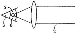
图2是示出使用图1的治疗装置在缺陷视觉矫正中向眼睛中引入脉冲激光辐射的原理的视图;2 is a view showing the principle of introducing pulsed laser radiation into the eye in defect vision correction using the treatment device of FIG. 1;
图3是图1的治疗装置的另一示意图;Fig. 3 is another schematic diagram of the treatment device of Fig. 1;
图4在子图(a)、(b)和(c)中示出在缺陷视觉的情况下说明人眼中矫正的需求的示意图;Figure 4 shows in subfigures (a), (b) and (c) a schematic diagram illustrating the need for correction in the human eye in the case of defective vision;
图5是通过眼睛角膜示出为了矫正缺陷视觉要去除的体的截面图;Figure 5 is a cross-sectional view through the cornea of an eye showing volume to be removed to correct defective vision;
图6是通过眼睛角膜的在图5的体去除之后的截面图;Figure 6 is a cross-sectional view through the cornea of the eye after the volume of Figure 5 has been removed;
图7是类似于图5的截面图;Figure 7 is a cross-sectional view similar to Figure 5;
图8是通过眼睛角膜的示出体去除的截面图;Figure 8 is a cross-sectional view through the cornea of the eye showing body removal;
图9a是在眼睛角膜上示出在缺陷视觉矫正期间生成的切割面的俯视图;Figure 9a is a top view on the cornea of the eye showing the cut planes generated during correction of defective vision;
图9b是相对于图9a的俯视图示出为了远视矫正去除体的概括的截面图;Figure 9b is a schematic cross-sectional view showing removal of the body for hyperopia correction relative to the top view of Figure 9a;
图10a是类似于图9a但是在矫正近视的情况下的视图;Figure 10a is a view similar to Figure 9a but with myopia corrected;
图10b是类似于图9a但是同样用于矫正近视的视图;Figure 10b is a view similar to Figure 9a but also for the correction of myopia;
图11a是类似于图9a但是相对于体的去除具有不同切割引导的视图;Figure 11a is a view similar to Figure 9a but with a different cutting guide relative to body removal;
图11b是类似于图9b但是用于图11a的俯视图的截面图;Figure 11b is a cross-sectional view similar to Figure 9b but for the top view of Figure 11a;
图12a是类似于图9a但是用于限制为了矫正缺陷视觉去除的体的不同类型边缘切割的截面图;Figure 12a is a cross-sectional view of a different type of edge cut similar to Figure 9a but used to limit the volume removed visually for correcting defects;
图12b是图9a的边缘切割的放大部分图;以及Figure 12b is an enlarged partial view of the edge cut of Figure 9a; and
图12c和12d是类似于图12b但是用于边缘面的不同几何的放大边缘切割视图。Figures 12c and 12d are enlarged edge cut views similar to Figure 12b but for a different geometry of the edge face.
具体实施方式 Detailed ways
图1示出与EP 1159986A1或US 5549632中所述类似的用于眼部外科方法的治疗装置1。治疗装置1通过治疗激光辐射2实现患者4的眼睛3中的缺陷视觉的矫正。缺陷视觉可包括远视、近视、老视、散光、混合性散光(散光包括在一个方向远视,在位于其直角的另一方向近视)、非球面缺陷和高阶像差。在上述实施例中施加治疗激光辐射2,作为聚焦在眼睛3中的脉冲激光束。在这种情况下,脉冲持续时间在例如飞秒范围内,并且激光辐射2通过在角膜中的非线性光效应起作用。激光束具有例如50至800fs短激光脉冲(优选地100-400fs),其具有10和500kHz之间的脉冲重复频率。在所述示例性实施例中,装置1的组件通过集成控制单元控制,但是这个单元当然还可以单独方式实现。Figure 1 shows a
在使用所述治疗装置之前,使用一个或多个测量装置来测量眼睛3的缺陷视觉。One or more measuring devices are used to measure the defective vision of the
图1a示意性示出治疗装置1。在这个变型中,治疗装置具有至少两个子装置或模块。激光装置L向眼睛3发出激光束2。在这种情况下,激光装置L完全自动运行,即,激光装置L在变换激光束2的相应开始信号时启动,并以这个方式生成切割面(其以随后所述的方式构成)并分离眼睛角膜中的体。激光装置L预先经由控制线(将不进行更详细地指定)从设计装置P接收运行所需的控制数据,作为控制数据组。传输发生在激光装置L的运行之前。当然,还可以无线地通信。作为直接通信的备选,还可设置空间上与激光单元L分离的设计单元P,并提供相应数据传输信道。FIG. 1 a schematically shows a
优选,将控制数据组发送至治疗装置1,并且还优选地,激光装置L的运行被阻止,直到在激光装置L上存在有效的控制数据组。有效的控制数据组可以是在原理上适用于治疗装置1的激光装置L的控制数据组。此外,有效性还可关联于通过的进一步测试,例如在控制数据组中额外提交的与治疗装置1相关的细节,如装置序列号,或与患者相关的细节,例如患者标识号,是否对应于例如从治疗装置读出的或只要患者处于操作激光装置L的正确位置就独立输入的其他细节。Preferably, the control data set is sent to the
设计单元P从治疗眼睛所需的治疗数据和缺陷视觉数据生成控制数据组,将其提供至激光单元L用于执行外科手术。经由接口S将他们供应至设计单元P,并且在示例性实施例中他们源自先前测量患者4的眼睛的测量装置M。当然,测量装置M可按任意期望方式向设计单元P发送相应测量和缺陷视觉数据。The design unit P generates a control data set from the treatment data and defect vision data required to treat the eye, which is supplied to the laser unit L for performing surgery. They are supplied to the design unit P via the interface S, and in the exemplary embodiment they originate from the measurement device M which previously measured the eye of the patient 4 . Of course, the measurement device M can send the corresponding measurement and defect vision data to the design unit P in any desired manner.
数据可通过存储器芯片(例如通过USB或存储器棒)、磁存储器(例如软盘)、通过无线电(例如WLAN、UMTS、蓝牙)或以硬线方式(例如USB、FireWire、RS232、CAN Bus、以太网等)发送。当然,在设计单元P和激光装置L之间的数据传输也可采用相同的方式。Data can be transmitted via memory chip (e.g. via USB or memory stick), magnetic storage (e.g. floppy disk), over radio (e.g. WLAN, UMTS, Bluetooth) or hardwired (e.g. USB, FireWire, RS232, CAN Bus, Ethernet, etc. )send. Of course, the same method can also be used for data transmission between the design unit P and the laser device L.
对于数据的传输在测量装置M到治疗装置1的直接无线电或有线连接(可以使用变型)具有如下优点:以最大可能的确定性排除错误的测量和缺陷视觉数据的使用。特别地,这特别应用于当患者通过床装置(图中未示出)从测量装置M或测量装置转移到激光装置L时,其中所述床装置通过如下方式与测量装置M或激光装置L交互:各个装置检测患者4是否在测量或引入激光辐射2的适当位置。这样,可在患者4从测量装置M转移至激光装置L的同时,将测量和缺陷视觉数据发送至治疗设备1。A direct radio or wired connection (variants are possible) from the measuring device M to the
优选地,适当的装置确保设计单元P始终生成与患者4相关的控制数据组,并且不正确的控制数据组的错误使用的风险几乎被排除。Preferably, suitable means ensure that the design unit P always generates control data sets relevant to the patient 4 and that the risk of misuse of incorrect control data sets is practically ruled out.
图2中示意性示出激光束2的效应。治疗激光束2通过未指定的光学元件聚焦于眼睛6的角膜5。在角膜5中生成焦点,其覆盖点6,并且其中激光辐射能量密度很高,以致于在眼睛中出现与脉冲长度相结合的非线性效应。例如,脉冲激光辐射2的每个脉冲可在眼睛5的角膜中的各个点6处生成光击穿,这个击穿随后启动在图2中示意性指出的等离子体泡。结果,在角膜5中,通过这个激光脉冲分离组织。尽管仅在焦点中实现生成击穿的状态,当生成等离子体泡时,组织层分离包括激光辐射2的焦点覆盖的比点6更大的区域。为了通过每个激光脉冲生成光击穿,能量密度(即激光辐射的流量)必须大于一定的、依赖于脉冲长度的阈值。这个关系根据例如DE 69500997T2是本领域普通技术人员已知的。The effect of the
备选地,还可这样生成脉冲激光辐射的组织分离效应,在一个区域(重叠于多个激光辐射脉冲的点6)中发出多个激光辐射脉冲。然后,多个激光辐射脉冲协作以实现组织分离效应。Alternatively, the tissue-splitting effect of the pulsed laser radiation can also be generated in such a way that a plurality of laser radiation pulses are emitted in one region (
然而,治疗装置1使用的组织分离的类型与下文的描述无关;重要的是使用脉冲的治疗激光辐射2。例如,可通过如WO 2004/032810A2所述的治疗装置1。还重要地,大量激光脉冲聚焦形成组织中切割面,其形状取决于激光脉冲焦距在/设置在组织中的图形。图形预定了焦点位置的目标点,其中在所述点处发出一个或多个激光脉冲(多个),并且预定了切割面的形状和位置。目标点的图形对于以下所述的方法和设备很重要,并且以下将更详细描述图形。However, the type of tissue separation used by the
现在,为了执行缺陷视觉的矫正,通过分离组织的那些层利用脉冲激光辐射从角膜5中的区域去除物质,由此隔离物质,并随后使得物质去除。物质的去除影响了角膜中的体的改变,导致角膜5的光学成像效应的改变,其尺度是精确的,因此以致于先前确定的缺陷视觉尽可能地被矫正。为了隔离要去除的体,将激光辐射2的焦点引导至角膜5中的目标点,通常在定位于上皮和Bowman薄膜以下并且Descemet薄膜和内皮以上的区域中。为此,治疗装置具有在角膜5中移动激光辐射2的焦点位置的机构。这在图3中示意性示出。Now, to perform the correction of defective vision, the material is removed from the area in the
在图3中包括治疗装置1的元件,仅限于理解焦点的转移所需。如上所述,激光辐射2聚焦于角膜5中的焦点7,并且在角膜中的焦点7的位置转移,从而为了在各个点处生成切割面,向角膜5的组织中引入从激光辐射脉冲聚焦的能量。通过激光8提供激光辐射2作为脉冲辐射。xy扫描仪9(其通过围绕基本正交的轴偏斜的两个电流计镜在变型中实施)二维地偏斜来自激光8的激光束,从而在xy扫描仪9之后,出现偏斜的激光束10。因此,xy扫描仪9使得基本垂直于激光辐射2的入射主方向的焦点7的位置移动至角膜5中。除了xy扫描仪9,提供z扫描仪11(其作为例如可调节望远镜实施)用于调节深度位置。z扫描仪11提供焦点7的z位置(即其在入射光轴上的位置)用于移动。z扫描仪11可设置在xy扫描仪9的下游或上游。因此,以下通过x、y、z指示的坐标涉及焦点7的位置的移动。The inclusion of elements of the
对于治疗装置1的作用原理,对于空间方向的各个坐标的分配并非必不可少;然而,为了说明简单的目的,以下z指示沿着激光辐射2的入射光轴的坐标的所有情况,x和y指示在垂直于激光束入射方向的屏幕中相互正交的坐标。当然,本领域普通技术人员知道,在角膜5中的焦点7的位置还可以是其他坐标系统中所述的三维;具体地,坐标系统不必是矩形坐标系统。因此,xy扫描仪9围绕轴彼此偏斜直角并非强制性的;相反,可使用能够在不含光辐射的入射轴的平面内调节焦点7的任何扫描仪。因此,斜角坐标系统也是可能的。For the principle of action of the
此外,非直线坐标系统也可用于描述或控制焦点7的位置,将在以下更详细论述。这种类型的坐标系统的实例有球形坐标以及柱形坐标。Furthermore, non-rectilinear coordinate systems can also be used to describe or control the position of the focal point 7, as will be discussed in more detail below. Examples of this type of coordinate system are spherical coordinates as well as cylindrical coordinates.
为了控制焦点7的位置,xy扫描仪9以及z扫描仪11(共同形成三维焦点移动装置的特定实例)经由未指定的线路通过控制器12致动。激光器8也是如此。控制器3确保激光器8以及三维焦点移动装置的适当同步操作(通过xy扫描仪9以及z扫描仪11以示例性方式实现),从而角膜5中的焦点7的位置以最终分离特定体的材料的方式移动,随后去除影响缺陷视觉的期望矫正的体。To control the position of the focal point 7, the xy scanner 9 and the z scanner 11 (together forming a specific example of a three-dimensional focus moving device) are actuated by a controller 12 via unspecified lines. The same is true for laser 8 . The
控制器12根据限定焦点移动的目标点的预定控制数据运行。通常,将控制数据概括在控制数据组中。在一个实施例中,控制数据组将目标点的坐标定义为图形,其中在控制数据组中的目标点的序列定义焦点位置的连续设置,并因此最终定义路径曲线(在本文中还简称为路径)。在一个实施例中,控制数据组包含目标点作为用于焦点位置移动机构的特定设置值,例如用于xy扫描仪9和z扫描仪11。为了准备眼科外科方法,即,在执行实际外科方法之前,在图形中确定目标点以及优选地其顺序。外科治疗必须被预先设计,其方式为定义治疗装置1的控制数据,其数据的应用随后实现对于患者4最佳的缺陷视觉的矫正。The controller 12 operates according to predetermined control data defining a target point for focus movement. Typically, the control data are summarized in a control data set. In one embodiment, the control data set defines the coordinates of the target points as a graph, wherein the sequence of target points in the control data set defines a continuous set of focus positions and thus ultimately defines a path curve (also referred to herein simply as path ). In one embodiment, the control data set contains the target point as a specific setting for the focus position shifting mechanism, for example for the xy scanner 9 and the z scanner 11 . In order to prepare the ophthalmic surgical procedure, ie before carrying out the actual surgical procedure, the target points and preferably their sequence are determined in the graph. The surgical treatment has to be planned in advance by defining the control data of the
第一步是定义要从角膜5分离并随后去除的体。如参照图1a先前所述,这需要确定矫正的需求。图4示出子图a)、b)和c),患者4的眼睛中的光学状态。在未缺陷视觉矫正时,情况如子图a)所示。角膜5与眼睛的晶状体13一起影响位于无限远的物体聚焦在位于视网膜14之后的轴z上的焦点F。在这种情况下,成像效应一方面来源于眼睛的晶状体13(当眼睛不适时,晶状体放松),以及另一方面来源于眼睛的角膜5,其基本上通过角膜的前面15和角膜的背面16定义,并且同样由于其曲率也具有成像效应。角膜5的光效应通过角膜的前表面的曲率半径RCV引起。子图a)仅以示例性方式表示缺陷视觉;实际上,可存在上述更复杂的缺陷视觉。然而,以下描述也同样适用,尽管某些具体等式可随后包含额外角度依赖性,尽管没有明确引用。The first step is to define the volume to be separated and subsequently removed from the
为了矫正缺陷视觉,以一副眼镜形式的前透镜17通过已知方式位于在眼睛3之前距离角膜5的顶点dHS处,如图4的子图b)所示。透镜17的折射光焦度BBR被修改,从而透镜作为整体移动系统的远点,即,由一副眼镜和眼睛构成的系统从焦点F移动至矫正的焦点F*(位于视网膜14上)。In order to correct defective vision, the
对于本说明书中使用的命名,应注意,对于变量增加星号表示他们是在矫正之后获得的变量。因此,焦点F*是在光矫正之后出现的焦点,这是通过一副眼镜的透镜17实现的,如图4的子图b)。For the nomenclature used in this specification, it should be noted that adding an asterisk to variables indicates that they are variables obtained after rectification. Thus, the focal point F * is the focal point that occurs after light correction, which is achieved by the
在合理的假设:角膜5的厚度的改变主要改变了角膜的面向空气的前表面15的曲率半径,但是未改变面向眼镜内部的角膜的后表面16的曲率半径,因此通过去除体来修改角膜的前表面15的曲率半径RCV。It is reasonable to assume that a change in the thickness of the
由体减少的角膜5具有通过随后矫正的焦点F*位于视网膜14上的方式改变的成像效应。在矫正之后,存在角膜的改变的前表面15*,并且即使没有一副眼镜也实现缺陷视觉的矫正。The volume-reduced
因此,确定角膜的修改前表面15*要实现的曲率,以定义目标点的图形。在这种情况下,在确定相应参数是眼用光学元件中标准方法时,开始点是一副眼镜的透镜17的折射光焦度。以下公式适于一副眼镜的透镜17的折射光焦度BBR(φ):Thus, the curvature to be achieved of the modified
(1)BBR(φ)=Sph+Cyl·sin2(φ-θ)(1)B BR (φ)=Sph+Cyl·sin 2 (φ-θ)
在该等式中,Sph和Cyl指球形和散光折射缺陷分别实现的矫正值,θ指柱形(散射)缺陷视觉的柱轴的位置,例如,在验光时是本领域普通技术人员已知的。最后,参数φ指的是眼睛的柱坐标的系统,并且在看向眼睛时逆时针计数,例如在眼用光学元件中常规的。现在,通过值BBR,如下设置角膜的修改的前表面15*的曲率:In this equation, Sph and Cyl refer to the correction values achieved for spherical and astigmatic refractive defects, respectively, and θ refers to the position of the cylindrical axis of cylindrical (scattering) defect vision, for example, as is known to those of ordinary skill in the art in optometry . Finally, the parameter φ refers to the system of cylindrical coordinates of the eye and counts counterclockwise when looking towards the eye, such as is conventional in ophthalmic optics. Now, via the value B BR , the curvature of the modified
(2)RCV *=1/((1/RCV)+BBR/((nc-1)·(1-dHS·BBR)))+F(2) R CV * =1/((1/R CV )+B BR /((n c -1)·(1-d HS ·B BR )))+F
在等式(2)中,nc指角膜材料的折射光焦度。各个值通常为1.376;dHS指具有折射光焦度BBR的一副眼镜必须位于远离角膜顶点的距离,以通过一副眼镜生成缺陷视觉的期望矫正;BBR指根据等式(1)的一副眼镜的上述折射光焦度。对于折射光焦度BBR的指示还可包括除正常球形或柱形矫正之外的缺陷。然后,BBR(因此,自动地RCV *)具有额外坐标相关性。In equation (2), nc refers to the refractive power of the corneal material. The respective values are typically 1.376; d HS refers to the distance that a pair of spectacles with refractive power B BR must be located away from the apex of the cornea to produce the desired correction of defective vision by a pair of spectacles; B BR refers to the distance according to equation (1) The above refractive power of a pair of eyeglasses. Indications for the refractive power B BR may also include defects other than normal spherical or cylindrical correction. Then, B BR (and thus automatically RCV * ) has an additional coordinate dependency.
矫正因子F考虑角膜厚度的改变的光效应,并且可看作第一近似中的恒定因子。为了高精度矫正,可根据以下等式计算因子:The correction factor F takes into account the light effect of changes in corneal thickness and can be seen as a constant factor in a first approximation. For high-precision corrections, the factor can be calculated according to the following equation:
(3)F=(1-1/nc)·(dC *-dC)(3) F=(1-1/n c )·(d C * -d C )
在这种情况下,dC和dC *分别是光矫正之前和之后的角膜厚度。为了精确确定,RCV *被迭代计算,从而在第i计算中,从差(RCV *-RCV)推导变量(dC *-dC),并且将从其获得的用于厚度改变的结果应用于第(i+1)计算。这可执行,直到满足最终标准,例如,如果厚度改变的结果的差在两个连续迭代步骤中小于相应定义限度。这个限定可经由恒定差来定义,例如相应于适于治疗的折射矫正的精度。In this case, dC and dC * are the corneal thickness before and after photocorrection, respectively. For accurate determination, R CV * is calculated iteratively, so that in the i-th calculation, the variable (d C * -d C ) is derived from the difference (R CV * - R CV ), and the obtained value for the thickness change is used The result is applied to the (i+1)th calculation. This may be performed until a final criterion is met, for example if the difference in the results of the thickness change is less than a corresponding defined limit in two successive iteration steps. This limit can be defined via a constant difference, for example corresponding to the precision of the therapeutically appropriate refractive correction.
如果不管眼睛角膜厚度的改变(对于简化方法完全可允许),则可将等式(2)中的矫正值F设置为0用于简化计算,即,不管和忽略。意外地,获得以下简单等式用于修改的角膜5*的折射光焦度:If the change in corneal thickness of the eye is ignored (perfectly permissible for the simplified method), the correction value F in equation (2) can be set to 0 for simplified calculations, ie ignored and ignored. Surprisingly, the following simple equation was obtained for the modified
BCV *=BCV+BBR/(1-BBR·dHS)B CV * =B CV +B BR /(1-B BR ·d HS )
这个等式通过等式BCV *=(n-1)/RCV *以简单方式向本领域普通技术人员提供了角膜的前表面15*的半径RCV *,其必须在修改之后如下出现以获得缺陷视觉的期望矫正:RCV *=1/((1/RCV)+BBR/((nc-1)·(1-dHS·BBR)))。This equation provides the person of ordinary skill in the art in a simple manner the radius R CV * of the
对于体,其的去除影响了角膜的前表面15的曲率的上述改变,现在定义分离体的边界面。由此,优选地必须考虑如下事实:如果可能在适应黑暗的眼睛的瞳孔的尺寸上扩展,则矫正区域的直径,并因此去除体的直径。For the volume, the removal of which affects the aforementioned change in curvature of the
在第一变型中,使用本领域普通技术人员已知的多种方法来定义限定体的自由面,所述体的去除影响曲率的改变。为此,沿着z轴确定曲率的预期修改所需的厚度改变。这根据r、φ(柱坐标)提供体,并且这随后提供其边界面。In a first variant, various methods known to the person skilled in the art are used to define free surfaces defining volumes, the removal of which affects the change in curvature. To this end, the thickness change required for the desired modification of the curvature is determined along the z-axis. This provides the volume in terms of r, φ (cylindrical coordinates), and this in turn provides its boundary surfaces.
简单的分析计算导致以下第二变型,其中通过两个面部分构成体的边界面:面向角膜的表面15的前面部分和相对的后面部分。图5示出相应状态。体18通过位于角膜的前表面15下方恒定距离dF处的前切割面19限定为朝向角膜的前表面15。该前切割面19还称为(通过激光角膜刀模拟)瓣面19,因为其允许,在眼睛的角膜5中,与朝向边缘的开口切割结合,薄层以瓣的形式从下面的角膜5升起。当然,这种除去预先隔离的体18在这里也是可以的。Simple analytical calculations lead to the following second variant, in which the boundary surface of the volume is constituted by two facets: the anterior portion of the cornea-facing
前切割面19具有通过角膜的前表面15下方的dF所定位的曲率段。如果在外科治疗期间前表面是球形,则可对于瓣面19指定比曲率半径RCV小dF的曲率半径。如对于优选变型的下文所述,接触镜可确保在生成切割面19时角膜的前表面15是球形(在生成切割面的时刻),从而目标点的图形生成球形切割面。尽管在接触镜的拆除之后眼睛3的放松可随后导致非球形切割面19,但是其仍旧在与角膜的前表面15或15*的恒定距离处。The
其次,要从角膜5去除的体18由后切割面20(其通常不在与角膜的前表面15的恒定距离处)限定。因此,后切割面20将实施为使得体18具有透镜体的形式,由此后切割面20还称为透镜体面20。在图5中通过实例示出用于近视矫正的后切割面,同样地如具有曲率半径RL的球形面,其中这个曲率的中心与角膜的前表面15的曲率(同样是图5中的球形)的中心不一致。在远视矫正中,RL大于RCV-dF。Secondly, the
图6示出在去除体18之后的状态。角膜的修改的前表面15*的半径现在是RCV *,并且可根据例如之前所述的等式计算。在这种情况下,去除的体18的中心厚度dL决定了半径改变,如图7所示。在该图中,球形帽的高度hF可通过前切割面19来定义,球形帽的高度hL可通过后切割面20来定义,并且要去除的体18的厚度dL也可指示为其他变量。FIG. 6 shows the state after removal of the
由于在角膜的前表面15和前切割面19之间的恒定距离,后切割面20定义了在去除体18之后的角膜的前表面15*的曲率段。因此,例如,在考虑柱形参数进行缺陷视觉矫正时,后切割面20将具有依赖于角度的曲率半径。对于图7中所示的透镜体面20,通常应用以下等式:Due to the constant distance between the
RL(φ)=RCV *(φ)-dF R L (φ)=R CV * (φ)-d F
或,在柱坐标(z,r,φ)中:Or, in cylindrical coordinates (z, r, φ):
zL(r,φ)=RL(φ)-(RL 2(φ)-r2)1/2+dL+dF z L (r, φ)=R L (φ)-(R L 2 (φ)-r 2 ) 1/2 +d L +d F
当未考虑散光时,排除对于φ的依赖性,并且透镜体面20是球面。然而,考虑缺陷视觉的柱矫正的需求,透镜体面20通常具有在各个轴上不同的曲率半径,并且曲率半径当然大部分具有相同顶点。When astigmatism is not considered, the dependence on φ is excluded and the
此外,这自然清楚地,在近视柱矫正的情况下,在瓣面19和透镜体面20之间的交点的理论线不位于一个平面,即,在恒定z坐标处。透镜体面20的曲率的最小曲率半径是φ=θ+π/2;当然,最大半径在柱面缺陷视觉的轴θ上,即φ=θ。与图7所示不同,在缺陷视觉的矫正时,瓣面19和透镜体面20的顶点理论上一致,并且透镜体面20比瓣面19弯曲地更强烈。获得透镜体的厚度dL,作为近视的中心透镜体厚度。Furthermore, it is naturally clear that in the case of myopic cylinder correction the theoretical line of the intersection between the
在近视矫正的情况下,作为透镜体的体18理论上在边缘处具有透镜体面20和瓣面19的交线。在远视矫正时,始终提供有限的边缘厚度,因为透镜体面20没有瓣面19弯曲地大。然而,在这种情况下,中心透镜体密度理论上等于0。In the case of myopia correction, the
除了瓣面20和透镜体面19,提供额外边缘面,其在边缘处限定由瓣面20和透镜体面19限定的体18。还使用脉冲激光束执行该边缘面的切割。以下参照图12a-c描述边缘面的结构。In addition to the
在远视矫正时,通常提供有限的边缘厚度,因为透镜体面20没有瓣面19弯曲地大。然而,在这种情况下,中心透镜体密度理论上等于0。除了瓣面20和透镜体面19,提供额外边缘面,其在边缘处隔离由瓣面20和透镜体面19限定的体18。还使用脉冲激光束执行该边缘面的切割。In the case of hyperopic correction, a limited edge thickness is usually provided, since the
由在角膜的前面15的恒定距离处的前切割面19以及后切割面20限定的体18的图中所示实施例仅是限定体18的一个选择。然而,其具有以下优点:基本通过仅一个面(透镜体面20)限定光矫正,从而边界面的其他面部分的分析描述更简单。The embodiment shown in the figures of the
此外,从角膜的前表面15和角膜的后表面16相对于体的距离提供最佳安全余量。在角膜的前切割面19和前表面15之间的剩余厚度dF可设置为例如从50到200微米的恒定值。具体地,可这样的选择:疼痛敏感的上皮保持在角膜的前表面15下方的瓣面19所形成的薄片中。球形瓣面19的形成还取决于先前角膜曲率计切割;这对于接受该方法是有利的。Furthermore, the distance relative to the body from the
在生成切割面19和20之后,随后从角膜5去除由此隔离的体18。这在图8中示意性表示,图8还示出例如通过等离子体泡的连续设置在焦点锥体21中入射的治疗激光束的作用下生成切割面19和20,从而在优选实施例中,通过适当三维地移动脉冲激光辐射2的焦点位置生成瓣切割面19和透镜体切割面20。After the cutting planes 19 and 20 have been produced, the
然而,备选地,在简化实施例中,可利用脉冲激光辐射通过在距离角膜的前表面15恒定距离处限定弯曲切割面19的目标点来形成瓣面19,以及可通过例如使用激基激光束通过激光烧蚀来去除体18。为此,可将透镜体面20定义为去除的边界面,尽管这不是必须的。然后,治疗装置1如已知的激光角膜刀一样工作;但是,在弯曲的角膜上生成切割面19。以上和以下分别所述的特征在这种变型中都是可能的,特别地只要涉及到边界面、其几何定义的确定以及控制参数的确定。Alternatively, however, in a simplified embodiment, the
如果通过脉冲激光辐射生成透镜体面20和瓣面19,则在瓣面19之前形成透镜体面20是有利的,因为如果在透镜体面20上没有发生角膜5的改变,在透镜体面20中的光结果更好(或设置仅可实现)。If the
如图8所示,可通过允许体18在图8中所示的箭头23的方向中提取的边缘切割22来实现由脉冲激光辐射分离的体18的去除。然而,备选地,可通过如下方式实现边缘切割22:其以到角膜的前表面15的环的形式连接前切割面19(即瓣面19),但是边缘切割没有围绕360°角延伸。这样分离的薄片保持在窄区域内连接至角膜5的剩余组织。然后,这个连接桥用作铰链,以能够将其他分离的薄片远离角膜5折叠,以及从眼睛的角膜5的剩余部分分离通过该方式可触的已经隔离的体18。当分别生成控制数据或目标点时,可预定义连接桥的位置。从而,由此所述的过程或装置分离角膜5中的体19,并生成薄片,其经由组织桥连接至眼睛的角膜的剩余部分,作为体上的盖。所述盖可被折叠,并且可去除体18。As shown in FIG. 8 , removal of the
为了生成切割面19和20,可以多种方法设置目标点。现有技术(例如WO 2005/011546)描述了可使用什么样的特定螺旋线(其例如以围绕基本垂直于光轴(z轴)的主轴的螺旋状线的方式延伸)在眼睛的角膜中生成切割面。扫描图形的使用(在线中设置目标点)也是已知的(见WO2005/011545)。显然地,可使用这些选择生成上述切割面。In order to generate the cutting planes 19 and 20, the target points can be set in various ways. The prior art (e.g. WO 2005/011546) describes what specific helixes (which e.g. extend in the manner of a helical line around a major axis substantially perpendicular to the optical axis (z-axis)) can be used to generate in the cornea of the eye cut surface. The use of scan patterns (setting target points in a line) is also known (see WO2005/011545). Clearly, these selections can be used to generate the cut surfaces described above.
在图9a和9b中可更详细地看见上述边缘面。在这些图中通过相同标号提供参照其他图已经描述的元素,从而不必再次描述他们。The aforementioned edge faces can be seen in more detail in Figures 9a and 9b. Elements already described with reference to other figures are provided in these figures by the same reference numerals so that they do not have to be described again.
图9a是在远视矫正情况下的角膜的前表面15上的俯视图,其中包括瓣面19以及透镜体面20(其边缘通过虚线指示)以及边缘切割22。图9a中还可看见由边缘面24实现的在透镜体面20的边缘和瓣面19之间的转换的区域。图9b中清楚可见这个边缘面24,图9b是图9a的视图沿线A-A的截面图。Fig. 9a is a top view on the
现在,图9b(以及类似地以下图10b、11b和12a)所示的透镜体具有最小厚度,在远视矫正透镜体的情况下其位于视觉轴OA的区域中,但是在近视矫正时位于透镜体的边缘。最小厚度dM或dL确保以透镜体18形式要去除的组织部分足够稳定,从而在去除期间没有颗粒脱落或组织部分没有裂开。优选地,最小厚度在从5至50微米的范围内。在这种情况下,通过构成眼睛的角膜的薄片层的层厚度提供更低的限值。基本不小于5微米确保了透镜体仍旧在其最薄点处具有至少一个薄片层,由此提供足够的稳定性。Now, the lens body shown in Figure 9b (and similarly in Figures 10b, 11b and 12a below) has a minimum thickness which lies in the region of the optical axis OA in the case of a hyperopic correction lens body, but in the case of a myopia correction lens body the edge of. The minimum thickness dM or dL ensures that the tissue part to be removed in the form of the
边缘面24影响了从透镜体面20到瓣面19的转换。在这种情况下,在图9b的实施例中其被设计为锥面,其相比于(在图9a的俯视图上的)可能定位的圆锥面位置更加倾斜,后者垂直于角膜的前面15或垂直于平行延伸的瓣面19定位。边缘切割22位于与视觉轴OA成角度α处,这个角度导致相对于角膜的前面的垂直段。The edge face 24 affects the transition from the lens body face 20 to the
另一方面,边缘面24以更加倾斜方式延伸,从而当从光轴OA的方向上方或沿着该方向观察时边缘面24具有的宽度B大于例如边缘切割22。由此,相应角度β也大于角度α。On the other hand, the
图10a和10b示出在近视透镜体的情况下(即在近视矫正时)的相应状态。在这种情况下,同样,提供边缘面24,并且其导致透镜体18的有限边缘厚度,这本身在考虑相比于瓣面10的更大曲率的透镜体面20时不提供,因为两个面至少在他们的延长部分具有交线,即,边缘将在交线中结束。10a and 10b show the corresponding states in the case of a myopic lens body, ie during myopia correction. In this case, too, an
因此,根据图9b以远视形式存在的透镜体18的最小厚度出现在光轴OA上或接近于此,在根据图10b的近视透镜体中出现在边缘。由此,在图10b中的边缘处还示出最小厚度dM。在这种情况下,同样,最小厚度具有以下效应:透镜体在去除期间足够稳定。Thus, the minimum thickness of the
显然,图9b和10b的截面视图仅在不存在更高阶矫正(特别地,没有散光)时针对透镜体作为整体进行描述。如果存在散光,则相应地矫正透镜体面20以区别于球面;这还通过本领域普通技术人员已知方式影响了边缘面24。Obviously, the cross-sectional views of Figures 9b and 10b are only described for the lens body as a whole when no higher order corrections are present (in particular, no astigmatism). If astigmatism is present, the lens body face 20 is corrected accordingly to differ from the spherical face; this also affects the edge faces 24 in a manner known to those of ordinary skill in the art.
最后,图11a和11b示出于图9a和9b相应的状态;然而,在这种情况下,被生成以暴露透镜体18的边缘切割22在相比于图9和10更大角度范围上延伸。Finally, FIGS. 11a and 11b show the corresponding state in FIGS. 9a and 9b; however, in this case the edge cut 22 created to expose the
图9至11示出被设计为斜切的边缘面24。然而,边缘面24还具有与在截面中观察的线性段不同的结构。这通过图12a至d的实例示出。在这些图中,图12a代表与图9b、10b或11b类似的截面图。图12b至12d是由图12中的虚线指示的细节的放大图,并且代表对于边缘面24的结构的不同方案。9 to 11 show edge faces 24 which are designed as chamfers. However, the
根据图12b,边缘面24包含2个部分25和26,他们在截面中基本是线性。第一部分25垂直于瓣面19。第一部分25的高度影响边缘的厚度dR。优选地,选择该厚度,以在从5至10微米的范围内,并确保当去除透镜体18时在边缘面24的范围内碎片不脱落。该碎片将具有对于内向生长很不利的影响,并将导致不希望的衰退。为了当去除透镜体时实现由瓣切割19分离的角膜薄片27的平滑定位(尽管第一部分25垂直位于瓣面19),在图12b的实施例中,边缘面24的第二部分26具有朝向视觉轴的倾斜段。该倾斜段随后提供宽度B,其显著大于在垂直于瓣面19延伸的边缘24中提供的宽度。According to Fig. 12b, the
图12c示出图12b的边缘面24的结构的修改,其中在垂直于瓣面19的第一部分25上形成连续弯曲的第二部分26,其在远离眼睛角膜的前表面15的区域中在透镜体面20和瓣面19之间成圆形。第一部分25的垂直磨合再次确保最小边缘厚度dR,其防止在去除透镜体组织时组织部分从透镜体边缘脱落。优选地,最小边缘厚度是与中心厚度dM相同的量级。Fig. 12c shows a modification of the structure of the
在根据图12d的边缘结构(以S形方式实现)中,这也可同样实现垂直于瓣面19的第一部分25。在考虑S形结构时,边缘面24的截面视图在这个配置中具有转折点,并且优选地第二部分26同样在透镜体面20中以直角结束。In the edge structure according to FIG. 12d (implemented in an S-shaped manner), this can likewise be achieved perpendicular to the
接触镜具有其他优点:由于压在接触镜的球形下面26的结果,角膜的前表面15也自动地是球形。因此,当按压在接触镜上时,位于角膜的前表面15下方恒定距离处的前切割面19也是球形,导致大大简化控制。因此,优选地,独立于其他特征,使用在下面具有球形接触镜的接触镜,并通过前切割面19以及后切割面限制体,在角膜的前表面15以下的恒定距离dF处作为球形面生成前切割面。后切割面的弯曲段不是从角膜的前表面分离距离dF,而是对应于在眼睛放松时即在卸下接触镜之后用于校正缺陷视觉所期望的部分。同样情况分别适用于目标点的限定和操作方法。Contact lenses have an additional advantage: the
Claims (11)


Applications Claiming Priority (3)
| Application Number | Priority Date | Filing Date | Title |
|---|---|---|---|
| DE102007053281A DE102007053281A1 (en) | 2007-11-08 | 2007-11-08 | A treatment device for operative vision correction of an eye, a method for generating control data therefor and methods for surgical correction of defective vision of an eye |
| DE102007053281.6 | 2007-11-08 | ||
| PCT/EP2008/009247 WO2009059730A1 (en) | 2007-11-08 | 2008-11-03 | Treatment device for operatively correcting defective vision of an eye, method for producing control data therefor and method for operatively correcting defective vision of an eye |
Publications (2)
| Publication Number | Publication Date |
|---|---|
| CN101896144A CN101896144A (en) | 2010-11-24 |
| CN101896144B true CN101896144B (en) | 2013-12-11 |
Family
ID=40416929
Family Applications (1)
| Application Number | Title | Priority Date | Filing Date |
|---|---|---|---|
| CN2008801152451A Active CN101896144B (en) | 2007-11-08 | 2008-11-03 | Treatment device for operatively correcting defective vision of an eye, method for producing control data therefor and method for operatively correcting defective vision of an eye |
Country Status (6)
| Country | Link |
|---|---|
| US (3) | US9084667B2 (en) |
| EP (1) | EP2211804B1 (en) |
| KR (2) | KR101752482B1 (en) |
| CN (1) | CN101896144B (en) |
| DE (1) | DE102007053281A1 (en) |
| WO (1) | WO2009059730A1 (en) |
Families Citing this family (61)
| Publication number | Priority date | Publication date | Assignee | Title |
|---|---|---|---|---|
| US8668735B2 (en) | 2000-09-12 | 2014-03-11 | Revision Optics, Inc. | Corneal implant storage and delivery devices |
| US10835371B2 (en) | 2004-04-30 | 2020-11-17 | Rvo 2.0, Inc. | Small diameter corneal inlay methods |
| US10555805B2 (en) | 2006-02-24 | 2020-02-11 | Rvo 2.0, Inc. | Anterior corneal shapes and methods of providing the shapes |
| US9271828B2 (en) | 2007-03-28 | 2016-03-01 | Revision Optics, Inc. | Corneal implant retaining devices and methods of use |
| US9549848B2 (en) | 2007-03-28 | 2017-01-24 | Revision Optics, Inc. | Corneal implant inserters and methods of use |
| DE102007053281A1 (en) * | 2007-11-08 | 2009-05-14 | Carl Zeiss Meditec Ag | A treatment device for operative vision correction of an eye, a method for generating control data therefor and methods for surgical correction of defective vision of an eye |
| US9539143B2 (en) | 2008-04-04 | 2017-01-10 | Revision Optics, Inc. | Methods of correcting vision |
| US8377048B2 (en) * | 2009-01-06 | 2013-02-19 | Technolas Perfect Vision Gmbh | Minimizing the side-effects of refractive corrections using statistically determined irregularities in intrastromal incisions |
| DE102009005482A1 (en) | 2009-01-21 | 2010-07-22 | Carl Zeiss Meditec Ag | Device and method for generating control data for the surgical ametropia correction of an eye |
| US9974690B2 (en) * | 2009-03-23 | 2018-05-22 | Wavelight Gmbh | Apparatus and method for LASIK |
| US9095414B2 (en) * | 2011-06-24 | 2015-08-04 | The Regents Of The University Of California | Nonlinear optical photodynamic therapy (NLO-PDT) of the cornea |
| DE102011108645A1 (en) * | 2011-07-22 | 2013-01-24 | Carl Zeiss Meditec Ag | "Aftercare for ophthalmic refractive correction" |
| DE102011083928A1 (en) | 2011-09-30 | 2013-04-04 | Carl Zeiss Meditec Ag | A treatment device for operative vision correction of an eye, a method for generating control data therefor and methods for surgical correction of defective vision of an eye |
| CA2849371C (en) * | 2011-10-10 | 2017-03-07 | Alcon Inc. | System, interface devices, use of the interface devices for eye surgery |
| DE102011085046A1 (en) | 2011-10-21 | 2013-04-25 | Carl Zeiss Meditec Ag | Generation of cut surfaces in a transparent material by means of optical radiation |
| AU2012325705B2 (en) | 2011-10-21 | 2017-07-20 | Revision Optics, Inc. | Corneal implant storage and delivery devices |
| PL2804571T3 (en) * | 2012-01-18 | 2019-09-30 | Wavelight Gmbh | Adjusting laser energy in accordace with optical density |
| TWI588560B (en) | 2012-04-05 | 2017-06-21 | 布萊恩荷登視覺協會 | Lens, device, method and system for refractive error |
| US10058453B2 (en) | 2012-04-24 | 2018-08-28 | Wavelight Gmbh | Extracting lenticules for refractive correction |
| DE102012018421A1 (en) * | 2012-09-14 | 2014-03-20 | Carl Zeiss Meditec Ag | Planning device for producing control data for treating device for myopia correction with and without astigmatism of visually impaired patient, has calculating unit determining cornea-cut surface so that surface is formed from partial areas |
| DE102013218415A1 (en) | 2012-09-14 | 2014-04-10 | Carl Zeiss Meditec Ag | Eye surgery procedure |
| US9201250B2 (en) | 2012-10-17 | 2015-12-01 | Brien Holden Vision Institute | Lenses, devices, methods and systems for refractive error |
| HK1212194A1 (en) | 2012-10-17 | 2016-06-10 | Brien Holden Vision Institute | Lenses, devices, methods and systems for refractive error |
| DE102012022080A1 (en) * | 2012-11-08 | 2014-05-08 | Carl Zeiss Meditec Ag | Eye surgery procedure |
| DE102012022079A1 (en) * | 2012-11-08 | 2014-05-08 | Carl Zeiss Meditec Ag | Eye surgery procedure |
| DE102013004688A1 (en) * | 2013-03-13 | 2014-09-18 | Carl Zeiss Meditec Ag | Eye surgery procedure |
| DE102013204496A1 (en) | 2013-03-14 | 2014-09-18 | Carl Zeiss Meditec Ag | Creation of curved cuts in the interior of the cornea |
| CN107072821B (en) | 2014-09-09 | 2022-07-01 | 卢米希拉公司 | Multi-wavelength phototherapy devices, systems, and methods for non-invasive treatment of damaged or diseased tissue |
| CA2962430C (en) | 2014-09-25 | 2023-03-28 | Amo Development, Llc | Systems for lenticular laser incision |
| US10709611B2 (en) * | 2014-09-25 | 2020-07-14 | Amo Development, Llc | Systems and methods for lenticular laser incision |
| DE102015002729A1 (en) * | 2015-02-27 | 2016-09-01 | Carl Zeiss Meditec Ag | Ophthalmic laser therapy device and method for generating corneal access incisions |
| WO2016144404A1 (en) | 2015-03-12 | 2016-09-15 | Revision Optics, Inc. | Methods of correcting vision |
| KR101581834B1 (en) * | 2015-03-24 | 2015-12-31 | 박기성 | Integrated corneal photoablation system for correction of both shape error and curvature error |
| EP3135261B1 (en) | 2015-08-31 | 2021-01-27 | Cesar C. Carriazo | Treatment apparatus for correcting a refractive error of an eye |
| US10772763B2 (en) | 2015-08-31 | 2020-09-15 | Cesar C. Carriazo | Treatment apparatus for correcting a refractive error of an eye |
| DE102015218909A1 (en) | 2015-09-30 | 2017-03-30 | Carl Zeiss Meditec Ag | Eye surgery procedure |
| KR101654539B1 (en) * | 2016-02-03 | 2016-09-07 | 정영택 | Adapter of laser for eye surgery having a laser beam non-irradiated areas |
| US11065156B2 (en) * | 2016-06-29 | 2021-07-20 | Amo Development, Llc | Lenticular laser incision for low myopia and/or hyperopia patients |
| DE102017107915A1 (en) | 2016-07-18 | 2018-01-18 | Carl Zeiss Meditec Ag | System for eye therapy by tissue treatment by nonlinear interaction |
| DE102016116267B4 (en) | 2016-08-01 | 2025-11-13 | Carl Zeiss Meditec Ag | Device for the surgical correction of refractive errors in an eye and method for generating control data for this purpose |
| KR20200048825A (en) * | 2018-10-30 | 2020-05-08 | 부산대학교 산학협력단 | Cataract surgery Simulator System based on virtual reality |
| DE102019107182B4 (en) * | 2019-03-20 | 2021-12-23 | Schwind Eye-Tech-Solutions Gmbh | Control of an ophthalmic laser for the separation of a solid |
| DE102019122166A1 (en) * | 2019-08-19 | 2021-02-25 | Schwind Eye-Tech-Solutions Gmbh | Method for controlling an ophthalmic laser and treatment device |
| DE102019213737A1 (en) * | 2019-09-10 | 2021-03-11 | Carl Zeiss Meditec Ag | Ophthalmic surgical treatment device |
| DE102019213736A1 (en) * | 2019-09-10 | 2021-03-11 | Carl Zeiss Meditec Ag | Ophthalmic surgical treatment device |
| DE102019133428B3 (en) * | 2019-12-06 | 2021-03-25 | Schwind Eye-Tech-Solutions Gmbh | Method for controlling an ophthalmic laser with a transition zone on the solid |
| DE102020112280A1 (en) * | 2020-05-06 | 2021-11-11 | Schwind Eye-Tech-Solutions Gmbh | Method for providing control data for an ophthalmic laser, method for controlling a treatment device, control device, treatment device, computer program, computer-readable medium |
| DE102020114791B4 (en) * | 2020-06-04 | 2024-06-27 | Schwind Eye-Tech-Solutions Gmbh | Method for controlling an ophthalmic surgical laser and treatment device |
| DE102020117393B4 (en) * | 2020-07-01 | 2025-07-10 | Schwind Eye-Tech-Solutions Gmbh | Treatment device with a laser for correcting eye tissue, and method for providing control data for a laser for correcting eye tissue |
| US12324772B2 (en) | 2020-08-04 | 2025-06-10 | Schwind Eye-Tech-Solutions Gmbh | Method for controlling an eye surgical laser and treatment apparatus |
| DE102020123611B4 (en) | 2020-09-10 | 2023-12-28 | Schwind Eye-Tech-Solutions Gmbh | System for controlling an eye surgical laser and method for determining control data for controlling an eye surgical laser |
| TWI749760B (en) * | 2020-09-10 | 2021-12-11 | 艾克夏醫療儀器股份有限公司 | Apparatus for treating ocular tissue |
| DE102020133189B4 (en) * | 2020-12-11 | 2024-07-18 | Schwind Eye-Tech-Solutions Gmbh | Method for controlling an ophthalmic surgical laser and treatment device |
| WO2022130135A1 (en) * | 2020-12-16 | 2022-06-23 | Alcon Inc. | Systems and methods for creating a lenticule for presbyopia |
| US12239577B2 (en) | 2020-12-22 | 2025-03-04 | Ziemer Ophthalmic Systems Ag | Ophthalmological device for treatment of a cornea |
| EP4018980B1 (en) | 2020-12-22 | 2025-03-12 | Ziemer Ophthalmic Systems AG | Ophthalmological device for treatment of a cornea |
| DE102021101253A1 (en) | 2021-01-21 | 2022-07-21 | Excelsius Medical Co., Ltd. | Eye tissue processing device and computer program and computer-readable medium for controlling this device |
| TWI770835B (en) * | 2021-02-24 | 2022-07-11 | 艾克夏醫療儀器股份有限公司 | Ocular tissue processing equipment as well as computer program and computer readable medium for controlling the equipment |
| US12303433B2 (en) * | 2021-04-19 | 2025-05-20 | Ziemer Ophthalmic Systems Ag | Ophthalmological device for refractive correction of a cornea |
| DE102021116497A1 (en) * | 2021-06-25 | 2022-12-29 | Schwind Eye-Tech-Solutions Gmbh | Method for controlling an ophthalmic surgical laser, treatment device, computer program and computer-readable medium |
| WO2025181293A1 (en) * | 2024-02-29 | 2025-09-04 | Carl Zeiss Meditec Ag | Devices and method for generating control data with an optimised cut geometry for edge zone cuts during correction of the refraction of an eye |
Family Cites Families (25)
| Publication number | Priority date | Publication date | Assignee | Title |
|---|---|---|---|---|
| US4842599A (en) * | 1986-10-28 | 1989-06-27 | Ann M. Bronstein | Prosthetic cornea and method of implantation therefor |
| ATE218904T1 (en) | 1991-11-06 | 2002-06-15 | Shui T Lai | APPARATUS FOR CORNEA SURGERY |
| US5984916A (en) | 1993-04-20 | 1999-11-16 | Lai; Shui T. | Ophthalmic surgical laser and method |
| US6325792B1 (en) | 1991-11-06 | 2001-12-04 | Casimir A. Swinger | Ophthalmic surgical laser and method |
| US5549632A (en) | 1992-10-26 | 1996-08-27 | Novatec Laser Systems, Inc. | Method and apparatus for ophthalmic surgery |
| US5656186A (en) | 1994-04-08 | 1997-08-12 | The Regents Of The University Of Michigan | Method for controlling configuration of laser induced breakdown and ablation |
| US7892226B2 (en) * | 1995-03-20 | 2011-02-22 | Amo Development, Llc. | Method of corneal surgery by laser incising a contoured corneal flap |
| US6110166A (en) * | 1995-03-20 | 2000-08-29 | Escalon Medical Corporation | Method for corneal laser surgery |
| US6409718B1 (en) * | 1998-02-03 | 2002-06-25 | Lasersight Technologies, Inc. | Device and method for correcting astigmatism by laser ablation |
| DE69932809T2 (en) * | 1998-03-04 | 2007-03-29 | Visx Inc., Santa Clara | System for laser treatment of presbyopia |
| EP1666009A3 (en) * | 2000-07-21 | 2007-08-22 | The Ohio State University | system for refractive ophthalmic surgery |
| DE10124358C1 (en) * | 2001-05-18 | 2002-10-17 | Wavelight Laser Technologie Ag | Laser system for eye surgery, e.g. cornea transplantation, has laser pulse focus controlled for providing rebated cut within cornea |
| US8216213B2 (en) | 2002-03-14 | 2012-07-10 | Amo Manufacturing Usa, Llc. | Application of blend zones, depth reduction, and transition zones to ablation shapes |
| JP4339700B2 (en) * | 2002-03-23 | 2009-10-07 | エーエムオー ディベロップメント, エルエルシー | System and method for improved material processing using laser beams |
| DE10323422B4 (en) | 2002-08-23 | 2022-05-05 | Carl Zeiss Meditec Ag | Device and method for measuring an optical breakthrough in a tissue |
| US6992765B2 (en) | 2002-10-11 | 2006-01-31 | Intralase Corp. | Method and system for determining the alignment of a surface of a material in relation to a laser beam |
| US7131968B2 (en) * | 2003-06-02 | 2006-11-07 | Carl Zeiss Meditec Ag | Apparatus and method for opthalmologic surgical procedures using a femtosecond fiber laser |
| DE10332815B4 (en) * | 2003-07-18 | 2020-10-22 | Carl Zeiss Meditec Ag | Method and apparatus for forming curved cut surfaces in a transparent material |
| DE10334108B4 (en) | 2003-07-25 | 2018-05-09 | Carl Zeiss Meditec Ag | Apparatus for forming a closed, curved cut surface |
| DE102005014760B4 (en) * | 2005-03-31 | 2018-01-18 | Carl Zeiss Meditec Ag | Apparatus for forming a precision cut surface in a material |
| DE102005049281A1 (en) | 2005-10-14 | 2007-04-19 | Carl Zeiss Meditec Ag | Apparatus and method for material processing by means of laser radiation |
| US20070088509A1 (en) * | 2005-10-14 | 2007-04-19 | Siemens Aktiengesellschaft | Method and system for selecting a marker molecule |
| US8142423B2 (en) * | 2007-11-07 | 2012-03-27 | Amo Development, Llc. | System and method for incising material |
| DE102007053283B4 (en) * | 2007-11-08 | 2019-08-29 | Carl Zeiss Meditec Ag | Treatment device for operative vision correction of an eye and method for generating control data therefor |
| DE102007053281A1 (en) * | 2007-11-08 | 2009-05-14 | Carl Zeiss Meditec Ag | A treatment device for operative vision correction of an eye, a method for generating control data therefor and methods for surgical correction of defective vision of an eye |
-
2007
- 2007-11-08 DE DE102007053281A patent/DE102007053281A1/en active Pending
-
2008
- 2008-11-03 KR KR1020107012111A patent/KR101752482B1/en active Active
- 2008-11-03 KR KR1020157022853A patent/KR101753887B1/en active Active
- 2008-11-03 CN CN2008801152451A patent/CN101896144B/en active Active
- 2008-11-03 US US12/742,201 patent/US9084667B2/en active Active
- 2008-11-03 EP EP08847574.4A patent/EP2211804B1/en active Active
- 2008-11-03 WO PCT/EP2008/009247 patent/WO2009059730A1/en not_active Ceased
-
2015
- 2015-07-21 US US14/804,943 patent/US10682256B2/en active Active
-
2020
- 2020-06-08 US US16/895,039 patent/US11602457B2/en active Active
Also Published As
| Publication number | Publication date |
|---|---|
| US9084667B2 (en) | 2015-07-21 |
| US20200368065A1 (en) | 2020-11-26 |
| US11602457B2 (en) | 2023-03-14 |
| KR101753887B1 (en) | 2017-07-04 |
| KR101752482B1 (en) | 2017-07-03 |
| KR20100098378A (en) | 2010-09-06 |
| EP2211804B1 (en) | 2016-08-31 |
| US20100331831A1 (en) | 2010-12-30 |
| KR20150102123A (en) | 2015-09-04 |
| US20150366711A1 (en) | 2015-12-24 |
| WO2009059730A1 (en) | 2009-05-14 |
| EP2211804A1 (en) | 2010-08-04 |
| CN101896144A (en) | 2010-11-24 |
| DE102007053281A1 (en) | 2009-05-14 |
| US10682256B2 (en) | 2020-06-16 |
Similar Documents
| Publication | Publication Date | Title |
|---|---|---|
| CN101896144B (en) | Treatment device for operatively correcting defective vision of an eye, method for producing control data therefor and method for operatively correcting defective vision of an eye | |
| US12011392B2 (en) | Treatment apparatus for operatively correcting defective vision of an eye, method for generating control data therefor, and method for operatively correcting defective vision of an eye | |
| US12220351B2 (en) | Device and method for producing control data for the surgical correction of defective eye vision | |
| KR101578759B1 (en) | Method for Generating Control Data for Eye-Surgery, and Eye-surgical Treatment Device and Method | |
| US11272986B2 (en) | Device for surgically correcting ametropia of an eye and method for creating control data therefor | |
| US11039957B2 (en) | Treatment device for the surgical correction of defective vision of an eye, method for producing control data therefore, and method for the surgical correction of defective vision of an eye | |
| CN107072816B (en) | eye surgery methods | |
| CN113633462A (en) | Method, control device for providing control data for ophthalmic surgical lasers |
Legal Events
| Date | Code | Title | Description |
|---|---|---|---|
| C06 | Publication | ||
| PB01 | Publication | ||
| C10 | Entry into substantive examination | ||
| SE01 | Entry into force of request for substantive examination | ||
| C14 | Grant of patent or utility model | ||
| GR01 | Patent grant |