CN101893140B - Fluid pipeline adapter substitute - Google Patents
Fluid pipeline adapter substitute Download PDFInfo
- Publication number
- CN101893140B CN101893140B CN2010102167491A CN201010216749A CN101893140B CN 101893140 B CN101893140 B CN 101893140B CN 2010102167491 A CN2010102167491 A CN 2010102167491A CN 201010216749 A CN201010216749 A CN 201010216749A CN 101893140 B CN101893140 B CN 101893140B
- Authority
- CN
- China
- Prior art keywords
- adapter substitute
- adapter
- core
- gasket
- guide groove
- Prior art date
- Legal status (The legal status is an assumption and is not a legal conclusion. Google has not performed a legal analysis and makes no representation as to the accuracy of the status listed.)
- Expired - Fee Related
Links
- 239000012530 fluid Substances 0.000 title claims abstract description 11
- RYGMFSIKBFXOCR-UHFFFAOYSA-N Copper Chemical compound [Cu] RYGMFSIKBFXOCR-UHFFFAOYSA-N 0.000 claims abstract description 17
- 229910052802 copper Inorganic materials 0.000 claims abstract description 17
- 239000010949 copper Substances 0.000 claims abstract description 17
- 238000007789 sealing Methods 0.000 abstract description 8
- 229910001220 stainless steel Inorganic materials 0.000 abstract description 8
- 239000010935 stainless steel Substances 0.000 abstract description 8
- 239000000463 material Substances 0.000 abstract description 5
- 238000006243 chemical reaction Methods 0.000 description 4
- 230000005540 biological transmission Effects 0.000 description 2
- 238000000034 method Methods 0.000 description 2
- 238000009434 installation Methods 0.000 description 1
Images

Landscapes
- Joints Allowing Movement (AREA)
Abstract
Description
技术领域 technical field
本发明涉及流体管路转换接头。The present invention relates to fluid line conversion joints.
背景技术 Background technique
流体在传输的过程中一般是通过管路进行的,在一些较复杂管路系统中,传输管路系统上一般都需要安装一些接头,方便了管路之间的连接。本接头包括接头螺母、接头芯、焊于接头芯一端的铜管和另一端的铜垫片。在实际的使用过程中接头芯是薄壁的紫铜材料由于机器及管路的振动往往会断裂,同时接头在折卸时由于管中存在压力不能及时排泄而突然飞出,会造成安全事故。Fluid is generally carried out through pipelines during the transmission process. In some complex pipeline systems, some joints are generally required to be installed on the transmission pipeline system to facilitate the connection between pipelines. The joint includes a joint nut, a joint core, a copper tube welded to one end of the joint core and a copper gasket at the other end. In the actual use process, the joint core is made of thin-walled copper material, which is often broken due to the vibration of the machine and the pipeline. At the same time, when the joint is disassembled, it will suddenly fly out due to the pressure in the pipe that cannot be discharged in time, which will cause a safety accident.
发明内容 Contents of the invention
本发明的目的是针对上述问题,提供一种结构简单、安装方便、密封及实用性能好、安全的新型流体管路转换接头。The purpose of the present invention is to solve the above problems and provide a new type of fluid pipeline conversion joint with simple structure, convenient installation, good sealing and practical performance, and safety.
本发明实现上述目的所采用的技术方案是:包括转换接头螺母、接头芯、连接在接头芯一端的接管,所述接头芯在连接接管的另一端设有垫片,所述接头螺母的内圈螺纹上设有导气槽,所述导气槽为沿所述接头螺母的内圈螺纹均布的凹槽,所述导气槽的横截面呈倒“V”型;所述接头芯在连接接管的另一端还设有锥形口,所述锥形口下部设有卡槽,所述垫片可嵌入所述锥形口内,并卡接在所述卡槽内。The technical solution adopted by the present invention to achieve the above-mentioned purpose is to include a conversion joint nut, a joint core, and a connecting pipe connected to one end of the joint core. The joint core is provided with a gasket at the other end of the connecting pipe. There is an air guide groove on the thread, and the air guide groove is a groove uniformly distributed along the inner thread of the joint nut. The cross section of the air guide groove is an inverted "V" shape; the joint core is connected The other end of the connecting pipe is also provided with a tapered mouth, and the lower part of the tapered mouth is provided with a slot, and the gasket can be inserted into the tapered mouth and snapped into the slot.
在采用上述技术方案的同时,本发明还可采用或组合采用以下技术方案:While adopting the above-mentioned technical solutions, the present invention can also adopt or adopt the following technical solutions in combination:
所述接管的出口端套入所述接头螺母并具有伸出所述接头螺母的外端,所述外端被扩大。The outlet end of the connecting pipe is inserted into the joint nut and has an outer end protruding from the joint nut, and the outer end is enlarged.
所述接管为铜管,所述垫片为紫铜垫片。The connecting pipe is a copper pipe, and the gasket is a copper gasket.
由于采用本发明的技术方案,本发明的流体管路转换接头的导气凹槽在接头在拆卸时,压力会从导气槽内释放,不会突然飞出引起安全事故;接头芯采用优质不锈钢材料加紫铜密封垫片的形式,将振动力转移到不锈钢芯上,解决了管路中因振动而断裂的问题,密封用的铜垫片嵌入接头芯内与接头芯锥面相同且嵌于槽内,不易掉出,另紫铜垫片比不锈钢材质较软,二者配合,更利于密封。并且,本发明的接头螺母与管路之间连接操作方便。Due to the adoption of the technical solution of the present invention, the pressure of the air guide groove of the fluid pipeline conversion joint of the present invention will be released from the air guide groove when the joint is disassembled, and will not suddenly fly out to cause a safety accident; the joint core is made of high-quality stainless steel The form of material plus copper sealing gasket transfers the vibration force to the stainless steel core, which solves the problem of pipeline fracture due to vibration. The copper gasket for sealing is embedded in the joint core, which is the same as the taper surface of the joint core and embedded in the groove. It is not easy to fall out, and the copper gasket is softer than stainless steel, and the combination of the two is more conducive to sealing. Moreover, the connection operation between the joint nut and the pipeline of the present invention is convenient.
附图说明 Description of drawings
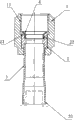
图1为本发明所提供实施例的剖视图。Fig. 1 is a cross-sectional view of an embodiment provided by the present invention.
图2为本发明所提供实施例的俯视图。Fig. 2 is a top view of the embodiment provided by the present invention.
具体实施方式 Detailed ways
参照附图1、2。With reference to accompanying
本实施例包括接头螺母1、接头芯2、连接在接头芯2一端的接管3,所述接头芯2在连接所述接管3的另一端设有垫片4,所述接头螺母1的内圈螺纹11上设有导气槽12,所述接管3和垫片4分别设在接头芯2的两端。This embodiment includes a
所述接头芯2在连接所述接管3的另一端还设有锥形口21,所述锥形口21的下部设有卡槽22,所述垫片4可嵌入所述锥形口21内,并卡接在所述卡槽22内。The
所述导气槽12的个数为四个,它们沿所述接头螺母1的内圈螺纹11周向均布,所述导气槽12的横截面呈倒“V”形。“V”形的导气槽在接头在折卸时,可以缓解管内压力,防止接头被管压压飞,引起安全事故。The number of the
所述接管3的出口端套入所述接头螺母1并具有伸出所述接头螺母1的外端32,所述外端32可在穿过所述接头螺母1之后进行扩大处理,所述外端32可被扩大。The outlet end of the connecting
所述接管3为铜管,所述垫片4为紫铜垫片。紫铜垫片嵌入接头芯内与接头芯的锥面相嵌于槽内,不易掉出,并且紫铜垫片比不锈钢材质软,二者配合,更利于密封。The connecting
接头螺母1可与外部管路直接通过螺纹配合相连接,操作方便。The
Claims (3)
Priority Applications (1)
| Application Number | Priority Date | Filing Date | Title |
|---|---|---|---|
| CN2010102167491A CN101893140B (en) | 2010-07-02 | 2010-07-02 | Fluid pipeline adapter substitute |
Applications Claiming Priority (1)
| Application Number | Priority Date | Filing Date | Title |
|---|---|---|---|
| CN2010102167491A CN101893140B (en) | 2010-07-02 | 2010-07-02 | Fluid pipeline adapter substitute |
Publications (2)
| Publication Number | Publication Date |
|---|---|
| CN101893140A CN101893140A (en) | 2010-11-24 |
| CN101893140B true CN101893140B (en) | 2012-09-12 |
Family
ID=43102422
Family Applications (1)
| Application Number | Title | Priority Date | Filing Date |
|---|---|---|---|
| CN2010102167491A Expired - Fee Related CN101893140B (en) | 2010-07-02 | 2010-07-02 | Fluid pipeline adapter substitute |
Country Status (1)
| Country | Link |
|---|---|
| CN (1) | CN101893140B (en) |
Citations (6)
| Publication number | Priority date | Publication date | Assignee | Title |
|---|---|---|---|---|
| GB1183580A (en) * | 1966-09-08 | 1970-03-11 | Atomic Energy Authority Uk | Improvements in or relating to Pipe Couplings |
| JPH07213640A (en) | 1994-02-01 | 1995-08-15 | Bosai Kikaku:Kk | Structure of un-winding piping for sprinkler |
| JPH07253182A (en) | 1994-03-15 | 1995-10-03 | Uetsukusu:Kk | Coupling device of plastic pipe such as copper pipe |
| CN2384086Y (en) * | 1999-07-02 | 2000-06-21 | 钟兴泉 | Pipe joint |
| JP2004340347A (en) * | 2003-03-14 | 2004-12-02 | Anzen Seikosha:Kk | Pipe joint seal mechanism |
| CN201507751U (en) * | 2009-06-04 | 2010-06-16 | 龚建清 | Connecting pipe fitting for pipeline |
-
2010
- 2010-07-02 CN CN2010102167491A patent/CN101893140B/en not_active Expired - Fee Related
Patent Citations (6)
| Publication number | Priority date | Publication date | Assignee | Title |
|---|---|---|---|---|
| GB1183580A (en) * | 1966-09-08 | 1970-03-11 | Atomic Energy Authority Uk | Improvements in or relating to Pipe Couplings |
| JPH07213640A (en) | 1994-02-01 | 1995-08-15 | Bosai Kikaku:Kk | Structure of un-winding piping for sprinkler |
| JPH07253182A (en) | 1994-03-15 | 1995-10-03 | Uetsukusu:Kk | Coupling device of plastic pipe such as copper pipe |
| CN2384086Y (en) * | 1999-07-02 | 2000-06-21 | 钟兴泉 | Pipe joint |
| JP2004340347A (en) * | 2003-03-14 | 2004-12-02 | Anzen Seikosha:Kk | Pipe joint seal mechanism |
| CN201507751U (en) * | 2009-06-04 | 2010-06-16 | 龚建清 | Connecting pipe fitting for pipeline |
Also Published As
| Publication number | Publication date |
|---|---|
| CN101893140A (en) | 2010-11-24 |
Similar Documents
| Publication | Publication Date | Title |
|---|---|---|
| CN201715135U (en) | Pipeline fast-repair thread casing joint | |
| CN201159349Y (en) | Hydraulic system pipe joint | |
| CN205781641U (en) | Pipeline coupling assembling and purifier | |
| CN101893140B (en) | Fluid pipeline adapter substitute | |
| CN202834533U (en) | Water-supply double-thread joint | |
| CN106641501A (en) | Petroleum pipe connection hoop | |
| CN202100863U (en) | Quick connector structure for rubber hoses | |
| CN208331488U (en) | A kind of pipe fitting reinforcement bindiny mechanism | |
| CN202580369U (en) | Fluid line adaptor | |
| CN105423011A (en) | Pipe joint | |
| CN207316279U (en) | A hydraulic system pipe joint | |
| CN205639993U (en) | Divide manifold | |
| CN203641720U (en) | Pipeline connecting piece | |
| CN205226705U (en) | Integrative soft pipe joint | |
| CN204284715U (en) | Hard tube pipe joint | |
| CN204004954U (en) | A kind of efficient air distributor test rapid pipe joint | |
| CN107676555A (en) | Hydraulic system pipe joint | |
| CN208381567U (en) | A kind of anticreep sealing converter | |
| CN205298888U (en) | Pipe -line system sealing joint | |
| CN208535390U (en) | A kind of multifunction conic pipe fitting joint | |
| CN205534768U (en) | Tee bend hose nipple | |
| CN203147104U (en) | Quick breakpoint pipe joint for oil pipe | |
| CN205479837U (en) | Connecting piece of nonrust steel pipe of quick installation | |
| CN217234775U (en) | Maintenance water hose press fitting | |
| CN201014092Y (en) | Flange type fast connecting tube articles |
Legal Events
| Date | Code | Title | Description |
|---|---|---|---|
| C06 | Publication | ||
| PB01 | Publication | ||
| C10 | Entry into substantive examination | ||
| SE01 | Entry into force of request for substantive examination | ||
| C14 | Grant of patent or utility model | ||
| GR01 | Patent grant | ||
| CF01 | Termination of patent right due to non-payment of annual fee |
Granted publication date: 20120912 |
|
| CF01 | Termination of patent right due to non-payment of annual fee |