CN101776152B - Outside pressurized type dynamic and static pressure gas lubricating and sealing device - Google Patents
Outside pressurized type dynamic and static pressure gas lubricating and sealing device Download PDFInfo
- Publication number
- CN101776152B CN101776152B CN 201010119546 CN201010119546A CN101776152B CN 101776152 B CN101776152 B CN 101776152B CN 201010119546 CN201010119546 CN 201010119546 CN 201010119546 A CN201010119546 A CN 201010119546A CN 101776152 B CN101776152 B CN 101776152B
- Authority
- CN
- China
- Prior art keywords
- pressure
- sealing
- static
- dynamic
- ring
- Prior art date
- Legal status (The legal status is an assumption and is not a legal conclusion. Google has not performed a legal analysis and makes no representation as to the accuracy of the status listed.)
- Expired - Fee Related
Links
Images


Landscapes
- Mechanical Sealing (AREA)
Abstract
一种外加压式动静压气体润滑密封装置,包括固定于动环座(1)上并随转轴旋转的动环(5),固定于密封腔体(2)和密封端盖(12)上的密封静环(11);在密封静环(11)内开有从外界引入外加压气体的通道(9),通道(9)以一定数量沿周向均匀分布在密封静环(11)内;通道(9)中设置有节流装置(8),在通道(9)的出口设置有一定深度的均压槽(7);动环(5)或密封静环(11)的端面上形成动压效应的多种动压槽(6),均压槽(7)的内侧和外侧均设有与其不连通的密封坝;通过调节外加压气体的压力实现在线监控。加压式动静压气体润滑密封大大降低了阻力矩,减小功耗,改进了传统的端面密封磨损严重的现象。
An externally pressurized dynamic and static pressure gas lubrication sealing device, including a moving ring (5) fixed on a moving ring seat (1) and rotating with a rotating shaft, fixed on a sealing cavity (2) and a sealing end cover (12) The static sealing ring (11); in the static sealing ring (11), there is a channel (9) for introducing the pressurized gas from the outside, and the channel (9) is uniformly distributed in the static sealing ring (11) in a certain number along the circumferential direction. inside; a throttling device (8) is set in the channel (9), and a pressure equalizing groove (7) of a certain depth is set at the outlet of the channel (9); the end face of the moving ring (5) or the sealing static ring (11) A variety of dynamic pressure grooves (6) forming a dynamic pressure effect, the inside and outside of the pressure equalizing groove (7) are provided with sealing dams that are not connected to them; online monitoring is realized by adjusting the pressure of externally pressurized gas. The pressurized dynamic and static pressure gas lubricated seal greatly reduces the resistance torque, reduces power consumption, and improves the serious wear and tear of the traditional end face seal.
Description
技术领域 technical field
本发明涉及到一种外加压式动静压气体润滑密封装置,适用于搅拌釜、压缩机、离心泵等旋转式流体机械的密封气体(或液体)的轴端密封,可应用于化工、食品、医药、航天、航空等行业。适用的转速范围很大,不仅可用于高达每分钟几万转的情况,也适用于转速很小或接近静止的情况,可用于双向运转。其适用的压力范围较大,也适用于压力波动的场合。适用于高低温各种工况。The invention relates to an externally pressurized dynamic and static pressure gas lubrication and sealing device, which is suitable for the shaft end sealing of the sealing gas (or liquid) of rotary fluid machines such as stirring tanks, compressors, centrifugal pumps, etc., and can be used in chemical industry, food , medicine, aerospace, aviation and other industries. The applicable speed range is very large, not only for tens of thousands of revolutions per minute, but also for small or near-stationary situations, and can be used for bidirectional operation. Its applicable pressure range is large, and it is also suitable for occasions with pressure fluctuations. Suitable for various working conditions of high and low temperature.
背景技术 Background technique
长期以来,密封装置被认为是旋转流体机械最大的难点,是其发生故障的主要原因。这就引起了对旋转密封装置的广泛研究,进而出现了各种各样的密封形式,其重要的一种密封型式是微槽面气体动压密封即干气密封,并得到了广泛的应用。干气密封具有较多的优点:运行稳定、可靠、易操作,辅助系统少,大大降低了操作人员维护的工作量;密封消耗的只是气体,既节能又环保,泄漏量少、磨损小、能耗低,被密封的流体不受油污染。干气密封是一种径向流体动压式机械密封,是非接触式机械密封中一种新发展起来的密封装置。它是在机械密封的动环或静环的密封端面上开有微槽,当动环高速旋转时,被密封气体在微槽和围堰的作用下在动静环之间形成几微米的气膜。该气膜具有一定刚度,将动静环推开,使两密封端面不接触,也阻止密封气体的外漏。气体润滑密封的一大特点就是需要动环高速旋转才能产生所需要的开启力,这一特点一直制约着气体润滑密封的广泛使用。在一些生产过程中,特别是食品、医药行业,流体机械的工况总是在不停地变化,变工况对密封的影响是很大的。当干气密封装置在非设计工况下工作时,会引起密封状态的变化,使得普通干气密封从全气体润滑密封过渡为边界润滑密封,甚至无润滑介质密封状态,而且旋转流体机械开停机阶段,转速也比较低,密封动静环之间形成的动压力也很低,动、静环往往是接触摩擦状态,所以采用干气密封的旋转机械,不能低速下长期运转。For a long time, the sealing device has been considered as the biggest difficulty of rotary fluid machinery and the main cause of its failure. This has led to extensive research on rotary sealing devices, and various sealing forms have emerged. An important sealing type is micro-groove surface gas dynamic pressure seal, that is, dry gas seal, and has been widely used. Dry gas seals have many advantages: stable, reliable, easy to operate, less auxiliary systems, greatly reducing the maintenance workload of operators; the seal consumes only gas, which is energy-saving and environmentally friendly, with less leakage, less wear, and energy saving. The consumption is low, and the sealed fluid is not polluted by oil. The dry gas seal is a radial fluid dynamic mechanical seal and a newly developed sealing device in the non-contact mechanical seal. It is a micro-groove on the sealing end surface of the moving ring or static ring of the mechanical seal. When the moving ring rotates at a high speed, the sealed gas forms a few micron gas film between the moving and static rings under the action of the micro-groove and cofferdam. . The gas film has a certain rigidity, and pushes the dynamic and static rings apart, so that the two sealing end faces do not touch, and also prevents the leakage of the sealing gas. A major feature of gas-lubricated seals is that the high-speed rotation of the moving ring is required to generate the required opening force. This feature has always restricted the widespread use of gas-lubricated seals. In some production processes, especially in the food and pharmaceutical industries, the working conditions of fluid machinery are always changing, and the changing working conditions have a great impact on the seal. When the dry gas seal device works under non-design conditions, it will cause changes in the sealing state, making the ordinary dry gas seal transition from a full gas lubricated seal to a boundary lubricated seal, or even a non-lubricating medium seal state, and the rotating fluid machinery starts and stops stage, the rotational speed is also relatively low, and the dynamic pressure formed between the sealed dynamic and static rings is also very low. The dynamic and static rings are often in a state of contact friction, so rotating machinery with dry gas seals cannot operate at low speed for a long time.
静压密封仅利用密封的静压效应来形成液膜或气膜,主要有自加压静压密封和外加压静压密封。自加压静压密封主要用于流体自身的压力,外加压静压密封需要外部液压源或气压源。静压密封仅利用流体的静压力而未利用旋转的动压力,其在泄漏量的控制和密封的稳定性上还有些问题需要解决。The static pressure seal only uses the static pressure effect of the seal to form a liquid film or a gas film, mainly including self-pressurized static pressure seals and externally applied static pressure seals. The self-pressurized hydrostatic seal is mainly used for the pressure of the fluid itself, and the externally pressurized hydrostatic seal requires an external hydraulic or air source. The static pressure seal only utilizes the static pressure of the fluid instead of the dynamic pressure of the rotation, and there are still some problems to be solved in the control of leakage and the stability of the seal.
发明内容 Contents of the invention
本发明的目的在于,通过提供一种外加压式动静压气体润滑密封装置,以更好地解决单一的静压或动压密封存在的问题,实现流体动静压密封优势的互补。The purpose of the present invention is to better solve the problems of single static pressure or dynamic pressure sealing by providing an externally pressurized dynamic and static pressure gas lubrication sealing device, and realize the complementary advantages of fluid dynamic and static pressure sealing.
本发明是采用以下技术手段实现的:The present invention is realized by adopting the following technical means:
一种外加压式动静压气体润滑密封装置,包括固定于动环座上并随转轴旋转的动环,固定于密封腔体和密封端盖的密封静环;在密封静环内开有从外界引入外加压气体的通道,通道以一定数量均匀分布在密封静环内;通道中设置有节流装置,在通道的出口设置有一定深度的均压槽;动环或密封静环的端面上形成动压效应的多种动压槽,均压槽的内侧和外侧均设有与其不连通的密封坝;通过调节外加压气体的压力实现在线监控。An externally pressurized dynamic and static pressure gas lubrication sealing device, including a moving ring fixed on a moving ring seat and rotating with a rotating shaft, a sealing static ring fixed to a sealing cavity and a sealing end cover; The channel for the external pressurized gas is introduced from the outside, and a certain number of channels are evenly distributed in the sealed static ring; a throttling device is arranged in the channel, and a pressure equalizing groove of a certain depth is provided at the outlet of the channel; the end face of the moving ring or the sealed static ring A variety of dynamic pressure grooves that form a dynamic pressure effect on the surface, and the inner and outer sides of the pressure equalizing groove are provided with sealing dams that are not connected to it; online monitoring is realized by adjusting the pressure of the externally pressurized gas.
前述的外加压气体的压力高于被密封介质的压力0.15~0.45MPa。The pressure of the aforementioned external pressurized gas is 0.15-0.45 MPa higher than the pressure of the sealed medium.
前述的密封静环如不能轴向补偿,通过密封腔体与密封静环外径和两个O形密封圈形成的环形空间将外加气体引入到密封端面间;如密封静环具有轴向补偿能力时,通过柔性管道或螺旋环管将外加压气体引入到密封端面间。If the aforementioned static sealing ring cannot be axially compensated, the external gas is introduced into the sealing end faces through the annular space formed by the sealing cavity, the outer diameter of the static sealing ring and the two O-rings; if the static sealing ring has axial compensation capability When , the external pressurized gas is introduced between the sealing end faces through a flexible pipe or a spiral ring pipe.
前述的密封静环内开有一定数量沿周向均布的通道,通道中设置的节流装置为节流孔。A certain number of passages uniformly distributed along the circumferential direction are opened in the aforementioned static sealing ring, and the throttling devices arranged in the passages are throttling holes.
在密封静环端面外加压气体出口处开有一定宽度和深度的环形均压槽。An annular pressure equalizing groove with a certain width and depth is opened at the outlet of pressurized gas outside the end face of the sealing stationary ring.
前述的动环或密封静环密封端面上开有动压槽,动压槽以一定数量沿周向均匀分布在密封环端面上。There are dynamic pressure grooves on the sealing end surface of the aforementioned moving ring or sealing static ring, and a certain number of dynamic pressure grooves are evenly distributed on the end surface of the sealing ring along the circumferential direction.
前述的动压槽形状可以是螺旋槽、圆弧槽、燕尾槽、T型槽。The aforementioned shape of the dynamic pressure groove may be a spiral groove, an arc groove, a dovetail groove, or a T-shaped groove.
前述的动压槽的位置如下:在密封静环或动环的最外侧和最内侧同时布置或仅在最外侧或最内侧布置;与环形均压槽内侧和外侧同时布置或单侧布置,并与环形均压槽连通。The position of the aforementioned dynamic pressure groove is as follows: it is arranged at the outermost and innermost of the sealing static ring or moving ring at the same time or only at the outermost or innermost; it is arranged at the same time as the inner and outer sides of the annular pressure equalizing groove or on one side, and It communicates with the annular pressure equalizing groove.
前述的环形均压槽内侧或外侧都有与外径或内径不相通的密封坝。The inside or outside of the aforementioned annular pressure equalizing groove has a sealing dam that is not connected to the outer diameter or the inner diameter.
前述的在线监控,可采用信号控制,也可采用比例控制阀根据密封介质压力控制。The aforementioned on-line monitoring can be controlled by signals, or controlled by proportional control valves according to the pressure of the sealing medium.
本发明一种外加压式动静压气体润滑密封装置,与现有技术相比,具有以下明显的优势和有益效果:Compared with the prior art, an externally pressurized dynamic and static pressure gas lubrication and sealing device of the present invention has the following obvious advantages and beneficial effects:
外加压式动静压气体混合润滑密封是一种同时利用气体静压和动压效应的非接触密封,以其特有的高低速度适应性、可双向旋转以及在线可调控能力,克服了单纯的静压气体润滑或动压气体润滑密封的一些不足。本发明的外加压式动静压气体润滑密封,包括常用的旋转端面密封的动环和静环,采取在动静环上设置引入外加压气体的带有节流装置的通道,通过出口设置均压槽,及在密封环端面加工微槽的方式实现动静压的结合,提高密封能力,减小摩擦磨损,扩大密封使用范围。The external pressure dynamic and static pressure gas mixed lubrication seal is a non-contact seal that utilizes the effects of gas static pressure and dynamic pressure at the same time. With its unique high and low speed adaptability, bidirectional rotation and online adjustable ability, it overcomes the simple static Some deficiencies of compressed gas lubrication or dynamic pressure gas lubricated seals. The externally pressurized dynamic and static pressure gas lubrication seal of the present invention includes the commonly used rotary end face seal dynamic ring and static ring, adopts a channel with a throttling device for introducing externally pressurized gas on the dynamic and static ring, and sets a uniform flow through the outlet. Pressure grooves, and the way of processing micro grooves on the end face of the sealing ring realize the combination of dynamic and static pressure, improve the sealing ability, reduce friction and wear, and expand the application range of the seal.
通常情况下,密封环外侧的流体是高压区,内侧为低压区,在压力的作用下在密封动静环密封端面间形成一层气膜,以减小密封动静环之间的摩擦和磨损,该气膜对于旋转密封的密封能力是有很大影响的。前人通过很多例如改进结构、开槽等方式来改善该气膜以提高密封能力。本发明在两个相对旋转的动静密封环端面间引入高于被密封气体的外加压气体,如空气或氮气。为了达到减小泄漏控制气体流量的目的,外加压气体经过节流装置,如小孔节流,进入到密封的动静环端面间的均压槽内。均压槽为几十到几百微米左右的环向槽,其作用在于使小孔后的压力在密封端面间均匀分布,同时均压槽也起到节流,减小泄漏的作用。经小孔节流后,外加压气体的压力下降,通过均压槽向密封介质侧和大气侧流动。同时密封端面的均压槽两侧上设置微米级动压槽,动压槽起到改变端面开启力和密封泄漏特性。这样在密封动、静环两端面就依靠流体静压和动压效应形成了一层微米级的气膜,将密封动静环隔开,形成非接触密封。密封的开启力由这层气膜提供,闭合力由弹簧力和被密封介质压力提供。外加压式动静压气体润滑密封大大降低了阻力矩,减小功耗,改进了传统的端面密封磨损严重的现象。Normally, the fluid outside the sealing ring is a high-pressure area, and the inner side is a low-pressure area. Under the action of pressure, a layer of gas film is formed between the sealing end faces of the sealing dynamic and static rings to reduce friction and wear between the sealing dynamic and static rings. The air film has a great influence on the sealing ability of the rotary seal. The predecessors have improved the air film through many methods such as improving the structure and slotting to improve the sealing ability. The present invention introduces an external pressurized gas higher than the sealed gas, such as air or nitrogen, between the end faces of two relatively rotating dynamic and static sealing rings. In order to achieve the purpose of reducing leakage and controlling gas flow, the externally pressurized gas passes through a throttling device, such as a small hole throttling, and enters the pressure equalizing groove between the end faces of the sealed dynamic and static rings. The pressure equalizing groove is a circumferential groove of tens to hundreds of microns. Its function is to make the pressure behind the small hole evenly distributed between the sealing end faces. At the same time, the pressure equalizing groove also plays the role of throttling and reducing leakage. After throttling through the small hole, the pressure of the externally pressurized gas drops, and flows to the sealing medium side and the atmosphere side through the pressure equalizing groove. At the same time, micron-scale dynamic pressure grooves are arranged on both sides of the pressure equalizing groove on the sealing end face, and the dynamic pressure grooves can change the opening force of the end face and the sealing leakage characteristics. In this way, a layer of micron-sized air film is formed on the two ends of the sealing dynamic and static rings by virtue of hydrostatic pressure and dynamic pressure effects, separating the sealing dynamic and static rings to form a non-contact seal. The opening force of the seal is provided by this layer of air film, and the closing force is provided by the spring force and the pressure of the sealed medium. The external pressure dynamic and static pressure gas lubricated seal greatly reduces the resistance torque, reduces power consumption, and improves the serious wear and tear phenomenon of the traditional end face seal.
外加压式动静压气体润滑密封,需要把外加压气体引入到密封端面之间,外加压气体的压力高于被密封介质的压力0.15~0.45MPa。若被密封介质压力不波动,则可采用固定外加压力源的方法;若被密封介质压力波动或经常变化,可以根据被密封介质压力手动调节外加压气体的压力或采用比例调节阀根据被密封介质压力自动设定外加压气体的压力。The externally pressurized dynamic and static pressure gas lubrication seal needs to introduce the externally pressurized gas between the sealing end faces, and the pressure of the externally pressurized gas is 0.15-0.45MPa higher than the pressure of the sealed medium. If the pressure of the sealed medium does not fluctuate, the method of fixing the external pressure source can be adopted; if the pressure of the sealed medium fluctuates or changes frequently, the pressure of the external pressurized gas can be manually adjusted according to the pressure of the sealed medium or a proportional regulating valve can be used according to the pressure of the sealed medium. The medium pressure automatically sets the pressure of the external pressurized gas.
附图说明 Description of drawings
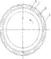
图1是补偿机构旋转的外加压式动静压气体润滑密封中动环和静环端面示意图;Figure 1 is a schematic diagram of the end faces of the moving ring and the static ring in the externally pressurized dynamic and static pressure gas lubricated seal where the compensation mechanism rotates;
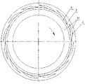
图2是补偿机构静止的外加压式动静压气体润滑密封中动环和静环端面的示意图;Fig. 2 is a schematic diagram of the end faces of the moving ring and the static ring in the static externally pressurized dynamic and static pressure gas lubrication seal of the compensating mechanism;
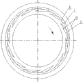
图3是密封环端面双吸入式结构示意图;Fig. 3 is a schematic diagram of a double-suction structure on the end face of the sealing ring;
图4是密封环端面双泵出式结构示意图;Fig. 4 is a schematic diagram of a double-pump-out structure on the end face of the sealing ring;
图5是密封环端面外侧吸入式结构示意图;Fig. 5 is a schematic diagram of the suction structure outside the end face of the sealing ring;
图6是密封环端面外侧泵出式结构示意图;Fig. 6 is a schematic diagram of a pump-out structure outside the end face of the sealing ring;
图7是密封环端面内侧吸入式结构示意图;Fig. 7 is a schematic diagram of the suction structure inside the end face of the sealing ring;
图8是密封环端面内侧泵出式结构示意图。Fig. 8 is a schematic diagram of a pump-out type structure inside the end face of the sealing ring.
具体实施方式 Detailed ways
以下结合附图所示实施的具体实施方式,对本发明内容再做进一步的详细说明。The content of the present invention will be further described in detail below in conjunction with the specific implementation manners shown in the accompanying drawings.
请参阅图1、图2所示,将外加压气体引入到密封端面间的方式可为图1所示,密封静环不能轴向补偿,静止不动的情况下通过密封腔体2与密封静环11外径和两个O形密封圈10形成的环形空间引入到密封端面间。当静环具有轴向补偿能力时,即弹簧3静止不旋转,可通过柔性管道15或螺旋环管引入到密封端面间,如图2所示。Please refer to Figure 1 and Figure 2. The way to introduce the external pressurized gas between the sealing end faces can be shown in Figure 1. The static ring of the seal cannot compensate axially. The annular space formed by the outer diameter of the static ring 11 and the two O-rings 10 is introduced between the sealing end faces. When the static ring has axial compensation capability, that is, the spring 3 is stationary and does not rotate, it can be introduced between the sealing end faces through a flexible pipe 15 or a spiral ring pipe, as shown in FIG. 2 .
在静环中引入外加压气体的流体通道上设置节流装置,如小孔节流。节流孔数对泄漏量的影响较大,但对开启力的影响较小。这是因为均压槽的存在,使压力分布较均匀,节流孔数量变化时,压力分布变化不明显,所以节流孔数对开启力的影响较小;但更多的节流孔提供更多的气体流入密封端面间地通道,所以泄漏量增加较多。因此,为了控制加工成本,静压气体密封可以采用较少地节流孔,达到所需要的开启力,保持较小地泄漏量并具有较大地刚度,节流孔数量一般4~12个为佳。A throttling device, such as a small hole throttling, is arranged on the fluid passage introducing the externally pressurized gas in the static ring. The number of orifices has a greater influence on the leakage, but less on the opening force. This is because the existence of the pressure equalizing groove makes the pressure distribution more uniform. When the number of orifices changes, the pressure distribution does not change significantly, so the number of orifices has little effect on the opening force; but more orifices provide more More gas flows into the passage between the sealing end faces, so the leakage increases more. Therefore, in order to control the processing cost, the static pressure gas seal can use fewer orifices to achieve the required opening force, maintain a small leakage and have greater rigidity. The number of orifices is generally 4 to 12. .
同时,本发明密封装置在密封静环外加压气体引入通道出口设置均压槽。均压槽的主要作用是沿周向均匀地分布通道出口的压力,并起到二次节流的作用。无均压槽的静压气体密封泄漏量比有均压槽的泄漏量要大,膜厚增加时,两种结构泄漏量的差值更大,说明均压槽具有再次节流的作用,可以有效地降低泄漏量,这对静压气体密封是相当有利的。At the same time, the sealing device of the present invention is provided with a pressure equalizing groove at the outlet of the pressurized gas introduction channel outside the sealing static ring. The main function of the pressure equalizing groove is to evenly distribute the pressure at the outlet of the channel along the circumferential direction, and play the role of secondary throttling. The leakage of the static pressure gas seal without pressure equalization groove is larger than that with pressure equalization groove. When the film thickness increases, the difference in leakage between the two structures is larger, indicating that the pressure equalization groove has the function of throttling again and can Effectively reduce leakage, which is quite beneficial for static pressure gas sealing.
在动环5或是密封静环11密封端面上开有微米级动压槽6,动压槽形状可以是螺旋槽、圆弧槽、燕尾槽、T型槽等不同的槽形。动压槽的主要作用是利用旋转轴的旋转动能来产生动压效应。通过设置不同的动压槽形式,密封可以达到不同的效果,以控制泄漏,增加密封稳定性,如图3为双吸入式,可减少外加压气体的泄漏量;图4为双泵出式,可增加外加压的泄漏量,方便测量和控制,同时增加密封的开启力;图5为外侧吸入式,可减少外加压气体向被密封介质的泄漏量;图6为外侧泵出式,可增加外加压气体向被密封介质的泄漏量,减少被密封介质向外侧泄漏的可能性,同时开启力有增加;图7为内侧吸入式,可减少空气侧的总泄漏量;图8为内侧泵出式,可增加向大气侧的泄漏量,同时开启力有增加;There is a micron-scale
密封端面上均压槽内侧或外侧都有与内径和外径不相通的密封坝。这样可保证密封工作时泄漏量小,密封坝起到节流的作用;同时密封静止状态下,若外加压气体压力为零时,保证被密封介质不泄漏到大气中。There are sealing dams not connected to the inner diameter and the outer diameter on the inner side or the outer side of the pressure equalizing groove on the sealing end face. This can ensure that the leakage is small when the seal is in operation, and the seal dam plays the role of throttling; at the same time, in the static state of the seal, if the pressure of the external pressurized gas is zero, it is ensured that the sealed medium does not leak into the atmosphere.
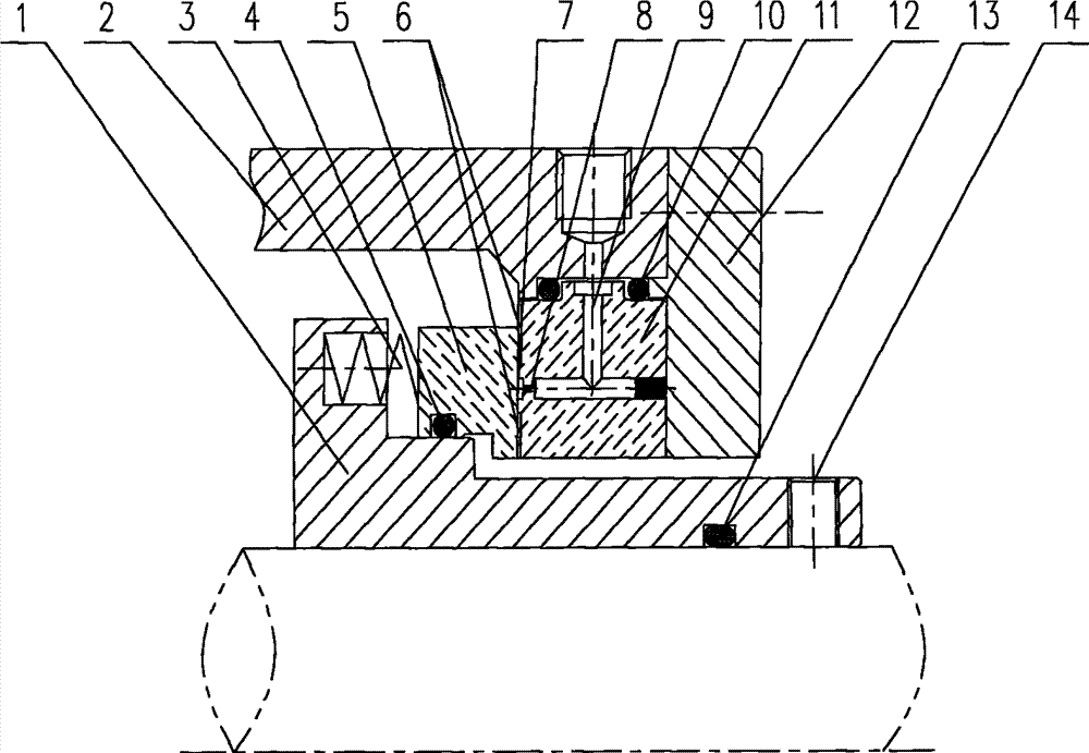
通过在线监测密封状态,调节外加压气体的压力以达到更好的动静压润滑密封效果。在线可调控。可采用信号控制,也可采用比例控制阀根据密封介质压力控制如图1所示为补偿机械旋转的外加压动静压压气体混合润滑密封装置的结构,包括采用两个O形密封圈10固连于腔体2和密封压盖12的密封静环11,和经O形密封圈4与旋转轴或轴套等旋转体单元1连接而随之转动的动环5,轴套与轴之间采用O形密封圈13密封,并用顶丝14传动,弹簧3安装于轴套1和密封动环5之间,用于产生部分闭合力。在静环11的径向内外两侧密封面上,设置有不同形式的流体动压槽6;在静环11中间部分的密封面上,设置有流体均压槽7和节流孔8。By monitoring the sealing state online, the pressure of the external pressurized gas can be adjusted to achieve a better dynamic and static pressure lubrication and sealing effect. Adjustable online. It can be controlled by signal, or by proportional control valve according to the pressure of the sealing medium. As shown in Figure 1, the structure of the mixed lubrication sealing device with external pressure, dynamic and static pressure, and gas for compensating mechanical rotation includes two O-shaped sealing rings 10 solid The sealing static ring 11 connected to the cavity 2 and the sealing gland 12, and the moving ring 5 which is connected to the
图2所示的是补偿机构静止的外加压动静压气体混合润滑密封装置的结构,包括有经柔性接管15和O形密封圈4固连于密封压盖12和密封腔体2的静环11和,经O形密封圈10与旋转轴套1连接而能随之转动的动环5。轴套与旋转轴之间采用O形密封圈13密封,采用顶丝14传动。静环11后侧安装有弹簧3,与密封压盖之间采用O形密封圈4密封。在静环11的径向内外两侧密封面上,设置有不同形式的流体动压槽6,在静环11中间部分的密封面上,设置有流体均压槽7和节流孔8,内部设置引入外加压气体的通道9。Figure 2 shows the structure of the static external pressure dynamic and static pressure gas mixed lubrication sealing device of the compensation mechanism, including a static ring that is fixedly connected to the sealing gland 12 and the sealing cavity 2 through a flexible joint 15 and an O-ring 4 11 and the moving ring 5 that is connected with the
图3~图8所示的是多种密封端面的结构形式,分别为图3为双吸入式、图4为双泵出式、图5为外侧吸入式、图6为外侧泵出式、图7为内侧吸入式、图8为内侧泵出式等。均压槽7的位置设置在密封端面中间附近,宽度为1~4mm可根据密封面宽度进行选择,深度为5μm~800μm选择,太浅加工困难,太深对密封的高速动态性影响较坏。静环上的节流孔8数量一般为4~12个,节流孔直径一般在0.1~0.6mm范围内选择,长度为1~5mm左右,位置在密封端面的中间附近。动压槽6的个数为8~20个左右,布置的方式除了图3~图8所给出的方式外,为了不同的目的还可以由图4~图7组合而成,动压槽深度为3~9μm左右。动压槽6不应直接连通均压槽7和密封环的内径或外径,之间应有不连通的密封坝16。在正常工作状态下,动、静环端面间要保持合适的液膜厚度2~10μm。Figures 3 to 8 show the structural forms of various sealing end faces, respectively, Figure 3 is the double suction type, Figure 4 is the double pumping type, Figure 5 is the outer suction type, Figure 6 is the outer pumping type, and Figure 6 is the outer pumping type. 7 is an inside suction type, and Fig. 8 is an inside pump out type, etc. The position of
Claims (4)
Priority Applications (1)
| Application Number | Priority Date | Filing Date | Title |
|---|---|---|---|
| CN 201010119546 CN101776152B (en) | 2010-03-05 | 2010-03-05 | Outside pressurized type dynamic and static pressure gas lubricating and sealing device |
Applications Claiming Priority (1)
| Application Number | Priority Date | Filing Date | Title |
|---|---|---|---|
| CN 201010119546 CN101776152B (en) | 2010-03-05 | 2010-03-05 | Outside pressurized type dynamic and static pressure gas lubricating and sealing device |
Publications (2)
| Publication Number | Publication Date |
|---|---|
| CN101776152A CN101776152A (en) | 2010-07-14 |
| CN101776152B true CN101776152B (en) | 2013-08-21 |
Family
ID=42512693
Family Applications (1)
| Application Number | Title | Priority Date | Filing Date |
|---|---|---|---|
| CN 201010119546 Expired - Fee Related CN101776152B (en) | 2010-03-05 | 2010-03-05 | Outside pressurized type dynamic and static pressure gas lubricating and sealing device |
Country Status (1)
| Country | Link |
|---|---|
| CN (1) | CN101776152B (en) |
Families Citing this family (53)
| Publication number | Priority date | Publication date | Assignee | Title |
|---|---|---|---|---|
| CN102242810B (en) * | 2011-04-14 | 2013-10-16 | 北京化工大学 | Continuous injection-ejection centrifugal seal device and gas-liquid control system thereof |
| CN102278482A (en) * | 2011-06-23 | 2011-12-14 | 北京化工大学 | Mechanical seal device with stress self adaption |
| CN104520616B (en) * | 2012-12-25 | 2016-08-24 | 伊格尔工业股份有限公司 | Slide unit |
| CN103133697B (en) * | 2013-02-26 | 2015-11-25 | 浙江工业大学 | Can the dovetail groove end surface mechanical sealing structure of bidirectional rotation |
| CN103234045A (en) * | 2013-04-13 | 2013-08-07 | 丹东克隆集团有限责任公司 | Balanced spring mechanical seal for pumps |
| CN203784293U (en) * | 2014-01-26 | 2014-08-20 | 清华大学 | Mechanical sealing device |
| CN104019051B (en) * | 2014-04-29 | 2017-01-18 | 北京化工大学 | Adjustable balance disk seal of centrifugal compressor |
| CN104235380A (en) * | 2014-08-29 | 2014-12-24 | 江苏大学 | Mechanical seal with two-stage staggered hydrodynamic grooves |
| CN104235381A (en) * | 2014-08-29 | 2014-12-24 | 江苏大学 | Dynamic and static pressure combined mechanical seal structure with liquid storage tanks |
| DE102015226444A1 (en) * | 2015-12-22 | 2017-06-22 | Eagleburgmann Germany Gmbh & Co. Kg | Mechanical seal assembly for sealing critical media |
| CN106089692A (en) * | 2016-07-01 | 2016-11-09 | 魏宇坤 | A kind of cryogenic liquid pump self-lubricating contact device and method |
| CN106015579B (en) * | 2016-07-15 | 2018-08-28 | 清华大学 | A kind of mechanically-sealing apparatus based on throttle structure active control |
| CN106246582B (en) * | 2016-07-21 | 2018-05-11 | 北京化工大学 | Rotary compressor abnormality self-cure regulation and control system and method |
| WO2018014286A1 (en) * | 2016-07-21 | 2018-01-25 | 北京化工大学 | Regulation and control system and method for self-healing of rotary compressor in abnormal state |
| CN106545523B (en) * | 2016-10-28 | 2019-05-31 | 沈阳透平机械股份有限公司 | End cover structure and processing method for preventing leakage of working gas of vertically split compressor |
| CN107061346B (en) * | 2017-05-08 | 2024-03-08 | 东莞鸿凯工程设备有限公司 | Mechanical seal structure and circulating pump |
| CN107701501A (en) * | 2017-09-25 | 2018-02-16 | 襄阳五二五泵业有限公司 | A kind of pump shaft seal structure with wearing clearance compensation |
| JP7210566B2 (en) * | 2018-05-17 | 2023-01-23 | イーグル工業株式会社 | Seal ring |
| DE102018208519A1 (en) * | 2018-05-29 | 2019-12-05 | Eagleburgmann Germany Gmbh & Co. Kg | Mechanical seal assembly for zero emission |
| CN108692031B (en) * | 2018-06-01 | 2024-08-23 | 大连久泰密封有限公司 | Dry gas seal friction pair |
| WO2020027102A1 (en) | 2018-08-01 | 2020-02-06 | イーグル工業株式会社 | Slide component |
| CN112424514B (en) | 2018-08-24 | 2023-04-28 | 伊格尔工业股份有限公司 | Sliding member |
| US10883483B2 (en) * | 2018-09-28 | 2021-01-05 | Air Products And Chemicals, Inc. | Seal assembly for reciprocating compressor |
| CN116025714B (en) | 2018-10-01 | 2026-03-27 | 伊格尔工业股份有限公司 | sliding parts |
| CN112789434B (en) | 2018-10-24 | 2023-09-29 | 伊格尔工业股份有限公司 | sliding parts |
| EP3889474A4 (en) | 2018-11-30 | 2022-08-10 | Eagle Industry Co., Ltd. | Sliding component |
| KR102541901B1 (en) | 2018-12-21 | 2023-06-13 | 이구루코교 가부시기가이샤 | sliding parts |
| CN109611374A (en) * | 2019-01-14 | 2019-04-12 | 北京星际荣耀空间科技有限公司 | Sandwich labyrinth seal structure for turbo pump of cryogenic liquid rocket engine |
| CN113260797B (en) | 2019-02-04 | 2023-02-14 | 伊格尔工业股份有限公司 | sliding parts |
| US11933405B2 (en) | 2019-02-14 | 2024-03-19 | Eagle Industry Co., Ltd. | Sliding component |
| EP4317728B1 (en) | 2019-02-21 | 2026-01-14 | Eagle Industry Co., Ltd. | Sliding components |
| CN110274026B (en) * | 2019-06-28 | 2021-06-22 | 中国航空工业集团公司北京长城计量测试技术研究所 | An air curtain type end face sealing device |
| JP7399966B2 (en) | 2019-07-26 | 2023-12-18 | イーグル工業株式会社 | sliding parts |
| CN110566794B (en) * | 2019-09-09 | 2020-12-08 | 珠海格力节能环保制冷技术研究中心有限公司 | Lubricating structure and mechanical lubricating device with same |
| CN111237469A (en) * | 2020-03-06 | 2020-06-05 | 上海好米密封科技有限公司 | Fluid dynamic pressure type postposition isolation sealing device for dry gas sealing of turbine machinery |
| CN111188653B (en) * | 2020-03-06 | 2024-07-05 | 上海优赛密封科技有限公司 | Gas lubrication dynamic pressure sealing device for miniature high-speed turbine expander |
| KR20250116162A (en) | 2020-06-02 | 2025-07-31 | 이구루코교 가부시기가이샤 | Sliding component |
| US12276338B2 (en) | 2020-06-02 | 2025-04-15 | Eagle Industry Co., Ltd. | Sliding component |
| CN112096874B (en) * | 2020-08-31 | 2022-11-08 | 东台市光明机械密封有限公司 | A kind of high wear-resistant double-end mechanical seal and its processing technology |
| CN112096879A (en) * | 2020-09-30 | 2020-12-18 | 北京化工大学 | Monitoring type dynamic pressure sealing device and method for monitoring opening and closing states of sealing end faces |
| CN112628293A (en) * | 2020-11-16 | 2021-04-09 | 中国航发西安动力控制科技有限公司 | Combined shaft seal structure for hydraulic pump motor |
| JP7608033B2 (en) | 2021-03-12 | 2025-01-06 | イーグル工業株式会社 | Sliding parts |
| CN113090338A (en) * | 2021-05-10 | 2021-07-09 | 西安热工研究院有限公司 | Reverse-rotation-direction thread opposite-impact type air seal structure and air seal method for carbon dioxide turbine |
| EP4372253A4 (en) | 2021-07-13 | 2025-07-16 | Eagle Ind Co Ltd | SLIDING COMPONENTS |
| EP4411182A4 (en) | 2021-09-28 | 2025-09-17 | Eagle Ind Co Ltd | Sliding component |
| CN114135673B (en) * | 2021-09-29 | 2024-07-19 | 浙江工业大学 | Vacuum suction type dry gas sealing structure based on Bernoulli principle |
| CN114251374B (en) * | 2021-12-31 | 2024-06-07 | 昆山顺之晟精密机械有限公司 | Annular wire cutting bearing seat |
| CN114198502B (en) * | 2022-01-04 | 2024-03-19 | 昆明理工大学 | A built-in polytetrafluoroethylene static pressure dry gas sealing ring for battery ternary material mixing equipment and its preparation method and application |
| CN114857275B (en) * | 2022-05-13 | 2025-09-09 | 成都一通密封股份有限公司 | A hybrid dry gas seal structure |
| CN115306902A (en) * | 2022-08-09 | 2022-11-08 | 昆明理工大学 | Static pressure dry gas sealing device based on slit throttling principle |
| CN116201900A (en) * | 2023-01-04 | 2023-06-02 | 昆明理工大学 | Dry gas sealing ring with crescent-like fin-shaped fluid grooves reversely arranged |
| CN119288906B (en) * | 2024-12-01 | 2025-04-08 | 驭磁智汇驱动科技(青岛)有限公司 | Dynamic pressure sealing device of air compressor impeller |
| CN119982901B (en) * | 2025-04-03 | 2025-10-17 | 昆明理工大学 | Star-shaped linear dynamic pressure groove-back pressure self-drainage reinforced pressurizing dry gas sealing structure |
Citations (4)
| Publication number | Priority date | Publication date | Assignee | Title |
|---|---|---|---|---|
| US3917289A (en) * | 1971-07-30 | 1975-11-04 | Ivanov Viktor V | Mechanical seal |
| DE3116283A1 (en) * | 1981-04-24 | 1982-11-11 | Lederle GmbH Pumpen- und Maschinenfabrik, 7803 Gundelfingen | Rotary piston pump with a face seal |
| CN2432391Y (en) * | 2000-06-13 | 2001-05-30 | 石油大学(华东) | Linear fluid dynamic channel upstream pumping machine seal |
| CN101057093A (en) * | 2004-11-09 | 2007-10-17 | 伊格尔工业股份有限公司 | mechanical seal |
Family Cites Families (1)
| Publication number | Priority date | Publication date | Assignee | Title |
|---|---|---|---|---|
| JPH09273636A (en) * | 1996-04-05 | 1997-10-21 | Mitsubishi Heavy Ind Ltd | Mechanical seal |
-
2010
- 2010-03-05 CN CN 201010119546 patent/CN101776152B/en not_active Expired - Fee Related
Patent Citations (4)
| Publication number | Priority date | Publication date | Assignee | Title |
|---|---|---|---|---|
| US3917289A (en) * | 1971-07-30 | 1975-11-04 | Ivanov Viktor V | Mechanical seal |
| DE3116283A1 (en) * | 1981-04-24 | 1982-11-11 | Lederle GmbH Pumpen- und Maschinenfabrik, 7803 Gundelfingen | Rotary piston pump with a face seal |
| CN2432391Y (en) * | 2000-06-13 | 2001-05-30 | 石油大学(华东) | Linear fluid dynamic channel upstream pumping machine seal |
| CN101057093A (en) * | 2004-11-09 | 2007-10-17 | 伊格尔工业股份有限公司 | mechanical seal |
Also Published As
| Publication number | Publication date |
|---|---|
| CN101776152A (en) | 2010-07-14 |
Similar Documents
| Publication | Publication Date | Title |
|---|---|---|
| CN101776152B (en) | Outside pressurized type dynamic and static pressure gas lubricating and sealing device | |
| CN104019237B (en) | Deep trouth annulus dynamic pressure type end surface mechanical sealing structure | |
| CN104896104B (en) | A kind of online adjustable gas lubrication mechanically-sealing apparatus of closing force | |
| CN106122484B (en) | Built-in sealing medium throttling regulation and control device for dynamic and static pressure type dry gas seal | |
| CN203784293U (en) | Mechanical sealing device | |
| CN204692588U (en) | The gas lubrication mechanical seal device that a kind of closing force is adjustable online | |
| WO2014190825A1 (en) | Pump-conveyed fluid dynamic-pressure mechanical seal | |
| CN101718380A (en) | New type rotation joint having flexible float ring sealing structure | |
| CN104061317A (en) | Non-contact seal device for high-speed shaft of gear speed reducer | |
| CN2432391Y (en) | Linear fluid dynamic channel upstream pumping machine seal | |
| CN106352094B (en) | Static pressure gas labyrinth throttling regulation and control mechanism for dynamic and static pressure type dry gas seal | |
| CN103939607A (en) | Integrated shaft end sealing device | |
| CN103016531B (en) | Friction-free rotary air supply air flotation device | |
| CN202171002U (en) | Conical surface mechanical sealing device | |
| CN203939991U (en) | Dark link chute dynamic pressure type end surface mechanical sealing structure | |
| CN111335968A (en) | Sealing device for high-speed rotating impeller machine | |
| CN101109447A (en) | Hydrodynamic-hydrostatic pressure combined face seal device | |
| CN206555446U (en) | A kind of self-lubricating non-contact mechanical seal device | |
| CN202251058U (en) | Oil film double-end-face mechanical sealing device for compressor | |
| CN201575250U (en) | New Rotary Joint with Flexible Floating Ring Sealing Structure | |
| CN201772069U (en) | Intermediate rotary ring mechanical seal | |
| CN204187047U (en) | A kind of end surface sealed rotary valve | |
| CN203009832U (en) | Rotary seal device suitable for high-flow and high-pressure working conditions | |
| CN115419711A (en) | Double-end-surface floating dynamic pressure type piston ring sealing structure | |
| CN102865369B (en) | A kind of fluctuate hermetical ring with static pressure and dynamic pressure double effect |
Legal Events
| Date | Code | Title | Description |
|---|---|---|---|
| C06 | Publication | ||
| PB01 | Publication | ||
| C10 | Entry into substantive examination | ||
| SE01 | Entry into force of request for substantive examination | ||
| C14 | Grant of patent or utility model | ||
| GR01 | Patent grant | ||
| CF01 | Termination of patent right due to non-payment of annual fee | ||
| CF01 | Termination of patent right due to non-payment of annual fee |
Granted publication date: 20130821 |