CN101751165A - Touch-control system and method thereof for obtaining location of referent - Google Patents
Touch-control system and method thereof for obtaining location of referent Download PDFInfo
- Publication number
- CN101751165A CN101751165A CN200810180718A CN200810180718A CN101751165A CN 101751165 A CN101751165 A CN 101751165A CN 200810180718 A CN200810180718 A CN 200810180718A CN 200810180718 A CN200810180718 A CN 200810180718A CN 101751165 A CN101751165 A CN 101751165A
- Authority
- CN
- China
- Prior art keywords
- touch
- indicant
- image sensor
- sensor apparatus
- coordinate values
- Prior art date
- Legal status (The legal status is an assumption and is not a legal conclusion. Google has not performed a legal analysis and makes no representation as to the accuracy of the status listed.)
- Pending
Links
- 238000000034 method Methods 0.000 title claims abstract description 28
- 238000001914 filtration Methods 0.000 claims description 6
- 238000005286 illumination Methods 0.000 claims description 5
- RKTYLMNFRDHKIL-UHFFFAOYSA-N copper;5,10,15,20-tetraphenylporphyrin-22,24-diide Chemical compound [Cu+2].C1=CC(C(=C2C=CC([N-]2)=C(C=2C=CC=CC=2)C=2C=CC(N=2)=C(C=2C=CC=CC=2)C2=CC=C3[N-]2)C=2C=CC=CC=2)=NC1=C3C1=CC=CC=C1 RKTYLMNFRDHKIL-UHFFFAOYSA-N 0.000 claims description 4
- 238000010586 diagram Methods 0.000 description 19
- 230000000694 effects Effects 0.000 description 4
- 238000005516 engineering process Methods 0.000 description 4
- 230000003287 optical effect Effects 0.000 description 3
- 230000004048 modification Effects 0.000 description 2
- 238000012986 modification Methods 0.000 description 2
- 230000009286 beneficial effect Effects 0.000 description 1
- 238000004519 manufacturing process Methods 0.000 description 1
Images


Landscapes
- Position Input By Displaying (AREA)
Abstract
The invention relates to a touch-control system and a method thereof for obtaining the location of a referent. The touch-control system comprises a touch-control surface, at least three image sensing devices and a treatment circuit. The shape of the touch-control is a quadrangle. The image sensing devices are respectively arranged on different corners of the touch-control surface, and the sensing scopes of the image sensing devices common together cover the touch-control surface. The treatment circuit is coupled with each image sensing device, when the referent is close to the touch-control surface, and the treatment circuit senses a coordinate value of the referent from an image obtained from each group of the image sensing device in a mode that each two image sensing devices are in a group, and calculates the mean value of the coordinate values of the referent according to the sensed coordinate values after sensing at least two coordinate values. The invention can accurately position coordinates.
Description
Technical field
The present invention relates to the technology in a kind of touch-control field, particularly relate to a kind of method that can carry out the touch-control system of coordinate location more exactly and obtain the position of indicant.
Background technology
Seeing also shown in Figure 1ly, is the synoptic diagram of existing known a kind of touch-control system (touch system).Existing known touch-control system 100 also includes Image sensor apparatus 120 and 130 except including panel (panel) 110, and treatment circuit 140.Panel 110 has a touch-control surface (touchsurface) 112, and its external form is a rectangle. Image sensor apparatus 120 and 130 all is positioned at same one side (boundary) of touch-control surface 112, and is configured in the different corners of touch-control surface 112 respectively, so that the sensing range of these two Image sensor apparatus is contained touch-control surface 112 jointly.In addition, Image sensor apparatus 120 and 130 all is coupled to treatment circuit 140.
When an indicant (pointer) 150 touchings (or contiguous) touch-control surface 112, Image sensor apparatus 120 and 130 just can sense indicant 150 along sensing route (sensing line) 162 and 164 respectively, and sends the image of obtaining to treatment circuit 140 respectively.Then, treatment circuit 140 just can be found out sensing route 162 and 164 from the image that receives, and calculates the coordinate values of indicant 150 according to these two sensing routes, so that finish the detecting of the coordinate values of indicant 150.
Yet because treatment circuit 140 can only detect the coordinate values of indicant 150 from Image sensor apparatus 120 and 130 obtained images, therefore the detecting coordinate values of coming out has very big error easily, and it not is very accurate causing the coordinate of this touch-control system to be located.
Summary of the invention
The object of the present invention is to provide a kind of new touch-control system, it can carry out the coordinate location more exactly.
Another object of the present invention is to provide a kind of method of the position of obtaining indicant newly, it is fit to be applied to have at least the touch-control system of three Image sensor apparatus.
The present invention proposes a kind of touch-control system, and it includes a touch-control surface, at least three Image sensor apparatus and a treatment circuit.Touch-control surface be shaped as quadrilateral.Above-mentioned Image sensor apparatus is configured in the different corners of touch-control surface respectively, and the sensing range of above-mentioned Image sensor apparatus is contained touch-control surface jointly.Treatment circuit couples above-mentioned each Image sensor apparatus, when indicant vicinity touch-control surface, treatment circuit just is one group mode with per two Image sensor apparatus, a next coordinate values of removing to detect indicant from the obtained image of every group image sensing apparatus, and after detecting at least two pen stand scale values, calculate the mean value of the coordinate values of indicant according to the coordinate values that detects.
The present invention has proposed a kind of method that obtains the position of indicant in addition, be applicable to a touch-control system, wherein this touch-control system has and is shaped as a tetragonal touch-control surface and at least three Image sensor apparatus, these Image sensor apparatus are configured in the different corners of touch-control surface respectively, and the sensing range of these Image sensor apparatus is contained touch-control surface jointly.In described method, when indicant vicinity touch-control surface, just be one group mode with per two Image sensor apparatus, come a coordinate values of removing to detect above-mentioned indicant from the obtained image of every group image sensing apparatus.Then, after detecting at least two pen stand scale values, calculate the mean value of the coordinate values of indicant according to the coordinate values that detects.
In a preferred embodiment of the present invention, calculate the mode of the mean value of above-mentioned coordinate values, comprise it being that mode with arithmetic mean, geometric mean or harmonic average is calculated.
In a preferred embodiment of the present invention, calculate the opportunity of the mean value of above-mentioned coordinate values, comprise it being after detecting the N pen stand scale value of indicant, calculate the mean value of the coordinate values of indicant according to this N pen stand scale value, wherein N for get by above-mentioned all Image sensor apparatus wherein two the quantity that might make up.
The present invention is at least three Image sensor apparatus of configuration in touch-control system, and with per two Image sensor apparatus one group mode, a next coordinate values of removing to detect indicant from the obtained image of every group image sensing apparatus, and after detecting at least two pen stand scale values, calculate the mean value of the coordinate values of indicant according to the coordinate values that detects.Be with, for known techniques, touch-control system of the present invention can carry out coordinate location more exactly.
Above-mentioned explanation only is the general introduction of technical solution of the present invention, for can clearer understanding technological means of the present invention, and can be implemented according to the content of instructions, and for above-mentioned and other purposes, feature and advantage of the present invention can be become apparent, below especially exemplified by preferred embodiment, and conjunction with figs., be described in detail as follows.
Description of drawings
Fig. 1 is the synoptic diagram that has known a kind of touch-control system now.
Fig. 2 is the synoptic diagram of the touch-control system of one embodiment of the invention.
Fig. 3 is the synoptic diagram that indicant 270 is positioned at cornerwise situation of touch-control surface 212.
Fig. 4 is the synoptic diagram of the touch-control system of another embodiment of the present invention.
Fig. 5 is the schematic perspective view of the touch-control system of yet another embodiment of the invention.
Fig. 6 is a kind of synoptic diagram that is fit to the Image sensor apparatus that uses with reflecting body 502 collocation of Fig. 5.
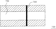
Fig. 7 is the synoptic diagram of the image that sensed of the Image sensor apparatus 240 of Fig. 5.
Fig. 8 is the main process flow diagram of the method that obtains Referent position of one embodiment of the invention.
Fig. 9 is a key diagram of the coordinate values of touch-control system detecting indicant.
Figure 10 is a synoptic diagram of asking for the equation of line of sensing route 902.
Figure 11 is a synoptic diagram of asking for the equation of line of sensing route 904.
100,200,400,500: touch-control system
120,130,220,230,240,250,600: Image sensor apparatus
162,164,282,284,902,904: the sensing route
402,404,406,408: sub-treatment circuit
110,210: panel 112,212: touch-control surface
140,260: treatment circuit 150,270: indicant
502: reflecting body 504: the reflection material
602: infrared illumination device 604: the infrared ray filtering apparatus
606: OPTICAL SENSORS 700: the image sensing window
702: clear zone 704: dark line
906,908: imaginary line S802, S804: step
Embodiment
Reach technological means and the effect that predetermined goal of the invention is taked for further setting forth the present invention, below in conjunction with accompanying drawing and preferred embodiment, touch-control system that foundation the present invention is proposed and its embodiment of method, structure, method (manufacture method, job operation), step, feature and the effect thereof that obtains the position of indicant thereof, describe in detail as after.
Seeing also shown in Figure 2ly, is the synoptic diagram of the touch-control system of one embodiment of the invention.Touch-control system 200 of the present invention also includes Image sensor apparatus 220,230,240 and 250 except including panel 210, and treatment circuit 260.
It is tetragonal touch-control surface 212 that above-mentioned panel 210 has an external form, is rectangle in this example.
Above-mentioned Image sensor apparatus 220,230,240 and 250 is configured in the different corners of touch-control surface 212 respectively, so that the sensing range of these four Image sensor apparatus is contained touch-control surface 212 jointly.In addition, Image sensor apparatus 220,230,240 and 250 all is coupled to above-mentioned treatment circuit 260.
When an indicant 270 touchings (or contiguous) touch-control surface 212, make when Image sensor apparatus 220,230,240 and 250 all senses indicant 270 that these four Image sensor apparatus will send the image of obtaining to treatment circuit 260 respectively.Then, treatment circuit 260 just can be one group mode with per two Image sensor apparatus, a next coordinate values of removing to detect indicant 270 from the obtained image of every group image sensing apparatus, and after detecting six pen stand scale values, calculate the mean value of the coordinate values of indicant 270 according to this six pen stands scale value that detects.And aforesaid numerical value-six, be exactly these four Image sensor apparatus get wherein two the quantity that might make up.Be described in detail as follows.
Suppose that treatment circuit 260 goes out indicant 270 from Image sensor apparatus 220 and 230 obtained image detectings coordinate values is (x1, y1), the coordinate values that goes out indicant 270 from Image sensor apparatus 230 and 250 obtained image detectings is (x2, y2), the coordinate values that goes out indicant 270 from Image sensor apparatus 250 and 240 obtained image detectings is (x3, y3), the coordinate values that goes out indicant 270 from Image sensor apparatus 240 and 220 obtained image detectings is (x4, y4), the coordinate values that goes out indicant 270 from Image sensor apparatus 220 and 250 obtained image detectings is (x5, y5), and the coordinate values that goes out indicant 270 from Image sensor apparatus 230 and 240 obtained image detectings is (x6, y6), treatment circuit 260 will calculate the mean value of the coordinate values of indicant 270 according to this six pen stands scale value that detects so.
Above-mentioned treatment circuit 260 can be the mean value that calculates the coordinate values of indicant 270 with arithmetic mean (arithmetic mean), geometric mean (geometric mean), harmonic average (harmonic mean) or other mode.In the arithmetic mean mode, above-mentioned six pen stand scale values are in the axial mean value of x, and at the axial mean value of y respectively shown in following formula (1) and formula (2):
x
e=(x
1+x
2+x
3+x
4+x
5+x
6)/6……(1)
y
e=(y
1+y
2+y
3+y
4+y
5+y
6)/6……(2)
X wherein
eAnd y
eBeing respectively axial mean value of x and the axial mean value of y, is that the mean value with the coordinate values of indicant 270 is (x
e, y
e).In addition, in the geometric mean mode, above-mentioned six pen stand scale values are in the axial mean value of x, and at the axial mean value of y respectively shown in following formula (3) and formula (4):
X wherein
gAnd y
gBeing respectively axial mean value of x and the axial mean value of y, is that the mean value with the coordinate values of indicant 270 is (x
g, y
g).In addition, in the harmonic average mode, above-mentioned six pen stand scale values are in the axial mean value of x, and at the axial mean value of y respectively shown in following formula (5) and formula (6):
x
h=6/((1/x
1)+(1/x
2)+(1/x
3)
+(1/x
4)+(1/x
5)+(1/x
6))……(5)
y
h=6/((1/y
1)+(1/y
2)+(1/y
3)
+(1/y
4)+(1/y
5)+(1/y
6))……(6)
X wherein
hAnd y
hBeing respectively axial mean value of x and the axial mean value of y, is that the mean value with the coordinate values of indicant 270 is (x
h, y
h).
In view of the above, because treatment circuit 260 can detect the coordinate values of six indicants 270 from the obtained image of six group image sensing apparatus, and calculate the mean value of this six pen stands scale value, so on the location of indicant 270, be difficult for having very big error, make the coordinate location of this touch-control system come accurately than the coordinate location of known techniques.
Although in the above-described embodiments, it is the coordinate values that detects six indicants 270 from the obtained image of six group image sensing apparatus, and then calculate the mean value of this six pen stands scale value, and then reach the effect of dwindling positioning error, yet expansion, as long as can detect the coordinate values of at least two indicants 270, and then calculate the mean value of this strokes coordinate values, just can reach approximate effect.In addition, the quantity of Image sensor apparatus is not to be defined as four yet, as long as have at least three Image sensor apparatus in the touch-control system 200, just can calculate the mean value of the coordinate values of indicant 270.
It is noted that, in framework shown in Figure 2, if treatment circuit 260 detects the mode of the coordinate values of indicant 270 from the obtained image of a group image sensing apparatus, be when trying to achieve, just must note situation shown in Figure 3 in the mode of the intersection point of two sensing routes calculating this group image sensing apparatus.Fig. 3 illustrates cornerwise situation that indicant 270 is positioned at touch-control surface 212.As shown in the figure, in the case, the two can not have intersection point the sensing route 282 of Image sensor apparatus 220 and the sensing route of Image sensor apparatus 250 284, be with treatment circuit 260 when the mean value of the coordinate values of calculating indicant 270, just should not use the mean value that the obtained image of this group image sensing apparatus calculates the coordinate values of indicant 270.
Similarly, if indicant 270 shown in Figure 3 is not only on the diagonal line between Image sensor apparatus 220 and 250, also on the diagonal line between Image sensor apparatus 230 and 240, treatment circuit 260 just should not use the mean value that the obtained image of this two group images sensing apparatus calculates the coordinate values of indicant 270 when the mean value of the coordinate values of calculating indicant 270 so.In like manner,, or have the Image sensor apparatus more than four, also should note aforesaid situation even only have three Image sensor apparatus in the touch-control system 200.
Seeing also shown in Figure 4ly, is the synoptic diagram of the touch-control system of another embodiment of the present invention.The touch-control system 400 of another embodiment of the present invention, it has been in, this touch-control system more than 400 four sub-treatment circuits of the quantity of corresponding Image sensor apparatus with touch-control system 200 shown in Figure 2 different, indicates with 402,404,406 and 408 respectively.Each sub-treatment circuit is coupled in wherein between the Image sensor apparatus and treatment circuit 260, in order to the data of the obtained image of Image sensor apparatus is carried out pre-service, so that treatment circuit 260 detects the coordinate values of indicant 270 according to sub-processing circuit processes data later.
Seeing also shown in Figure 5ly, is the schematic perspective view of the touch-control system of yet another embodiment of the invention.The touch-control system 500 of yet another embodiment of the invention mainly is a framework of continuing to use touch-control system shown in Figure 2 200, and sets up reflecting body 502 again and form.This reflecting body 502 is configured on the touch-control surface 212, and around touch-control surface 212, and the inner edge of this reflecting body 502 has reflection material 504, for example is retro-reflection material (retro-reflective material).
Seeing also shown in Figure 6ly, is a kind of synoptic diagram that is fit to the Image sensor apparatus that uses with reflecting body 502 collocation of Fig. 5.This Image sensor apparatus 600 of the present invention includes infrared ray (infra-red, IR) lighting device 602, the infrared ray filtering apparatus 604 and the OPTICAL SENSORS (photosensor) 606 that can only allow infrared ray pass through.Wherein OPTICAL SENSORS 606 is to see through the image that infrared ray filtering apparatus 604 is obtained touch-control surface, and in order to be coupled to treatment circuit or sub-treatment circuit.In addition, infrared illumination device 602 can utilize infrared light-emitting diode (IR LED) to realize, infrared ray filtering apparatus 604 then can utilize infrared filter (IR-pass filter) to realize.
The Image sensor apparatus 240 of supposing Fig. 5 adopts the framework of Image sensor apparatus 600 shown in Figure 6, and its infrared illumination device operate as normal, and the image that sensed of this Image sensor apparatus 240 just as shown in Figure 7 so.The synoptic diagram of the image that Fig. 7 is sensed for the Image sensor apparatus 240 of Fig. 5.In this figure, sign 700 is expressed as the image sensing window (imagesensing window) of Image sensor apparatus 240.And indicate 702 promptly is to form the higher clear zone (bright zone) of brightness on image by reflection material 504 reflection rays of reflecting body 502, and this clear zone 702 is exactly main sensing area.As for indicating 704, then be the dark line that indicant 270 is caused.By as can be known above-mentioned, reflection material 504 is when Image sensor apparatus 240 obtains the image of touch-control surface 212, is used for main background as indicant 270, is beneficial to highlight the position of indicant 270.
By the teaching of the various embodiments described above, can also summarize a kind of method that obtains the position of indicant, as shown in Figure 8.Fig. 8 is the main process flow diagram of the method that obtains Referent position of one embodiment of the invention.The method that obtains Referent position of the present invention is applicable to a kind of touch-control system, and described touch-control system has and is shaped as a tetragonal touch-control surface and at least three Image sensor apparatus, these Image sensor apparatus are configured in the different corners of touch-control surface respectively, and the sensing range of these Image sensor apparatus is contained touch-control surface jointly.In the method, when the contiguous touch-control surface of an indicant,, come a coordinate values (shown in step S802) of removing to detect above-mentioned indicant from the obtained image of every group image sensing apparatus just be one group mode with per two Image sensor apparatus.Then, after detecting at least two pen stand scale values, calculate the mean value (shown in step S804) of the coordinate values of indicant according to the coordinate values that detects.
Certainly, as described in previous each embodiment, calculate the mode of the mean value of above-mentioned coordinate values, comprise it being that mode with arithmetic mean, geometric mean or harmonic average is calculated.In addition, calculate the opportunity of the mean value of above-mentioned coordinate values, comprise it being after detecting the N pen stand scale value of indicant, calculate the mean value of the coordinate values of indicant according to this N pen stand scale value, wherein N for get by above-mentioned all Image sensor apparatus wherein two the quantity that might make up.
What deserves to be mentioned is, from the coordinate values that two obtained images of Image sensor apparatus remove to detect indicant, be to adopt multiple diverse ways, for example can adopt the method that is proposed in the 4th, 782, No. 328 patents of the U.S..Yet, below will reintroduce another kind of method, to provide system designer many a kind of selections.See also shown in Figure 9ly, it is a key diagram of the coordinate values of touch-control system detecting indicant.In Fig. 9, indicate 220 and 230 and be all Image sensor apparatus, indicating 212 then is the touch-control surface that is shaped as rectangle.As for indicating 270, it is expressed as indicant. Image sensor apparatus 220 and 230 can be respectively along sensing route 902 and 904 and sense indicant 270.Be with, as long as obtain the equation of line of these two sensing routes, just can ask for the intersection point of these two sensing routes, with coordinate values as indicant 270.Further specify with Figure 10 and Figure 11 again.
Figure 10 is a key diagram of asking for the equation of line of sensing route 902.Please refer to Figure 10, ask for the equation of line of sensing route 902, will obtain the coordinate values of an A and some A ' earlier.Because the size of touch-control surface 212 is fixed, the coordinate values of therefore putting A, B, C and D is known, so only there is the Building X of an A ' to be designated as the unknown.Be with, can provide an imaginary line 906 again between the D at a B and point, make the intersection point of sensing route 902 and imaginary line 906 be a some Z.Thus, line segment
And
 The triangle of being formed, and line segment
 And
And
 The triangle of being formed, these two triangles can be similar triangles (similar triangles) and present a proportionate relationship.Next, because the resolution of Image sensor apparatus 220 also is known, so can be by calculating in the imaginary line 906 line segment
Picture element quantity and line segment
The triangle of being formed, these two triangles can be similar triangles (similar triangles) and present a proportionate relationship.Next, because the resolution of Image sensor apparatus 220 also is known, so can be by calculating in the imaginary line 906 line segment
Picture element quantity and line segment
 Picture element quantity, and learn the ratio of these two line segments.Because line segment
 And line segment
 Also be to present same proportionate relationship, and line segment
 Length be known, so can obtain line segment
 Length and obtain the Building X mark of an A '.So, next just can ask for the equation of line of sensing route 902 according to the coordinate values of an A and some A '.
In like manner, the equation of line of sensing route 904 also can adopt similar mode to ask for, as shown in figure 11.Figure 11 is a key diagram of asking for the equation of line of sensing route 904.Please refer to Figure 11, wherein indicate 908 and also be imaginary line, and some Z ' is the intersection point of sensing route 904 and imaginary line 908.Be with, line segment
 And
The triangle of being formed, and line segment
And
And
The triangle of being formed, and line segment
And
 The triangle of being formed, these two triangles also can be similar triangles and present a proportionate relationship.Next, just can obtain
 And
And
 The ratio of these two line segments, and calculate line segment according to this
 Length and obtain the Building X mark of a B '.So, next just can ask for the equation of line of
 sensing route 904 according to the coordinate values of a B and some B '.After the equation of line that obtains sensing route 902 and 904, just can further calculate the intersection point of sensing route 902 and 904.
In sum, the present invention ties up at least three Image sensor apparatus of configuration in the touch-control system, and with per two Image sensor apparatus one group mode, a next coordinate values of removing to detect indicant from the obtained image of every group image sensing apparatus, and after detecting at least two pen stand scale values, calculate the mean value of the coordinate values of indicant according to the coordinate values that detects.Be with, for existing known technology, touch-control system of the present invention can carry out the coordinate location more exactly.
The above, it only is preferred embodiment of the present invention, be not that the present invention is done any pro forma restriction, though the present invention discloses as above with preferred embodiment, yet be not in order to limit the present invention, any those skilled in the art, in not breaking away from the technical solution of the present invention scope, when the method that can utilize above-mentioned announcement and technology contents are made a little change or be modified to the equivalent embodiment of equivalent variations, in every case be the content that does not break away from technical solution of the present invention, according to technical spirit of the present invention to any simple modification that above embodiment did, equivalent variations and modification all still belong in the scope of technical solution of the present invention.
Claims (12)
1. touch-control system is characterized in that comprising:
One touch-control surface is shaped as a quadrilateral;
At least three Image sensor apparatus be configured in the different corners of this touch-control surface respectively, and the sensing range of described Image sensor apparatus are contained this touch-control surface jointly; And
One treatment circuit, couple above-mentioned each Image sensor apparatus, when this touch-control surface of indicant vicinity, this treatment circuit is one group mode with per two Image sensor apparatus, one coordinate values of removing to detect this indicant from the obtained image of every group image sensing apparatus, and after detecting at least two pen stand scale values, calculate the mean value of the coordinate values of this indicant according to the coordinate values that detects.
2. touch-control system according to claim 1 is characterized in that it is the mean value that calculates the coordinate values of this indicant in the mode of arithmetic mean, geometric mean or harmonic average that wherein said treatment circuit comprises.
3. touch-control system according to claim 1, it is characterized in that it is after detecting the N pen stand scale value of this indicant that wherein said treatment circuit comprises, calculate the mean value of the coordinate values of this indicant according to this N pen stand scale value, wherein N for get by described Image sensor apparatus wherein two the quantity that might make up.
4. touch-control system according to claim 1, the sub-treatment circuit that it is characterized in that the quantity that it also comprises corresponding described Image sensor apparatus, wherein, each sub-treatment circuit is coupled to wherein between the Image sensor apparatus and this treatment circuit, in order to the data of the obtained image of Image sensor apparatus is carried out pre-service, so that this treatment circuit detects the coordinate values of this indicant according to sub-processing circuit processes data later.
5. touch-control system according to claim 1 is characterized in that it also has a reflecting body, and this reflecting body is configured on this touch-control surface, and around this touch-control surface, the inner edge of this reflecting body has the reflection material.
6. touch-control system according to claim 1 is characterized in that wherein said each Image sensor apparatus has an infrared illumination device.
7. touch-control system according to claim 6 is characterized in that wherein said infrared illumination device comprises an infrared light-emitting diode.
8. touch-control system according to claim 6, it is characterized in that wherein said each Image sensor apparatus also has an infrared ray filtering apparatus that can only allow infrared ray pass through, and each Image sensor apparatus is to see through the image that its infrared ray filtering apparatus is obtained this touch-control surface.
9. touch-control system according to claim 1 is characterized in that the rectangle that is shaped as of wherein said touch-control surface.
10. method that obtains the position of indicant, be applicable to a touch-control system, it is characterized in that wherein that this touch-control system has is shaped as a tetragonal touch-control surface and at least three Image sensor apparatus, described Image sensor apparatus is configured in the different corners of this touch-control surface respectively, and the sensing range of described Image sensor apparatus is contained this touch-control surface jointly, and this method may further comprise the steps:
When contiguous this touch-control surface of an indicant, be one group mode with per two Image sensor apparatus, a coordinate values of removing to detect this indicant from the obtained image of every group image sensing apparatus; And
After detecting at least two pen stand scale values, calculate the mean value of the coordinate values of this indicant according to the coordinate values that detects.
11. method according to claim 10 is characterized in that the mean value of the coordinate values of wherein said this indicant of calculating comprises it being the mean value that calculates the coordinate values of this indicant in the mode of arithmetic mean, geometric mean or harmonic average.
12. method according to claim 10, it is characterized in that comprising being after detecting the N pen stand scale value of this indicant, calculate the mean value of the coordinate values of this indicant according to this N pen stand scale value, wherein N for get by described Image sensor apparatus wherein two the quantity that might make up.
Priority Applications (1)
| Application Number | Priority Date | Filing Date | Title |
|---|---|---|---|
| CN200810180718A CN101751165A (en) | 2008-11-28 | 2008-11-28 | Touch-control system and method thereof for obtaining location of referent |
Applications Claiming Priority (1)
| Application Number | Priority Date | Filing Date | Title |
|---|---|---|---|
| CN200810180718A CN101751165A (en) | 2008-11-28 | 2008-11-28 | Touch-control system and method thereof for obtaining location of referent |
Publications (1)
| Publication Number | Publication Date |
|---|---|
| CN101751165A true CN101751165A (en) | 2010-06-23 |
Family
ID=42478207
Family Applications (1)
| Application Number | Title | Priority Date | Filing Date |
|---|---|---|---|
| CN200810180718A Pending CN101751165A (en) | 2008-11-28 | 2008-11-28 | Touch-control system and method thereof for obtaining location of referent |
Country Status (1)
| Country | Link |
|---|---|
| CN (1) | CN101751165A (en) |
Cited By (5)
| Publication number | Priority date | Publication date | Assignee | Title |
|---|---|---|---|---|
| CN102298458A (en) * | 2010-06-24 | 2011-12-28 | 原相科技股份有限公司 | Touch system and positioning method thereof |
| CN102402342A (en) * | 2010-09-08 | 2012-04-04 | 广达电脑股份有限公司 | Optical touch system and method |
| CN102055919B (en) * | 2009-11-04 | 2012-11-07 | 原相科技股份有限公司 | Complementary metal oxide semiconductor image sensor and method of operation thereof |
| CN104679352A (en) * | 2013-11-29 | 2015-06-03 | 纬创资通股份有限公司 | Optical touch device and touch point detection method |
| CN104679353A (en) * | 2013-11-29 | 2015-06-03 | 纬创资通股份有限公司 | Optical touch device and calculation method of touch point coordinates |
-
2008
- 2008-11-28 CN CN200810180718A patent/CN101751165A/en active Pending
Cited By (9)
| Publication number | Priority date | Publication date | Assignee | Title |
|---|---|---|---|---|
| CN102055919B (en) * | 2009-11-04 | 2012-11-07 | 原相科技股份有限公司 | Complementary metal oxide semiconductor image sensor and method of operation thereof |
| CN102298458A (en) * | 2010-06-24 | 2011-12-28 | 原相科技股份有限公司 | Touch system and positioning method thereof |
| CN102298458B (en) * | 2010-06-24 | 2013-11-13 | 原相科技股份有限公司 | Positioning method of touch system |
| CN102402342A (en) * | 2010-09-08 | 2012-04-04 | 广达电脑股份有限公司 | Optical touch system and method |
| CN102402342B (en) * | 2010-09-08 | 2015-04-22 | 广达电脑股份有限公司 | Optical touch system and method |
| CN104679352A (en) * | 2013-11-29 | 2015-06-03 | 纬创资通股份有限公司 | Optical touch device and touch point detection method |
| CN104679353A (en) * | 2013-11-29 | 2015-06-03 | 纬创资通股份有限公司 | Optical touch device and calculation method of touch point coordinates |
| CN104679353B (en) * | 2013-11-29 | 2017-08-25 | 纬创资通股份有限公司 | Optical touch device and calculation method of touch point coordinates |
| CN104679352B (en) * | 2013-11-29 | 2017-12-08 | 纬创资通股份有限公司 | Optical touch device and touch point detection method |
Similar Documents
| Publication | Publication Date | Title |
|---|---|---|
| JP6027328B2 (en) | Display device and object display method thereof | |
| TWI433003B (en) | Touch-control system and touch-sensing method thereof | |
| CN103616972B (en) | Touch screen control method and terminal device | |
| US20150301642A1 (en) | Projected Capacitive Touch with Force Detection | |
| JP2005258810A5 (en) | ||
| KR20110088872A (en) | Image output position control device of flexible display | |
| CN101751165A (en) | Touch-control system and method thereof for obtaining location of referent | |
| KR20140099128A (en) | Stretchable display and method for controlling the same | |
| TWI377494B (en) | Variable-size sensing system and method for redefining size of sensing area thereof | |
| TW201218042A (en) | Optical screen touch system and method thereof | |
| WO2016032107A1 (en) | Digitizer having improvement in positioning accuracy | |
| US20130285957A1 (en) | Display device and method using a plurality of display panels | |
| US20150363043A1 (en) | Touch panel device and touch panel device control method | |
| TWI553532B (en) | Optical touch device and sensing method thereof | |
| CN201611477U (en) | Optical touch screen | |
| WO2012153536A1 (en) | Coordinates input device and coordinates input method | |
| TWI590131B (en) | Optical touch device and method for detecting touch point | |
| JP2010267245A (en) | Control method for sensor system | |
| CN101799726B (en) | Variable-size sensing system and method for redefining size of sensing region thereof | |
| WO2018045209A1 (en) | Full-bridge strain-gauge array of finger thermal compensation | |
| CN103543883B (en) | Optical touch method and system thereof | |
| US11144162B1 (en) | Device and method for sensor electrode testing | |
| CN101840281B (en) | Sensing system and method thereof for obtaining position of pointer | |
| CN101976151B (en) | Touch-free control device and touch-free control method thereof | |
| CN201773382U (en) | Touch screen with camera |
Legal Events
| Date | Code | Title | Description |
|---|---|---|---|
| C06 | Publication | ||
| PB01 | Publication | ||
| C10 | Entry into substantive examination | ||
| SE01 | Entry into force of request for substantive examination | ||
| C02 | Deemed withdrawal of patent application after publication (patent law 2001) | ||
| WD01 | Invention patent application deemed withdrawn after publication |
Application publication date: 20100623 |