CN101742819B - Circuit board compobination - Google Patents
Circuit board compobination Download PDFInfo
- Publication number
- CN101742819B CN101742819B CN200810305684.0A CN200810305684A CN101742819B CN 101742819 B CN101742819 B CN 101742819B CN 200810305684 A CN200810305684 A CN 200810305684A CN 101742819 B CN101742819 B CN 101742819B
- Authority
- CN
- China
- Prior art keywords
- circuit board
- base
- chip
- heat sink
- chip base
- Prior art date
- Legal status (The legal status is an assumption and is not a legal conclusion. Google has not performed a legal analysis and makes no representation as to the accuracy of the status listed.)
- Expired - Fee Related
Links
Images


Classifications
-
- H—ELECTRICITY
- H10—SEMICONDUCTOR DEVICES; ELECTRIC SOLID-STATE DEVICES NOT OTHERWISE PROVIDED FOR
- H10W—GENERIC PACKAGES, INTERCONNECTIONS, CONNECTORS OR OTHER CONSTRUCTIONAL DETAILS OF DEVICES COVERED BY CLASS H10
- H10W40/00—Arrangements for thermal protection or thermal control
- H10W40/60—Securing means for detachable heating or cooling arrangements, e.g. clamps
- H10W40/641—Snap-on arrangements, e.g. clips
-
- H—ELECTRICITY
- H10—SEMICONDUCTOR DEVICES; ELECTRIC SOLID-STATE DEVICES NOT OTHERWISE PROVIDED FOR
- H10W—GENERIC PACKAGES, INTERCONNECTIONS, CONNECTORS OR OTHER CONSTRUCTIONAL DETAILS OF DEVICES COVERED BY CLASS H10
- H10W40/00—Arrangements for thermal protection or thermal control
- H10W40/60—Securing means for detachable heating or cooling arrangements, e.g. clamps
- H10W40/611—Bolts or screws
Landscapes
- Cooling Or The Like Of Electrical Apparatus (AREA)
- Cooling Or The Like Of Semiconductors Or Solid State Devices (AREA)
Abstract
一种电路板组合,其包括一电路板、一装配于该电路板上的芯片底座及一安装在该芯片底座上的散热器,散热器具有一底座及若干自底座向上延伸的散热鳍片,芯片底座的四角上分别设有向下延伸的支脚,芯片底座的支脚支撑在所述电路板上。电路板组合能有效地防止压损芯片底座焊脚。
A circuit board combination, which includes a circuit board, a chip base assembled on the circuit board and a radiator installed on the chip base, the radiator has a base and a plurality of cooling fins extending upward from the base, the chip Four corners of the base are respectively provided with supporting feet extending downward, and the supporting feet of the chip base are supported on the circuit board. The circuit board combination can effectively prevent the pressure loss of the chip base solder feet.
Description
技术领域 technical field
本发明涉及一种电路板组合,特别是关于一种设有散热器的电路板组合。The invention relates to a circuit board combination, in particular to a circuit board combination provided with a radiator.
背景技术 Background technique
随着电脑技术的不断发展,电脑功能越来越多,相应地电脑元件也越来越多,为了提高电脑工作的稳定性,电脑内部使用了许多散热装置,当前电脑内使用的散热器主要用于芯片的散热,如何将散热器固定在电路板上,则显得非常重要。With the continuous development of computer technology, there are more and more computer functions, and accordingly there are more and more computer components. In order to improve the stability of computer work, many cooling devices are used inside the computer. The radiators used in the current computer are mainly used For the heat dissipation of the chip, how to fix the heat sink on the circuit board is very important.
业界也推出一种晶片散热器固定夹,其为一夹具单体,用于方便地将一铝挤型散热器固定于晶片表面,其由一中间框架和设于框架两对角端的弹性扣件所组成,弹性扣件设成连续弯曲段,并于末端形成一弯钩状,用以插置入印刷电路板上对应位置的扣合孔中,此弹性扣件与中间框架是一体成型的,组装时,框架恰可嵌置于铝挤型散热器表面压合槽中。但目前出于环保考虑,通常采用无铅焊料焊接芯片底座,芯片底座的焊脚较脆,装配散热器过程中,固定夹一端扣入电路板的扣合孔中,电路板有一定的形变,这样有可能造成电路板上芯片底座的焊脚松动,且固定夹有一定的弹力施加在散热器上,而散热器本身有一定的重量,这样芯片底座上安装的芯片所受外来压力较大,容易造成芯片底座的焊脚损坏。The industry also introduces a chip heat sink fixing clip, which is a single fixture used to easily fix an aluminum extruded heat sink on the surface of the chip. The elastic fastener is formed into a continuous curved section, and a hook shape is formed at the end, which is used to be inserted into the fastening hole at the corresponding position on the printed circuit board. The elastic fastener and the middle frame are integrally formed. When assembled, the frame can just be embedded in the pressing groove on the surface of the extruded aluminum radiator. However, due to environmental protection considerations, lead-free solder is usually used to weld the chip base. The solder feet of the chip base are relatively brittle. During the process of assembling the heat sink, one end of the fixing clip is buckled into the fastening hole of the circuit board, and the circuit board is deformed to a certain extent. This may cause the solder pins of the chip base on the circuit board to loosen, and the fixing clip has a certain elastic force applied to the heat sink, and the heat sink itself has a certain weight, so the external pressure on the chip installed on the chip base is relatively large. It is easy to cause damage to the solder feet of the chip base.
发明内容 Contents of the invention
鉴于以上内容,有必要提供一种有效地防止散热器压损芯片底座焊脚的电路板组合。In view of the above, it is necessary to provide a circuit board combination that can effectively prevent the heat sink from damaging the solder pins of the chip base.
一种电路板组合,其包括一电路板、一装配于该电路板上的芯片底座及一安装在该芯片底座上的散热器,所述散热器具有一底座及若干自该底座向上延伸的散热鳍片,所述芯片底座的四角上分别设有向下延伸的支脚,所述芯片底座的支脚支撑在所述电路板上。A circuit board combination, which includes a circuit board, a chip base assembled on the circuit board, and a heat sink installed on the chip base, the heat sink has a base and a plurality of heat dissipation fins extending upward from the base The four corners of the chip base are respectively provided with downwardly extending legs, and the legs of the chip base are supported on the circuit board.
相较于现有技术,所述芯片底座上的支脚支撑芯片底座,避免过多的压力施加在电路板和芯片底座之间的焊锡层上,所述电路板组合能有效地防止压损焊脚。Compared with the prior art, the legs on the chip base support the chip base, avoiding excessive pressure from being applied to the solder layer between the circuit board and the chip base, and the circuit board combination can effectively prevent pressure damage to the solder pins .
附图说明 Description of drawings
下面参照附图结合实施方式对本发明作进一步的描述。The present invention will be further described below with reference to the accompanying drawings and embodiments.
图1是本发明电路板组合较佳实施例的立体分解图。FIG. 1 is an exploded perspective view of a preferred embodiment of the circuit board assembly of the present invention.
图2是图1中的电路板组合组装后的剖面图。FIG. 2 is a cross-sectional view of the assembled circuit board in FIG. 1 .
图3是本发明电路板组合另一较佳实施例的立体分解图。FIG. 3 is an exploded perspective view of another preferred embodiment of the circuit board assembly of the present invention.
图4是图3中的电路板组合组装后的剖面图。FIG. 4 is a cross-sectional view of the assembled circuit board in FIG. 3 .
具体实施方式 Detailed ways
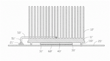
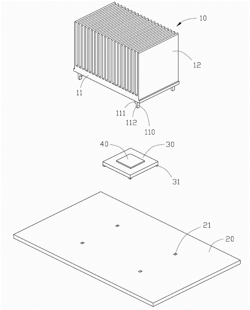
请参阅图1和图2,一电路板组合包括一电路板20、一安装在所述电路板20上的芯片底座30、一装配在所述芯片底座30上的芯片40及一安装在所述芯片40上的散热器10。Referring to Fig. 1 and Fig. 2, a circuit board combination comprises a
所述散热器10设有一底座11及若干自所述底座11向上延伸形成的散热鳍片12。所述底座11在四角分别设有一向下延伸的支脚110,所述支脚110大体呈一阶梯形,每一支脚110设有一横截面积较大的限位部111及一自所述限位部111延伸形成的横截面积较小的插入部112。所述芯片底座30安装于所述电路板20上,其下表面在四角分别设有一向下延伸的支脚31。所述芯片底座30和电路板20之间涂有一焊锡层50。所述电路板20上设有与所述插入部112相应的开孔21,所述开孔21的横截面积比所述限位部111的横截面积小,以限制所述限位部111通过所述开孔21,所述限位部111的竖直高度略大于所述芯片底座30的竖直高度,所述芯片40装配于芯片底座30上且略高出于芯片底座30的上表面,所述芯片40的上表面涂有一层导热介质并与底座11的下表面相接触。The
安装所述散热器10时,所述散热器10的插入部112穿过所述电路板20的开孔21,所述限位部11 1无法通过开孔21而与所述电路板20的上表面相抵,此时所述散热器10的底座11压在所述芯片底座30上的芯片40上,由于支脚110的限位部111支撑在所述电路板20上,所述支脚110承载了所述散热器10大部分重力,从而芯片底座30和芯片40承担散热器10施加的压力得以减少。所述散热器10的插入部112通过焊接、粘接或螺丝锁固等方式将所述散热器10固定在所述电路板20上。另外,由于支脚31将所述芯片底座30支撑在电路板20上,所述支脚31承载了所述芯片底座30和芯片40的大部分重力,从而进一步降低了芯片底座30上承受的压力,避免了电路板20和芯片底座30之间的焊锡层50承受过大的压力而导致的焊脚损坏。When installing the
请参阅图3和图4,在本发明电路板组合另一实施方式中,一电路板组合包括一电路板20’、一安装在所述电路板20’上的芯片底座30’、一装配在所述芯片底座30’上的芯片40’、一安装在所述芯片40’上的散热器10’及一常见的散热器扣具,在本实施例中,所述扣具为一弹性钢丝50’。Please refer to Fig. 3 and Fig. 4, in another embodiment of the circuit board assembly of the present invention, a circuit board assembly includes a circuit board 20', a chip base 30' mounted on the circuit board 20', a The chip 40' on the chip base 30', a radiator 10' installed on the chip 40' and a common radiator fastener, in this embodiment, the fastener is an elastic steel wire 50 '.
所述散热器10’设有一底座11’及若干自所述底座11’向上延伸形成的散热鳍片12’。所述底座11’在四角分别设有一向下延伸的支脚110’,每一支脚110’的竖直高度略高于所述芯片底座30’的竖直高度,所述芯片40’装配于芯片底座30’上且略高出于芯片底座30’的上表面,所述芯片40’的上表面涂有一层导热介质并与底座11’的下表面相接触。所述芯片底座30’安装于所述电路板20’上,其下表面在四角分别设有一向下延伸的支脚31’。所述芯片底座30’和电路板20’之间涂有一焊锡层60’。所述钢丝50’两端分别设有一卡钩51’,所述电路板20’上设有供卡钩51’卡合的卡合部21’。The heat sink 10' is provided with a base 11' and a plurality of cooling fins 12' extending upward from the base 11'. The base 11' is respectively provided with a downward extending leg 110' at the four corners, the vertical height of each leg 110' is slightly higher than the vertical height of the chip base 30', and the chip 40' is assembled on the chip base 30' and slightly higher than the upper surface of the chip base 30', the upper surface of the chip 40' is coated with a layer of heat-conducting medium and is in contact with the lower surface of the base 11'. The chip base 30' is mounted on the circuit board 20', and its lower surface is provided with a downward extending leg 31' at four corners. A solder layer 60' is coated between the chip base 30' and the circuit board 20'. Two ends of the steel wire 50' are respectively provided with a hook 51', and the circuit board 20' is provided with an engaging portion 21' for engaging the hook 51'.
安装所述散热器10’时,首先将所述散热器10’放置在所述芯片底座30’上,此时所述散热器10’的底座11’挤压所述芯片30’上的芯片40’,由于支脚110’支撑在所述电路板20’上,所述支脚110’承载了所述散热器10’大部分重力,从而芯片底座30’和芯片40’承担散热器10’施加的压力得以减少。然后将所述钢丝40’穿过散热器10’并将其两端的卡钩41’分别与所述电路板20’的卡合部21’卡合,从而将所述散热器10’固定在所述电路板20’上。另外,由于支脚31’将所述芯片底座30’支撑在电路板20’上,所述支脚31’承载了所述芯片底座30’和芯片40’的大部分重力,从而进一步降低了芯片底座30’上承受的压力,避免了电路板20’和芯片底座30’之间的焊锡层60’承受过大的压力而导致的焊脚损坏。When installing the heat sink 10', first place the heat sink 10' on the chip base 30', at this time the base 11' of the heat sink 10' presses the
在上述两个实施方式中,所述支脚31,31’,110,110’可以设有多个,其可为不同形状;所述电路板20,20’可在与所述支脚31,31’,110’对应的位置上设有凹槽,以让支脚31,31’,110’更好的定位;所述支脚110,110’可与所述散热器10,10’非一体形成,作为单个的元件固定于散热器10,10’底座,构成了底座向下延伸的支脚。In the two above-mentioned embodiments, the
Claims (9)
Priority Applications (2)
| Application Number | Priority Date | Filing Date | Title |
|---|---|---|---|
| CN200810305684.0A CN101742819B (en) | 2008-11-21 | 2008-11-21 | Circuit board compobination |
| US12/464,519 US20100128442A1 (en) | 2008-11-21 | 2009-05-12 | Heat sink assembly |
Applications Claiming Priority (1)
| Application Number | Priority Date | Filing Date | Title |
|---|---|---|---|
| CN200810305684.0A CN101742819B (en) | 2008-11-21 | 2008-11-21 | Circuit board compobination |
Publications (2)
| Publication Number | Publication Date |
|---|---|
| CN101742819A CN101742819A (en) | 2010-06-16 |
| CN101742819B true CN101742819B (en) | 2013-03-20 |
Family
ID=42196057
Family Applications (1)
| Application Number | Title | Priority Date | Filing Date |
|---|---|---|---|
| CN200810305684.0A Expired - Fee Related CN101742819B (en) | 2008-11-21 | 2008-11-21 | Circuit board compobination |
Country Status (2)
| Country | Link |
|---|---|
| US (1) | US20100128442A1 (en) |
| CN (1) | CN101742819B (en) |
Families Citing this family (3)
| Publication number | Priority date | Publication date | Assignee | Title |
|---|---|---|---|---|
| US10420203B2 (en) | 2013-07-01 | 2019-09-17 | Hamilton Sundstrand Corporation | Heat pipe embedded heat sink with integrated posts |
| US11699884B2 (en) | 2020-07-27 | 2023-07-11 | International Business Machines Corporation | Electromagnetic shielding of heatsinks with spring press-fit pins |
| CN111933593A (en) * | 2020-10-12 | 2020-11-13 | 山东天瑞重工有限公司 | A magnetic bearing power amplifier module |
Citations (2)
| Publication number | Priority date | Publication date | Assignee | Title |
|---|---|---|---|---|
| CN2565150Y (en) * | 2001-10-03 | 2003-08-06 | 朱和纲 | Integrated circuit package assembly with holding mechanism |
| CN200969704Y (en) * | 2006-09-05 | 2007-10-31 | 鸿富锦精密工业(深圳)有限公司 | Circuit board combination |
Family Cites Families (37)
| Publication number | Priority date | Publication date | Assignee | Title |
|---|---|---|---|---|
| US4593342A (en) * | 1984-11-15 | 1986-06-03 | General Electric Company | Heat sink assembly for protecting pins of electronic devices |
| US4745456A (en) * | 1986-09-11 | 1988-05-17 | Thermalloy Incorporated | Heat sink clip assembly |
| US4716494A (en) * | 1986-11-07 | 1987-12-29 | Amp Incorporated | Retention system for removable heat sink |
| US5485351A (en) * | 1989-06-09 | 1996-01-16 | Labinal Components And Systems, Inc. | Socket assembly for integrated circuit chip package |
| US5331507A (en) * | 1991-05-15 | 1994-07-19 | Dell Usa L.P. | Clip for mounting a heat sink on an electronic device package |
| JP2902531B2 (en) * | 1992-12-25 | 1999-06-07 | 富士通株式会社 | Heat dissipation device for semiconductor device |
| US5436798A (en) * | 1994-01-21 | 1995-07-25 | Wakefield Engineering, Inc. | Spring clip and heat sink assembly for electronic components |
| US5586005A (en) * | 1995-03-16 | 1996-12-17 | International Business Machines Corporation | Removable heat sink assembly for a chip package |
| US5566052A (en) * | 1995-06-08 | 1996-10-15 | Northern Telecom Limited | Electronic devices with electromagnetic radiation interference shields and heat sinks |
| US5847928A (en) * | 1996-07-09 | 1998-12-08 | Thermalloy, Inc. | Strap spring for attaching heat sinks to circuit boards |
| US5945736A (en) * | 1998-09-28 | 1999-08-31 | Chip Coolers, Inc. | Heat sink assembly with snap-in cover plate having multiple pressure capability |
| US6021045A (en) * | 1998-10-26 | 2000-02-01 | Chip Coolers, Inc. | Heat sink assembly with threaded collar and multiple pressure capability |
| US6075699A (en) * | 1999-01-29 | 2000-06-13 | Chip Coolers, Inc. | Heat sink assembly with snap-in legs |
| US6201697B1 (en) * | 1999-02-16 | 2001-03-13 | Chip Coolers, Inc. | Heat sink assembly with cam lock |
| TW433624U (en) * | 1999-04-06 | 2001-05-01 | Hon Hai Prec Ind Co Ltd | Electrical connector |
| US6219241B1 (en) * | 1999-06-11 | 2001-04-17 | Intel Coroporation | Advanced zero-insertion force (ZIF) socket with heat sink alignment and retention mechanisms |
| US6205026B1 (en) * | 2000-01-31 | 2001-03-20 | Intel Corporation | Heat sink retention components and system |
| US6293331B1 (en) * | 2000-08-11 | 2001-09-25 | Tyco Electronics Logistics Ag | Vibration and shock resistant heat sink assembly |
| US6396697B1 (en) * | 2000-12-07 | 2002-05-28 | Foxconn Precision Components Co., Ltd. | Heat dissipation assembly |
| US6542367B2 (en) * | 2001-05-31 | 2003-04-01 | Intel Corporation | Securing heat sinks |
| US6392889B1 (en) * | 2001-08-21 | 2002-05-21 | Foxconn Precision Components Co., Ltd. | Fastener for heat sink |
| US6400577B1 (en) * | 2001-08-30 | 2002-06-04 | Tyco Electronics Corporation | Integrated circuit socket assembly having integral shielding members |
| US6590771B2 (en) * | 2001-12-03 | 2003-07-08 | Intel Corporation | Heat sink assembly and method |
| US20030106670A1 (en) * | 2001-12-10 | 2003-06-12 | Lee Hsieh Kun | Clip for heat sink |
| US6545879B1 (en) * | 2002-01-10 | 2003-04-08 | Tyco Electronics Corporation | Method and apparatus for mounting a lidless semiconductor device |
| US6936919B2 (en) * | 2002-08-21 | 2005-08-30 | Texas Instruments Incorporated | Heatsink-substrate-spacer structure for an integrated-circuit package |
| TW539391U (en) * | 2002-09-17 | 2003-06-21 | Hon Hai Prec Ind Co Ltd | Fixing apparatus |
| JP4281864B2 (en) * | 2003-04-30 | 2009-06-17 | タイコエレクトロニクスアンプ株式会社 | IC socket assembly |
| TWM246674U (en) * | 2003-11-21 | 2004-10-11 | Hon Hai Prec Ind Co Ltd | Clip for heat sink |
| US7209354B2 (en) * | 2003-12-02 | 2007-04-24 | Silicon Intergrated Systems Corp. | Ball grid array package with heat sink device |
| CN2694358Y (en) * | 2004-03-30 | 2005-04-20 | 鸿富锦精密工业(深圳)有限公司 | Fastener of heat sink |
| US7690925B2 (en) * | 2005-02-24 | 2010-04-06 | Advanced Interconnections Corp. | Terminal assembly with pin-retaining socket |
| CN100469225C (en) * | 2005-10-07 | 2009-03-11 | 富准精密工业(深圳)有限公司 | Radiator fastener and heat dissipation device assembly using the fastener |
| US7463496B2 (en) * | 2006-03-09 | 2008-12-09 | Laird Technologies, Inc. | Low-profile board level EMI shielding and thermal management apparatus and spring clips for use therewith |
| US20080089031A1 (en) * | 2006-10-17 | 2008-04-17 | Hon Hai Precision Industry Co., Ltd. | Heat sink assembly |
| US20090051004A1 (en) * | 2007-08-24 | 2009-02-26 | Roth Weston C | Surface Mount Components Joined Between a Package Substrate and a Printed Circuit Board |
| US7785114B2 (en) * | 2008-06-30 | 2010-08-31 | Intel Corporation | Modification of connections between a die package and a system board |
-
2008
- 2008-11-21 CN CN200810305684.0A patent/CN101742819B/en not_active Expired - Fee Related
-
2009
- 2009-05-12 US US12/464,519 patent/US20100128442A1/en not_active Abandoned
Patent Citations (2)
| Publication number | Priority date | Publication date | Assignee | Title |
|---|---|---|---|---|
| CN2565150Y (en) * | 2001-10-03 | 2003-08-06 | 朱和纲 | Integrated circuit package assembly with holding mechanism |
| CN200969704Y (en) * | 2006-09-05 | 2007-10-31 | 鸿富锦精密工业(深圳)有限公司 | Circuit board combination |
Also Published As
| Publication number | Publication date |
|---|---|
| US20100128442A1 (en) | 2010-05-27 |
| CN101742819A (en) | 2010-06-16 |
Similar Documents
| Publication | Publication Date | Title |
|---|---|---|
| CN101668406B (en) | Electronic device and support element thereof | |
| US7639504B2 (en) | Mounting device for mounting heat sink onto electronic component | |
| CN105684564B (en) | Heat sink assembly with frame clips for fully assembled attachment to heat generating components | |
| CN101605446B (en) | Radiating device | |
| KR20100010559U (en) | Heatsink | |
| CN101636064B (en) | Radiator fastener and heat sink | |
| US20090195987A1 (en) | Positioning Device For Heatsink | |
| CN101616563A (en) | Heat sink combination | |
| US7768786B2 (en) | Heatsink assembly | |
| CN101742819B (en) | Circuit board compobination | |
| CN100592855C (en) | Radiator fixing device | |
| CN101466242B (en) | Radiating device | |
| CN200969704Y (en) | Circuit board combination | |
| CN101304644B (en) | Radiator fastening device | |
| CN100584161C (en) | Radiator fastening device | |
| CN100562237C (en) | heat sink | |
| TWI446148B (en) | Printed circuit board assembly | |
| CN204145963U (en) | Retainer and there is the electronic device assembly of this retainer | |
| CN101336062A (en) | Heat sink combination | |
| CN101902892A (en) | Radiator Fixture | |
| CN101203119B (en) | heat sink | |
| CN101868134A (en) | Radiator and method of manufacturing the same | |
| CN201066982Y (en) | Heat dissipation module with low wind resistance and high heat dissipation efficiency | |
| CN2930219Y (en) | Heat radiator mounting device | |
| CN2746525Y (en) | Heat sink assembly |
Legal Events
| Date | Code | Title | Description |
|---|---|---|---|
| C06 | Publication | ||
| PB01 | Publication | ||
| C10 | Entry into substantive examination | ||
| SE01 | Entry into force of request for substantive examination | ||
| C14 | Grant of patent or utility model | ||
| GR01 | Patent grant | ||
| C17 | Cessation of patent right | ||
| CF01 | Termination of patent right due to non-payment of annual fee |
Granted publication date: 20130320 Termination date: 20131121 |