Summary of the invention
Technical problem: the objective of the invention is to propose a kind of double-layer multi-carrier ultra-broadband wireless communication method; Realize the high speed super broad band radio communication of carrier wave system, solved problems such as required simulation upconverter is many in the existing carrier wave system ultra-wideband technology, the frequency band switching is dumb, the frequency spectrum use is insufficient flexibly, formed filter exponent number height.
Technical scheme: the present invention adopts the mode of double-layer multi-carrier to realize super broad band radio communication system.Double-layer multi-carrier ultra-broadband wireless communication method adopts a kind of new ultra broadband frequency band division and occupation mode; The frequency band of ultra-wideband communications is divided into plurality of sub-bands; Utilize one or more sub-bands to carry out transfer of data simultaneously, in each sub-band, adopt the OFDM multi-carrier transmission technology.Accompanying drawing 1 has provided the frequency band division and use sketch map of double-layer multi-carrier ultra-broadband wireless communication method.
In statement of the present invention, all be set to the bandwidth of all sub-bands identically, adopt point-to-point communication system; Used all sub-bands, and the data of transmitting on each sub-band are all inequality, but are the basis with the double-layer multi-carrier; Different sub-band width is set; Perhaps constitute multi-user comm, perhaps use the parton frequency band to transmit, perhaps the identical information of transmission all is applicable to the present invention to obtain methods such as diversity gain on a plurality of sub-bands.
Transmitting terminal with the data symbol that will transmit be assigned on M the branch road; Corresponding to the M sub-frequency bands; Data symbol to each branch road carries out the OFDM modulation, obtains the M channel parallel data, then this M channel parallel data is carried out the digital baseband multi-carrier modulation; So just the frequency spectrum shift of each circuit-switched data to the digital one to one sub-band of radio frequency sub-band on; Obtained the digital baseband signal of radiofrequency signal to be sent, converted digital signal into analog signal through digital-to-analogue conversion and up-conversion then, and signal spectrum has been moved employed radio frequency band; Amplification filtering is accomplished the M channel parallel data is modulated to the task on the M sub-frequency bands after gone out by antenna transmission.
In statement of the present invention, said the M channel parallel data is modulated to the task on the M sub-frequency bands, be through producing the digital baseband signal of the radiofrequency signal to be sent that comprises all sub-bands earlier, accomplish through digital-to-analogue conversion and up-conversion again.But, carry out the method (needing a plurality of upconverter) that up-conversion sends then respectively and be equally applicable to the present invention with different carrier frequencies directly to carrying out digital-to-analogue conversion through the data after the OFDM modulation.
At first signal is carried out down-conversion and analog-to-digital conversion at receiving terminal, produce digital baseband signal, it is synthetic by the data on the M sub-frequency bands; This baseband signal is carried out the multicarrier demodulation; Thereby the frequency spectrum shift of each sub-band data is arrived base band separately, obtain the M channel parallel data, more every circuit-switched data is carried out OFDM demodulation, equilibrium and detection; And merge into a circuit-switched data, promptly recover the data symbol corresponding with transmitting terminal.
Shown in accompanying drawing 2, said transmitting terminal is connected and composed by channel encoder, modulator, deserializer, subband framer, OFDM modulator, digital baseband multi-carrier modulator, digital to analog converter, upconverter, transmitting antenna etc. successively; Receiving terminal is connected and composed by reception antenna, low-converter, analog to digital converter, digital baseband multicarrier demodulator, ofdm demodulator, detector, parallel-to-serial converter, demodulator, channel decoder etc. successively.
Thereby the channel encoder of transmitting terminal adds the reliability that redundant information improves transmission in the accompanying drawing 2 in the input data, can select the multiple coded system of various code rate as required, like convolution code, Turbo code, LDPC sign indicating number etc.; Modulator carries out constellation symbol mapped to the Bit data after encoding, and obtains modulation symbol, can select multiple modulation systems such as M-PAM, M-PSK, M-QAM as required; Deserializer is assigned to modulation symbol on M the branch road; The subband framer is divided into groups according to certain form to the data flow of place branch road according to the parameter of the parameter of OFDM modulator and the digital baseband multi-carrier modulator that adopted, and adds the frame that synchronizing symbol, channel estimation symbol, frame head information symbol etc. form these branch roads; The OFDM modulator carries out OFDM modulation to frame, and its concrete implementation procedure comprises string and conversion, reverse quick Fourier transformation (IFFT, Inverse Fast FourierTransform), pended cyclic prefix, and string conversion etc.; The symbol that the digital baseband multi-carrier modulator will be passed through after the OFDM modulation is modulated on the corresponding digital sub-band again, and synthesizes the digital baseband signal of one road radiofrequency signal to be sent to multichannel data; Digital to analog converter converts digital signal into the corresponding simulating signal; Upconverter is moved the radio frequency band that will use with base-band analog signal, then to signal amplify, filtering and go out via antenna transmission.
The low-converter of receiving terminal carries out down-conversion to received signal in the accompanying drawing 2, obtains analog baseband signal; Analog to digital converter obtains digital baseband signal to this analog signal sampling and quantification; The data-moving that digital baseband multicarrier demodulator will be positioned on each digital sub-band arrives base band separately; Ofdm demodulator carries out the OFDM demodulation to the data of each branch road, and its practical implementation process comprises string and conversion, removes Cyclic Prefix, quick Fourier transformation (FFT, Fast Fourier Transform) etc.; The parallel data of detector after to the OFDM demodulation carried out equilibrium and detection, with the influence of eliminating channel and the interference between sub-band; Multichannel data after detecting is merged, carry out demodulation through demodulator then, promptly become bit stream to constellation point; At last, channel decoder carries out channel decoding to above-mentioned bit stream, thereby recovers original input bit.
Shown in accompanying drawing 3; Said digital baseband multi-carrier modulator is to adopt the synthesis filter group to realize; Comprise M up-sampler and M digital band-pass filter (being called synthesis filter) and summer in the synthesis filter group; Wherein M is the number of sub-band, the division of the frequency range that the passband of above-mentioned digital band-pass filter and transition band are shared, be with radio frequency band in sub-band division one to one; The processing procedure of digital baseband multi-carrier modulation specifically comprises: the data after earlier each road being modulated through OFDM are carried out up-sampling; It is zero promptly between the adjacent two data symbol, to insert several; So just compress the frequency spectrum of original signal; And produce a series of image spectra, the digital band-pass filter of the data behind the up-sampling, keep the frequency spectrum that is arranged in the corresponding digital sub-band of this branch road then through the place branch road; This M circuit-switched data addition, synthesize the digital baseband signal of radiofrequency signal to be sent at last.The effect of above-mentioned digital band-pass filter is to keep the image spectra that is arranged in the digital sub-band corresponding with the place branch road on the one hand; Be to be limited in the scope of frequency spectrum in this numeral sub-band on the other hand; Thereby after carrying out digital-to-analogue conversion and up-conversion, spectral range is limited in the corresponding sub-band.
Shown in accompanying drawing 4; Said digital baseband multicarrier demodulator is to adopt analysis filterbank to realize; Comprise M digital band-pass filter (being called analysis filter) and M down-sampler in the analysis filterbank; Wherein M is the number of sub-band, and the filter in the passband of above-mentioned digital band-pass filter and transition band frequency range and the synthesis filter group on the corresponding branch road is identical; The processing procedure of digital baseband multicarrier demodulation specifically comprises: at first will pass through data after A respectively through M digital band-pass filter; Obtain M channel parallel data stream; Each circuit-switched data stream is carried out down-sampling, obtain the digital baseband signal of the data that receive on each sub-frequency bands.
The parallel data of said detector after to the OFDM demodulation carried out equilibrium and detection, with the influence of eliminating channel and the interference between sub-band; The said balanced single tap frequency-domain equalizer that adopts based on Zero Forcing or minimum mean square error criterion; To eliminate the undesirable characteristic of channel; The channel here is meant from the equivalent channel between the input that outputs to digital baseband multicarrier demodulator of digital baseband multi-carrier modulator; Equalizer can adopt the equalizer of fixed taps coefficient, also can adopt adaptive equalizer.In statement of the present invention, adopt adaptive equalizer, but adopt the equalizer of fixed taps coefficient to be equally applicable to the method that the present invention proposes.
Beneficial effect: the double-layer multi-carrier ultra-broadband wireless communication method that the present invention proposes; Adopt digital method to modulate data on corresponding sub-band; With respect to traditional M B-OFDM radio ultra wide band system; The method that the present invention proposes is distinguished the upconverter that only needs a fixed carrier frequency at transmitting terminal and receiving terminal, has reduced the complexity of radio frequency, thereby has reduced cost.Simultaneously, the division of sub-band in the double-layer multi-carrier system, use more flexibly, thereby can utilize frequency spectrum resource more fully with respect to traditional MB-OFDM radio ultra wide band system.In addition, unite use, selection, the switching etc. of sub-band all realize at numeric field in the double-layer multi-carrier system, have increased the flexibility and the configurability of system, have also strengthened reliability simultaneously.
The frequency band of each filter is corresponding one by one with the radio frequency sub-band in the digital baseband multi-carrier modulator that is adopted; The data of process OFDM modulation are after passing through the digital baseband multi-carrier modulation; Spectral range is retrained by the frequency response of respective filter; In fact accomplish the task of suppressing out-of-band radiation, therefore need not re-use very that the filter of high-order retrains out of band spectrum, thereby reduced complexity and system's time delay.In embodiment 2, the frequency band division mode of employing makes the frequency response of adjacent two filters have half the overlapping, and this makes that the transition band of filter is very wide, and therefore, stopband attenuation is very big, and exponent number is very low, has reduced the requirement to Design of Filter.
Embodiment
Provide two kinds of embodiments of the present invention below, be used to explain the present invention, but be not used for limiting scope of the present invention.
Embodiment 1:
Present embodiment combines accompanying drawing 2 to describe a kind of transmitting terminal and receiving terminal execution mode with ultra-broadband wireless communication method of double-layer multi-carrier characteristic in detail.
But the division of ultra broadband service band is described at first:
6-9GHz is one of operable frequency range of ultra broadband, can be divided into the sub-band of several non-overlapping copies to it, and is as shown in Figure 5.The stator frequency bandwidth is W in this execution mode
Sub=528MHz.Be simplified illustration, only get here preceding 6 sub-frequency bands as the frequency range that will use, total bandwidth is W
Total=W
Sub* 6=3.168GHz, centre frequency is f
c=6GHz+3.168GHz/2=7.584GHz.
The entire system structured flowchart is as shown in Figure 2.Because division, use and the digital baseband multi-carrier modulator of system's Mid Frequency and digital baseband multicarrier demodulator is in close relations, at first employed digital baseband multi-carrier modulator (synthesis filter group) and digital baseband multicarrier demodulator (analysis filterbank) is described here.
The concrete structure of digital baseband multi-carrier modulator 6 is as shown in Figure 6 among Fig. 2; It comprises M M times of up-sampler 611_n and M synthesis filter 612_n and summer 613, thereby wherein the effect of M times of up-sampler is to improve M times to symbol sampler speed through between adjacent two incoming symbols, inserting M-1 zero.The structure of digital baseband multicarrier demodulator 13 is as shown in Figure 7 among Fig. 2; It comprises M analysis filter 1311_n and M M times of down-sampler 1312_n, thereby wherein the effect of M times of down-sampler is to take out a symbol symbol sampler speed reduction M doubly through every at a distance from M incoming symbol.The time domain expression formula of the synthesis filter of k branch road and the analysis filter of k branch road is following:
Wherein, k=1 ..., M, f
k(n) impulse response of the synthesis filter of k branch road of expression, its length is N
f, h
k(n) impulse response of the analysis filter of k branch road of expression, its length is N
f, h
p(n), n=0,1 ..., N
fPrototype low pass filter of-1 expression, length is N
fAll synthesis filters and analysis filter all obtain through this prototype filter is carried out index modulation; On frequency domain, see; Frequency response to prototype filter evenly is shifted exactly, and the rule of displacement is that to make that the frequency response of each comprehensive (analysiss) filter distributes corresponding one by one with the sub-band of institute service band division, in this execution mode; 6 comprehensive (analysis) filter, i.e. M=6 have been this means.Fig. 8 has provided the prototype filter that adopted and the amplitude-frequency response of synthesis filter here, and its mesarcs low pass filter length is taken as N
f=99, the amplitude-frequency response of analysis filter is identical with the amplitude-frequency response of corresponding synthesis filter, as can be seen from the figure; The frequency response of adjacent filter does not overlap; Transition band is very precipitous, and the stopband attenuation of each filter is nearly-40dB, therefore do not disturb between adjacent two sub-frequency bands.The sample frequency of each filter is fixed as f
s=W
Total=3.168GHz, the carrier frequency of upconverter 8 and low-converter 11 is fixed as f among Fig. 2
Mix=f
c=7.584GHz; After the signal process digital-to-analogue conversion and up-conversion that then digital baseband multi-carrier modulator 6 is come out from Fig. 2; Just be shifted on the ultra broadband frequency band that will use, k (k=1,2 wherein; ..., M) frequency spectrum of the output signal of individual synthesis filter will be shifted on the k sub-frequency bands.Receiving terminal and transmitting terminal are similar, and the signal spectrum on the k sub-frequency bands will be through being taken out by k analysis filter after the down-conversion.Can know by above description; If use some sub-bands, only need data be sent into corresponding synthesis filter and get final product, and need not change the carrier frequency of upconverter; So the configuration of sub-band, switching are accomplished at numeric field entirely; Very flexible, and the frequency converter of a transmitting terminal and a receiving terminal difference fixed carrier frequency of needs, than needed a plurality of frequency converters of traditional MB-OFDM radio ultra wide band system or frequency synthesizer; Greatly reduce the cost of radio frequency, eliminated the frequency band time delay for switching.
The channel encoder 1 of transmitting terminal adding redundant information in the input data is encoded among Fig. 2, to improve the reliability of transmission.Can select the multiple coded system of various code rate, like convolution code, Turbo code, LDPC sign indicating number etc.The employing constraint length is 7 convolution code in this execution mode, and code rate requires to select 1/3,1/2,5/8 and 3/4 equivalence according to index of correlation.
Bit behind 2 pairs of codings of modulator carries out the constellation point mapping, obtains modulation symbol, can require to adopt M-PSK according to index of correlation, and modulation systems such as M-QAM adopt the QPSK modulation in this execution mode.
Deserializer 3 is assigned to modulation symbol on each branch road; If do not use some sub-band; Then distribute data not on their corresponding branch roads supposes that here all sub-bands all use, and then deserializer 3 converts one road serial data stream into M=6 channel parallel data stream.
The framer 4_n on each road divides into groups according to certain format to this circuit-switched data with the parameter of the bank of filters that is adopted according to the parameter of OFDM modulation, thereby and adds configuration frames such as synchronizing symbol sequence, channel estimation symbol sequence, frame head information symbol sequence.Therefore, for specifying framer 4_n, also need the parameter of explanation OFDM modulator earlier.
OFDM modulator 5_n carries out OFDM modulation to every frame data of place branch road, comprises string and conversion, IFFT operation, pended cyclic prefix, and string conversion etc.In this execution mode, the number of sub carrier wave of OFDM is got N=128, and circulating prefix-length is got N
Cyc=37 sample values.Because the power ratio at the margin signal of each sub-band is lower, receive noise effect big, so need to use the gap carrier wave of some, the number of getting the gap carrier wave here is N
Null=5, promptly on 1-3 and 127-128 OFDM subcarrier, do not place data symbol.
Suppose that each frame comprises K on each branch road
DataIndividual OFDM data symbol, fixing K here
Data=100.Then framer 4_n at first selects (N-N
Null) * K
Data=12300 modulation symbols are divided into K with them
Data=100 groups, every group comprises N-N
Null=123 modulation symbols insert 3 and 2 zero then respectively at the two ends of each group code.Put in order after the data; Framer 4_n also will insert some synchronizing symbols, channel estimation symbol and frame head information symbol in the front of data sequence, and these selections synchronous and the channel estimation symbol sequence should make through the peak-to-average force ratio of the time domain data after the OFDM modulation as far as possible little.Final framer 4_n output length is (K
Sync+ K
Est+ K
Header+ K
Data) frame of * N, wherein K
Sync, K
Est, K
Header, K
DataBe respectively synchronizing sequence, channel estimation sequence, frame head information sequence, OFDM symbolic number that data sequence comprised.
Each frame data carries out the modulation second time through digital baseband multi-carrier modulator 6 again through OFDM modulation back institute call sign; Thereby each roadbed band data-modulated to the corresponding digital sub-band; And combine, obtain the digital baseband signal of whole radio frequency band signal.Digital-to-analog converter 7 converts digital signal into analog baseband signal; Upconverter 8 analog baseband signal move the ultra-wide band radio-frequency frequency range that will use, send via antenna 9.So just obtained having the transmission signal of double-deck carrier wave.
Receiving terminal reception antenna 10 is from the signal of aerial reception among Fig. 2, via low-converter 11 radiofrequency signal moved base band, converts digital baseband signal into through analog to digital converter 12 again.
13 pairs of above-mentioned baseband signals of digital baseband multicarrier demodulator are decomposed; Take out the signal of respective frequency sub-bands; And it is transformed into the lower base band of sample rate through down-sampling; Obtain the multichannel baseband signal corresponding with transmitting terminal, each road signal has comprised the full detail of corresponding transmitting terminal signal, receives the influence of equivalent channel simultaneously again.
Ofdm demodulator 14_n carries out the OFDM demodulation to every roadbed band signal, and its detailed process comprises string and changes, removes Cyclic Prefix, FFT operation etc.
The function of detector 15_n is that the data after the OFDM demodulation are carried out equilibrium and detection, thereby obtains the estimated value of transmitting terminal modulation symbol.Equalizer be designed with a variety of schemes, adopt a kind of LMS adaptive equalizer in this execution mode based on minimum mean square error criterion, adopt the equalization methods of other adaptive algorithms also to be suitable for the present invention.Balanced effect is that unfavorable channel response is compensated.The use of OFDM makes frequency selective fading channels be converted into a plurality of flat fading channels, so the elimination of channel effect only need use the equalizer of single tap just can accomplish.Fig. 9 provided k (k=1,2 ..., 12) estimate on the branch road and detect in a certain OFDM frequency domain symbol concrete structure of the employed detector of original incoming symbol on the i number of sub-carrier, i=4 wherein, 5 ... 126, the sequence number of expression place subcarrier.w
K, i(n) in k branch road of expression, the n OFDM symbol period to the coefficient of the equalizer of demodulating data use on i the OFDM subcarrier.Detector 21_n is by N-N
Null=123 said structure formations, and with the symbol after the serial mode output detection.
Data after the detection synthesize one the tunnel to multichannel data through parallel-to-serial converter 16 again, deliver to demodulator 17 and carry out symbol demodulation, recover original input data through channel decoder 18 at last.
Compare with traditional radio ultra wide band system, there is following advantage in this execution mode:
1) can reach very high speed, be directly proportional with the institute dedicated bandwidth.If 6 sub-frequency bands are all used, adopt the convolution code of r=1/2 code check, the QPSK modulation, then under the situation of not considering gap carrier wave and Cyclic Prefix and frame head information sequence, the rate of information throughput is about R
Bits=r* (log
24) * M*fs/M=fs=3.168Gbps;
2) transmitting terminal and receiving terminal only use a frequency converter respectively, have reduced the complexity of radio frequency;
3) configuration of sub-band and switching are all accomplished at numeric field, and frequency band uses flexibly;
Automatically accomplish when 4) frequency spectrum constrains in multi-carrier modulation, need not re-use formed filter.
For making stopband attenuation enough big and transition band is enough narrow, the employed comprehensive and analysis filter of this execution mode need be than higher exponent number.
Embodiment 2:
Present embodiment combines accompanying drawing 2 to describe a kind of transmitting terminal and receiving terminal execution mode with ultra-broadband wireless communication method of double-layer multi-carrier characteristic in addition in detail; Compare with embodiment 1; The main difference point is the dividing mode of sub-band; Allow overlapping between the adjacent sub-bands among the embodiment 2, this has brought a lot of variations with regard to the design of giving whole system.
But the division of ultra broadband service band is described at first:
6-9GHz is one of operable frequency range of ultra broadband, can be divided into the sub-band that several overlap each other to it, and is shown in figure 10.The stator frequency bandwidth is W in this execution mode
Sub=528MHz.Be simplified illustration, only get here preceding 12 sub-frequency bands as the frequency range that will use, total bandwidth is W
Total=W
Sub* 12/2=3.168GHz, centre frequency is f
c=6GHz+3.168GHz/2=7.584GHz.
The entire system structured flowchart is as shown in Figure 2.Because division, use and the digital baseband multi-carrier modulator of system's Mid Frequency and digital baseband multicarrier demodulator is in close relations, at first employed digital baseband multi-carrier modulator (synthesis filter group) and digital baseband multicarrier demodulator (analysis filterbank) is described here.
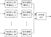
The concrete structure of digital baseband multi-carrier modulator 6 is shown in figure 11 among Fig. 2; It comprises M M/2 times of up-sampler 621_n and M synthesis filter 622_n and summer 623, thereby wherein the effect of M/2 times of up-sampler is to improve M/2 times to symbol sampler speed through between adjacent two incoming symbols, inserting M/2-1 zero.The structure of digital baseband multicarrier demodulator 13 is shown in figure 12 among Fig. 2; It comprises M analysis filter 1321_n and M M/2 times of down-sampler 1322_n, thereby wherein the effect of M/2 times of down-sampler is to take out a symbol symbol sampler speed reduction M/2 doubly through every at a distance from M/2 incoming symbol.The time domain expression formula of the synthesis filter of k branch road and the analysis filter of k branch road is following:
Wherein, k=1 ..., M, f
k(n) impulse response of the synthesis filter of k branch road of expression, its length is N
f+ 1, h
k(n) impulse response of the analysis filter of k branch road of expression, its length is N
f, h
p(n), n=0,1 ..., N
fPrototype low pass filter of-1 expression, length is N
f, here, N
fIt is the integral multiple of M.All synthesis filters and analysis filter all obtain through this prototype filter is carried out index modulation; On frequency domain, see; Frequency response to prototype filter evenly is shifted exactly; The rule of displacement is that to make that the frequency response of each comprehensive (analysiss) filter distributes corresponding one by one with the sub-band of institute service band division, in this execution mode, this means 12 comprehensive (analysis) filters; Be M=12, and the frequency response of adjacent two comprehensive (analysis) filters have half the overlapping.Get N
f=4*M=48; Figure 13 has provided the prototype filter that adopted and the amplitude-frequency response of synthesis filter here, and the amplitude-frequency response of analysis filter is identical with the amplitude-frequency response of corresponding synthesis filter, as can be seen from the figure; The frequency response of adjacent filter has half the overlapping; Thereby transition band width is than broad, thus under the lower situation of exponent number also very big, nearly-60dB of the stopband attenuation of each filter.The sample frequency of each filter is fixed as f
s=W
Total=3.168GHz, the carrier frequency of upconverter 8 and low-converter 11 is fixed as f among Fig. 2
Mix=f
c=7.584GHz; After the signal process digital-to-analogue conversion and up-conversion that then digital baseband multi-carrier modulator 6 is come out from Fig. 2; Just be shifted on the ultra broadband frequency band that will use, k (k=1,2 wherein; ..., M) frequency spectrum of the output signal of individual synthesis filter will be shifted on the k sub-frequency bands.Receiving terminal and transmitting terminal are similar, and the signal spectrum on the k sub-frequency bands will be through being taken out by k analysis filter after the down-conversion.
Because interference is arranged between adjacent sub-bands,, need to eliminate these interference for the simplified equalization device.Under desirable channel condition, can prove, select suitable prototype filter h
p(n), can make system shown in figure 14 reach complete reconstruct, i.e. the output on each road equals the delay of corresponding input, and the interference between the adjacent road is eliminated after getting the real part operation.The bank of filters that is adopted in this execution mode just satisfies the condition of above-mentioned complete reconstruct, and the character of reconstruct makes receiving terminal can use fairly simple equalizer fully.Notice that it is real numbers that complete reconstruction condition requires the input data; And each filter all is plural; To on the corresponding digital sub-band of each filter, transmit real data now; As if this can reduce spectrum efficiency at first sight, but the frequency spectrum of adjacent two-way has half the overlapping, so the availability of frequency spectrum does not descend.
The channel encoder 1 of transmitting terminal adding redundant information in the input data is encoded among Fig. 2, to improve the reliability of transmission.Can select the multiple coded system of various code rate, like convolution code, Turbo code, LDPC sign indicating number etc.The employing constraint length is 7 convolution code in this execution mode, and code rate requires to select 1/3,1/2,5/8 and 3/4 equivalence according to index of correlation.
Bit behind 2 pairs of codings of modulator carries out the constellation point mapping, obtains modulation symbol, can require to adopt M-PSK according to index of correlation, and modulation systems such as M-QAM adopt the QPSK modulation in this execution mode.
Deserializer 3 is assigned to modulation symbol on each branch road; If do not use some sub-band; Then distribute data not on their corresponding branch roads supposes that here all sub-bands all use, and then deserializer 3 converts 1 road serial data stream into M=12 channel parallel data stream.
The framer 4_n on each road divides into groups according to certain format to this circuit-switched data with the parameter of the bank of filters that is adopted according to the parameter of OFDM modulation, thereby and adds configuration frames such as synchronizing symbol sequence, channel estimation symbol sequence, frame head information symbol sequence.Therefore, for specifying framer 4_n, also need the parameter of explanation OFDM modulator earlier.
OFDM modulator 5_n carries out OFDM modulation to every frame data of place branch road, comprises string and conversion, IFFT operation, pended cyclic prefix, and string conversion etc.In this execution mode, the number of sub carrier wave of OFDM is got N=128, and circulating prefix-length is got N
Cyc=37 sample values.In the present embodiment owing to adopted the bank of filters of complete reconstruct, therefore and do not require and insert the gap carrier wave, but because the input of synthesis filter group to require be real number, this just limits the input of OFDM modulator.What sequence of real numbers was carried out that FFT operation obtains is conjugate symmetric sequence, so a series of sequences that the data that require to enter into the OFDM modulator obtain after through string and conversion all are conjugate symmetric sequences.Length N is the conjugate symmetric sequence X (n) of even number, n=1, and 2 ..., N is meant that the sequence that satisfies following condition: X (1), X (N/2+1) they are real numbers, X (n)=X
*(N+2-n), n=2,3 ..., N/2.
Suppose that each frame comprises K on each branch road
DataIndividual OFDM data symbol, fixing K here
Data=100.Then framer 4_n at first selects N*K
Data/ 2=6400 modulation symbol is divided into K with them
Data=100 groups, every group comprises N/2=64 modulation symbol, then each group code is carried out the expansion of conjugation symmetry, and 64 sign extended are become the conjugate symmetric sequence that comprises 128 symbols, and Figure 15 has provided conjugation symmetry expansion sketch map.Put in order after the data, framer 4_n also will insert some synchronizing symbols, channel estimation symbol and frame head information symbol in the front of data sequence, and these symbol sebolic addressings also have conjugate symmetry matter.Final framer 4_n output length is (K
Sync+ K
Est+ K
Header+ K
Data) frame of * N, wherein K
Sync, K
Est, K
Header, K
DataBe respectively synchronizing sequence, channel estimation sequence, frame head information sequence, OFDM symbolic number that data sequence comprised.
Each frame data carries out the modulation second time through digital baseband multi-carrier modulator 6 again through OFDM modulation back institute call sign; Thereby each roadbed band data-modulated to the corresponding digital sub-band; And combine, obtain the digital baseband signal of whole radio frequency band signal.Digital-to-analog converter 7 converts digital signal into analog baseband signal; Upconverter 8 analog baseband signal move the ultra-wide band radio-frequency frequency range that will use, send via antenna 9 then.So just obtained having the transmission signal of double-deck carrier wave.
Receiving terminal reception antenna 10 is from the signal of aerial reception among Fig. 2, through low-converter 11 radiofrequency signal moved base band, converts digital baseband signal into through analog to digital converter 12 again.
13 pairs of above-mentioned baseband signals of digital baseband multicarrier demodulator are decomposed; Take out the signal of respective frequency sub-bands; And it is transformed into the lower base band of sample rate through down-sampling; Obtain the multichannel baseband signal corresponding with transmitting terminal, each road signal has comprised the full detail of corresponding transmitting terminal signal, receives the influence of channel and the interference of adjacent legs signal simultaneously again.
Ofdm demodulator 14_n carries out the OFDM demodulation to every roadbed band signal, and its detailed process comprises string and changes, removes Cyclic Prefix, FFT operation etc.
The function of detector 15_n is that the data after the OFDM demodulation are carried out equilibrium and detection, thereby obtains the estimated value of transmitting terminal modulation symbol.Equalizer be designed with a variety of schemes, adopt a kind of LMS adaptive equalizer in this execution mode based on minimum mean square error criterion, adopt the equalization methods of other adaptive algorithms also to be suitable for the present invention.Balanced effect mainly contains two, and one is that unfavorable channel response is compensated, and another is that the interference of adjacent legs data is eliminated.The use of OFDM makes frequency selective fading channels be converted into a plurality of flat fading channels, so the elimination of channel effect only need use the equalizer of single tap just can accomplish.After channel compensated, just obtained the similar reconfiguration system fully with Figure 14, data are also at the frequency domain of OFDM modulation only now, and do not get the real part operation.Be transformed into time domain if the sequence after the equilibrium is carried out the IFFT operation, and get real part, just obtain the time-domain symbol identical with transmitting terminal; Eliminated the interference of adjacent legs; Carry out FFT operation again, just obtain the frequency domain symbol identical, this balanced just purpose that will reach with transmitting terminal.It is easy to show that aforesaid operations can be reduced to union operation simply in twos.Figure 16 provided k (k=1,2 ....; 12) estimate and detect the concrete structure of i the employed detector of original incoming symbol in a certain OFDM frequency domain symbol on the branch road, i=1 wherein, 2; ..., 64, the sequence number of the modulation symbol before the expansion of conjugation symmetry is carried out in expression.w
K, i(n) in k branch road of expression, the n OFDM symbol period to the coefficient of the equalizer of demodulating data use (N+2-i changes N/2+1 in need be Figure 16 when the i=1) on i the OFDM subcarrier.Detector 15_n is made up of N/2=64 said structure, and with the symbol after the serial mode output detection.
Data after the detection synthesize one the tunnel to multichannel data through parallel-to-serial converter 16 again, deliver to demodulator 17 and carry out symbol demodulation, recover original input data through channel decoder 18 at last.
In this execution mode, be with ultra broadband to compare more, have following advantage with tradition:
1) can reach very high speed, be directly proportional with the institute dedicated bandwidth.If 12 sub-frequency bands are all used, adopt the convolution code of r=1/2 code check, the QPSK modulation, then under the situation of not considering Cyclic Prefix and frame head information sequence etc., the rate of information throughput is about R
Bits=r* (log
24) * M/2*fs/ (M/2)=fs=3.168Gbps;
2) transmitting terminal and receiving terminal only use a frequency converter respectively, have reduced the complexity of radio frequency;
3) configuration of sub-band and switching are all accomplished at numeric field, and frequency band uses flexibly;
4) used comprehensive and analysis filter exponent number is low, and stopband attenuation is big, need not re-use the very high formed filter of exponent number and suppress out-of-band radiation.This also is the advantage of present embodiment with respect to embodiment 1.
More than be two kinds of more basic execution modes of the present invention,, can obviously obtain some similar schemes, all should fall into the scope of the present invention's protection according to content disclosed by the invention.