CN101737411B - hinge structure - Google Patents

hinge structure Download PDF

Info

Publication number
CN101737411B
CN101737411B CN2008103056944A CN200810305694A CN101737411B CN 101737411 B CN101737411 B CN 101737411B CN 2008103056944 A CN2008103056944 A CN 2008103056944A CN 200810305694 A CN200810305694 A CN 200810305694A CN 101737411 B CN101737411 B CN 101737411B
Authority
CN
China
Prior art keywords
sleeve
positioning
rotating shaft
hinge structure
connecting piece
Prior art date
Legal status (The legal status is an assumption and is not a legal conclusion. Google has not performed a legal analysis and makes no representation as to the accuracy of the status listed.)
Expired - Fee Related
Application number
CN2008103056944A
Other languages
Chinese (zh)
Other versions
CN101737411A (en
Inventor
张汉铮
李小波
王金鑫
Current Assignee (The listed assignees may be inaccurate. Google has not performed a legal analysis and makes no representation or warranty as to the accuracy of the list.)
Hongfujin Precision Industry Shenzhen Co Ltd
Hon Hai Precision Industry Co Ltd
Original Assignee
Hongfujin Precision Industry Shenzhen Co Ltd
Hon Hai Precision Industry Co Ltd
Priority date (The priority date is an assumption and is not a legal conclusion. Google has not performed a legal analysis and makes no representation as to the accuracy of the date listed.)
Filing date
Publication date
Application filed by Hongfujin Precision Industry Shenzhen Co Ltd, Hon Hai Precision Industry Co Ltd filed Critical Hongfujin Precision Industry Shenzhen Co Ltd
Priority to CN2008103056944A priority Critical patent/CN101737411B/en
Priority to US12/420,201 priority patent/US8011066B2/en
Publication of CN101737411A publication Critical patent/CN101737411A/en
Application granted granted Critical
Publication of CN101737411B publication Critical patent/CN101737411B/en
Expired - Fee Related legal-status Critical Current
Anticipated expiration legal-status Critical

Links

Images

Classifications

    • GPHYSICS
    • G06COMPUTING OR CALCULATING; COUNTING
    • G06FELECTRIC DIGITAL DATA PROCESSING
    • G06F1/00Details not covered by groups G06F3/00 - G06F13/00 and G06F21/00
    • G06F1/16Constructional details or arrangements
    • G06F1/1613Constructional details or arrangements for portable computers
    • G06F1/1633Constructional details or arrangements of portable computers not specific to the type of enclosures covered by groups G06F1/1615 - G06F1/1626
    • G06F1/1675Miscellaneous details related to the relative movement between the different enclosures or enclosure parts
    • G06F1/1681Details related solely to hinges
    • GPHYSICS
    • G06COMPUTING OR CALCULATING; COUNTING
    • G06FELECTRIC DIGITAL DATA PROCESSING
    • G06F1/00Details not covered by groups G06F3/00 - G06F13/00 and G06F21/00
    • G06F1/16Constructional details or arrangements
    • G06F1/1613Constructional details or arrangements for portable computers
    • G06F1/1615Constructional details or arrangements for portable computers with several enclosures having relative motions, each enclosure supporting at least one I/O or computing function
    • G06F1/1616Constructional details or arrangements for portable computers with several enclosures having relative motions, each enclosure supporting at least one I/O or computing function with folding flat displays, e.g. laptop computers or notebooks having a clamshell configuration, with body parts pivoting to an open position around an axis parallel to the plane they define in closed position
    • G06F1/162Constructional details or arrangements for portable computers with several enclosures having relative motions, each enclosure supporting at least one I/O or computing function with folding flat displays, e.g. laptop computers or notebooks having a clamshell configuration, with body parts pivoting to an open position around an axis parallel to the plane they define in closed position changing, e.g. reversing, the face orientation of the screen with a two degrees of freedom mechanism, e.g. for folding into tablet PC like position or orienting towards the direction opposite to the user to show to a second user

Landscapes

  • Engineering & Computer Science (AREA)
  • Computer Hardware Design (AREA)
  • Theoretical Computer Science (AREA)
  • Physics & Mathematics (AREA)
  • Human Computer Interaction (AREA)
  • General Engineering & Computer Science (AREA)
  • General Physics & Mathematics (AREA)
  • Mathematical Physics (AREA)
  • Pivots And Pivotal Connections (AREA)
  • Telephone Set Structure (AREA)

Abstract

一种铰链结构,其包括第一连接件、第二连接件及枢接第一连接件和第二连接件的枢接组件。枢接组件包括非转动地连接第一连接件的转轴、相对第一连接件固定的套筒及相对第二连接件固定的定位套环。套筒套设于转轴,定位套环可转动地套设于套筒。套筒的侧壁开设有定位孔,定位套环的内圆环边缘形成有与定位孔相配合的定位凸起。定位凸起卡入定位孔内使第一连接件与第二连接件保持相对稳定,且受外力时套筒和定位套环的至少其中之一发生弹性变形,使定位凸起可从定位孔内滑出以使第一连接件与第二连接件可相对转动。本发明铰链结构的元件数量较少且结构较为简单。

Figure 200810305694

A hinge structure, which includes a first connecting piece, a second connecting piece and a pivot assembly pivotally connecting the first connecting piece and the second connecting piece. The pivot assembly includes a rotating shaft non-rotatably connected to the first connecting part, a sleeve fixed relative to the first connecting part, and a positioning collar fixed relative to the second connecting part. The sleeve is sleeved on the rotating shaft, and the positioning collar is rotatably sleeved on the sleeve. A positioning hole is opened on the side wall of the sleeve, and a positioning protrusion matched with the positioning hole is formed on the edge of the inner ring of the positioning collar. The positioning protrusion snaps into the positioning hole so that the first connecting piece and the second connecting piece remain relatively stable, and at least one of the sleeve and the positioning collar undergoes elastic deformation when an external force is applied, so that the positioning protrusion can be removed from the positioning hole. Slide out so that the first connecting part and the second connecting part can rotate relatively. The hinge structure of the present invention has fewer components and a simpler structure.

Figure 200810305694

Description

Hinge structure
Technical field
The invention relates to a kind of hinge structure, especially less the and comparatively simple hinge structure of structure about a kind of number of elements.
Background technique
Along with the development of electronic product towards the light direction, require each supporting with it modular construction more and more simpler, thereby alleviate the weight of electronic product, be easy to carry.
A kind of electronic product, the hinge structure that it comprises lid, body and articulates lid and body.Hinge structure comprises a fixed base, a friction plate, a support, a stationary cam, rotating cam, shell fragment group, flat gasket group, a nut and a pivot.Stationary cam comprises a plurality of grooves, and rotating cam comprises a plurality of convexities, and the groove of stationary cam is used for matching with the convexity of rotating cam.Fixed base is fixed in the body of electronic equipment, and support is fixed in the lid of electronic equipment, and the shell fragment group is used to provide axial pressure.Pivot one end is fixed in support; The other end inserts fixed base, friction plate, stationary cam, rotating cam, shell fragment group and flat gasket group successively; And nut is fixed in the pivot end; Thereby fixed base, friction plate, support, stationary cam, rotating cam, shell fragment group, flat gasket group can not be broken away from each other, and support, rotating cam can not be sheathed on to pivot relative pivot, stationary cam then is fixed in fixed base.
In the hinge structure of above-mentioned electronic equipment, more this hinge structure that makes of number of elements is comparatively complicated, and need expend more cost of material and processing cost.
Summary of the invention
In view of foregoing, be necessary to provide a kind of number of elements the less and comparatively simple hinge structure of structure.
A kind of hinge structure, it comprises first link, second link and articulates first link and the pin connected assembly of second link.Pin connected assembly comprises the positioning ring that the rotating shaft that connects first link non-rotatingly, the relative first link stationary sleeve and relative second link are fixing.Jacket casing is located at rotating shaft, and positioning ring can be sheathed on sleeve rotationally.The sidewall of sleeve offers positioning hole, and the interior annulus edge of positioning ring is formed with the positioning convex that matches with positioning hole.Positioning convex snaps in first link and second link is kept relative stability; And one of them generation resiliently deformable at least of sleeve and positioning ring can skid off so that first link and second link can relatively rotate positioning convex when receiving external force in positioning hole.
In the above-mentioned hinge structure; One of them generation resiliently deformable at least of sleeve or positioning ring; Make the positioning hole of sleeve cooperate and realize rotation positioning that need not to be provided with the shell fragment group provides elastic force to make hinge structure can rotate the location with the positioning convex of positioning ring.Thereby above-mentioned hinge structure number of elements is less, and each element structure of above-mentioned hinge structure is comparatively simple, thereby is convenient to assembling and manufacturing, and then reduces production costs.
Description of drawings
Fig. 1 is the stereogram of electronic equipment of using the hinge structure of the embodiment of the invention.
Fig. 2 is the part three-dimensional exploded view of the hinge structure among Fig. 1.
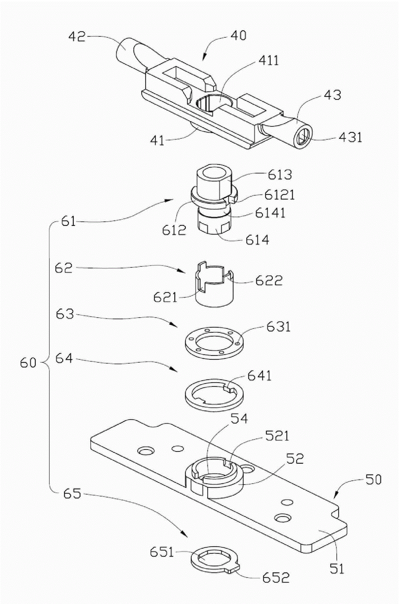
Fig. 3 is the three-dimensional exploded view at another visual angle of hinge structure shown in Figure 2.
Fig. 4 is the three-dimensional assembly diagram of hinge structure shown in Figure 2.
Fig. 5 is the three-dimensional assembly diagram at another visual angle of hinge structure shown in Figure 4.
Embodiment
To combine accompanying drawing and embodiment that hinge structure of the present invention is done further to specify below.
Shown in Figure 1 is the electronic equipment 200 that is equipped with the hinge structure 100 of the embodiment of the invention, and it comprises lid 11 and body 12.Hinge structure 100 is used to articulate lid 11 and body 12, and the lid 11 that makes electronic equipment 200 body 12 relatively rotates around axis A.
Please consult Fig. 2 and Fig. 3 simultaneously, hinge structure 100 comprises first link 40, second link 50 and articulates the pin connected assembly 60 of first link 40 and second link 50.Pin connected assembly 60 is arranged at first link, 40 middle parts and vertical first link 40.First link 40 is fixedly connected with the lid 11 of electronic equipment 200.Second link 50 is fixedly connected with the body 12 of electronic equipment 200.Certainly, also can first link 40 connect the body 12 of electronic equipments 200, and second link 50 connects the lid 11 of electronic equipments 200.
First link 40 roughly is the T font, the joint 42,43 that it has body 41 and forms along the extension of body 41 bilateral symmetry.Body 41 and joint 42,43 offer mounting hole 411,421,431 respectively.Wherein, mounting hole 421,431 coaxial settings, and the intersect vertical axis of its axis and mounting hole 411.
Second link 50 comprises that a plat part 51, one are positioned at plat part 51 middle parts and the annulus portion 52 that extends to form from the one side of plat part 51, are opened in plat part 51 another sides and restraining groove 53 and through hole 54 of running through plat part 51 and annulus portion 52 relative with annulus portion 52.Offer a plurality of mounting holes (figure mark) on the plat part 51, so that second link 50 is fixed in the body 12 of electronic equipment 200.Offer two in the annulus portion 52 and hold mouth 521.Restraining groove 53 is roughly circle, and it has two limited parts 531.
Pin connected assembly 60 comprises a rotating shaft 61, sleeve 62, friction plate 63, a positioning ring 64 and a bounding means 65.
Assembly department 613 and axle portion 614 that rotating shaft 61 comprises flange 612, extends to form to two ends vertically from flange 612.Offer two draw-in grooves 6121 on the flange 612.The shape of cross section of assembly department 613 is corresponding with the shape of the mounting hole 411 of first link 40, so that after assembly department 613 was arranged in the mounting hole 411, rotating shaft 61 can be rotated with first link 40.Axle portion 614 ends have a plurality of tangent planes (figure is mark not), so that axle portion 614 terminal lateral cross section are abnormity.Also offer the annular groove 6141 of an adjacent flange 612 on the axle portion 614.Certainly, rotating shaft 61 can be shaped in the body 41 of first link 40.
Offer two positioning holes 621 on sleeve 62 sidewalls.In the present embodiment, positioning hole 621 is for being opened in the breach of sleeve 62 1 ends.Sleeve 62 1 ends are formed with two and hold lug 622, hold lug 622 and are used to snap in the draw-in groove 6121 of rotating shaft 61 so that sleeve 62 phase countershafts 61 are non-rotatable, and then make sleeve 62 relative first links 40 non-rotatable.Also offer a through hole 623 that runs through its sidewall on the sleeve 62.In the present embodiment, resiliently deformable can take place in sleeve 62.
Offer a plurality of oilholes 631 on the friction plate 63, oilhole 631 is used to inject lubricant oil, to reduce the friction between rotating shaft 61 and the positioning ring 64.
The interior annulus edge of positioning ring 64 protrudes out the positioning convex 641 that forms two symmetries to the center of circle.What the positioning convex 641 of positioning ring 64 was used to be fastened in second link 50 holds mouthfuls 521; Thereby make positioning ring 64 relative second links 50 non-rotatable; Simultaneously, positioning convex 641 hold second link 50 hold mouthfuls 521 after cooperate with the positioning hole 621 of sleeve 62 again.Certainly, also can make positioning ring 64 relative first links 40 non-rotatable, then relative second link 50 of sleeve 62 is non-rotatable.
Bounding means 65 centers offer a through hole 651, the lateral cross section shape of axle portion 614 ends of the corresponding rotating shaft 61 of the shape of through hole 651.Bounding means 65 edges have protruded out a spacing preiection 652, and spacing preiection 652 is used for cooperating to limit the angle of swing of hinge structure 100 with the limited part 531 of restraining groove 53.
Please consult Fig. 4 and Fig. 5 simultaneously, during assembling, the assembly department 613 of rotating shaft 61 is fixed in the mounting hole 411 of first link 40, the axle portion 614 of rotating shaft 61 is inserted sleeve 62, friction plate 63, positioning ring 64, second link 50 and bounding means 65 successively.At this moment, the lug 622 that holds of sleeve 62 is stuck in the draw-in groove 6121 of rotating shaft 61, and sleeve 62 is sheathed in the rotating shaft 61, thereby sleeve 62 can be towards annular groove 6141 direction generation resiliently deformables; The positioning convex 641 of positioning ring 64 passes holding in mouthfuls 521 and being fastened in the positioning hole 621 of sleeve 62 of second link 50; Bounding means 65 is contained in the restraining groove 53 of second link 50, and the spacing preiection 652 of bounding means 65 is against one of them limited part 531 of living restraining groove 53.
During use, pull the lid 11 of electronic equipment 200, make body 12 rotations of lid 11 relative electronic equipments 200, this moment, the rotation of lid 11 drove 40 rotations of first link, and then drove rotating shaft 61 rotations.Because sleeve 62 phase countershafts 61 are non-rotatable; And sleeve 62 can be towards the annular groove 6141 direction generation resiliently deformables of rotating shaft 61; Positioning ring 64 relative second links 50 are non-rotatable; Thereby when rotating shaft 61 rotations, the positioning convex 641 of positioning ring 64 can skid off the positioning hole 621 of sleeve 62 and be held in the surface of sleeve 62, makes sleeve 62 that resiliently deformable take place.When rotating shaft 61 rotated to several angle, the positioning convex 641 of positioning ring 64 was snapped in the positioning hole 621 of sleeve 62 once more, realized rotation positioning, and at this moment, sleeve 62 recovers deformation.When turning an angle once more, the spacing preiection 652 of bounding means 65 stops hinge structure 100 further to rotate against a limited part 531 of living restraining groove 53.
In the hinge structure 100 of above-mentioned electronic equipment 200; The positioning convex 641 of positioning ring 64 matches with the positioning hole 621 of sleeve 62; And because axle portion 614 has annular groove 6141; Thereby sleeve 62 can be towards the annular groove 6141 direction generation resiliently deformables of rotating shaft 61 so that sleeve 62 is realized rotation positioning when cooperating with positioning ring 64, need not to be provided with the shell fragment group provides elastic force to make hinge structure 100 can rotate the location again, also need not to be provided with stationary cam and rotating cam and realizes locating.
In addition, the friction between positioning ring 64 and the sleeve 62 can provide stable torsion, need not to be provided with shim pack again.Thereby the number of elements of hinge structure 100 is less, and each element structure of hinge structure 100 is comparatively simple, thereby is convenient to assembling and manufacturing, thereby reduces production costs.Certainly, can swivel assembly be installed in the joint 42,43 of first link 40, so that electronic equipment 200 can be realized the folding of lid 11 relative bodies 12 simultaneously.In addition, on the axle portion 614 annular groove 6141 can be set, the diameter that makes the diameter of sleeve 62 be a bit larger tham axle portion 614 gets final product.
Be appreciated that the positioning hole 621 on the sleeve 62 also can be through hole or groove etc.In addition, through positioning ring 64 rotation positioning that resiliently deformable can realize hinge structure 100 equally takes place.In addition, positioning ring 64 can be located in the sleeve 62 and be fixed in second link 50, makes positioning convex 641 be formed at positioning ring 64 edges and gets final product.
Be appreciated that hinge structure 100 of the present invention can be used for realizing the folding of the lid 11 relative bodies 12 of electronic equipment 200.
In addition, those skilled in the art also can do other variation in spirit of the present invention, and certainly, these all should be included in the present invention's scope required for protection according to the variation that the present invention's spirit is done.

Claims (9)

1.一种铰链结构,其包括第一连接件、第二连接件及枢接该第一连接件和第二连接件的枢接组件,该枢接组件包括非转动地连接该第一连接件的转轴,其特征在于:该枢接组件进一步包括相对该第一连接件固定的套筒及相对该第二连接件固定的定位套环,该套筒套设于该转轴,该定位套环能够转动地套设于该套筒,该套筒的侧壁开设有定位孔,该定位套环的内圆环边缘形成有与该定位孔相配合的定位凸起,该定位凸起卡入该定位孔内使该第一连接件与该第二连接件保持相对稳定,且受外力时该套筒和该定位套环的至少其中之一发生弹性变形,使该定位凸起能够从该定位孔内滑出以使该第一连接件与该第二连接件能够相对转动。1. A hinge structure comprising a first connecting piece, a second connecting piece, and a pivot assembly pivotally connecting the first connecting piece and the second connecting piece, the pivoting assembly comprising a non-rotatably connected first connecting piece The rotating shaft is characterized in that: the pivot assembly further includes a sleeve fixed relative to the first connecting piece and a positioning collar fixed relative to the second connecting piece, the sleeve is sleeved on the rotating shaft, and the positioning collar can It is rotatably sleeved on the sleeve, and the side wall of the sleeve is provided with a positioning hole, and the inner ring edge of the positioning collar is formed with a positioning protrusion matching the positioning hole, and the positioning protrusion snaps into the positioning The first connecting piece and the second connecting piece are kept relatively stable in the hole, and at least one of the sleeve and the positioning collar is elastically deformed when an external force is applied, so that the positioning protrusion can be removed from the positioning hole. slide out so that the first connecting part and the second connecting part can rotate relative to each other. 2.如权利要求1所述的铰链结构,其特征在于:该套筒的直径稍大于该转轴的直径以使该套筒套于该转轴后能够朝该转轴方向发生弹性变形。2 . The hinge structure as claimed in claim 1 , wherein a diameter of the sleeve is slightly larger than a diameter of the rotating shaft so that the sleeve can elastically deform toward the rotating shaft after being fitted on the rotating shaft. 3 . 3.如权利要求1所述的铰链结构,其特征在于:该转轴上开设有环形凹槽以使该套筒套设于该转轴后该套筒能够朝该转轴的环形凹槽方向发生弹性变形。3. The hinge structure according to claim 1, wherein an annular groove is formed on the rotating shaft so that the sleeve can elastically deform toward the annular groove of the rotating shaft after the sleeve is sleeved on the rotating shaft . 4.如权利要求3所述的铰链结构,其特征在于:该转轴包括一个凸缘,该凸缘上开设有卡槽,该套筒的一端形成有卡持凸片,该卡持凸片卡持入该转轴的卡槽内以使该套筒相对该转轴非可转动。4. The hinge structure according to claim 3, characterized in that: the rotating shaft comprises a flange, and a locking groove is opened on the flange, and a locking tab is formed on one end of the sleeve, and the locking tab engages The sleeve is held in the slot of the rotating shaft so that the sleeve is non-rotatable relative to the rotating shaft. 5.如权利要求1所述的铰链结构,其特征在于:该定位孔为开设于该套筒一端的缺口,或开设于该套筒的通孔或凹槽。5 . The hinge structure according to claim 1 , wherein the positioning hole is a notch opened at one end of the sleeve, or a through hole or a groove opened at the sleeve. 5 . 6.如权利要求1所述的铰链结构,其特征在于:该转轴一体成型于该第一连接件。6. The hinge structure as claimed in claim 1, wherein the rotating shaft is integrally formed on the first connecting member. 7.如权利要求1所述的铰链结构,其特征在于:该铰链结构进一步包括摩擦片,该摩擦片套设于该转轴,该摩擦片上开设有油孔,油孔用于注入润滑油以减小定位套环和转轴之间的摩擦。7. The hinge structure according to claim 1, characterized in that: the hinge structure further comprises a friction plate, the friction plate is sheathed on the rotating shaft, an oil hole is opened on the friction plate, and the oil hole is used for injecting lubricating oil to reduce the friction. Friction between the small retaining collar and the shaft. 8.如权利要求1所述的铰链结构,其特征在于:该第二连接件包括一个平板部、一个位于平板部中部且从平板部的一面延伸形成的圆环部,圆环部上开设有卡持口,该定位套环的定位凸起卡扣于该卡持口以使该定位套环相对该第二连接件非可转动。8. The hinge structure according to claim 1, characterized in that: the second connecting member comprises a flat plate part, an annular part located in the middle of the flat plate part and extending from one side of the flat plate part, and the annular part is provided with The locking opening, the positioning projection of the positioning collar is buckled in the locking opening so that the positioning collar is non-rotatable relative to the second connecting member. 9.如权利要求8所述的铰链结构,其特征在于:该铰链结构进一步包括一个限位件,该第二连接件进一步包括开设于平板部中部的另一面且和圆环部相对的限位槽,该限位槽具有限位部,该限位件边缘凸伸形成有限位凸起,该限位件套设于该转轴并容纳于该限位槽,且该限位凸起与该限位部配合以限制该铰链结构的旋转角度。9. The hinge structure according to claim 8, characterized in that: the hinge structure further comprises a limiter, and the second connecting member further comprises a limiter set on the other side of the middle part of the flat plate and opposite to the ring portion slot, the limiting slot has a limiting portion, the edge of the limiting member protrudes to form a limiting protrusion, the limiting member is sleeved on the rotating shaft and accommodated in the limiting groove, and the limiting protrusion and the limiting The bit parts cooperate to limit the rotation angle of the hinge structure.
CN2008103056944A 2008-11-21 2008-11-21 hinge structure Expired - Fee Related CN101737411B (en)

Priority Applications (2)

Application Number Priority Date Filing Date Title
CN2008103056944A CN101737411B (en) 2008-11-21 2008-11-21 hinge structure
US12/420,201 US8011066B2 (en) 2008-11-21 2009-04-08 Hinge assembly for electronic device

Applications Claiming Priority (1)

Application Number Priority Date Filing Date Title
CN2008103056944A CN101737411B (en) 2008-11-21 2008-11-21 hinge structure

Publications (2)

Publication Number Publication Date
CN101737411A CN101737411A (en) 2010-06-16
CN101737411B true CN101737411B (en) 2012-03-28

Family

ID=42194876

Family Applications (1)

Application Number Title Priority Date Filing Date
CN2008103056944A Expired - Fee Related CN101737411B (en) 2008-11-21 2008-11-21 hinge structure

Country Status (2)

Country Link
US (1) US8011066B2 (en)
CN (1) CN101737411B (en)

Families Citing this family (11)

* Cited by examiner, † Cited by third party
Publication number Priority date Publication date Assignee Title
CN101907123A (en) * 2009-06-02 2010-12-08 鸿富锦精密工业(深圳)有限公司 hub
CN102809033B (en) * 2011-05-30 2015-06-24 鸿富锦精密工业(深圳)有限公司 Supporting device
TWI435007B (en) * 2011-12-23 2014-04-21 Wistron Corp Biaxial pivoting mechanism and electronic device thereof
WO2015045131A1 (en) * 2013-09-27 2015-04-02 富士通株式会社 Electronic apparatus and hinge unit
US9696754B2 (en) * 2014-03-26 2017-07-04 Intel Corporation Hinge having multiple degrees of freedom
US20150277490A1 (en) * 2014-03-28 2015-10-01 Kenneth Jasinski Electronic device
CN106088882B (en) * 2016-07-27 2018-02-27 广州市巨安人防工程有限公司 Hinge for revolving door
CN106151840A (en) * 2016-08-30 2016-11-23 苏州市顺仪五金有限公司 A kind of rotary connector
CN109538624B (en) * 2019-01-15 2023-10-31 北京史河科技有限公司 Hinge device and mechanical equipment with same
CN109856812A (en) * 2019-04-10 2019-06-07 温州市冠豪眼镜有限公司 A kind of telescopically adjustable earpiece
CN118202316A (en) * 2021-11-04 2024-06-14 三星电子株式会社 Electronic device including hinge assembly

Citations (3)

* Cited by examiner, † Cited by third party
Publication number Priority date Publication date Assignee Title
CN1702777A (en) * 2005-07-08 2005-11-30 诚龙企业有限公司 Hinge structure to adjust the display unit to maintain any position
CN2814875Y (en) * 2005-08-02 2006-09-06 朱庆涛 Rotary hinge
TWM304715U (en) * 2006-06-23 2007-01-11 Quanta Comp Inc Hinge device with auto-lock function

Family Cites Families (12)

* Cited by examiner, † Cited by third party
Publication number Priority date Publication date Assignee Title
GB2279105B (en) * 1993-06-16 1996-09-25 Gsl Res Technology Ltd Hinge device
JP2002266841A (en) * 2001-03-13 2002-09-18 Nhk Sales Co Ltd Tilt hinge
KR100414670B1 (en) * 2001-11-28 2004-01-13 삼성전자주식회사 Hinge device
CN1279418C (en) * 2001-12-24 2006-10-11 Lg电子株式会社 Hinge assemblies for flat panel display devices
KR100500234B1 (en) * 2002-11-05 2005-07-11 삼성전자주식회사 Display apparatus
JP2005208428A (en) * 2004-01-23 2005-08-04 Sony Corp Rotating hinge mechanism and imaging device
CN2691216Y (en) * 2004-02-03 2005-04-06 安普新股份有限公司 Pivot structure
JPWO2006035757A1 (en) * 2004-09-30 2008-05-15 日本発条株式会社 Hinge device and opening / closing mechanism using the hinge device
KR100663445B1 (en) * 2005-11-30 2007-01-02 삼성전자주식회사 Hinge device of a portable terminal
CN100467891C (en) * 2005-12-01 2009-03-11 鸿富锦精密工业(深圳)有限公司 hinge device
US7707691B2 (en) * 2006-05-25 2010-05-04 Lg Electronics Inc. Hinge assembly for electronic appliance and stand apparatus having the same
US7743468B2 (en) * 2007-11-13 2010-06-29 Shin Zu Shing Co., Ltd. Hinge assembly

Patent Citations (3)

* Cited by examiner, † Cited by third party
Publication number Priority date Publication date Assignee Title
CN1702777A (en) * 2005-07-08 2005-11-30 诚龙企业有限公司 Hinge structure to adjust the display unit to maintain any position
CN2814875Y (en) * 2005-08-02 2006-09-06 朱庆涛 Rotary hinge
TWM304715U (en) * 2006-06-23 2007-01-11 Quanta Comp Inc Hinge device with auto-lock function

Also Published As

Publication number Publication date
CN101737411A (en) 2010-06-16
US20100125975A1 (en) 2010-05-27
US8011066B2 (en) 2011-09-06

Similar Documents

Publication Publication Date Title
CN101737411B (en) hinge structure
EP3699728B1 (en) Hinge module and foldable electronic device including the same
US20160224072A1 (en) Hinge mechanism and portable electronic device
US6317927B1 (en) Hinge device
US6223393B1 (en) Redundant hinge element for a notebook computer
US8353776B2 (en) Universal ball joint
US9448583B1 (en) Electronic device and hinge assembly
CN101871485B (en) Hinge structure
CN101311875B (en) CD ROM baffle plate combination
US20100139042A1 (en) Hinge and collapsible device utilizing the same
US20140059805A1 (en) Friction hinge system
CN102619866A (en) Hinge structure
CN101625009A (en) Hinge structure
CN201277256Y (en) Pivotal device
EP3936734B1 (en) Chain unit, hinge, and mobile terminal
US20160216744A1 (en) Hinge and an electronic device incorporating the same
CN111357394B (en) Folding mechanism and electronic device
CN101725622A (en) Hinge structure
CN105299409B (en) Support frame
CN201496397U (en) hub
CN113508237A (en) Electronic device with hinge assembly
CN101105199A (en) Inclined hinge and electric device
US20160113133A1 (en) Housing locking apparatus
CN101644298A (en) Hinge structure and electronic device adopting same
CN101725623A (en) Hub device

Legal Events

Date Code Title Description
C06 Publication
PB01 Publication
C10 Entry into substantive examination
SE01 Entry into force of request for substantive examination
C14 Grant of patent or utility model
GR01 Patent grant
CF01 Termination of patent right due to non-payment of annual fee

Granted publication date: 20120328

Termination date: 20141121

EXPY Termination of patent right or utility model