CN101675285B - Method for manufacturing elongated multi-layer Tubular body - Google Patents
Method for manufacturing elongated multi-layer Tubular body Download PDFInfo
- Publication number
- CN101675285B CN101675285B CN200880014762.XA CN200880014762A CN101675285B CN 101675285 B CN101675285 B CN 101675285B CN 200880014762 A CN200880014762 A CN 200880014762A CN 101675285 B CN101675285 B CN 101675285B
- Authority
- CN
- China
- Prior art keywords
- inner sleeve
- elongated
- metal
- band
- layer
- Prior art date
- Legal status (The legal status is an assumption and is not a legal conclusion. Google has not performed a legal analysis and makes no representation as to the accuracy of the status listed.)
- Expired - Fee Related
Links
Images


Classifications
-
- F—MECHANICAL ENGINEERING; LIGHTING; HEATING; WEAPONS; BLASTING
- F16—ENGINEERING ELEMENTS AND UNITS; GENERAL MEASURES FOR PRODUCING AND MAINTAINING EFFECTIVE FUNCTIONING OF MACHINES OR INSTALLATIONS; THERMAL INSULATION IN GENERAL
- F16L—PIPES; JOINTS OR FITTINGS FOR PIPES; SUPPORTS FOR PIPES, CABLES OR PROTECTIVE TUBING; MEANS FOR THERMAL INSULATION IN GENERAL
- F16L9/00—Rigid pipes
- F16L9/02—Rigid pipes of metal
- F16L9/04—Reinforced pipes
- F16L9/042—Reinforced pipes the reinforcement comprising one or more layers of a helically wound cord, wire or strip
-
- B—PERFORMING OPERATIONS; TRANSPORTING
- B21—MECHANICAL METAL-WORKING WITHOUT ESSENTIALLY REMOVING MATERIAL; PUNCHING METAL
- B21C—MANUFACTURE OF METAL SHEETS, WIRE, RODS, TUBES, PROFILES OR LIKE SEMI-MANUFACTURED PRODUCTS OTHERWISE THAN BY ROLLING; AUXILIARY OPERATIONS USED IN CONNECTION WITH METAL-WORKING WITHOUT ESSENTIALLY REMOVING MATERIAL
- B21C37/00—Manufacture of metal sheets, rods, wire, tubes, profiles or like semi-manufactured products, not otherwise provided for; Manufacture of tubes of special shape
- B21C37/06—Manufacture of metal sheets, rods, wire, tubes, profiles or like semi-manufactured products, not otherwise provided for; Manufacture of tubes of special shape of tubes or metal hoses; Combined procedures for making tubes, e.g. for making multi-wall tubes
- B21C37/12—Making tubes or metal hoses with helically arranged seams
- B21C37/123—Making tubes or metal hoses with helically arranged seams of coated strip material; Making multi-wall tubes
-
- F—MECHANICAL ENGINEERING; LIGHTING; HEATING; WEAPONS; BLASTING
- F16—ENGINEERING ELEMENTS AND UNITS; GENERAL MEASURES FOR PRODUCING AND MAINTAINING EFFECTIVE FUNCTIONING OF MACHINES OR INSTALLATIONS; THERMAL INSULATION IN GENERAL
- F16L—PIPES; JOINTS OR FITTINGS FOR PIPES; SUPPORTS FOR PIPES, CABLES OR PROTECTIVE TUBING; MEANS FOR THERMAL INSULATION IN GENERAL
- F16L9/00—Rigid pipes
- F16L9/12—Rigid pipes of plastics with or without reinforcement
- F16L9/127—Rigid pipes of plastics with or without reinforcement the walls consisting of a single layer
- F16L9/128—Reinforced pipes
Landscapes
- Engineering & Computer Science (AREA)
- General Engineering & Computer Science (AREA)
- Mechanical Engineering (AREA)
- Rigid Pipes And Flexible Pipes (AREA)
- Laminated Bodies (AREA)
- Bending Of Plates, Rods, And Pipes (AREA)
Abstract
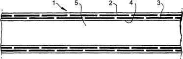
Process for the manufacture of an elongated, multilayered tubular body (1) comprising an elongated, tubular inner hollow core (5), optionally an elongated, tubular inner casing (4) and an elongated, tubular outer casing, the inner casing, when present, surrounding the hollow core, the outer casing surrounding the inner casing, when present, or otherwise the hollow core, the outer casing comprising at least two layers (2, 3), each layer consisting of one or more longitudinally preformed, flat elongated metal strips, the preforming of the strips such that the strips have been bent helically in such a way that the consecutive windings of the helix or helices touch or almost touch to each other, each strip in one layer overlapping with other strips in other layers, the layers in the outer casing being bound to each other by an adhesive.
Description
Technical field
The present invention relates to a kind of method that is used to make tubular body.More particularly; The present invention relates to the manufacturing of elongated multilayer tubular body; This elongated multilayer tubular body comprises elongated inner hollow core, elongated inner sleeve and elongated outer sleeve; Inner sleeve is around hollow, and outer sleeve is around inner sleeve, and outer sleeve comprises two-layer at least longitudinally preformed flat metal band.The preforming of metal band comprises that the bending metals band is so that every metal band becomes spiral through plastic deformation especially.Preformed metal band can for example be processed by high tensile steel, and the steel that particularly is in martensitic phase by the significant proportion in its material is processed.Inner sleeve can for example be processed by corrosion-resistant material.The advantage that this tubular body has is that the pipe with less wall thickness can bear high interior the pressure, thereby the lighter tubular body of weight can bear high interior the pressure.
Background technique
Usually, advantageously, in the standard of keeping the maximum allowable pressure that pipeline can operate, manage to make (every meter) pipeline weight minimum.Perhaps, in other words, advantageously, when the maintenance of (every meter) weight is identical, increase the maximum allowable pressure that pipeline can be operated.Thereby cost of material can significantly be practiced thrift, and cost of transportation also obtains practicing thrift simultaneously.
Be known that rock gas and petroleum liquid product possibly comprise undesirable pollutant, particularly undesirable acid contaminant is such as carbon dioxide and hydrogen sulfide.In addition, also possibly there are organic acid and chloride.It is also known that under the pressure and temperature operational condition of standard, transporting pipeline this contaminated product, that formed by conventional material can be for example owing to stress-corrosion cracking is damaged.This damage can cause the crackle that extends longitudinally of pipeline.
The previous trial in order to reduce this damage risk comprises the use corrosion inhibitor, and this corrosion inhibitor just is added in the product that is transported by pipeline.Unfortunately, possibly cause unacceptable cost like this, not only comprise inhibitory agent and add inhibitory agent in the product cost, and be included in the cost of from the product that pipeline transported, removing and reclaim corrosion inhibitor proper time.If because corrosion inhibitor leaks out from pipeline and can cause potential environmental problem, it also is worthless therefore using corrosion inhibitor, particularly at sea in the pipeline.
Tensile stress on the part that has proposed to contact through the contaminated product that reduces to manage be transported reduces the various alternative of the risk of tracheal rupture (particularly stress-corrosion cracking).These alternative comprise the pipe that use is formed by for example two tubes; One in the said two tubes is inserted another root inside; Manage in manufacture process, forcing through machinery type then and contact with outer tube, outer tube has tensile stress so that interior pipe has pressure stress after accomplishing this operation.This method is called as " autofrettage ", U.S. Pat 4,823, and 847 have described a kind of mode of carrying out this operation through machinery type.What will be appreciated that is, if make of two pipes can insert in another root pipe and carry out the autofrettage step and can impair interior pipe sharply, then must these two control be caused to have tolerance very closely.What it is also recognized that is, this special autofrettage operation is only applicable to the pipe of little length, and has to belong to and carry out consuming time and thereby the shortcoming of the operation of expensive.Another shortcoming of producing pipeline with the pipe (normally 8-10 rice is long) of this little length is that it will comprise a lot of joints of formation, and these joints self are ducted weak spots.
From U.S. Pat 4,657, a kind of different types of tubular body of cicada in 049, wherein metal band twines and embeds with the overlap mode spiral in the adhesive matrix to produce rigid tubular structure.U.S. Pat 3,530,567 have described and have a kind ofly brought the method that forms pipe through twining metal bar from overlapping mode spiral, make the pipe thickness at any point place form by a plurality of overlapping.Spiral ridge on the endoporus of the pipe that forms for the edge of removing by metal band, after twining through making this tubular structure expansion make overlapping one of stripping to head on a flattening above the yield point of metal band.There is sizable manufacturing difficulty in this process.
GB2280889 discloses a kind of method that forms the elongated or tubular body of hollow, and this method comprises to twine at least one root timber material band from overlapping mode spiral so that multilayer tubular structures to be provided.In this was provided with, longitudinally preforming was to provide the lateral cross section with at least one step for band, and said at least one step holds the lap of next circle in each circle of this band.Have by the tubular body of a plurality of overlapping wall thickness that form thereby can be processed continuously by single material bands, wall thickness is basically than the big beam thickness of number of the step that in the cross section of this band, forms.WO2006/016190 has described a kind of similar tubular body.
Producing preformedly needs special-purpose, expensive, heavy and equipment power consumption from overlapping band.In addition, this method is quite responsive, and causes producing the stress concentrated (being represented by fatiguestrength reduction factor) that possibly weaken pipe intensity.Make the bar band bending of moulding cause the stress distribution on this band inhomogeneous, possibly cause early failue.When making and use the elongated tubular element, this point is especially unfavorable.
Summary of the invention
The purpose of this invention is to provide a kind of tubular body and forming method thereof, wherein reduced the risk of stress-corrosion cracking, and eliminated one or more in other above-mentioned shortcomings of known tubes and forming method thereof.This new tubular body comprises two or more simple relatively preforming metal bands, preferably round lighter inner sleeve.This preforming metal band is simple, flat prebuckling band, has no abnormal shape.Prebuckling causes forming spiral-shaped.Preforming metal band in the finished product tubular body is not from overlapping.Inner sleeve is preferably erosion-resisting.Like this, the corrosion resistance of pipeline is at least partly separated with requirement of strength.Inner sleeve provides corrosion resistance especially, and skin provides the major component of intensity (axially and radially).The hollow at slender body center is the space that is used to transmit gas and/or liquid.
Therefore, according to the present invention, a kind of method of making elongated multilayer tubular body is provided; This elongated multilayer tubular body comprises elongated tubular inner hollow core, elongated tubulose inner sleeve and elongated jacket tube pipe, and inner sleeve is around hollow, and outer sleeve is around inner sleeve; Outer sleeve comprises two-layer at least; Each layer comprises that all one or more longitudinally preformed flat elongated metal strip, the preforming of metal band make band become to make the continuous pitch of the laps of one or more spirals contact with each other that by helical buckling each root band and other band in other layer in one deck are overlapping; Layer in the outer sleeve adheres to each other through tackiness agent
This method comprises: elongated inner sleeve is provided; One or more first flat elongated metal strip is provided; Make said one or more first metal band plasticity preforming to obtain one or more spirals with bending method; And said one or more preformed first metal bands are applied on the inner sleeve to form the first layer of outer sleeve; Provide and apply tackiness agent, one or more second flat elongated metal strip is provided, make said one or more second metal band plasticity preforming to obtain one or more spirals with bending method; And said preformed one or more second metal band is applied on the first layer of outer sleeve to form the second layer of outer sleeve
Wherein, said preformed flat elongated metal strip is processed through making flat elongated metal strip plastic deformation in the rollforming case, and said rollforming case comprises arbor assembly, and
Said band is supplied to said rollforming case via induction element, and said induction element comprises the elongated case that is provided with elongate slit, and the width of this slit is less times greater than metal band.
Alternatively, before said one or more first metal band being applied on the inner sleeve, layer of adhesive is applied on the said inner sleeve.
Alternatively, said inner sleeve is non-rotary inner sleeve, and the metal bar belt is applied on the said inner sleeve through twining metal band around inner sleeve.
Alternatively, said inner sleeve is processed by thin flat sheet of metal with continuous mode through following process: tinsel is rolled into pipe, vertically welds the tinsel after the rolling subsequently, and good pipe is connected to each other to make welding.
Alternatively, inner sleeve is processed by thin flat sheet of metal with continuous mode through following process described in: suppress, vertically weld the tinsel after the rolling subsequently, and good pipe is connected to each other to make welding.
Alternatively, said inner sleeve twines the flat metal band through spiral and welds the metal band that winds and process with continuous mode.
Alternatively, the arbor assembly that comprises of said rollforming case has 2-5 axle.
Alternatively, the width of this slit than the width of metal band greatly until 2mm.
Alternatively, the slit of said induction element comprises two row's roller or bearings, and to guide said flat elongated metal strip, this two row's roller or bearing form the edge of said slit and processed by the high material of the hardness of hardness ratio metal band.
Alternatively, the distance between the axle of the elongated case that comprises of said induction element and said arbor assembly is less than 5cm.
Thereby; The present invention relates to a kind of method of making elongated multilayer tubular body; This elongated multilayer tubular body comprises elongated tubular inner hollow core, elongated tubulose inner sleeve and elongated jacket tube pipe, and inner sleeve is around hollow, and outer sleeve is around inner sleeve; This outer sleeve comprises two-layer at least; Each layer includes one or more longitudinally preformed flat elongated metal strip, and the preforming of metal band makes metal band become to make the continuous pitch of the laps (winding) of one or more spirals to contact with each other or almost contact by helical buckling, and each root metal band and other metal band in other layer in one deck are overlapping; Layer in the outer sleeve adheres to each other through tackiness agent
This method comprises: elongated inner sleeve is provided; One or more first flat elongated metal strip is provided; Make said one or more first metal band plasticity preforming to obtain one or more spirals with bending method; And said one or more preforming first metal band is applied on the inner sleeve to form the first layer of outer sleeve; Provide and apply tackiness agent, one or more second flat elongated metal strip is provided, make said one or more second metal band plasticity preforming to obtain one or more spirals with bending method; And said preformed one or more second metal band is applied on the first layer of outer sleeve to form the second layer of outer sleeve, further provides and apply one or more layers other tackiness agent and preformed flat elongated metal strip alternatively subsequently.
Because the flat metal band is used to prepare the characteristic of flat preformed spirality outer sleeve layer, any damage can occur hardly in the preforming band, for example owing to stress is concentrated the damage that produces.Particularly when using high strength steel alloy (for example the significant proportion in its crystal grain is in martensitic phase), obtained to bear the tubular body of high pressure.Use erosion-resisting especially inner sleeve will reduce any stress corrosion.Through using preforming band lamination in the sleeve pipe outside, the suitable major part of axial load can be born by outer sleeve.Compare with standard pipe, tubular body of the present invention can bear identical interior pressure, and has saved 40% or more material weight.Especially, the steel bar band of high martensitic phase content and the combination of prebuckling are favourable, because do not carrying out under the situation of prebuckling, the production tube product will comprise a large amount of resiliently deformable energy, and this makes production technology and any maintenance become very difficult process.
The prebuckling of metal band comprises through plastic deformation of metal and applies suitable active force to obtain helix shaped strip.In the situation that layer is formed by a metal band; The diameter of spiral (having no the active force that causes resiliently deformable) has the identical order of magnitude with inner sleeve; And the continuous pitch of the laps of spiral just contacts with each other or demonstrate the little gap that can be only needs to be overcome by the metallic spring distortion or overlapping, the little gap that below obtaining, is limited.The diameter of spiral can be between 0.6 to 1.4 times of inner sleeve diameter, and the appropriate diameter of spiral is between 0.8 to 1.25 times of inner sleeve diameter, preferably between 0.9 to 1.12, more preferably between 0.97 to 1.04.
Should be understood that the diameter of the continuous horizon in the finished product tubular body need be less times greater than previous layer.In the identical layer of tubular body, have in the situation of two (or more) metal bands; Distance between the continuous pitch of the laps in the spiral (comprising two (or more) metal bands) is the width of two (or more) metal bands, adds two (or more a plurality of) little gaps or overlapping defined below alternatively.Note that in the situation that two (more) metal bands are arranged that following one deck can have that same structure maybe can comprise still less or more band in one deck.For the hope that obtains continuous horizon overlapping (wherein the pipe total length on; Gap between two pitch of the laps of spiral or Line of contact (and any gap or the Line of contact in the situation of two or more metal bands arranged in a spiral) are coated by the spiral of this continuous horizon); Essential is, the pitch that comprises each spiral in the layer of one or more metal band is identical with all layers.Preferably, each layer is made up of one or two metal bands, more preferably is made up of a metal band.Obvious is that every metal band in this layer all is flat band, has no abnormal shape.
In principle, the length of this elongate body can be changed to 40km or even longer from one meter.This suitable length is at least 10 meters, preferably at 100 meters between the 20km, more preferably between 500m to 5km.In principle, continuous process can be used for forming tubular method of the present invention.Thereby the pipeline of long distance only needs the limited number joint.Elongate body of the present invention comprises in the sleeve pipe two-layer or multilayer more outside, and in each layer, the placement located adjacent one another of the pitch of the laps of flat metal band has no overlapping.
In principle, the diameter to tubular body does not limit.The appropriate diameter of inner hollow core is between 5 to 250cm, preferably between 10 to 150cm, more preferably between 15 to 125cm.Outer sleeve comprises two-layer at least.When only using one deck, anti-axial load ability will be too low.In principle, to the not restriction of the maximum number of layer, but actual number can reach until 24, can reach until 20 especially.Outer sleeve is suitable to comprise 2 to 16 layers, preferred 2 to 10 layers, and more preferably 3 to 8 layers, 4-6 layer particularly.What will be appreciated that is, more layer can cause managing and can bear higher pressure.Obtain bigger axial strength equally.
The girth that elongated tubular body has when each layer comprises a metal band aptly/strip width ratio is between 3 to 40; Preferably between 4 to 28; Be more preferably between 6 to 20, this girth is the girth of the smallest tier (perhaps centering on the first layer of hollow) of outer sleeve.In one deck, have in the situation more than a metal band, this strip width is defined as the summation of strip width in this layer.
Distance between two pitch of the laps in one deck of outer sleeve is preferably less.Like this, can relatively easily transmit active force, and not have any potential problems about the sticker layer cracking.Axial clearance between two continuous helical pitch of the laps (if existence) is at most 1/4th of strip width aptly, preferably is at most the sixth of strip width, more preferably is at most 1/10th of strip width.Therefore between layer, obtain enough overlapping to transmit active force.Gap between two pitch of the laps of metal band is at most 1cm aptly, preferably is at most 0.4cm, more preferably is at most 0.1cm.
Distance between the first layer of inner sleeve and outer sleeve is at most 2mm aptly, preferably between 0.01 to 1mm.Similarly, the distance between outer sleeve two-layer is at most 2mm, preferably between 0.01 to 1mm.Usually, the gap between the layer of gap between inner sleeve and the first layer and outer sleeve is filled with tackiness agent.In a preferred embodiment, tubular body utilizes the autofrettage technology to handle, and with removing between inner sleeve and the layer most of absolutely empty preferably removes whole absolutely empty.Each root metal band in one deck and another root metal band overlapping 10-90% in the longitudinal cross-section in another layer, preferred 25-75%, more preferably 40-60% are arranged in one deck in the situation of a metal band.This longitudinal cross-section can be in particular with reference to Fig. 2.In one deck, have in the situation of two similar metal bands, to obtain optimum overlapping with above-mentioned similar mode.In the situation with two (or more) different layers, the layout of symmetry produces the overlapping of the best usually.When the band of different numbers was present in the adjacent layer, some bands were overlapping with 100%, and other layer is preferably overlapping in the above described manner.Also can be with reference to Fig. 5.
Method of the present invention is used inner sleeve.The preferred inner sleeve that uses.When having inner sleeve, it can be nonvolatil sleeve pipe (for example, metal, particularly stainless steel are referring to following more detailed description), or the sleeve pipe of provisional or sacrificial, for example paper, cardboard or soluble polymer.In those situations, inner sleeve is used for the manufacturing of elongate body, and before any actual use, is removed usually.
Method of the present invention is especially implemented with continuous mode.So, possibly make long or even very long tubular body, until thousands of rice or even longer.In continuous manufacturing mode, suitable for example through producing the next inner sleeve without interruption of smaller portions (for example 8 to 12 meters) in batches, carry out welding process subsequently, to form a long inner sleeve.Twine crooked flat metal band continuously around this long inner sleeve.Initial metal band can provide from the volume that comprises the metal band that thousands of rice are long.Through several metal bands are welded together, can obtain even longer metal band.
The outer sleeve of elongate body is processed by steel, stainless steel, titanium or aluminium aptly, is preferably processed the high tensile steel that as above further limits, and the steel that particularly is in martensitic phase by the significant proportion in its material is processed.Consider its high tenacity, the steel with a large amount of martensite crystal grain is preferred.Use this steel to make tubular structure have higher-strength and than low weight.These steel have 900MPa to the tensile strength between the 1500MPa.These steel can obtain from Mittal Steel, and trade mark is " MartINsite ".
Aforesaid elongate body is aptly by having at least 100; The metal band of the minimum yield stress of 000 pound/square inch regulation (SMYS) is processed, and this stipulates that minimum yield stress is preferably 150,000 to 300; Between 000 pound/square inch; More preferably between 180,000 to 250,000 pounds/square inch.
Protecting above-mentioned elongate body through one or more protective layers is preferred option.Thereby, have protective casing/covering on the outside of the preferred sleeve pipe outside of this tubular body.Suitable protective casing is a metal sleeve, for example aluminum sleeve pipe, steel sleeve pipe etc.Suitable covering is a polymer, for example PE (polyethylene), PP (polypropylene), PU (polyurethane) and/or PVC (PVC) covering, or asphaltic base covering and anticorrosive protective paint.Also can use the combination of above-mentioned each item and/or use several layers of covering.Protective layer can apply through routine techniques, for example twines, pushes, coating etc.
This elongate body can be applied with one or more layers separation layer, for example layer of mineral wool, glass fibre layer etc.
Aforesaid elongate body comprises sticker layer aptly, and this sticker layer comprises the adhesive strings that is applied between inner sleeve and/or each layer of outer sleeve.In principle, can use each tackiness agent (liquid, powder, or the like), but from the viewpoint of practice, adhesive strings is preferably.Preferably, sticker layer comprises curable polymer, preferably has the film basic ring epoxy resins of textile carrier, more preferably Cytec FM 8210-1.
In aforesaid elongate body, the width that metal band has aptly is at least 10mm, is at least 20mm preferablyly; Preferably between 5cm to 50cm, more preferably between 10 to 35cm, the thickness that has is 0.2-5mm; Be preferably 0.4-4mm, more preferably 0.8-2mm.The method of asking for protection is particularly related to a kind of method, inner sleeve or axle wherein is provided simultaneously, first and second metal bands and optional any more metal band are provided, crooked said first and second and optional any more metal band and apply tackiness agent.Like this, all actions are carried out simultaneously, and tubular body is processed without a break.Sleeve pipe comprises in the situation of plurality target zone (for example four layers or more multilayer) outside, has two manufacturing steps that carry out simultaneously, in a step, for example the layer of half is applied to inner sleeve or axle, and in another step, applies the layer of another half.
In having the preferred situation of inner sleeve, alternatively, before being applied to one or more first metal band on the inner sleeve, between the first layer of this inner sleeve and outer sleeve, apply sticker layer.
In a preferred embodiment, preforming metal bar belt is applied on the inner sleeve of rotation, the inner sleeve that preferably moves and rotate continuously.
In a further advantageous embodiment, inner sleeve is non-rotary inner sleeve, and the metal bar belt is applied on the inner sleeve through twining metal band round inner sleeve, and preferred inner sleeve is continuously mobile and non-rotary inner sleeve.
In the method, inner sleeve is preferably processed with continuous process, comprises any secondary (sub-continuous) method continuously.Thereby; Inner sleeve is processed by thin flat sheet of metal with continuous mode through following process aptly: tinsel is rolled into pipe, and preferred cold rolling longitudinally welds the tinsel after the rolling subsequently; Particularly carry out laser beam welding; And good pipe is connected to each other to make welding, and said connection preferably realizes through welding, particularly realizes through laser beam welding.Preferably, this rolling method divides two steps to accomplish, each step make tinsel half be transformed into the half the of pipe, the preferred assembly that is made up of three rollers that uses comes crooked this tinsel.
In another embodiment; Inner sleeve is processed by thin flat sheet of metal with continuous mode through following process: suppress, preferably adopt two stage drawing method, longitudinally weld the tinsel after the rolling subsequently; Particularly carry out laser beam welding; And good pipe is connected to each other to make welding, and said connection preferably realizes through welding, particularly realizes through laser beam welding.
Another embodiment comprises that the metal bar that has twined through spiral winding flat metal band and welding brings continuous manufacturing inner sleeve.
In another embodiment, inner sleeve is processed through squeeze polymer in a continuous manner, and this polymer is preferably organic polymer.
Method of the present invention comprises that also using is the tackiness agent of curable adhesive, and this tackiness agent preferably is applied on the fabric strip, and this method also comprises in this situation solidifies tackiness agent.
Preformed flat elongated metal strip is processed through making flat elongated metal strip that plastic deformation take place in the rollforming case aptly, and this rollforming case comprises arbor assembly, and arbor assembly preferably has 2-5 axle, more preferably has 3 axles.These axles can have same size or different size.In the situation of three-core axle system, actual bending (or preforming) is (also can with reference to Fig. 6) of carrying out round the axle of centre.The sized of this axle is between 1 to 30cm, preferably between 2 to 20cm.The size of other axle can be less or bigger, but preferably make to have the adequate space that is used for bearing and driver.Preferably, all axles all be provided with driver with the tractive metal band through the rollforming case.Preferably, metal band is supplied to the rollforming case via induction element, and this induction element comprises the elongated case that is provided with elongate slit; The width of this slit is less times greater than metal band; Preferred this slit than the width of metal band greatly until 2mm, preferably greatly until 1mm, more preferably greatly until 0.5mm.Elongated flat metal band is supplied to axle under several angle, this angle is the angle between the normal of the axle in metal band and the rollforming case.Because this angle, metal band will slide on axle or slide.Flat elongated metal strip is supplied to axle with a feed angle, the 0.6-1.4 that this feed angle is suitably angle α doubly, the 0.8-1.2 that is preferably angle α doubly, this angle α identical with angle α in the finished product tubular body (also can with reference to Fig. 4).
Aptly, the slit of induction element comprises two row's roller or bearings, and with the guiding flat elongated metal strip, this two row's roller or bearing form the edge of this slit and processed by the high material of the hardness of hardness ratio metal band (particularly metal or alloy).
Distance between guiding case and the axle preferably less than 1cm, is more preferably less than 0.5mm aptly less than 5cm.Short distance is preferred, thereby avoids metal band wrinkling.
The present invention comprises also aforesaid elongate body is used for transportation of hydrocarbon that said hydrocarbon is such as being oil and/or the gas that contains hydrogen sulfide and/or carbon dioxide alternatively.Except oil is gentle, water can also be arranged.In addition, tubular body can be used for transport of carbon dioxide, hydrogen, water, steam, ethane, ethene, naphtha etc.A kind of most suitable application is to seashore and land conveying crude oil and/or rock gas from offshore platform.Another kind of suitable applications is to carry refined oil product, gasoline, gaseous state oil, kerosene, naphtha and LPG.
This use is implemented under the temperature from-20 ℃ to 130 ℃ aptly, and this temperature is preferably between-5 ℃ to 50 ℃.Pressure in the tubular body is aptly between 1 to 300bar, preferablyly between 10 to 250bar, particularly between 30 to 200bar.
This elongate body can the tubulose inner sleeve applies the preforming metal band and tackiness agent is processed through centering on.Preferably, use curable tackiness agent.After solidifying, tubular body preferably carries out the autofrettage operation.This operation is known in the art.Tubular body is pressurized to the certain pressure that is higher than operation pressure, and pitch of the laps is at their elastic limit intramedullary expansion so that inner sleeve is surrendered.Inner sleeve is in the residual pressure state in case this pressure is lax, and pitch of the laps is in the residual tensions state.Be in subsequently or be lower than under the pressure of its maximum operating pressure at pipe and carrying out circulation time, bushing pipe is suitably being remained on have two advantages under its yield stress: (a) greatly reduced the much lower periodical pull stress that influence the average fatigue of inner core; (b) this bushing pipe is under the lower tension force or pressure, thereby reduces stress-corrosion cracking.
Description of drawings
By way of example mode is described the present invention in more detail below with reference to accompanying drawings, in the accompanying drawing:
Fig. 1 has schematically shown the side view according to an embodiment of tubular body of the present invention (not having surrounding layer); And
Fig. 2 has schematically shown according to the tubular body of the present invention longitudinal cross-section of (comprising surrounding layer).
Fig. 3 has schematically shown the radial cross section of the tubular body of Fig. 2.
Fig. 4 shows the part of flat elongated band.
Fig. 5 shows the longitudinal cross-section of tubular body, and wherein each layer comprises the band of different numbers.
Fig. 6 shows the cross sectional view of rollforming case.
Fig. 7 shows the plan view of guiding case.
Embodiment
With reference to Fig. 1,2 and 3, show the tubular body 1 that comprises two overlapping elongated metal strip 2 and 3, these two overlapping elongated metal strip 2 and 3 are twined around inner sleeve 4 spirals, and inner sleeve 4 is around hollow 5.Each layer comprises a metal band.Overlapping between the band during this is two-layer is 50%.Band 2 and 3 is processed by high tensile steel.Band 3 twines around inner sleeve 4 spirals.Band 2 twines around band 3 spirals with overlapping 50% pattern.Between inner sleeve 4 and the band 2 and between band 3 and band 2 thin layer of adhesive is being arranged.Metal band 2 has one to protect the covering thin layer on every side outside.Fig. 4 shows elongated metal strip 3.In the method according to the invention, this band winds line perpendicular to line l (for example l ', l ' and l " ') helical buckling.Obvious is that in BENDING PROCESS, the crooked line that is centered on of metal band will move along bending direction continuously.Distance C-C ' is the gap between two pitch of the laps of band 3.Angle α is the angle between line BA and the BC.Fig. 5 shows the part of three layers of tubular body, and first layer comprises 4 bands, the second layer comprise 2 bands and the 3rd layer comprise only band.The strip width of each layer (or pitch of spiral (pitch)) is the strip width of metal band and any gap between the band.
Fig. 6 shows three single mandrel 11,12 and 13.Flat elongated metal strip 15 is fed into guiding case 14.It is used for carrying out helical buckling through this three single mandrel.Fig. 7 shows the plan view of Fig. 6 along the arrow A direction.
Tubular body of the present invention is fit to be applied to land and offshore pipeline, sea risers, casing and pipe-in-pipe are used.
Claims (10)
1. method of making elongated multilayer tubular body; This elongated multilayer tubular body comprises elongated tubular inner hollow core, elongated tubulose inner sleeve and elongated jacket tube pipe, and inner sleeve is around hollow, and outer sleeve is around inner sleeve; Outer sleeve comprises two-layer at least; Each layer comprises that all one or more longitudinally preformed flat elongated metal strip, the preforming of metal band make band become to make the continuous pitch of the laps of one or more spirals contact with each other that by helical buckling each root band and other band in other layer in one deck are overlapping; Layer in the outer sleeve adheres to each other through tackiness agent
This method comprises: elongated inner sleeve is provided; One or more first flat elongated metal strip is provided; Make said one or more first metal band plasticity preforming to obtain one or more spirals with bending method; And said one or more preformed first metal bands are applied on the inner sleeve to form the first layer of outer sleeve; Provide and apply tackiness agent, one or more second flat elongated metal strip is provided, make said one or more second metal band plasticity preforming to obtain one or more spirals with bending method; And said preformed one or more second metal band is applied on the first layer of outer sleeve to form the second layer of outer sleeve
Wherein, said preformed flat elongated metal strip is processed through making flat elongated metal strip plastic deformation in the rollforming case, and said rollforming case comprises arbor assembly, and
Said band is supplied to said rollforming case via induction element, and said induction element comprises the elongated case that is provided with elongate slit, and the width of this slit is less times greater than metal band.
2. the method for claim 1 wherein was applied to layer of adhesive on the said inner sleeve before said one or more first metal band being applied on the inner sleeve.
3. like each described method among the claim 1-2, wherein said inner sleeve is non-rotary inner sleeve, and the metal bar belt is applied on the said inner sleeve through twining metal band around inner sleeve.
4. the method for claim 1, wherein said inner sleeve is processed by thin flat sheet of metal with continuous mode through following process: tinsel is rolled into pipe, vertically weld the tinsel after the rolling subsequently, and good pipe is connected to each other to make welding.
5. the method for claim 1, wherein said inner sleeve is processed by thin flat sheet of metal with continuous mode through following process: suppress, vertically weld the tinsel after the rolling subsequently, and good pipe is connected to each other to make welding.
6. the method for claim 1, wherein said inner sleeve are twined the flat metal band through spiral and are processed with continuous mode with the metal band that welding winds.
7. the method for claim 1, the arbor assembly that wherein said rollforming case comprises has 2-5 axle.
8. the method for claim 1, wherein the width of this slit than the width of metal band greatly until 2mm.
9. the method for claim 1; The slit of wherein said induction element comprises two row's roller or bearings; To guide said flat elongated metal strip, this two row's roller or bearing form the edge of said slit and are processed by the high material of the hardness of hardness ratio metal band.
10. the method for claim 1, the distance between the elongated case that wherein said induction element comprises and the axle of said arbor assembly is less than 5cm.
Applications Claiming Priority (3)
| Application Number | Priority Date | Filing Date | Title |
|---|---|---|---|
| EP07107564.2 | 2007-05-04 | ||
| EP07107564 | 2007-05-04 | ||
| PCT/EP2008/055043 WO2008135406A1 (en) | 2007-05-04 | 2008-04-25 | Production of tubular body comprising two or more layers of helically bended strips |
Publications (2)
| Publication Number | Publication Date |
|---|---|
| CN101675285A CN101675285A (en) | 2010-03-17 |
| CN101675285B true CN101675285B (en) | 2012-12-05 |
Family
ID=38611011
Family Applications (1)
| Application Number | Title | Priority Date | Filing Date |
|---|---|---|---|
| CN200880014762.XA Expired - Fee Related CN101675285B (en) | 2007-05-04 | 2008-04-25 | Method for manufacturing elongated multi-layer Tubular body |
Country Status (5)
| Country | Link |
|---|---|
| US (1) | US20100139848A1 (en) |
| CN (1) | CN101675285B (en) |
| CA (1) | CA2684924A1 (en) |
| RU (1) | RU2474745C2 (en) |
| WO (1) | WO2008135406A1 (en) |
Families Citing this family (9)
| Publication number | Priority date | Publication date | Assignee | Title |
|---|---|---|---|---|
| EP1857194B3 (en) | 2004-12-21 | 2013-09-04 | Bergrohr GmbH Siegen | Multi-layer pipe and method for its manufacture |
| DE102014108145A1 (en) * | 2014-06-10 | 2015-12-17 | EISENBAU KRäMER GMBH | Method for producing a multi-layered large pipe |
| AT515539B1 (en) * | 2014-09-04 | 2015-10-15 | Facc Ag | Jacket for an aircraft engine and method for producing such a jacket |
| CN104565560B (en) * | 2014-12-24 | 2016-02-03 | 南京联众建设工程技术有限公司 | A kind of Large-sized spiral welded pipe with metal inner lining and preparation method thereof |
| EP3521223B1 (en) * | 2016-09-29 | 2023-07-26 | Proterial, Ltd. | Metal strip coil and method of manufacturing the same |
| CN109675982A (en) * | 2018-12-11 | 2019-04-26 | 贵州航天精工制造有限公司 | A kind of rectangular pipe fitting sector forming method |
| EP3911881B1 (en) | 2019-01-20 | 2025-04-09 | Techreo LLC | Tubular structures |
| EP3911455A4 (en) | 2019-01-20 | 2022-11-30 | Techreo LLC | Methods for making layered tubular structures |
| CN116913598B (en) * | 2023-08-11 | 2024-11-12 | 苏州聚天合新能源科技有限公司 | A connection busbar and battery pack |
Citations (4)
| Publication number | Priority date | Publication date | Assignee | Title |
|---|---|---|---|---|
| US4783980A (en) * | 1987-10-19 | 1988-11-15 | Ceeco Machinery Manufacturing Limited | Apparatus for making helically wound interlocked flexible pipe |
| EP0375784A1 (en) * | 1988-04-30 | 1990-07-04 | The Furukawa Electric Co., Ltd. | Flexible fluid transport pipe |
| US6048428A (en) * | 1992-12-08 | 2000-04-11 | Royal Ordnance Plc | Pipe construction |
| CN1873280A (en) * | 2005-06-03 | 2006-12-06 | 陈斌 | Special multi-layered flexible tube and mfg. method thereof |
Family Cites Families (39)
| Publication number | Priority date | Publication date | Assignee | Title |
|---|---|---|---|---|
| DE4330957A1 (en) * | 1993-09-09 | 1995-03-16 | Mannesmann Ag | Plant for the production of heat exchanger tubes |
| US2273017A (en) * | 1939-06-30 | 1942-02-17 | Boynton Alexander | Right and left drill pipe |
| US2354556A (en) * | 1941-06-09 | 1944-07-25 | William F Stahl | Method of forming laminated tubular bodies |
| US2354485A (en) * | 1942-11-02 | 1944-07-25 | Extruded Plastics Inc | Composite article and element therefor |
| US2640501A (en) * | 1946-12-24 | 1953-06-02 | Int Standard Electric Corp | Tube and its manufacture |
| US2698190A (en) * | 1951-04-06 | 1954-12-28 | Lincoln Eng Co | Hose coupling |
| US2998339A (en) * | 1955-12-23 | 1961-08-29 | Foil Process Corp | Production of tubes and structural shapes from metal foils |
| US3132416A (en) * | 1961-03-14 | 1964-05-12 | Fmc Corp | Method of and apparatus for manufacturing and installing continuous conduit |
| BE617197A (en) * | 1961-06-19 | 1900-01-01 | ||
| US3199541A (en) * | 1963-04-03 | 1965-08-10 | Flexible Tubing Corp | Interlocking strip flexible hose |
| GB1176241A (en) * | 1966-01-24 | 1970-01-01 | Herbert Campbell Secord | Tubular Structures |
| GB1184380A (en) * | 1966-09-27 | 1970-03-18 | Mitsubishi Heavy Ind Ltd | Improvements in or relating to spirally wound tubular members and method and apparatus for manufacture of the same |
| US3744259A (en) * | 1971-03-19 | 1973-07-10 | Atlantic Richfield Co | Pipe-laying machine |
| FR2203044B1 (en) * | 1972-10-12 | 1976-11-19 | Battelle Memorial Institute | |
| US3900146A (en) * | 1973-11-21 | 1975-08-19 | Brown & Root | Method and apparatus for laying pipelines |
| US4130925A (en) * | 1977-04-21 | 1978-12-26 | Murray Gibson | Methods of pipeline construction in arctic and subarctic regions |
| US4279965A (en) * | 1979-03-15 | 1981-07-21 | Orvar Elmqvist | Blank pipe for manufacture |
| US4351364A (en) * | 1979-11-05 | 1982-09-28 | Dunlop Limited | Steel reinforced pipe |
| NL8004022A (en) * | 1980-07-11 | 1982-02-01 | Bos Kalis Westminster | METHOD AND APPARATUS FOR LAYING PIPELINES ON LAND. |
| DE3135966C2 (en) * | 1981-09-11 | 1986-06-05 | Hoesch Ag, 4600 Dortmund | Process for the manufacture of multilayer screw sutures |
| US4566496A (en) * | 1981-10-13 | 1986-01-28 | J-M Manufacturing Company, Inc. | Tubular plastics objects |
| SU1103033A1 (en) * | 1983-02-07 | 1984-07-15 | Kosarev Eduard A | Method of manufacturing multilayer spiral-seam pipe |
| US4558971A (en) * | 1984-03-06 | 1985-12-17 | David Constant V | Continuous pipeline fabrication method |
| US4651914A (en) * | 1984-09-04 | 1987-03-24 | Pipemakers, Inc. | Mobile pipe mill |
| US4733629A (en) * | 1984-12-28 | 1988-03-29 | United Mcgill Corporation | Plastic lockseam tubing and method for making |
| US4673383A (en) * | 1985-11-12 | 1987-06-16 | Minigrip, Incorporated | Fusible rib bonding of fasteners to substrate |
| CH673981A5 (en) * | 1987-08-25 | 1990-04-30 | Ametex Ag | |
| US4907732A (en) * | 1988-01-22 | 1990-03-13 | Jones Richard L | Right-of-way double jointer |
| DE4221167C2 (en) * | 1992-06-27 | 1997-08-14 | Hille & Mueller | Method for producing a multilayer pipe made of metal |
| US5601893A (en) * | 1992-09-10 | 1997-02-11 | Elf Atochem S.A. | Flexible metal pipes with a shrinkable polymer sheath, a process for their fabrication, and their utilization as flexible tubular conduits |
| US5660912A (en) * | 1993-07-14 | 1997-08-26 | Rib Loc Australia Pty Ltd | Plastic profiled strip forming helically wound tube using hinged flap for jointing |
| GB2280889B (en) | 1993-08-12 | 1998-04-01 | Royal Ordnance Plc | Hollow elongated or tubular bodies and their manufacture |
| US5837083A (en) * | 1993-08-12 | 1998-11-17 | Booth; John Peter | Method of forming a rigid tubular body |
| US5794986A (en) * | 1994-09-15 | 1998-08-18 | Infrasonics, Inc. | Semi-disposable ventilator breathing circuit tubing with releasable coupling |
| US5730188A (en) * | 1996-10-11 | 1998-03-24 | Wellstream, Inc. | Flexible conduit |
| AUPP610698A0 (en) * | 1998-09-22 | 1998-10-15 | Rib Loc Australia Pty. Ltd. | Method and apparatus for direct lining of conduits |
| US6273143B1 (en) * | 1998-11-17 | 2001-08-14 | Ameron International Corporation | Bonding of steel strips in steel strip laminate pipe |
| GB0414837D0 (en) | 2004-07-02 | 2004-08-04 | Booth John P | Improvements in or relating to tubular bodies and methods of forming same |
| GB2433453B (en) * | 2005-12-23 | 2010-08-11 | Iti Scotland Ltd | An apparatus for and method of manfacturing helically wound structures |
-
2008
- 2008-04-25 CN CN200880014762.XA patent/CN101675285B/en not_active Expired - Fee Related
- 2008-04-25 US US12/598,551 patent/US20100139848A1/en not_active Abandoned
- 2008-04-25 CA CA002684924A patent/CA2684924A1/en not_active Abandoned
- 2008-04-25 RU RU2009144965/06A patent/RU2474745C2/en not_active IP Right Cessation
- 2008-04-25 WO PCT/EP2008/055043 patent/WO2008135406A1/en not_active Ceased
Patent Citations (4)
| Publication number | Priority date | Publication date | Assignee | Title |
|---|---|---|---|---|
| US4783980A (en) * | 1987-10-19 | 1988-11-15 | Ceeco Machinery Manufacturing Limited | Apparatus for making helically wound interlocked flexible pipe |
| EP0375784A1 (en) * | 1988-04-30 | 1990-07-04 | The Furukawa Electric Co., Ltd. | Flexible fluid transport pipe |
| US6048428A (en) * | 1992-12-08 | 2000-04-11 | Royal Ordnance Plc | Pipe construction |
| CN1873280A (en) * | 2005-06-03 | 2006-12-06 | 陈斌 | Special multi-layered flexible tube and mfg. method thereof |
Also Published As
| Publication number | Publication date |
|---|---|
| WO2008135406A1 (en) | 2008-11-13 |
| RU2009144965A (en) | 2011-06-10 |
| US20100139848A1 (en) | 2010-06-10 |
| CN101675285A (en) | 2010-03-17 |
| CA2684924A1 (en) | 2008-11-13 |
| RU2474745C2 (en) | 2013-02-10 |
Similar Documents
| Publication | Publication Date | Title |
|---|---|---|
| CN101675285B (en) | Method for manufacturing elongated multi-layer Tubular body | |
| AU2019279941B2 (en) | Flexible pipe for transporting fluid and associated method | |
| Sas-Jaworsky et al. | Development of composite coiled tubing for oilfield services | |
| EP1769181B1 (en) | Improvements in tubular bodies and methods of forming same | |
| AU2010334603B2 (en) | Method of manufacturing and reel-laying a mechanically lined pipe | |
| US7556065B2 (en) | Metal bellows tube, method of producing the same, and flexible tube for high-pressure fluid | |
| CN101680577A (en) | Tubular body comprising two or more layers of helically bended strips | |
| EP2923127B1 (en) | Mechanically lined pipe | |
| JP2006525483A (en) | Light weight and compact heat insulation system | |
| EP2197602A1 (en) | Mobile unit for the construction of elongated tubular bodies | |
| CN104520629A (en) | Lining of pipelines to offshore installations | |
| GB2457730A (en) | A multi-layered corrugated tubular structure | |
| US9897235B2 (en) | Flexible pipe for conveying a fluid, and related use and method | |
| US20130192706A1 (en) | Pipe element made of a hoop-wound tube with transition elements | |
| EP2307153B1 (en) | Process for the manufacture of an elongated tube and use of the tube | |
| AU2013343763A1 (en) | Flexible pipe for transporting a cryogenic fluid, and associated equipment and method | |
| EP2220414B1 (en) | Method for the construction of a long pipeline | |
| EP2776751A1 (en) | Tubular bodies and methods of forming same | |
| DE102010011311B4 (en) | Method for producing a steel pipeline | |
| CN105202279A (en) | Spiral steel pipe with metal liner and heating and thermal functions and manufacturing method thereof | |
| Sugier et al. | Weight reduction of flexible pipes using aluminium alloys | |
| HK1076305B (en) | Metal bellows tube, method of producing the same, and flexible tube for high-pressure fluid |
Legal Events
| Date | Code | Title | Description |
|---|---|---|---|
| C06 | Publication | ||
| PB01 | Publication | ||
| C10 | Entry into substantive examination | ||
| SE01 | Entry into force of request for substantive examination | ||
| C14 | Grant of patent or utility model | ||
| GR01 | Patent grant | ||
| C17 | Cessation of patent right | ||
| CF01 | Termination of patent right due to non-payment of annual fee |
Granted publication date: 20121205 Termination date: 20140425 |