CN101636294B - vehicle seat - Google Patents
vehicle seat Download PDFInfo
- Publication number
- CN101636294B CN101636294B CN200880008646.7A CN200880008646A CN101636294B CN 101636294 B CN101636294 B CN 101636294B CN 200880008646 A CN200880008646 A CN 200880008646A CN 101636294 B CN101636294 B CN 101636294B
- Authority
- CN
- China
- Prior art keywords
- locking
- seat
- pin
- seat back
- reclining
- Prior art date
- Legal status (The legal status is an assumption and is not a legal conclusion. Google has not performed a legal analysis and makes no representation as to the accuracy of the status listed.)
- Expired - Fee Related
Links
Images




Classifications
-
- B—PERFORMING OPERATIONS; TRANSPORTING
- B60—VEHICLES IN GENERAL
- B60N—SEATS SPECIALLY ADAPTED FOR VEHICLES; VEHICLE PASSENGER ACCOMMODATION NOT OTHERWISE PROVIDED FOR
- B60N2/00—Seats specially adapted for vehicles; Arrangement or mounting of seats in vehicles
- B60N2/02—Seats specially adapted for vehicles; Arrangement or mounting of seats in vehicles the seat or part thereof being movable, e.g. adjustable
- B60N2/20—Seats specially adapted for vehicles; Arrangement or mounting of seats in vehicles the seat or part thereof being movable, e.g. adjustable the back-rest being tiltable, e.g. to permit easy access
-
- B—PERFORMING OPERATIONS; TRANSPORTING
- B60—VEHICLES IN GENERAL
- B60N—SEATS SPECIALLY ADAPTED FOR VEHICLES; VEHICLE PASSENGER ACCOMMODATION NOT OTHERWISE PROVIDED FOR
- B60N2/00—Seats specially adapted for vehicles; Arrangement or mounting of seats in vehicles
- B60N2/02—Seats specially adapted for vehicles; Arrangement or mounting of seats in vehicles the seat or part thereof being movable, e.g. adjustable
- B60N2/22—Seats specially adapted for vehicles; Arrangement or mounting of seats in vehicles the seat or part thereof being movable, e.g. adjustable the back-rest being adjustable
- B60N2/235—Seats specially adapted for vehicles; Arrangement or mounting of seats in vehicles the seat or part thereof being movable, e.g. adjustable the back-rest being adjustable by gear-pawl type mechanisms
- B60N2/2352—Seats specially adapted for vehicles; Arrangement or mounting of seats in vehicles the seat or part thereof being movable, e.g. adjustable the back-rest being adjustable by gear-pawl type mechanisms with external pawls
-
- B—PERFORMING OPERATIONS; TRANSPORTING
- B60—VEHICLES IN GENERAL
- B60N—SEATS SPECIALLY ADAPTED FOR VEHICLES; VEHICLE PASSENGER ACCOMMODATION NOT OTHERWISE PROVIDED FOR
- B60N2/00—Seats specially adapted for vehicles; Arrangement or mounting of seats in vehicles
- B60N2/02—Seats specially adapted for vehicles; Arrangement or mounting of seats in vehicles the seat or part thereof being movable, e.g. adjustable
- B60N2/22—Seats specially adapted for vehicles; Arrangement or mounting of seats in vehicles the seat or part thereof being movable, e.g. adjustable the back-rest being adjustable
- B60N2/235—Seats specially adapted for vehicles; Arrangement or mounting of seats in vehicles the seat or part thereof being movable, e.g. adjustable the back-rest being adjustable by gear-pawl type mechanisms
- B60N2/2356—Seats specially adapted for vehicles; Arrangement or mounting of seats in vehicles the seat or part thereof being movable, e.g. adjustable the back-rest being adjustable by gear-pawl type mechanisms with internal pawls
-
- B—PERFORMING OPERATIONS; TRANSPORTING
- B60—VEHICLES IN GENERAL
- B60N—SEATS SPECIALLY ADAPTED FOR VEHICLES; VEHICLE PASSENGER ACCOMMODATION NOT OTHERWISE PROVIDED FOR
- B60N2/00—Seats specially adapted for vehicles; Arrangement or mounting of seats in vehicles
- B60N2/02—Seats specially adapted for vehicles; Arrangement or mounting of seats in vehicles the seat or part thereof being movable, e.g. adjustable
- B60N2/22—Seats specially adapted for vehicles; Arrangement or mounting of seats in vehicles the seat or part thereof being movable, e.g. adjustable the back-rest being adjustable
- B60N2/235—Seats specially adapted for vehicles; Arrangement or mounting of seats in vehicles the seat or part thereof being movable, e.g. adjustable the back-rest being adjustable by gear-pawl type mechanisms
- B60N2/2356—Seats specially adapted for vehicles; Arrangement or mounting of seats in vehicles the seat or part thereof being movable, e.g. adjustable the back-rest being adjustable by gear-pawl type mechanisms with internal pawls
- B60N2/2358—Seats specially adapted for vehicles; Arrangement or mounting of seats in vehicles the seat or part thereof being movable, e.g. adjustable the back-rest being adjustable by gear-pawl type mechanisms with internal pawls and provided with memory locks
Landscapes
- Engineering & Computer Science (AREA)
- Aviation & Aerospace Engineering (AREA)
- Transportation (AREA)
- Mechanical Engineering (AREA)
- Seats For Vehicles (AREA)
- Chairs For Special Purposes, Such As Reclining Chairs (AREA)
Abstract
Description
相关申请交叉引用Related Application Cross Reference
本申请要求2007年1月24日提交的美国临时专利申请No.60/897,131的权益和优先权。This application claims the benefit and priority of US Provisional Patent Application No. 60/897,131, filed January 24, 2007.
技术领域 technical field
本申请一般地涉及汽车座椅系统,更特别地,涉及用于为用户提供更好的实用性的汽车座椅系统的机构的领域。The present application relates generally to automotive seating systems, and more particularly, to the field of mechanisms for automotive seating systems that provide improved usability to users.
背景技术 Background technique
通常,已经知道,出于实用或便利的目的,交通工具中的座椅组件为用户提供可调节能力,所述可调节能力包括例如使被定位用于乘坐者乘坐的座椅移动到使得乘客可以更容易地进入定位于所述可调节的座椅后方的座椅的位置的能力。已经知道,在例如为双座小轿车(即双门车辆)的交通工具上提供使“前排”座椅移到向前的位置以能够进入“第二排”座椅的可调节能力,以及在例如为货车、卡车、运动型多功能车和类似地构造为带有多于两排座椅的其它交通工具上提供使“第二排”座椅移到向前的位置以能够进入“第三排”座椅的可调节能力。Generally, it is known that, for practical or convenient purposes, seat assemblies in vehicles provide the user with adjustability including, for example, moving a seat positioned for an occupant so that the occupant can The ability to more easily access the position of the seat positioned behind the adjustable seat. It is known to provide, on vehicles such as coupes (i.e., two-door vehicles), the ability to move the "front" seats into a forward position to enable access to the "second row" of seats, and On other vehicles such as vans, trucks, sport utility vehicles, and similarly configured with more than two rows of seats, it is provided that the "second row" seats be moved to a forward position to enable access to the "second row" seats. Three-row" seat adjustability.
已经采用了很多不同的方法使座椅调节到向前的进入位置。例如,可以使座椅靠背相对于座椅坐垫转动,同时松开一对导轨(其通常用于使座椅沿向前和向后方向进行舒适度调节)以允许所述座椅向前(即朝向双座车辆的仪表面板)移动(shuttle),从而使用户的进/出空间最大化。另外,为了获得向前的进入位置,座椅靠背可以从乘坐者乘坐的倾躺舒适位置转动到折叠位置,座椅靠背在所述折叠位置被向下朝向座椅底座折叠。A number of different methods have been used to adjust the seat to the forward entry position. For example, the seat back can be rotated relative to the seat cushion while releasing a pair of rails (which are typically used for comfort adjustment of the seat in the forward and rearward directions) to allow the seat to move forward (i.e. towards the instrument panel of the two-seater vehicle) to maximize the user's entry/exit space. Additionally, to obtain the forward access position, the seat back can be rotated from a reclined comfort position where the occupant is seated to a folded position in which the seat back is folded down towards the seat base.
与很多可调节座椅组件相关的一个问题是,当座椅被折叠时,所述座椅靠背的初始的合意的位置(也就是用户的舒适位置)可能失去,这需要通过展开座椅靠背部分来重新设定。因此,有利的是,提供一种具有“记忆”特性的座椅,以使得在座椅靠背从其更容易进入的位置展开之后,所述座椅靠背可以回复到所述合意的舒适位置(即折叠所述座椅靠背之前的特定位置)。A problem associated with many adjustable seat assemblies is that when the seat is folded, the original desirable position of the seat back (ie, the user's comfortable position) may be lost, which requires to reset. Therefore, it would be advantageous to provide a seat with a "memory" feature so that after the seat back has been deployed from its more accessible position, the seat back can return to the desired comfortable position (i.e. specific position before folding the seat back).
还有利的是,提供所述记忆特性以使得当座椅位于其向前的进入位置时仍然允许舒适度调节手柄转动。这会使用户感到所述手柄仍然可操作,并因而感到相连接的机构仍然可操作,而不会失去用户特定的舒适位置。It is also advantageous to provide the memory feature so that the comfort adjustment handle is still allowed to turn when the seat is in its forward entry position. This allows the user to feel that the handle, and thus the associated mechanism, is still operable without losing the user specific comfortable position.
因此,有利的是,提供一种具有提供了一个或多个所述有利特征、或者解决了一个或多个以上指出的问题的机构系统的座椅组件。根据本发明的公开内容将使本发明的其它特征和优点显而易见。Accordingly, it would be advantageous to provide a seat assembly having a mechanism system that provides one or more of the advantageous features described, or that solves one or more of the problems identified above. Other features and advantages of the present invention will be apparent from the present disclosure.
发明内容 Contents of the invention
本发明提供了一种包括座椅底部和座椅靠背的交通工具(车辆)座椅系统。所述座椅系统包括用于使所述座椅靠背转动的倾躺机构。所述倾躺机构包括通过内部齿轮啮合枢转地与基板相连接的齿板。所述座椅系统包括闭锁(lockout)机构以防止所述倾躺机构在所述座椅系统位于向前的进入位置时解锁。所述闭锁机构包括可转动的闭锁杆,所述闭锁杆包括构造为保持闭锁销的槽。所述座椅系统包括锁止机构,所述锁止机构用于使所述座椅靠背转动,以更容易进入另一个定位于后方的座椅并触发对所述闭锁机构的致动。所述锁止机构包括侧板,所述侧板通过齿轮啮合枢转地与所述倾躺机构的齿板相连接。The present invention provides a vehicle (vehicle) seating system including a seat bottom and a seat back. The seating system includes a reclining mechanism for rotating the seat back. The reclining mechanism includes a toothed plate pivotally connected to the base plate through internal gear engagement. The seating system includes a lockout mechanism to prevent unlocking of the reclining mechanism when the seating system is in a forward entry position. The latch mechanism includes a rotatable latch lever including a slot configured to retain a latch pin. The seating system includes a locking mechanism for rotating the seat back for easier access to another rearwardly positioned seat and triggering actuation of the locking mechanism. The locking mechanism includes a side plate, and the side plate is pivotally connected to the tooth plate of the reclining mechanism through gear engagement.
附图说明 Description of drawings
根据以下的描述、附带的权利要求和附图中示出的示例性实施方式,本发明的上述以及其它特征、方面和优点将变得显而易见,所述附图简要说明如下。The above and other features, aspects and advantages of the present invention will be apparent from the following description, appended claims and exemplary embodiments illustrated in the accompanying drawings, briefly described below.
图1是汽车的透视图。Figure 1 is a perspective view of a car.
图2是汽车中使用的示例性的座椅系统的透视图。FIG. 2 is a perspective view of an exemplary seating system used in an automobile.
图3是位于乘坐者就座位置的座椅机构的一个实施方式的为清楚起见而被部分分解的透视图。3 is a perspective view, partially exploded for clarity, of one embodiment of the seat mechanism in an occupant seating position.
图4是示出了一个示例性的锁止机构的内部的座椅机构的侧视图(移去了锁止侧板)。4 is a side view of the seat mechanism (with the locking side panel removed) showing the interior of an exemplary locking mechanism.
图5是位于乘坐者就座位置的座椅机构的侧视图,其中锁止机构被解锁,从而防止倾躺机构被解锁,但示出了倾躺手柄仍然可以转动。5 is a side view of the seat mechanism in an occupant seated position with the locking mechanism unlocked, preventing the recline mechanism from being unlocked, but showing the recline handle still rotatable.
图6是位于乘坐者就座位置的座椅机构的侧视图,其中锁止机构被锁定且倾躺机构被解锁(用于座椅靠背的舒适度调节)。6 is a side view of the seat mechanism in an occupant seated position with the locking mechanism locked and the reclining mechanism unlocked (for seat back comfort adjustment).
图7是位于乘坐者就座位置的座椅机构的侧视图,其中倾躺机构和锁止机构都被锁定。7 is a side view of the seat mechanism in an occupant seated position with both the reclining mechanism and the locking mechanism locked.
图8是使用座椅机构的一个示例性实施方式(座椅结构)的透视图。Fig. 8 is a perspective view of an exemplary embodiment (seat structure) using a seat mechanism.
具体实施方式 Detailed ways
交通工具座椅的一个示例性实施方式提供了可转动座椅靠背的便利实用性,以向乘坐者提供可调节的舒适度。所述座椅允许重新定位所述座椅靠背以帮助进入定位于所述可调节的座椅靠背后方的座椅。所述座椅包括倾躺机构和用于调节所述座椅靠背的位置的舒适度调节手柄。所述座椅包括记忆特性以使所述倾躺机构被锁定在其当前的舒适位置,但仍然允许所述舒适度调节手柄转动。这些功能通过使所述倾躺机构与锁止机构通过闭锁机构联接的座椅机构实现。An exemplary embodiment of a vehicle seat provides the convenient utility of a rotatable seat back to provide an adjustable level of comfort to an occupant. The seat allows repositioning of the seat back to facilitate access to a seat positioned behind the adjustable seat back. The seat includes a reclining mechanism and a comfort adjustment handle for adjusting the position of the seat back. The seat includes a memory feature so that the recline mechanism is locked in its current comfort position, but still allows the comfort adjustment handle to be turned. These functions are realized by a seat mechanism that couples the reclining mechanism and the locking mechanism through a locking mechanism.
已知倾躺机构的很多类型和设计。例如,2007年1月5日提交的美国临时专利申请No.60/878,765中示出并描述了一种倾躺机构,所述专利申请的全部公开内容都通过引用结合于此。所述倾躺机构允许座椅靠背相对于座椅坐垫转动以提供可调节能力,以使得用户可以设置合意的舒适位置。根据一个示例性实施方式,所述倾躺机构是转动式不连续锁定型,所述倾躺机构包括齿板,所述齿板与所述座椅靠背联接并通过齿轮内部啮合枢转地与基板联接,所述基板也与所述座椅坐垫联接。根据一个示例性实施方式,所述倾躺机构可以通过转动释放手柄直接解锁。所述释放手柄刚性地与致动器相连接,所述致动器枢转地与驱动器相连接。所述释放手柄的转动使所述致动器转动,所述致动器包括可以转动到与闭锁销接触的指状件,并随后利用释放手柄的继续转动使所述闭锁销转动。通过所述释放手柄的继续转动,所述闭锁销可以与所述驱动器的指状件接触并使所述驱动器转动。所述倾躺机构脱离,允许所述座椅靠背在所述驱动器的预定转动之后转动,所述驱动器与位于所述倾躺机构内部的凸轮刚性连接。Many types and designs of recline mechanisms are known. For example, a recline mechanism is shown and described in US Provisional Patent Application No. 60/878,765, filed January 5, 2007, the entire disclosure of which is incorporated herein by reference. The reclining mechanism allows the seat back to rotate relative to the seat cushion to provide adjustability so that a user can set a desired comfortable position. According to an exemplary embodiment, the reclining mechanism is of the rotary discontinuous locking type, the reclining mechanism includes a toothed plate coupled to the seat back and pivotally engaged with the base plate through a gear internal engagement connected, the base plate is also connected with the seat cushion. According to an exemplary embodiment, the reclining mechanism can be unlocked directly by turning the release handle. The release handle is rigidly connected to an actuator that is pivotally connected to the driver. Rotation of the release handle rotates the actuator, which includes a finger that is rotatable into contact with the latch pin and subsequently rotates the latch pin with continued rotation of the release handle. With continued rotation of the release handle, the latch pin can come into contact with the driver's finger and rotate the driver. The reclining mechanism is disengaged, allowing the seat back to rotate following a predetermined rotation of the actuator rigidly connected to a cam located inside the reclining mechanism.
一个备选实施方式可以使用远距离释放杆,所述远距离释放杆与线缆相连接,所述线缆又与所述致动器相连接。所述倾躺机构可以是单侧型(即每个座椅一个倾躺机构)或双侧型(即每个座椅两个倾躺机构),其中,使用同步管或额外的线缆以用于在“主”倾躺机构被致动时致动“从”倾躺机构。本领域技术人员可以认识到,虽然使用了转动式不连续锁定型倾躺机构来说明和示例座椅机构,但是也可以在所述座椅机构内使用其它倾躺机构(例如连续锁定型、棘爪和扇形齿轮(pawl and sector)等)以用于提供同样的功能。An alternative embodiment could use a remote release lever connected to a cable which in turn is connected to the actuator. The reclining mechanisms can be of the single sided type (i.e. one reclining mechanism per seat) or double sided (i.e. two reclining mechanisms per seat) where synchronization tubes or additional cables are used for The "slave" reclining mechanism is activated when the "master" reclining mechanism is activated. Those skilled in the art will recognize that while a rotating, discrete locking reclining mechanism is used to illustrate and exemplify the seat mechanism, other reclining mechanisms (e.g., continuous locking, ratchet, etc.) may also be used within the seat mechanism. pawl and sector, etc.) to provide the same function.
所述锁止机构允许所述座椅靠背相对于所述座椅坐垫转动以便于重新定位所述座椅以帮助进入定位于后方的座椅,并且所述锁止机构可以包括常规的凸轮、棘爪和扇形齿轮型或其它锁止型机构。通过拉动可与所述凸轮直接或间接连接的释放杆从而驱动所述凸轮脱离与所述棘爪的接合,可以触发所述座椅的重新定位。然后所述凸轮可以驱动所述棘爪的齿脱离与所述扇形齿轮的齿的啮合,从而允许所述座椅靠背转动。根据一个示例性实施方式,用作所述锁止机构的扇形齿轮的齿结合或集成在所述倾躺机构的齿板上。为了允许所述座椅靠背转动,轴衬枢转地与所述倾躺机构的齿板和所述锁止机构的侧板相连接,所述侧板与容纳在所述座椅靠背内的靠背框架刚性连接。The locking mechanism allows the seat back to be rotated relative to the seat cushion to facilitate repositioning the seat to facilitate access to the seat located behind, and the locking mechanism may include conventional cams, ratchets, Claw and sector gear type or other locking type mechanisms. Repositioning of the seat may be triggered by pulling a release lever which may be connected directly or indirectly to the cam to drive the cam out of engagement with the pawl. The cam may then drive the teeth of the pawl out of engagement with the teeth of the sector gear, thereby allowing the seat back to rotate. According to an exemplary embodiment, the teeth of the sector gear serving as the locking mechanism are integrated or integrated on the tooth plate of the reclining mechanism. To allow the seat back to rotate, bushings are pivotally connected to the tooth plates of the reclining mechanism and to the side plates of the locking mechanism, which are connected to the backrest received in the seat back. The frame is rigidly connected.
所述座椅包括用于为所述座椅提供记忆功能的闭锁机构,所述记忆功能在所述锁止机构解锁时防止所述倾躺机构释放或解锁。所述闭锁机构包括闭锁线缆,所述闭锁线缆可以具有枢转地与释放销柱相连接的一端,所述释放销柱刚性地固定到所述锁止机构的凸轮上。所述凸轮的转动沿所述释放销柱的圆弧拉动所述线缆。所述闭锁线缆的另一端可以与闭锁杆相连接,所述闭锁杆在所述线缆被带动(stroked)或拉动时转动。所述闭锁杆的转动使闭锁销转动到所述致动器在转动时可不与所述闭锁销接触的位置,所述致动器与所述舒适度调节释放手柄刚性连接。所述致动器在转动时不能够与所述闭锁销接触。因此,所述致动器可不通过所述闭锁销触发转动到所述驱动器上,所述驱动器的转动会释放所述倾躺机构。然而,所述致动器和驱动器枢转地连接,并且因此刚性连接的所述致动器和释放手柄可以自由地绕所述驱动器转动。可以使用弹簧提供扭矩以使所述致动器和释放手柄回复到初始位置并降低或消除各种噪音事件。The seat includes a locking mechanism for providing the seat with a memory function that prevents the reclining mechanism from being released or unlocked when the locking mechanism is unlocked. The lockout mechanism includes a lockout cable which may have one end pivotally connected to a release pin rigidly secured to a cam of the lockout mechanism. Rotation of the cam pulls the cable along the arc of the release pin. The other end of the locking cable may be connected to a locking lever that rotates when the cable is stroked or pulled. Rotation of the locking lever rotates the locking pin to a position where the actuator, which is rigidly connected to the comfort adjustment release handle, can be rotated out of contact with the locking pin. The actuator cannot make contact with the locking pin when turned. Thus, the actuator may not be triggered by the locking pin to rotate onto the driver, the rotation of which would release the reclining mechanism. However, the actuator and driver are pivotally connected, and thus the rigidly connected actuator and release handle are free to rotate about the driver. A spring may be used to provide torque to return the actuator and release handle to the original position and reduce or eliminate various noise events.
参照图1,示出了汽车10的一个示例性实施方式,其包括后座椅系统11和座椅系统(前座椅系统)13。座椅系统13提供了可转动座椅靠背的便利实用性,以允许乘坐者的舒适度可调节能力,以及允许重新定位所述座椅以帮助进入定位于后方的座椅,所述座椅系统13包括记忆特性以使所述倾躺机构锁止在其当前的舒适位置,而同时允许所述舒适度调节手柄转动。Referring to FIG. 1 , an exemplary embodiment of an automobile 10 is shown that includes a
参照图2,示出了座椅系统13的一个示例性实施方式,其包括座椅靠背15、座椅坐垫17、倾躺(舒适度调节)释放手柄21、锁止机构释放手柄23和座椅机构30(容纳在座椅系统13内)。倾躺释放手柄21在被致动时其动作传递给座椅机构30以允许座椅靠背15相对于座椅坐垫17转动,以使得用户可以找到合意的舒适位置。锁止机构释放手柄23在被致动时其动作传递给座椅机构30以允许座椅靠背15相对于座椅坐垫17转动,于是这可以继而释放导轨(允许座椅系统13向前滑动)以使得用户可以获得更大的空间以用于进入后座椅系统11。在所述增大进入座椅位置的过程中,倾躺释放手柄21可以转动但不释放或解锁倾躺机构,从而在座椅靠背15转动回复到舒适位置时提供所述座椅靠背特定的舒适位置的记忆。倾躺释放手柄21和锁止机构释放手柄23可以定位在座椅系统13上的任意位置。Referring to FIG. 2 , an exemplary embodiment of a
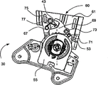
图3是座椅机构30的一个示例性实施方式的部分分解视图,所述座椅机构30包括闭锁机构40、倾躺机构50、座垫框架固定支架51和锁止机构60。闭锁机构40包括致动器31、弹簧32、驱动器33、闭锁杆35、闭锁销37、保持件支架39、枢转销柱41和闭锁线缆45(图5中示出)。锁止机构60包括线缆连接销柱43、靠背框架固定支架61、枢转轴衬63、以及侧板65、凸轮67(图4中示出)、棘爪69(图4中示出)、止挡销柱71(图4中示出)、棘爪枢轴73、凸轮枢轴75和凸轮复位弹簧77。倾躺机构50包括与座垫框架固定支架51刚性连接的基板55,以及与枢转轴衬63的一端刚性连接的齿板53。齿板53和基板55通过内部齿轮啮合而枢转地联接。座垫框架固定支架51可以与所述座垫框架刚性连接。枢转轴衬63可以具有与靠背框架固定支架61刚性连接的另一端。倾躺释放手柄21可以与致动器31刚性连接,所述致动器31枢转地与驱动器33相连接。释放手柄21和致动器31共用相同的转动轴线。FIG. 3 is a partially exploded view of an exemplary embodiment of a
驱动器33可以与同步管54键连接,所述驱动器33与容纳在倾躺机构50内以在转动时释放倾躺机构50的凸轮相连接。在图3和图4中公开的示例性实施方式中,同步管54与双侧型应用中使用的两个倾躺机构相连接,用于同时释放所述两个倾躺机构。一个备选实施方式可以具有一个倾躺机构,其中所述倾躺机构的凸轮与释放轴相连接,所述释放轴可以与驱动器33键连接。闭锁杆35绕其中心枢转地与枢转销柱41相连接,并且在一端包括线缆连接件,而在另一端包括槽,所述槽容纳闭锁销37并允许所述闭锁销37沿所述槽平移。枢转销柱41刚性地与保持件支架39相连接,所述保持件支架39与座垫框架固定支架51刚性连接。A
参照图4,示出了示例性的锁止机构60的侧视图,所述锁止机构60在其解锁时允许所述座椅靠背转动。所述锁止机构60包括枢转地与凸轮枢轴75相连接的凸轮67和枢转地与棘爪枢轴73相连接的棘爪69。凸轮67和棘爪69被容纳在侧板65(为清楚起见在图4中去除)与靠背框架固定支架61之间。棘爪69具有与齿板53的外齿相啮合的齿。锁止机构60可以包括止挡销柱71,所述止挡销柱71用于控制向后移动并用于消除与凸轮67的连接处的间隙,所述凸轮67通过凸轮复位弹簧77被触发转动。通过拉动锁止机构释放手柄23实现致动(在本实施方式中),这带动与线缆连接销柱43相连接的线缆,所述线缆连接销柱43继而使凸轮67沿逆时针方向绕凸轮枢轴75转动。凸轮67的逆时针转动引起棘爪69沿顺时针方向的相应转动。棘爪69的转动使棘爪69的齿与齿板53的齿脱离。与靠背框架固定支架61相连接的座椅靠背15然后可以相对于座椅坐垫17转动。在一个未示出的备选实施方式中,可以通过座椅靠背15的转动释放导轨系统,允许座椅系统13向前移动,从而允许用户使后座椅系统11的进入空间最大化。Referring to FIG. 4 , a side view of an
图5公开了位于乘坐者乘坐位置的座椅机构30的一个示例性实施方式。锁止机构60被解锁,触发座椅机构50的闭锁,这在所述座椅靠背展开时提供记忆。由于锁止机构60被解锁,因此闭锁机构40防止倾躺机构50被释放或解锁。FIG. 5 discloses an exemplary embodiment of a
在所述座椅的操作过程中,锁止机构释放手柄23的致动导致与线缆连接销柱43相连接的线缆发生相应的移动,从而使所述销柱43移动。闭锁线缆45具有与线缆连接销柱43相连接的一端和具有与闭锁杆35相连接的另一端。线缆连接销柱43的移动触发闭锁线缆45被带动,所述移动使闭锁杆35沿顺时针方向绕枢转销柱41转动,这进一步触发闭锁销37绕枢转销柱41转动。闭锁销37可以脱离致动器31的指状件所转动的圆弧而转动,从而致动器31的转动可以使得所述指状件在闭锁销37的下方转动而不接触所述闭锁销37。于是倾躺释放手柄21可以在不释放倾躺机构50的情况下转动。于是座椅靠背15可以被转动到其向前位置以增大进入空间,然后展开回复到锁止机构释放手柄23致动之前座椅靠背15的特定的舒适位置。During operation of the seat, actuation of the locking mechanism release handle 23 causes a corresponding movement of the cable connected to the
一个备选实施方式可以包括弹簧或类似装置,从而通过触发致动器31和倾躺释放手柄21的逆时针转动而使致动器31回复到其初始位置或锁定位置,这还允许闭锁销37更容易回复到其初始位置。另一个备选实施方式可以包括弹簧或其它适当的装置以使闭锁杆35回复到其初始位置,由此闭锁销37找到其初始位置。An alternative embodiment may include a spring or similar device whereby the
图6公开了位于乘坐者乘坐位置的座椅机构30的一个示例性实施方式,其中锁止机构60锁定而倾躺机构50解锁,从而为用户提供座椅靠背15的舒适度调节。倾躺释放手柄21的转动使致动器31沿顺时针方向转动,触发致动器31的指状件与闭锁销37接触。致动器31的进一步转动驱动闭锁销37与驱动器33的指状件接触。致动器31的继续转动和驱动器33随之的转动可以释放倾躺机构50以允许用户相对于所述座椅坐垫转动所述座椅靠背以提供特定的舒适乘坐位置。FIG. 6 discloses an exemplary embodiment of the
参照图7,一个示例性实施方式示出了位于乘坐者乘坐位置的座椅机构30,其中倾躺机构50和锁止机构60都被锁定。图中示出了致动器31和闭锁杆35的初始位置。Referring to FIG. 7 , an exemplary embodiment shows the
参照图8,示出了座椅机构30的一个示例性实施方式,所述座椅机构30与容纳在座椅系统13内的座椅结构相连接。座椅机构30采用双侧型结构被示出,所述双侧型结构带有如图7所示的左侧和对称地相对设置的右侧。一个备选实施方式可以采用单侧型结构,所述单侧型结构在一侧带有一个座椅机构30而在另一侧带有“自由枢轴”。一个示例性实施方式具有一对与所述座垫框架相连接的导轨,以提供座椅的向前和向后的舒适度调节,并且还在锁止机构释放手柄被致动时为座椅系统13提供进入空间。Referring to FIG. 8 , an exemplary embodiment of a
应该注意的是,说明书中提到的“前”、“后”、“顶”和“底”仅用于确认如附图中那样定位的各个元件,其中“前”和“后”相对于装置所设置的周围环境。It should be noted that references to "front", "rear", "top" and "bottom" in the specification are only used to identify the respective elements positioned as in the drawings, where "front" and "rear" are relative to the device The surrounding environment is set.
出于公开的目的,术语“联接”表示两个部件彼此直接或间接的接合。这种接合可以是本质上固定的或可移动的。这种接合可以通过使两个部件或使两个部件与任意附加的中间件彼此整体地形成为单独的整体而实现,或者通过使两个部件或使两个部件与任意附加的中间件彼此连接而实现。这种接合可以是本质上永久的或者本质上可去除或可释放的。For the purposes of this disclosure, the term "coupled" means the engagement of two components with each other, either directly or indirectly. Such engagement may be fixed or movable in nature. Such joining may be achieved by forming the two parts, or the two parts and any additional intermediate parts, integrally with each other as a single unit, or by connecting the two parts, or the two parts and any additional intermediate parts, to each other. accomplish. Such engagement may be permanent in nature or removable or releasable in nature.
重要的是,应当注意,在各种示例性实施方式中示出的交通工具座椅系统的结构和布置仅仅是示例性的。尽管只有几个实施方式在本公开内容中得到详细描述,但是阅读本公开内容的本领域技术人员将容易地认识到,在实质上没有脱离权利要求书所述主题的新颖性教导和优点的情况下,可以作出许多修改(例如,在各个元件的大小、尺寸、结构、形状和比例、参数值、安装布置、材料的使用、颜色、定位等方面的变化)。例如,示出为整体地形成的元件可以由多个部分或元件构成,元件的位置可以颠倒或作出其它变化,以及各个元件的特性或数量,或者位置可以改变或变化。任何过程或方法步骤的顺序或次序可以根据备选的实施方式变化或重新排序。在不脱离本发明实施方式的范围的情况下,还可在各个示例性实施方式的设计、操作条件和布置上作出其它的替换、修改、改变和省略。It is important to note that the structure and arrangement of the vehicle seating system shown in the various exemplary embodiments is exemplary only. Although only a few implementations have been described in detail in this disclosure, those skilled in the art who read this disclosure will readily appreciate that, without materially departing from the novel teachings and advantages of the subject matter described in the claims, Many modifications (for example, changes in size, dimensions, structure, shape and proportions of individual elements, parameter values, mounting arrangements, use of materials, colors, positioning, etc.) may be made. For example, elements shown as integrally formed may be constructed of multiple parts or elements, the position of elements may be reversed or otherwise varied, and the nature or number of individual elements, or the position, may be altered or varied. The order or sequence of any process or method steps may be varied or re-sequenced according to alternative implementations. Other substitutions, modifications, changes and omissions may also be made in the design, operating conditions and arrangement of the various exemplary embodiments without departing from the scope of the embodiments of the invention.
2007年1月24日提交的美国优先权申请60/897,131,包括说明书、附图、权利要求书和摘要都通过引用其全部内容结合于本申请中。
Claims (11)
Applications Claiming Priority (3)
| Application Number | Priority Date | Filing Date | Title |
|---|---|---|---|
| US89713107P | 2007-01-24 | 2007-01-24 | |
| US60/897,131 | 2007-01-24 | ||
| PCT/US2008/000879 WO2008091638A1 (en) | 2007-01-24 | 2008-01-24 | Vehicle seat |
Publications (2)
| Publication Number | Publication Date |
|---|---|
| CN101636294A CN101636294A (en) | 2010-01-27 |
| CN101636294B true CN101636294B (en) | 2014-05-28 |
Family
ID=39478352
Family Applications (1)
| Application Number | Title | Priority Date | Filing Date |
|---|---|---|---|
| CN200880008646.7A Expired - Fee Related CN101636294B (en) | 2007-01-24 | 2008-01-24 | vehicle seat |
Country Status (6)
| Country | Link |
|---|---|
| US (1) | US8491054B2 (en) |
| EP (1) | EP2109553B1 (en) |
| JP (1) | JP5558110B2 (en) |
| CN (1) | CN101636294B (en) |
| PL (1) | PL2109553T3 (en) |
| WO (1) | WO2008091638A1 (en) |
Families Citing this family (25)
| Publication number | Priority date | Publication date | Assignee | Title |
|---|---|---|---|---|
| DE102010045738B4 (en) * | 2010-09-03 | 2023-07-06 | Keiper Seating Mechanisms Co., Ltd. | Vehicle seat with a memory device |
| JP5591664B2 (en) * | 2010-11-29 | 2014-09-17 | トヨタ紡織株式会社 | Vehicle seat |
| FR2975052B1 (en) * | 2011-05-11 | 2014-02-07 | Faurecia Sieges Automobile | JOINT ASSEMBLY FOR VEHICLE SEAT AND VEHICLE SEAT COMPRISING THE JOINT ASSEMBLY |
| DE102011054608A1 (en) * | 2011-10-19 | 2013-04-25 | Brose Fahrzeugteile Gmbh & Co. Kommanditgesellschaft, Coburg | Seat with welded cross shaft |
| US20130270884A1 (en) * | 2012-04-11 | 2013-10-17 | Fisher & Company, Incorporated | Recliner mechanism with dump feature |
| DE102012015294B4 (en) * | 2012-07-31 | 2015-02-12 | Johnson Controls Gmbh | Adjustable vehicle seat |
| DE102013221925B3 (en) | 2013-08-27 | 2014-09-11 | Johnson Controls Components Gmbh & Co. Kg | Fitting with a Vorschwenkmechanismus and an easy-entry latch, easy-entry latch for such a fitting and vehicle seat with such a fitting |
| DE102014200753A1 (en) * | 2014-01-17 | 2015-08-06 | Lear Corporation | layout |
| DE102014213166B4 (en) * | 2014-07-07 | 2021-07-29 | Brose Fahrzeugteile SE & Co. Kommanditgesellschaft, Coburg | Vehicle seat with locking device and additional control device |
| US10220729B2 (en) | 2015-09-24 | 2019-03-05 | Faurecia Automotive Seating, Llc | Seat position-sensing system |
| CN109070767B (en) | 2016-04-11 | 2021-11-05 | 佛吉亚汽车座椅有限责任公司 | Recliner for vehicle seat |
| US10351020B2 (en) | 2016-09-29 | 2019-07-16 | Faurecia Automotive Seating, Llc | Recliner for a vehicle seat |
| US10414296B2 (en) | 2016-12-12 | 2019-09-17 | Faurecia Automotive Seating, Llc | Recliner for a vehicle seat |
| US10611273B2 (en) | 2017-10-09 | 2020-04-07 | Faurecia Automotive Seating, Llc | Recliner system for a vehicle seat |
| US10864830B2 (en) | 2018-04-25 | 2020-12-15 | Fisher & Company, Incorporated | Recliner mechanism having welded encapsulating ring |
| US11124093B2 (en) | 2018-08-08 | 2021-09-21 | Fisher & Company, Incorporated | Recliner mechanism for seat assembly and method of manufacturing |
| US11260777B2 (en) | 2018-08-29 | 2022-03-01 | Fisher & Company, Incorporated | Recliner heart for seat recliner assembly |
| US11364577B2 (en) | 2019-02-11 | 2022-06-21 | Fisher & Company, Incorporated | Recliner mechanism for seat assembly and method of manufacturing |
| US11845367B2 (en) | 2019-04-18 | 2023-12-19 | Fisher & Company, Incorporated | Recliner heart having lubricant member |
| US11052797B2 (en) | 2019-08-09 | 2021-07-06 | Fisher & Company, Incorporated | Recliner heart for seat assembly |
| US11192473B2 (en) | 2019-08-30 | 2021-12-07 | Fisher & Company, Incorporated | Release handle for recliner mechanism of vehicle seat |
| US11607976B2 (en) | 2020-03-06 | 2023-03-21 | Fisher & Company, Incorporated | Recliner mechanism having bracket |
| US11766957B2 (en) | 2021-02-16 | 2023-09-26 | Fisher & Company, Incorporated | Release mechanism for seat recliner assembly |
| US11897372B2 (en) | 2021-05-06 | 2024-02-13 | Fisher & Company, Incorporated | Recliner heart having biasing members |
| US11850975B2 (en) | 2021-06-11 | 2023-12-26 | Fisher & Company, Incorporated | Vehicle seat recliner mechanism with welded spring |
Citations (3)
| Publication number | Priority date | Publication date | Assignee | Title |
|---|---|---|---|---|
| CN2258833Y (en) * | 1996-02-28 | 1997-08-06 | 重庆明华汽车零件有限公司 | Multifunctional automotive seat back slope adjuster |
| US5788330A (en) * | 1997-03-27 | 1998-08-04 | Fisher Dynamics Corporation | Seat hinge mechanism with easy entry memory feature |
| DE19960878A1 (en) * | 1999-12-17 | 2001-07-05 | Keiper Gmbh & Co | Locking fitting for a vehicle seat, in particular for a motor vehicle seat |
Family Cites Families (10)
| Publication number | Priority date | Publication date | Assignee | Title |
|---|---|---|---|---|
| JPS5840913Y2 (en) * | 1977-10-28 | 1983-09-14 | 富士重工業株式会社 | Automobile seat backrest tilt angle storage device |
| FR2766138B1 (en) * | 1997-07-17 | 1999-10-01 | Faure Bertrand Equipements Sa | ARTICULATION MECHANISM FOR VEHICLE SEAT, AND VEHICLE SEAT EQUIPPED WITH SUCH A MECHANISM |
| US6848745B1 (en) * | 1999-11-05 | 2005-02-01 | Chuo Hatsujo Kabushiki Kaisha | Seat for vehicle |
| JP2001169846A (en) | 1999-12-20 | 2001-06-26 | Fuji Kiko Co Ltd | Seat reclining device with table mechanism |
| FR2822419B1 (en) * | 2000-12-29 | 2003-07-04 | Faurecia Sieges Automobile | VEHICLE SEAT HAVING A JOINT MECHANISM |
| JP4164045B2 (en) * | 2004-04-30 | 2008-10-08 | シロキ工業株式会社 | Seat reclining device |
| JP4527498B2 (en) | 2004-11-01 | 2010-08-18 | シロキ工業株式会社 | Sheet |
| JP4104601B2 (en) * | 2005-02-14 | 2008-06-18 | トヨタ車体株式会社 | Vehicle seat |
| DE202005012733U1 (en) * | 2005-08-12 | 2006-12-28 | Brose Fahrzeugteile Gmbh & Co. Kommanditgesellschaft, Coburg | Lehnenklappung |
| US7556315B2 (en) * | 2006-03-31 | 2009-07-07 | Lear Corporation | Latch actuator system |
-
2008
- 2008-01-24 JP JP2009547282A patent/JP5558110B2/en not_active Expired - Fee Related
- 2008-01-24 US US12/524,223 patent/US8491054B2/en not_active Expired - Fee Related
- 2008-01-24 PL PL08724732T patent/PL2109553T3/en unknown
- 2008-01-24 WO PCT/US2008/000879 patent/WO2008091638A1/en not_active Ceased
- 2008-01-24 CN CN200880008646.7A patent/CN101636294B/en not_active Expired - Fee Related
- 2008-01-24 EP EP08724732.6A patent/EP2109553B1/en not_active Not-in-force
Patent Citations (3)
| Publication number | Priority date | Publication date | Assignee | Title |
|---|---|---|---|---|
| CN2258833Y (en) * | 1996-02-28 | 1997-08-06 | 重庆明华汽车零件有限公司 | Multifunctional automotive seat back slope adjuster |
| US5788330A (en) * | 1997-03-27 | 1998-08-04 | Fisher Dynamics Corporation | Seat hinge mechanism with easy entry memory feature |
| DE19960878A1 (en) * | 1999-12-17 | 2001-07-05 | Keiper Gmbh & Co | Locking fitting for a vehicle seat, in particular for a motor vehicle seat |
Also Published As
| Publication number | Publication date |
|---|---|
| WO2008091638A1 (en) | 2008-07-31 |
| US20100231021A1 (en) | 2010-09-16 |
| EP2109553B1 (en) | 2013-11-27 |
| JP5558110B2 (en) | 2014-07-23 |
| JP2010516553A (en) | 2010-05-20 |
| PL2109553T3 (en) | 2014-04-30 |
| CN101636294A (en) | 2010-01-27 |
| EP2109553A1 (en) | 2009-10-21 |
| US8491054B2 (en) | 2013-07-23 |
Similar Documents
| Publication | Publication Date | Title |
|---|---|---|
| CN101636294B (en) | vehicle seat | |
| CN111319527B (en) | Vehicle seating system | |
| US5788330A (en) | Seat hinge mechanism with easy entry memory feature | |
| US5769493A (en) | Linear recliner with easy entry memory feature | |
| US5660440A (en) | Linear recliner with easy entry memory feature | |
| US6199953B1 (en) | Sector recliner with single position memory | |
| US7021716B2 (en) | Tip easy entry and fold flat recliner assembly | |
| JP2007509815A (en) | Vehicle seat system with entry / exit positions and loading floor positions | |
| WO2003084779A1 (en) | Fold-flat seat hinge assembly | |
| EP2321146A1 (en) | Tip slide stow seat | |
| CN107848445B (en) | Vehicle seat recliner device with recliner hard lock | |
| US20020180251A1 (en) | Dual-cam seat-hinge assembly | |
| CN204432435U (en) | Angle regulator for automobile chair is with sliding rail unlocking mechanism and automotive seat | |
| JPH11342773A (en) | Track of seat having fixing device driven by cam | |
| WO2020198116A2 (en) | Stow in floor seat assembly | |
| JPS6319225Y2 (en) | ||
| JP2000025498A (en) | Car seat | |
| JPH09207637A (en) | Vehicle seat storage structure | |
| US20250170926A1 (en) | Vehicle seat for one-touch switching to relaxation mode | |
| KR100512879B1 (en) | Reclining device of seat for vehicle | |
| KR100534257B1 (en) | Keeping Seat Holder for a Vehicle | |
| JPH0515238Y2 (en) | ||
| KR20230039200A (en) | Device for rotating headrest of seat for vehicle | |
| CN120534254A (en) | Flip-up headrests and vehicle seats | |
| WO2002081256A2 (en) | Manual fold-flat seat hinge assembly |
Legal Events
| Date | Code | Title | Description |
|---|---|---|---|
| C06 | Publication | ||
| PB01 | Publication | ||
| C10 | Entry into substantive examination | ||
| SE01 | Entry into force of request for substantive examination | ||
| C14 | Grant of patent or utility model | ||
| GR01 | Patent grant | ||
| CF01 | Termination of patent right due to non-payment of annual fee | ||
| CF01 | Termination of patent right due to non-payment of annual fee |
Granted publication date: 20140528 Termination date: 20190124 |