CN101636231A - Specimen container with physical fill line marking - Google Patents
Specimen container with physical fill line marking Download PDFInfo
- Publication number
- CN101636231A CN101636231A CN200780038958A CN200780038958A CN101636231A CN 101636231 A CN101636231 A CN 101636231A CN 200780038958 A CN200780038958 A CN 200780038958A CN 200780038958 A CN200780038958 A CN 200780038958A CN 101636231 A CN101636231 A CN 101636231A
- Authority
- CN
- China
- Prior art keywords
- fill
- volume
- side wall
- container
- sample
- Prior art date
- Legal status (The legal status is an assumption and is not a legal conclusion. Google has not performed a legal analysis and makes no representation as to the accuracy of the status listed.)
- Pending
Links
Images


Classifications
-
- B—PERFORMING OPERATIONS; TRANSPORTING
- B01—PHYSICAL OR CHEMICAL PROCESSES OR APPARATUS IN GENERAL
- B01L—CHEMICAL OR PHYSICAL LABORATORY APPARATUS FOR GENERAL USE
- B01L3/00—Containers or dishes for laboratory use, e.g. laboratory glassware; Droppers
- B01L3/50—Containers for the purpose of retaining a material to be analysed, e.g. test tubes
- B01L3/508—Rigid containers without fluid transport within
- B01L3/5082—Test tubes per se
-
- A—HUMAN NECESSITIES
- A61—MEDICAL OR VETERINARY SCIENCE; HYGIENE
- A61B—DIAGNOSIS; SURGERY; IDENTIFICATION
- A61B5/00—Measuring for diagnostic purposes; Identification of persons
- A61B5/14—Devices for taking samples of blood ; Measuring characteristics of blood in vivo, e.g. gas concentration within the blood, pH-value of blood
- A61B5/1405—Devices for taking blood samples
-
- A—HUMAN NECESSITIES
- A61—MEDICAL OR VETERINARY SCIENCE; HYGIENE
- A61B—DIAGNOSIS; SURGERY; IDENTIFICATION
- A61B5/00—Measuring for diagnostic purposes; Identification of persons
- A61B5/15—Devices for taking samples of blood
- A61B5/150007—Details
- A61B5/150015—Source of blood
- A61B5/15003—Source of blood for venous or arterial blood
-
- A—HUMAN NECESSITIES
- A61—MEDICAL OR VETERINARY SCIENCE; HYGIENE
- A61B—DIAGNOSIS; SURGERY; IDENTIFICATION
- A61B5/00—Measuring for diagnostic purposes; Identification of persons
- A61B5/15—Devices for taking samples of blood
- A61B5/150007—Details
- A61B5/150351—Caps, stoppers or lids for sealing or closing a blood collection vessel or container, e.g. a test-tube or syringe barrel
-
- A—HUMAN NECESSITIES
- A61—MEDICAL OR VETERINARY SCIENCE; HYGIENE
- A61B—DIAGNOSIS; SURGERY; IDENTIFICATION
- A61B5/00—Measuring for diagnostic purposes; Identification of persons
- A61B5/15—Devices for taking samples of blood
- A61B5/150007—Details
- A61B5/150755—Blood sample preparation for further analysis, e.g. by separating blood components or by mixing
-
- A—HUMAN NECESSITIES
- A61—MEDICAL OR VETERINARY SCIENCE; HYGIENE
- A61B—DIAGNOSIS; SURGERY; IDENTIFICATION
- A61B5/00—Measuring for diagnostic purposes; Identification of persons
- A61B5/15—Devices for taking samples of blood
- A61B5/153—Devices specially adapted for taking samples of venous or arterial blood, e.g. with syringes
- A61B5/154—Devices using pre-evacuated means
- A61B5/1545—Devices using pre-evacuated means comprising means for indicating vein or arterial entry
-
- B—PERFORMING OPERATIONS; TRANSPORTING
- B01—PHYSICAL OR CHEMICAL PROCESSES OR APPARATUS IN GENERAL
- B01L—CHEMICAL OR PHYSICAL LABORATORY APPARATUS FOR GENERAL USE
- B01L2200/00—Solutions for specific problems relating to chemical or physical laboratory apparatus
- B01L2200/12—Specific details about manufacturing devices
-
- B—PERFORMING OPERATIONS; TRANSPORTING
- B01—PHYSICAL OR CHEMICAL PROCESSES OR APPARATUS IN GENERAL
- B01L—CHEMICAL OR PHYSICAL LABORATORY APPARATUS FOR GENERAL USE
- B01L2300/00—Additional constructional details
- B01L2300/02—Identification, exchange or storage of information
-
- B—PERFORMING OPERATIONS; TRANSPORTING
- B01—PHYSICAL OR CHEMICAL PROCESSES OR APPARATUS IN GENERAL
- B01L—CHEMICAL OR PHYSICAL LABORATORY APPARATUS FOR GENERAL USE
- B01L2300/00—Additional constructional details
- B01L2300/04—Closures and closing means
- B01L2300/041—Connecting closures to device or container
- B01L2300/044—Connecting closures to device or container pierceable, e.g. films, membranes
-
- B—PERFORMING OPERATIONS; TRANSPORTING
- B01—PHYSICAL OR CHEMICAL PROCESSES OR APPARATUS IN GENERAL
- B01L—CHEMICAL OR PHYSICAL LABORATORY APPARATUS FOR GENERAL USE
- B01L2300/00—Additional constructional details
- B01L2300/08—Geometry, shape and general structure
- B01L2300/0848—Specific forms of parts of containers
- B01L2300/0854—Double walls
-
- Y—GENERAL TAGGING OF NEW TECHNOLOGICAL DEVELOPMENTS; GENERAL TAGGING OF CROSS-SECTIONAL TECHNOLOGIES SPANNING OVER SEVERAL SECTIONS OF THE IPC; TECHNICAL SUBJECTS COVERED BY FORMER USPC CROSS-REFERENCE ART COLLECTIONS [XRACs] AND DIGESTS
- Y10—TECHNICAL SUBJECTS COVERED BY FORMER USPC
- Y10T—TECHNICAL SUBJECTS COVERED BY FORMER US CLASSIFICATION
- Y10T29/00—Metal working
- Y10T29/49—Method of mechanical manufacture
- Y10T29/49826—Assembling or joining
- Y10T29/49879—Spaced wall tube or receptacle
-
- Y—GENERAL TAGGING OF NEW TECHNOLOGICAL DEVELOPMENTS; GENERAL TAGGING OF CROSS-SECTIONAL TECHNOLOGIES SPANNING OVER SEVERAL SECTIONS OF THE IPC; TECHNICAL SUBJECTS COVERED BY FORMER USPC CROSS-REFERENCE ART COLLECTIONS [XRACs] AND DIGESTS
- Y10—TECHNICAL SUBJECTS COVERED BY FORMER USPC
- Y10T—TECHNICAL SUBJECTS COVERED BY FORMER US CLASSIFICATION
- Y10T29/00—Metal working
- Y10T29/49—Method of mechanical manufacture
- Y10T29/4998—Combined manufacture including applying or shaping of fluent material
Landscapes
- Health & Medical Sciences (AREA)
- Life Sciences & Earth Sciences (AREA)
- Hematology (AREA)
- General Health & Medical Sciences (AREA)
- Molecular Biology (AREA)
- Physics & Mathematics (AREA)
- Engineering & Computer Science (AREA)
- Biomedical Technology (AREA)
- Heart & Thoracic Surgery (AREA)
- Medical Informatics (AREA)
- Biophysics (AREA)
- Surgery (AREA)
- Animal Behavior & Ethology (AREA)
- Pathology (AREA)
- Public Health (AREA)
- Veterinary Medicine (AREA)
- Chemical & Material Sciences (AREA)
- Analytical Chemistry (AREA)
- Clinical Laboratory Science (AREA)
- Chemical Kinetics & Catalysis (AREA)
- Vascular Medicine (AREA)
- Investigating Or Analysing Biological Materials (AREA)
- Sampling And Sample Adjustment (AREA)
Abstract
Description
[0001]本申请要求2006年9月8日提交的临时申请No.60/843,160的优先权。[0001] This application claims priority to Provisional Application No. 60/843,160, filed September 8, 2006.
发明背景Background of the invention
技术领域 technical field
[0002]本发明涉及一种生物试样容器,尤其涉及具有至少一个填注线标志的生物流体收集容器。[0002] The present invention relates to a biological sample container, and more particularly to a biological fluid collection container having at least one fill line marker.
背景技术 Background technique
[0003]生物试样容器在历史上已经用于收集样本,例如血液和其它身体流体,例如为了执行诊断试验的目的。在许多情况下,需要预定体积的样本执行特定试验,并且常常利用这样的容器方便例如用诸如血液收集管这样的流体收集容器收集精确的试验特定性样本体积。在一些这样的试样容器中,预测量的添加剂例如防腐剂或抗凝血剂被注入容器中以保存或准备试样。因此,重要的是在容器内收集的流体试样的量对应于容器内的添加剂的体积和/或预期试验体积。[0003] Biological sample containers have historically been used to collect samples, such as blood and other body fluids, for example for the purpose of performing diagnostic tests. In many cases, a predetermined volume of sample is required to perform a particular assay, and such containers are often utilized to facilitate the collection of precise assay-specific sample volumes, eg, with fluid collection containers such as blood collection tubes. In some of these sample containers, pre-measured additives such as preservatives or anticoagulants are injected into the container to preserve or prepare the sample. Therefore, it is important that the amount of fluid sample collected in the container corresponds to the volume of additive and/or the intended test volume in the container.
[0004]测量样本体积的传统方法包括在试样容器的外表面上在精确位置设置黏性标签。这允许医务人员通过将容器内的液体的量与标签上的标记或标签的上或下缘相对准,来测量样本体积。然而,该方法存在显著缺陷。需要复杂机器以正确地对准试样容器的外表上的标签。标签设置的误差会导致不精确的填注体积并且因此导致不精确的相应试验结果,尤其在试样与添加剂的比率将被正确控制和保持的情况下。具有未对准标签的试样容器通常作为有缺陷产品被丢弃并且导致成本增加。另外,附着到试样容器的外表的标签会通过例行程序被损坏,并且可以容易地由另外的患者或试样收集标记覆盖。[0004] Traditional methods of measuring sample volume include placing adhesive labels at precise locations on the outer surface of the sample container. This allows medical personnel to measure the sample volume by aligning the amount of liquid in the container with the marking on the label or the upper or lower edge of the label. However, this approach has significant drawbacks. Complex machinery is required to correctly align the labels on the exterior of the sample container. Errors in label setting can lead to inaccurate fill volumes and thus inaccurate corresponding test results, especially if the ratio of sample to additive is to be properly controlled and maintained. Sample containers with misaligned labels are often discarded as defective products and result in increased costs. Additionally, labels attached to the exterior of the sample container can be damaged through routine procedures and can easily be covered by additional patient or sample collection labels.
发明内容 Contents of the invention
[0005]因此,需要一种改进的试样容器,其允许医务人员在视觉上获得样本的精确体积和/或样本与容器中存在的试剂的预期组合体积。[0005] Accordingly, there is a need for an improved sample container that allows medical personnel to visually obtain the precise volume of the sample and/or the expected combined volume of the sample and reagents present in the container.
[0006]根据本发明的一个方面,一种样本收集容器组件包括第一开口、第一闭合底部以及在第一开口与第一闭合底部之间沿圆周延伸的第一侧壁。该第一管状元件能够在其中接纳样本试样。所述容器组件进一步包括第二管状元件,所述第二管状元件具有第二开口、第二闭合底部以及在第二开口与第二闭合底部之间沿圆周延伸的第二侧壁。第一管状元件被布置在第二管状元件内。填注线标志被定位在第一侧壁和第二侧壁中的一个上。该填注线标志至少对应于所述收集容器的最小预期填注体积。[0006] According to one aspect of the present invention, a sample collection container assembly includes a first opening, a first closed bottom, and a first side wall extending circumferentially between the first opening and the first closed bottom. The first tubular element is capable of receiving a sample sample therein. The container assembly further includes a second tubular member having a second opening, a second closed bottom, and a second sidewall extending circumferentially between the second opening and the second closed bottom. The first tubular element is arranged within the second tubular element. A fill line marker is positioned on one of the first sidewall and the second sidewall. The filling line marking corresponds at least to the minimum expected filling volume of the collection container.
[0007]根据本发明的另一方面,一种生物样本收集容器组件包括第一管状元件,所述第一管状元件具有第一开口、第一闭合底部以及在第一开口与第一闭合底部之间沿圆周延伸的第一侧壁。该第一管状元件能够在其中接纳样本试样。所述容器组件进一步包括第二管状元件,所述第二管状元件具有第二开口、第二闭合底部以及在第二开口与第二闭合底部之间沿圆周延伸的第二侧壁。该第二侧壁具有内表面和外表面以及与第二侧壁的内表面一体化的填注线标志。所述填注线标志至少对应于所述收集容器的最小预期填注体积,并且第一管状元件被布置在第二管状元件内。[0007] According to another aspect of the present invention, a biological sample collection container assembly includes a first tubular element, the first tubular element has a first opening, a first closed bottom, and between the first opening and the first closed bottom and a first side wall extending circumferentially. The first tubular element is capable of receiving a sample sample therein. The container assembly further includes a second tubular member having a second opening, a second closed bottom, and a second sidewall extending circumferentially between the second opening and the second closed bottom. The second side wall has an inner surface and an outer surface and a fill line marking integral with the inner surface of the second side wall. The fill line marking corresponds at least to a minimum expected fill volume of the collection container, and the first tubular element is arranged within the second tubular element.
[0008]根据本发明的另一方面,一种样本收集容器组件包括管状元件,所述管状元件具有开口、闭合底部以及在所述开口与所述闭合底部之间沿圆周延伸的侧壁。所述管状元件能够在其中接纳样本试样。填注线标志被定位在所述侧壁的内表面上。所述填注线标志至少对应于所述收集容器的最小预期填注体积。[0008] According to another aspect of the invention, a sample collection container assembly includes a tubular member having an opening, a closed bottom, and a sidewall extending circumferentially between the opening and the closed bottom. The tubular element is capable of receiving a sample sample therein. A fill line marker is positioned on the inner surface of the side wall. The filling line marking corresponds at least to the minimum expected filling volume of the collecting container.
[0009]根据本发明的又一方面,一种制造样本收集容器的方法包括模制第一管状元件,所述第一管状元件具有第一开口、第一闭合底部以及在第一开口与第一闭合底部之间沿圆周延伸的第一侧壁。第一管状元件具有用于在其中接纳样本试样的预定体积。所述方法进一步包括模制第二管状元件,所述第二管状元件具有第二开口、第二闭合底部以及在第二开口与第二闭合底部之间沿圆周延伸的第二侧壁;在第一侧壁和第二侧壁中的一个上设置填注线标志,其中该填注线标志至少对应于所述收集容器的最小预期填注体积;以及将第一管状元件定位在第二管状元件内。[0009] According to yet another aspect of the present invention, a method of manufacturing a sample collection container includes molding a first tubular member having a first opening, a first closed bottom, and a joint between the first opening and the first A first side wall extending circumferentially between the closed bases. The first tubular element has a predetermined volume for receiving a sample sample therein. The method further includes molding a second tubular member having a second opening, a second closed bottom, and a second sidewall extending circumferentially between the second opening and the second closed bottom; at providing a fill line marker on one of the side wall and the second side wall, wherein the fill line marker corresponds to at least the minimum expected fill volume of the collection container; and positioning the first tubular element on the second tubular element Inside.
[0010]根据本发明的另一方面,一种制造样本收集容器的方法包括模制管状元件,所述管状元件具有第一端、第二端以及在第一端与第二端之间沿圆周延伸的侧壁。所述管状元件具有用于在其中接纳样本试样的预定体积。第二端可以是管的闭合底部或者它可以是敞开端以形成双端敞口管。在该实施方式中,所述两个开口可以由独立封闭件闭合。所述方法进一步包括在所述侧壁的内表面上设置填注线标志。该填注线标志至少对应于所述收集容器的最小预期填注体积。[0010] According to another aspect of the present invention, a method of manufacturing a sample collection container includes molding a tubular member having a first end, a second end, and a circumferential edge between the first end and the second end. Extended side walls. The tubular element has a predetermined volume for receiving a sample sample therein. The second end may be the closed bottom of the tube or it may be an open end to form a double ended open tube. In this embodiment, the two openings can be closed by separate closures. The method further includes providing a fill line marker on an inner surface of the sidewall. The filling line marking corresponds at least to the minimum expected filling volume of the collection container.
[0011]根据本发明的进一步方面,所述填注线标志可以包括单线,所述单线围绕第一侧壁和第二侧壁中的一个的一部分至少局部地沿圆周延伸,其中该单线具有第一预定宽度,所述第一预定宽度对应于所述收集容器的预期填注体积的最小体积。备选地,根据本发明的另一方面,所述填注线标志可以包括上线和下线,所述上线和下线围绕第一侧壁和第二侧壁中的一个的一部分至少局部地沿圆周延伸并且彼此间隔预定距离,其中所述上线限定最大预期填注体积并且所述下线限定最小预期填注体积,并且其中所述上线和下线之间的间隔限定所述收集容器的预期填注体积的体积范围。根据本发明的又一方面,所述填注线标志也可以包括单线,所述单线围绕第一侧壁和第二侧壁中的一个的一部分至少局部地沿圆周延伸,其中该单线具有由上边界和下边界限定的第二预定宽度。所述上边界限定最大预期填注体积,所述下边界限定最小预期填注体积,并且第二预定宽度限定所述收集容器的预期填注体积的体积范围。[0011] According to a further aspect of the present invention, the fill line marker may comprise a single line extending at least partially circumferentially around a portion of one of the first side wall and the second side wall, wherein the single line has a first A predetermined width, the first predetermined width corresponding to the minimum volume of the expected fill volume of the collection container. Alternatively, according to another aspect of the present invention, the fill line marker may include an upper line and a lower line at least partially around a portion of one of the first side wall and the second side wall. Circumferentially extending and spaced a predetermined distance from each other, wherein the upper line defines a maximum expected fill volume and the lower line defines a minimum expected fill volume, and wherein the spacing between the upper and lower lines defines an expected fill volume of the collection container. Note the volume range of the volume. According to yet another aspect of the present invention, the fill line marker may also comprise a single line extending at least partially circumferentially around a portion of one of the first side wall and the second side wall, wherein the single line has a A second predetermined width defined by the border and the lower border. The upper boundary defines a maximum expected fill volume, the lower boundary defines a minimum expected fill volume, and the second predetermined width defines a volume range of the collection container's expected fill volume.
[0012]所述填注线标志可以包括应用于第一或第二管状元件的第一或第二侧壁的视觉标记。备选地,所述填注线标志可以与形成管状元件的模制材料形成一体,从而在第一或第二管状元件的第一或第二侧壁上形成纹理化表面。该纹理化表面能够散射光和/或在所述容器上形成不透明表面,并且可以在注射模制过程期间形成于所述管中的一个上。[0012] The fill line marker may comprise a visual marking applied to the first or second sidewall of the first or second tubular member. Alternatively, the fill line markings may be integral with the molding material forming the tubular element so as to form a textured surface on the first or second side wall of the first or second tubular element. The textured surface is capable of scattering light and/or forming an opaque surface on the container, and may be formed on one of the tubes during the injection molding process.
[0013]结合附图,从优选实施方式的以下描述将理解进一步的细节和优点,在所有附图中类似的参考数字表示类似的元件。[0013] Further details and advantages will be appreciated from the following description of preferred embodiments, taken in conjunction with the accompanying drawings, wherein like reference numerals refer to like elements throughout.
附图说明 Description of drawings
[0014]图1是根据本发明的第一方面的具有单宽带填注线标志的容器的立体图;[0014] FIG. 1 is a perspective view of a container having a single broadband fill line marking according to a first aspect of the invention;
[0015]图2是根据本发明的第二方面的具有一对填注线标志的容器的立体图;[0015] FIG. 2 is a perspective view of a container having a pair of fill line markings according to a second aspect of the invention;
[0016]图3是根据本发明的第三方面的具有显示最小预期填注体积的单填注线标志的容器的立体图;[0016] FIG. 3 is a perspective view of a container having a single fill line marking showing the minimum expected fill volume according to a third aspect of the invention;
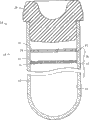
[0017]图4根据本发明第一实施方式显示了形成于第二管的内表面上的图1的宽带填注线的横截面图;[0017] FIG. 4 shows a cross-sectional view of the broadband fill line of FIG. 1 formed on the inner surface of a second pipe according to a first embodiment of the invention;
[0018]图5根据本发明的第一实施方式显示了形成于第二管的内表面上的图2的一对填注线标志的横截面图;[0018] FIG. 5 shows a cross-sectional view of the pair of fill line markers of FIG. 2 formed on the inner surface of a second pipe according to a first embodiment of the invention;
[0019]图6根据本发明的第一实施方式显示了形成于第二管的内表面上的图3的细线填注线的横截面图;[0019] FIG. 6 shows a cross-sectional view of the fine line fill line of FIG. 3 formed on the inner surface of a second tube according to a first embodiment of the invention;
[0020]图7根据本发明第二实施方式显示了形成于第一管的内表面上的图1的宽带填注线的横截面图;[0020] FIG. 7 shows a cross-sectional view of the broadband fill line of FIG. 1 formed on the inner surface of a first pipe according to a second embodiment of the invention;
[0021]图8根据本发明的第二实施方式显示了形成于第一管的内表面上的图2的一对填注线标志的横截面图;[0021] FIG. 8 shows a cross-sectional view of the pair of fill line markers of FIG. 2 formed on the inner surface of the first pipe according to a second embodiment of the invention;
[0022]图9根据本发明的第二实施方式显示了形成于第一管的内表面上的图3的细线填注线的横截面图;[0022] FIG. 9 shows a cross-sectional view of the fine line fill line of FIG. 3 formed on the inner surface of the first tube according to a second embodiment of the invention;
[0023]图10根据本发明第三实施方式显示了形成于第一管的外表面上的图1的宽带填注线的横截面图;[0023] FIG. 10 shows a cross-sectional view of the broadband fill line of FIG. 1 formed on the outer surface of a first pipe according to a third embodiment of the invention;
[0024]图11根据本发明的第三实施方式显示了形成于第一管的外表面上的图2的一对填注线标志的横截面图;[0024] FIG. 11 shows a cross-sectional view of the pair of fill line markers of FIG. 2 formed on the outer surface of the first pipe according to a third embodiment of the invention;
[0025]图12根据本发明的第三实施方式显示了形成于第一管的外表面上的图3的细线填注线的横截面图;[0025] FIG. 12 shows a cross-sectional view of the fine line fill line of FIG. 3 formed on the outer surface of the first tube according to a third embodiment of the invention;
[0026]图13根据本发明第四实施方式显示了形成于单管的内表面上的图1的宽带填注线的横截面图;[0026] FIG. 13 shows a cross-sectional view of the broadband fill line of FIG. 1 formed on the inner surface of a single pipe according to a fourth embodiment of the invention;
[0027]图14根据本发明的第四实施方式显示了形成于单管的内表面上的图2的一对填注线标志的横截面图;[0027] FIG. 14 shows a cross-sectional view of a pair of fill line markers of FIG. 2 formed on the inner surface of a single pipe according to a fourth embodiment of the invention;
[0028]图15根据本发明的第四实施方式显示了形成于单管的内表面上的图3的细线填注线的横截面图;并且[0028] FIG. 15 shows a cross-sectional view of the fine line fill line of FIG. 3 formed on the inner surface of a single tube according to a fourth embodiment of the invention; and
[0029]图16根据本发明的另一实施方式显示了双端敞口管的立体图。[0029] FIG. 16 shows a perspective view of a double-ended open tube according to another embodiment of the present invention.
具体实施方式 Detailed ways
[0030]为了下文的描述起见,空间或方向术语与本发明的关系就如同它在附图中被定向。然而,应当理解本发明可以采用各种备选变化,除非相反地清楚规定。也应当理解在附图中示出和在以下说明书中描述的特定部件仅仅是本发明的例示性实施方式。因此,涉及这里公开的实施方式的特定尺度和其它物理特征不应当被视为是限制性的。[0030] For purposes of the following description, spatial or directional terms relate to the invention as it is oriented in the drawings. However, it should be understood that the invention may employ various alternative changes unless expressly specified to the contrary. It should also be understood that certain components shown in the drawings and described in the following specification are merely exemplary embodiments of the invention. Accordingly, specific dimensions and other physical characteristics relating to the embodiments disclosed herein should not be considered as limiting.
[0031]现在参看图1-3,所述图显示了总体被标示为10的收集容器的立体图,所述收集容器例如是生物流体样本收集容器。容器10包括管状元件,该管状元件具有开口12,闭合底部14,和在开口12与闭合底部14之间沿圆周延伸以形成管的侧壁16。容器10具有能够在其中接纳样本试样的预定内部体积。总体被标示为18的填注线标志被定位在侧壁16上。该填注线标志18至少对应于收集容器10的最小预期填注体积。尽管在这里的某些实施方式中以生物流体收集容器、例如血液收集管、尤其是真空血液收集管的形式,来对容器10加以描述,可以预见本发明的实施方式可以涉及任何生物试样容器。[0031] Referring now to FIGS. 1-3, there are shown perspective views of a collection container, generally designated 10, such as a biological fluid sample collection container. The
[0032]图1-3的容器10具有内表面20和外表面22。血液、尿和/或其它身体流体可以被收集在容器组件10内以用于随后的试验程序。容器10例如可以包括玻璃或聚合物成分,例如聚丙烯、尼龙、聚苯乙烯、环烯烃共聚物、聚对苯二甲酸乙二醇酯和/或聚乙烯。容器可以具有任何合适的长度L和与它的预期用途一致的任何合适的宽度W(或直径)。在一个实施方式中,容器10代表具有从大约1到大约7毫升(ml)、例如大约2.7ml的预期填注容量的收集管。在另一实施方式中,容器可以具有大约1.8ml的预期填注容量。[0032] The
[0033]容器10包括与侧壁6形成一体的填注线标志18,所述填注线标志对应于期望或预期样本填注容量。在一些实施方式中,预期样本填注容量可以仅仅包括样本。在其它实施方式中,预期样本填注容量可以包括样本和添加剂。预期填注体积可以被定义为仅仅进入容器的生物流体例如血液的体积或生物流体加上添加剂例如试剂的体积。在其它情况下,预期填注体积可以包括生物流体加上分离器(凝胶的或机械的)的体积和/或生物流体加上分离器和添加剂的体积。[0033] The
[0034]填注线标志18可以至少指示期望的最小预期填注体积并且可以对应于包含在容器组件10内的液体样本的弯月面。填注线标志18可以围绕容器10的侧壁的圆周连续地被布置,或者备选地,填注线标志18可以围绕侧壁16的一部分至少局部地沿圆周延伸。[0034] Fill line marking 18 may indicate at least a desired minimum expected fill volume and may correspond to a meniscus of a liquid sample contained within
[0035]在这里公开的实施方式中,填注线标志18为容器提供关于当容器10被垂直定位,在该情况下直立,即处于闭合位置时容器10的预期填注体积的指示。以该方式,填注线体积标志18提供关于容器10内的试样量是否是容器10的期望或预期填注体积的确认。这样的填注线标志18特别有助于试样收集容器,例如用于确定容器内的试样量是否匹配特定收集容器的特定预定抽吸体积。在其它实施方式中,填注线体积标志18提供关于当容器在非垂直位置被定位时容器的期望或预期填注体积的指示。例如,血液收集容器典型地包括在它的内部的负压或真空。能被穿刺的封闭件24用于封盖容器10并且保持其中的该负压。在使用中,血液收集针头进入患者的血管,并且被设置成与血液收集容器10的内部流体连通。容器10内的负压通过针头从血管将血液试样抽吸到收集容器的内部。最后,收集容器10内的压力与血压平衡,在这时不会有另外的试样被抽吸到收集容器中。因此,收集容器10的内部可以包括负压以在收集容器10内提供足够的真空,从而保证基于该真空而使预定体积的血液被抽吸到容器中。[0035] In the embodiments disclosed herein, the
[0036]进一步地,试样容器10可以在其中包含与将对试样执行的期望试验关联的特定试剂。试剂的一个例子包括柠檬酸盐。试剂的量可以特别地适合于容器的试样的特定预期填注体积。如果抽吸到容器10中的试样量不匹配样本试样和试剂的特定预期填注体积,试剂可能与试样不适当地反应,由此可能提供不精确的试验结果。填注线标志18提供一种机构以便于保证用于与容器中的试剂反应的试样的适当体积被收集在容器10内。例如,真空收集容器的长期储存会导致其中的真空度降低,由此减小容器10的抽吸体积。而且,在初始血液抽吸期间,针头中会包括空气,该空气被转移到用于抽吸的第一收集容器中。该空气可以减小容器10的总填注体积,使得被抽吸到容器中的血液量不足以用于包含在其中的试剂。通过设置填注线标志18,在血液抽吸之后使用者立即可以确认预期用于该容器10的适当试样量实际上已被收集到容器10内。而且,通过提供与容器自身一体化的填注线标志18,预期填注体积有效地被设置并且直接与容器结合,而不会存在用于识别预定或预期填注体积的独立标签对不准的机会。[0036] Further, the
[0037]更进一步地,填注线标志18可以为实验室技术人员提供关于包含在容器10内的体积是否是预期填注体积的确认,特别是对于特定类型的容器。该指示也可以有助于确认试样是否已从容器10被取出供分析。[0037] Still further, the
[0038]在一个实施方式中,填注线标志18代表侧壁16的一部分,其具有不同轮廓、表面、纹理等,并且因此适于与限定容器10的侧壁16的其余部分不同地散射通过侧壁16的光。[0038] In one embodiment, the
[0039]填注线标志18可以由各种技术形成。例如,填注线标志18可以包括脊部,所述脊部从组件的侧壁16升高,围绕容器10沿圆周延伸。脊部可以从侧壁16的表面延伸。在另一实施方式中,脊部可以凹陷到侧壁16中以形成凹槽。这样的脊部的高度和/或这样的凹槽的深度可以是任何预期量,只要脊部和/或凹槽的尺度为人眼提供唯一识别物(或一些其它指示),所述识别物区分脊部和/或凹槽与侧壁16以代表填注线标志。在进一步的实施方式中,填注线标志18可以包括与侧壁16的颜色不同的色带。在这样的实施方式中,侧壁16可以是大体透明材料,独立色带被喷涂、印刷或以另外方式施加到侧壁16的内表面或外表面以形成填注线标志18。[0039]
[0040]优选地,可以在用于形成容器10的注射模制过程期间形成填注线标志18。在这样的过程中,模芯元件与模腔配合并且塑料材料被注射到芯和腔之间的腔中以形成管状元件。通过提供至少部分围绕芯元件的周边的糙化或纹理化表面形成填注线标志18。因此,在模制过程期间,该糙化表面被施加到容器10的侧壁16的内表面。与腔元件相反,在注射模制设备的芯元件上提供糙化或纹理化表面提供的优点在于更容易将管从芯排出。如果纹理化或糙化表面在腔中被提供,例如在侧壁16的外表面上设置填注线标志18,则管有可能被卡在腔内。如上所述,从芯排出管比从腔内取出管更容易。[0040] Preferably, the fill line marking 18 may be formed during the injection molding process used to form the
[0041]在又一实施方式中,填注线标志18可以包括侧壁16的一个区域,与侧壁16的其余部分相比所述区域通过表面处理被修改以赋予不同的外观和/或纹理。在这样的实施方式中,形成填注线标志18的区域可以具有半透明或不透明性质,而侧壁16的其余部分表现出高度光亮的透明外观。例如,限定填注线标志22的侧壁16的区域可以通过放电加工、蚀刻或其它类似过程而被修改,以赋予与侧壁16的其余部分相区别的纹理化外观。在一个实施方式中,用于限定填注线标志18的侧壁16的一部分被糙化以限定一系列高峰和低谷。例如,可以通过放电加工过程形成侧壁的糙化部分以形成放电加工面层(finish)。该面层部分然后在视觉上与视觉标准,例如CharmillesTechnologies公司视觉表面标准(Charmilles Technologies公司,林肯郡,伊利诺伊州)比较。使用该标准操作,糙化表面限定例如1.6-12.5微米的面层,更优选4.5-12.5微米的面层。另外,糙化表面可以在视觉上与例如在24与42之间且更优选在30与42之间的Charmilles面层数字相互对照。这样的表面提供带有面层的填注线标志18,所述面层与侧壁16的其余部分例如光亮表面不同。因此,限定填注线标志18的表面与侧壁16的其余部分不同地散射光。以该方式,当液体试样被包含在容器10内时,当试样被填注到在填注线标志18的水平时,由于通过侧壁16散射的光的差异,观察到清楚的视觉指示。可以预见当流体液面的弯月面在填注线标志18处时,填注线标志18的某些面层可以为试样提供放大效果,从而提供到达这样的容积水平的清楚指示。[0041] In yet another embodiment, the
[0042]沿着限定容器10的长度的侧壁16的填注线标志18的厚度或长度可以是任何预期长度,只要在一个实施方式中当包含在容器10内的试样的流体弯月面与其对准时,这样的长度代表特定试验的合适体积范围。[0042] The thickness or length of the
[0043]图1显示了根据本发明的第一方面的填注线标志18,其中该填注线标志18包括围绕侧壁16的一部分至少局部地沿圆周延伸的单宽带或线26。该单带26具有由上边界30和下边界32限定的第一预定宽度28。上边界30限定最大预期填注体积。下边界32限定最小预期填注体积。第二预定宽度28限定收集容器10的预期填注体积的体积范围。[0043] Figure 1 shows a
[0044]图2显示了根据本发明的第二方面的填注线标志18,其中该填注线标志18包括围绕侧壁16的一部分至少局部地沿圆周延伸的上线34和下线36。上线34和下线36彼此间隔预定距离38。上线34限定最大预期填注体积。下线36限定最小预期填注体积。上线34与下线36之间的预定距离38限定收集容器10的预期填注体积的体积范围。[0044] FIG. 2 shows a
[0045]图3显示了根据本发明的第三方面的填注线标志18,其中该填注线标志18包括围绕侧壁16的一部分至少局部地沿圆周延伸的单细线40。该单线40具有对应于收集容器的预期填注体积的最小体积的第二预定宽度42。[0045] Figure 3 shows a fill line marking 18 according to a third aspect of the invention, wherein the fill line marking 18 comprises a single
[0046]如上所述,特定试剂可以被包括在容器10内。填注线标志18因此可以与包含在容器内的试样的特定体积关联以与这样的试剂正确地反应。相应地,在本发明的实施方式中,容器10可以包括添加剂,例如柠檬酸钠、三钾乙二胺四乙酸(K3EDTA)、肝素锂或类似物,所述添加剂可以以液体形式、喷雾干燥形式或其它一些形式被加入容器10中。[0046] Certain reagents may be included within
[0047]如图4-12中所示,容器组件10可以包括成双的管中管构造。该类型的构造包括第一管状元件44,所述第一管状元件具有第一开口46,第一闭合底部48,和在第一开口46与第一闭合底部48之间沿圆周延伸的第一侧壁49。第一管状元件44能够在其中接纳样本试样。容器进一步包括第二管状元件52,所述第二管状元件具有第二开口54,第二闭合底部56,和在第二开口54与第二闭合底部56之间沿圆周延伸的第二侧壁57。第一管状元件44被布置在第二管状元件52内。填注线标志18被定位在第一侧壁和第二侧壁中的一个上。该填注线标志18至少对应于收集容器10的最小预期填注体积。在该情况下,第一管状元件44或内管42具有的轴向长度小于第二管状元件52或外管的轴向长度。因此,封闭件24可以被插入容器组件的顶部中,以用于与第一和第二管状元件44、52两者的部分牢固密封接合。第一管状元件44的外表面51和第二管状元件52的内表面58的尺度可以被确定成基本彼此嵌套,并且可以以一种方式被构造成防止外部物质(例如生物试样)进入可能存在于第二管状元件52的内表面58与第一管状元件44的外表面51之间的任何空间。这样的管中管构造在Iskra的美国专利No.6,910,597中被详细描述,上述专利的整体被引用于此作为参考。[0047] As shown in FIGS. 4-12, the
[0048]在管中管构造中,每个管可以使用不同材料,例如一个管可以包括玻璃而另一个管可以包括聚合物成分,以提供改善的液体和蒸汽阻力。备选地,两个管可以由聚合物成分形成,其中嵌套容器中的一个可以由例如表现出期望气体屏障特性的材料形成,而容器中的另一个可以由例如提供湿气屏障的材料形成。内部容器由这样的材料形成,所述材料具有用于储存在容器组件中的材料的指定临床效果的适当表面。表现出期望气体屏障性质的材料包括:丙烯酸聚合物和共聚物,包括丙烯腈-丁二烯-苯乙烯(ABS),苯乙烯-丙烯腈(SAN);乙烯乙烯醇(EVA);聚酯;聚对苯二甲酸乙二醇酯(PET);聚乙烯对苯乙二醇(PETG);聚乙烯对苯乙二萘(PETN);聚乙烯萘(PEN);以及工程热塑料,包括聚碳酸脂,和它们的混合物。表现出期望湿气和蒸汽屏障特性的材料包括:聚烯烃,包括聚乙烯、聚丙烯和它们的共聚物,环烯烃共聚物和氯和氟聚合物,包括聚偏二氯乙烯(PVDC),聚偏二氟乙烯(PVDF),聚氟乙烯(PVF),和聚三氟氯乙烯(CTFE或ACLAR)。在一个实施方式中,内部或第一管状元件44由聚丙烯(PP)形成,并且外部或第二管状元件52由PET形成。[0048] In a tube-in-tube configuration, different materials may be used for each tube, for example one tube may comprise glass and the other a polymer composition to provide improved liquid and vapor resistance. Alternatively, the two tubes may be formed from a polymer composition, where one of the nested containers may be formed, for example, from a material that exhibits the desired gas barrier properties, while the other of the containers may be formed, for example, from a material that provides a moisture barrier . The inner container is formed from a material having an appropriate surface for the intended clinical effect of the material stored in the container assembly. Materials exhibiting desirable gas barrier properties include: acrylic polymers and copolymers, including acrylonitrile-butadiene-styrene (ABS), styrene-acrylonitrile (SAN); ethylene vinyl alcohol (EVA); polyesters; Polyethylene terephthalate (PET); polyethylene terephthalate glycol (PETG); polyethylene terephthalate (PETN); polyethylene naphthalene (PEN); and engineering thermoplastics, including polycarbonate fats, and mixtures thereof. Materials that exhibit desirable moisture and vapor barrier properties include: polyolefins, including polyethylene, polypropylene, and their copolymers, cyclic olefin copolymers, and chlorine and fluoropolymers, including polyvinylidene chloride (PVDC), poly Vinylidene fluoride (PVDF), polyvinyl fluoride (PVF), and polychlorotrifluoroethylene (CTFE or ACLAR). In one embodiment, the inner or first
[0049]第一和第二管状元件44、52可以通过例如如上面详细论述的注射模制技术单独被制造,并且随后被联接。备选地,管状元件可以被成双地挤出。[0049] The first and second
[0050]根据本发明的第一实施方式,如图4-6中所示,填注线标志18可以形成于第二或外部管状元件52的内表面58上。图4根据本发明的第一方面显示了作为宽带标志26的填注线标志,其中标志26与第二管状元件52的内表面58形成一体,具有限定容器的预期填注体积的范围的第一预定宽度28。图5根据本发明的第二方面显示了作为上线34和下线36的填注线标志,其中这些线与第二管状元件的内表面58形成一体以限定指示容器10的预期填注体积的体积范围38。图6根据本发明的第三方面显示了作为单细线40的填注线标志,其中该线40被定位在第二管状元件52的内表面58上。该单细线40具有指示容器的最小预期填注线的第二预定宽度42。如上面详细所述,在注射模制时优选的是将该填注线标志设置在管的内表面上,原因是处理和取出在其上具有标志的模制管更容易。而且,在例如使用由聚对苯二甲酸乙二醇酯形成的外管时,优选的是将填注线标志设置在外管上,原因是,采用该材料的填注线的不透明性所提供的对比度大于例如当内管由聚丙烯材料形成时内管所提供的对比度。[0050] According to a first embodiment of the present invention, the
[0051]进一步可以预见,这样的管中管容器构造可以进一步包括在内管上的糙化或纹理化外表面,以在内管组装在外管内期间允许空气从容器之间的空间逸出,例如在上文中述及并且加以结合的美国专利No.6,910,597中所示和所述的扩大纹理化顶部。在内管的扩大顶部的糙化或纹理化表面与代表填注线标志例如填注线标志26,34,36,40的纹理化表面相分离并且与之不同,所述填注线标志的纹理化表面也代表糙化或纹理化表面,但是与内管的顶部间隔并且与容器的填注体积直接相关,而不是用于充当空气逸出的组件特征。标志的位置也相对于(血液的)期望抽吸体积和试剂量被定位,其中试剂量被选择用于特定抽吸体积,并且填注线标志18的位置与抽吸体积和试剂的量相关。[0051] It is further envisioned that such tube-in-tube container configurations may further include a roughened or textured exterior surface on the inner tube to allow air to escape from the space between the containers during assembly of the inner tube within the outer tube, e.g. An enlarged textured top as shown and described in US Patent No. 6,910,597, mentioned above and incorporated herein. The roughened or textured surface of the enlarged top of the inner tube is separate from and distinct from the textured surface representing fill line markings, such as
[0052]根据本发明的第二实施方式,如图7-9中所示,填注线标志18可以形成于第一或内部管状元件44的内表面50上。图7根据本发明的第一方面显示了作为宽带标志26的填注线标志,其中标志26与第一管状元件44的内表面50形成一体,具有限定容器的预期填注体积的范围的第一预定宽度28。图8根据本发明的第二方面显示了作为上线34和下线36的填注线标志,其中这些线与第一管状元件44的内表面50形成一体以限定指示容器10的预期填注体积的体积范围38。图9根据本发明的第三方面显示了作为单细线40的填注线标志,其中该线40被定位成与第一管状元件44的内表面50一体化。该单细线40具有指示容器的最小预期填注线的第二预定宽度42。[0052] According to a second embodiment of the present invention, a
[0053]根据本发明的第三实施方式,如图10-12中所示,填注线标志18可以形成于第一或内部管状元件44的外表面51上。图10根据本发明的第一方面显示了作为宽带标志26的填注线标志,其中标志26与第一管状元件44的外表面51形成一体,具有限定容器的预期填注体积的范围的第一预定宽度28。图11根据本发明的第二方面显示了作为上线34和下线36的填注线标志,其中这些线与第一管状元件44的外表面51形成一体以限定指示容器10的预期填注体积的体积范围38。图12根据本发明的第三方面显示了作为单细线40的填注线标志,其中该线40被定位成与第一管状元件44的外表面50一体化。该单细线40具有指示容器的最小预期填注线的第二预定宽度42。[0053] According to a third embodiment of the present invention, a
[0054]根据本发明的第四实施方式,并且如本发明的图13-15中所示,本发明的填注线标志18可以用于除了管中管构造以外的其它类型的容器。例如,填注线标志18可以用于单管状元件60。如图13中所示,根据本发明的第一方面,填注线标志18可以作为宽带标志26形成于管状元件60的内表面61上,其中标志26与管状元件60的内表面61形成一体并且该标志具有限定容器的预期填注体积的范围的第一预定宽度28。图14根据本发明第二方面显示了作为上线34和下线36的填注线标志,其中这些线与管状元件60的内表面61形成一体以限定指示容器10的预期填注体积的体积范围38。图15根据本发明的第三方面显示了作为单细线40的填注线标志,其中该线40被定位在管状元件60的内表面61上。该单细线40具有指示容器的最小预期填注线的第二预定宽度42。[0054] According to a fourth embodiment of the present invention, and as shown in Figures 13-15 of the present invention, the
[0055]尽管先前所述的实施方式涉及闭合端管状容器,填注线标志18的使用可以用于例如图16中所示的双端敞口管。在该实施方式中,容器组件包括管状元件,该管状元件具有第一端70,第二端72,和在第一端70与第二端72之间沿圆周延伸的侧壁74。填注线标志18至少对应于收集容器的最小预期填注体积。第一端70和第二端72可以由封闭件24闭合。尽管图16显示了根据本发明的第一方面的填注线标志26,填注线标志18可以包括根据本发明的第一、第二或第三方面的填注线标志设计26、32、34、40中的任何一个。[0055] While the previously described embodiments relate to closed-ended tubular containers, the use of
[0056]尽管详细描述了本发明的特定实施方式,本领域的技术人员将会理解可以根据本公开的总体教导获得那些细节的各种修改和替换选择。例如,尽管在上面填注线被描述成使得它们与容器或容器组件的敞口端的圆周平行,填注线可以成角度地布置在容器或组件上,使得当容器或组件成角度时,试样的体积可以被识别。另外,尽管上述填注线被定位成使得它围绕容器或组件的整个圆周,在一些实施方式中,填注线(一个或多个)可以仅仅围绕容器或组件的一部分和/或可以位于区段(例如虚线(一个或多个))中。进一步地,应当注意位于容器组件上的填注线(一个或多个)可以位于外管、内管或上述两个管上。而且,尽管实施方式描述了填注线(一个或多个)包括在采用一个以上的管的形式的容器或组件上,附加类型的容器结构(例如收集袋)可以利用一个或多个所述填注线特征。[0056] While specific embodiments of the invention have been described in detail, those skilled in the art will understand that various modifications and alternatives to those details can be made in light of the general teachings of the disclosure. For example, although above the fill lines are described so that they are parallel to the circumference of the open end of the container or container assembly, the fill lines may be placed on the container or assembly at an angle such that when the container or assembly is angled, the specimen volume can be identified. Additionally, although the fill line described above is positioned such that it surrounds the entire circumference of the container or assembly, in some embodiments, the fill line(s) may surround only a portion of the container or assembly and/or may be located at a section (eg dashed line(s)). Further, it should be noted that the fill line(s) on the container assembly may be on the outer tube, the inner tube, or both. Also, while the embodiments describe the fill line(s) being included on a container or assembly in the form of more than one tube, additional types of container configurations (such as collection bags) may utilize one or more of the described fill lines. Line feature.
Claims (25)
Priority Applications (1)
| Application Number | Priority Date | Filing Date | Title |
|---|---|---|---|
| CN201510112705.7A CN104772170B (en) | 2006-09-08 | 2007-09-07 | sample container with physical fill-line indicator |
Applications Claiming Priority (2)
| Application Number | Priority Date | Filing Date | Title |
|---|---|---|---|
| US84316006P | 2006-09-08 | 2006-09-08 | |
| US60/843,160 | 2006-09-08 |
Related Child Applications (1)
| Application Number | Title | Priority Date | Filing Date |
|---|---|---|---|
| CN201510112705.7A Division CN104772170B (en) | 2006-09-08 | 2007-09-07 | sample container with physical fill-line indicator |
Publications (1)
| Publication Number | Publication Date |
|---|---|
| CN101636231A true CN101636231A (en) | 2010-01-27 |
Family
ID=38846879
Family Applications (2)
| Application Number | Title | Priority Date | Filing Date |
|---|---|---|---|
| CN200780038958A Pending CN101636231A (en) | 2006-09-08 | 2007-09-07 | Specimen container with physical fill line marking |
| CN201510112705.7A Active CN104772170B (en) | 2006-09-08 | 2007-09-07 | sample container with physical fill-line indicator |
Family Applications After (1)
| Application Number | Title | Priority Date | Filing Date |
|---|---|---|---|
| CN201510112705.7A Active CN104772170B (en) | 2006-09-08 | 2007-09-07 | sample container with physical fill-line indicator |
Country Status (9)
| Country | Link |
|---|---|
| US (1) | US9409176B2 (en) |
| EP (2) | EP2110174B1 (en) |
| JP (2) | JP5280363B2 (en) |
| CN (2) | CN101636231A (en) |
| AU (1) | AU2007294555A1 (en) |
| CA (1) | CA2662908C (en) |
| ES (2) | ES2623137T3 (en) |
| PL (1) | PL2110174T3 (en) |
| WO (1) | WO2008031036A1 (en) |
Families Citing this family (24)
| Publication number | Priority date | Publication date | Assignee | Title |
|---|---|---|---|---|
| US20090100915A1 (en) * | 2006-03-09 | 2009-04-23 | Arkray, Inc. | Method of Sampling Specimen, Test Method and Dropping Pipette and Specimen Sampler to be Used Therein |
| WO2010036387A2 (en) | 2008-03-05 | 2010-04-01 | Becton, Dickinson And Company | Capillary action collection device and container assembly |
| US9295417B2 (en) | 2011-04-29 | 2016-03-29 | Seventh Sense Biosystems, Inc. | Systems and methods for collecting fluid from a subject |
| WO2012018486A2 (en) | 2010-07-26 | 2012-02-09 | Seventh Sense Biosystems, Inc. | Rapid delivery and/or receiving of fluids |
| US20110105951A1 (en) * | 2009-10-30 | 2011-05-05 | Seventh Sense Biosystems, Inc. | Systems and methods for treating, sanitizing, and/or shielding the skin or devices applied to the skin |
| CN102405018B (en) | 2009-03-02 | 2014-11-19 | 第七感生物系统有限公司 | Techniques and devices associated with blood sampling |
| US9041541B2 (en) | 2010-01-28 | 2015-05-26 | Seventh Sense Biosystems, Inc. | Monitoring or feedback systems and methods |
| US20110178424A1 (en) | 2010-01-19 | 2011-07-21 | Becton, Dickinson And Company | Specimen Collection Container Having a Transitional Fill-Volume Indicator Indicating Extraction Method |
| WO2011163347A2 (en) | 2010-06-23 | 2011-12-29 | Seventh Sense Biosystems, Inc. | Sampling devices and methods involving relatively little pain |
| WO2012021801A2 (en) | 2010-08-13 | 2012-02-16 | Seventh Sense Biosystems, Inc. | Systems and techniques for monitoring subjects |
| EP2992827B1 (en) * | 2010-11-09 | 2017-04-19 | Seventh Sense Biosystems, Inc. | Systems and interfaces for blood sampling |
| US8973293B2 (en) * | 2010-11-19 | 2015-03-10 | Becton, Dickinson And Company | Specimen container label for automated clinical laboratory processing systems |
| US8460620B2 (en) * | 2010-12-03 | 2013-06-11 | Becton, Dickinson And Company | Specimen collection container assembly |
| KR20140034200A (en) | 2011-04-29 | 2014-03-19 | 세븐쓰 센스 바이오시스템즈, 인크. | Devices and methods for collection and/or manipulation of blood spots or other bodily fluids |
| CN103874460B (en) | 2011-04-29 | 2016-06-22 | 第七感生物系统有限公司 | A device for receiving blood or other substances from the skin of a subject |
| US20130158468A1 (en) | 2011-12-19 | 2013-06-20 | Seventh Sense Biosystems, Inc. | Delivering and/or receiving material with respect to a subject surface |
| NL2009802C2 (en) | 2012-11-13 | 2014-05-14 | Heineken Supply Chain Bv | Container, preform assembly and method and apparatus for forming containers. |
| JP6227361B2 (en) * | 2013-10-04 | 2017-11-08 | 株式会社日立ハイテクノロジーズ | Sample pretreatment equipment |
| WO2016010723A1 (en) * | 2014-07-17 | 2016-01-21 | Becton, Dickinson And Company | Biological sample containment system and label |
| US11378435B2 (en) * | 2014-09-17 | 2022-07-05 | Quest Diagnostics Investments Incorporated | Device and method for evaluating amount of biological sample in a specimen container |
| EP3667261B8 (en) * | 2015-05-05 | 2021-09-15 | Magnolia Medical Technologies, Inc. | Method for verifying a sample volume |
| US12479641B2 (en) * | 2017-05-08 | 2025-11-25 | Biomedical Regenerative Gf, Llc | Device for protecting an inner container |
| WO2022065342A1 (en) * | 2020-09-23 | 2022-03-31 | 積水メディカル株式会社 | Specimen collection container |
| AT525932B1 (en) * | 2022-02-17 | 2025-10-15 | Greiner Bio One Gmbh | Organic material removal assembly |
Family Cites Families (109)
| Publication number | Priority date | Publication date | Assignee | Title |
|---|---|---|---|---|
| US2528259A (en) | 1947-02-12 | 1950-10-31 | Jasper S Annunziata | Dosage time indicating means |
| US3807955A (en) * | 1971-04-15 | 1974-04-30 | Becton Dickinson Co | Serum/plasma isolator cup |
| US3800780A (en) | 1972-02-23 | 1974-04-02 | Angelika Elliott | Vacuum indicator |
| NO128095B (en) | 1972-06-29 | 1973-10-01 | O Foss | |
| US3942514A (en) | 1974-02-28 | 1976-03-09 | Ims Limited | Arterial blood sampling device with indicator |
| DE2510783A1 (en) | 1975-03-08 | 1976-09-16 | Dieter Prange | SELF-ADHESIVE LETTERS OR THE SAME CHARACTERS |
| US4125376A (en) * | 1977-04-22 | 1978-11-14 | The United States Of America As Represented By The Secretary Of The Army | Method for detecting water pollutants |
| US4109530A (en) | 1977-04-29 | 1978-08-29 | Steven M. Diamond | Specimen transfer container |
| GB2016192B (en) | 1978-02-17 | 1982-10-13 | Letraset International Ltd | Sign lettering materals |
| US4391780A (en) | 1981-07-06 | 1983-07-05 | Beckman Instruments, Inc. | Container for sample testing |
| US4475915A (en) | 1982-05-07 | 1984-10-09 | Sloane Glenn L | Holder for a syringe and an ampoule |
| US4557070A (en) * | 1982-07-23 | 1985-12-10 | Oyama George C | Plant pot with moisturizing and aeration means |
| JPS5974352U (en) * | 1982-11-11 | 1984-05-19 | 株式会社堀場製作所 | Sample cell for particle size distribution measurement |
| JPS60115852U (en) * | 1984-01-11 | 1985-08-05 | 株式会社 まるきち | Container with lid for storing liquid or powder |
| US4761379A (en) | 1984-08-09 | 1988-08-02 | Becton, Dickinson And Company | Biological specimen collection device |
| JPS61146250A (en) * | 1984-12-20 | 1986-07-03 | 有限会社 佐藤化成工業所 | Production of blood sampling tube |
| US4981144A (en) * | 1985-03-18 | 1991-01-01 | Henry A. Carels, Jr. | Urine separation and collection device |
| JPS61259670A (en) * | 1985-05-14 | 1986-11-17 | 山越 憲一 | Liquid container |
| JPS62110139A (en) | 1985-11-08 | 1987-05-21 | Hitachi Ltd | Magnetic recording medium inspection device |
| DE3541041A1 (en) | 1985-11-19 | 1987-05-21 | Sarstedt Kunststoff | BLOOD COLLECTOR |
| JPH0617708Y2 (en) * | 1985-12-28 | 1994-05-11 | 小川化工株式会社 | Benzine container |
| JPS63188768A (en) | 1987-02-02 | 1988-08-04 | Toshiba Corp | Label for automatic chemical analysis instrument |
| US5019243A (en) | 1987-04-03 | 1991-05-28 | Mcewen James A | Apparatus for collecting blood |
| US4871077A (en) | 1987-04-27 | 1989-10-03 | Doxtech, Inc. | Tamper resistant, tamper evident leak proof container |
| US4827944A (en) | 1987-07-22 | 1989-05-09 | Becton, Dickinson And Company | Body fluid sample collection tube composite |
| US4873193A (en) * | 1987-08-26 | 1989-10-10 | Forensic Applications Corporation | Method and apparatus for the collection and preservation of fluid biological evidence |
| US4877585A (en) | 1987-12-09 | 1989-10-31 | Brandeis University | Dilution pipette device |
| US4830217A (en) | 1988-02-19 | 1989-05-16 | Becton, Dickinson And Company | Body fluid sample collection tube assembly |
| US5059185A (en) | 1988-03-01 | 1991-10-22 | Ryan Medical, Inc. | Safety needled medical devices |
| US4878597A (en) * | 1988-03-24 | 1989-11-07 | Haast William E | Lyophilization containers |
| JPH028745U (en) * | 1988-06-30 | 1990-01-19 | ||
| JPH0282312A (en) | 1988-09-20 | 1990-03-22 | Toshiba Corp | Disk management device |
| JPH0410806Y2 (en) * | 1988-12-13 | 1992-03-17 | ||
| US5024238A (en) | 1989-01-10 | 1991-06-18 | Cancer Diagnostics, Inc. | Blood withdrawing apparatus and antigen testing method |
| US5071168A (en) | 1989-01-25 | 1991-12-10 | Shamos Morris H | Patient identification system |
| JPH02212768A (en) | 1989-02-13 | 1990-08-23 | Terumo Corp | Blood sampling tube |
| US4942966A (en) * | 1989-06-05 | 1990-07-24 | Kemp David R | Containment device for a test tube |
| DE4000968C1 (en) | 1990-01-16 | 1991-06-20 | Dieter 2090 Drage De Wendelborn | Blood sampling apparatus - has blood observation chamber mounted in sampling vessel stopper |
| US5048711A (en) | 1990-06-28 | 1991-09-17 | Sage Products, Inc. | Label indicator for screw thread closure and method of use |
| US5178417A (en) | 1990-12-31 | 1993-01-12 | Fredrick Eshoo | Automatic ordering method and apparatus |
| US5316952A (en) | 1991-02-15 | 1994-05-31 | Technical Research Associates, Inc. | Blood sample apparatus and method |
| US5164575A (en) | 1991-04-23 | 1992-11-17 | Neeley William E | Blood sampling procedure and apparatus |
| US5401110A (en) | 1991-07-15 | 1995-03-28 | Neeley; William E. | Custom label printer |
| US5215102A (en) | 1991-10-25 | 1993-06-01 | La Mina Ltd. | Capillary blood antigen testing apparatus |
| US5725832A (en) * | 1992-03-25 | 1998-03-10 | Gundelsheimer; Peter | Laboratory test tubes for the dosing of liquids |
| JP2566867Y2 (en) * | 1992-05-08 | 1998-03-30 | 株式会社吉野工業所 | Container with sub storage room |
| US5556599A (en) | 1992-06-29 | 1996-09-17 | Ahmed; Syed M. | Blood sample/fluid system |
| US5516564A (en) | 1993-04-28 | 1996-05-14 | Costar Corporation | Sterile irradiated hydrophobic pipette tip |
| US5871700A (en) * | 1993-12-21 | 1999-02-16 | C.A. Greiner & Sohne Gesellschaft M.B.H. | Holding device with a cylindrical container and blood sampling tube with such a holding device |
| US5447248A (en) | 1994-01-26 | 1995-09-05 | Rodriguez; Kimberly J. | Indicator for liquid container |
| US5728267A (en) | 1994-11-15 | 1998-03-17 | Flaherty; James E. | Concentrator for separating small samples in a centrifuge |
| JP3027311B2 (en) * | 1994-12-29 | 2000-04-04 | 川澄化学工業株式会社 | Liquid storage container |
| US5786228A (en) * | 1995-06-07 | 1998-07-28 | Biex, Inc. | Fluid collection kit and method |
| US5786227A (en) | 1995-06-07 | 1998-07-28 | Biex, Inc. | Fluid collection kit and method |
| US6613410B1 (en) | 1999-09-23 | 2003-09-02 | National Label Company | Extended wrap label |
| US5736033A (en) | 1995-12-13 | 1998-04-07 | Coleman; Charles M. | Separator float for blood collection tubes with water swellable material |
| CN1160775A (en) * | 1996-01-30 | 1997-10-01 | 贝克顿迪金森公司 | Non-ideal barrier coating sequence composition |
| JPH10273149A (en) * | 1997-03-31 | 1998-10-13 | Nippon Paper Ind Co Ltd | Liquid container |
| US5855289A (en) | 1997-04-25 | 1999-01-05 | Beckman Instruments, Inc. | Centrifugally loaded self-sealing integral one-piece cap/closure |
| US6062407A (en) | 1997-04-25 | 2000-05-16 | Beckman Coulter, Inc. | Centrifugally loaded self-sealing integral one-piece cap/closure |
| US5900291A (en) | 1997-05-19 | 1999-05-04 | Pebbles; Patricia J. | Non-light penetrating phlebotomy tube with temperature sensitive level indicator |
| US5915583A (en) | 1997-05-21 | 1999-06-29 | Abbott Laboraties | Container |
| US5928215A (en) | 1997-08-14 | 1999-07-27 | Becton, Dickinson And Acompany | Syringe filling and delivery device |
| JPH1175819A (en) * | 1997-08-29 | 1999-03-23 | Nippo Kk | Plastic container having fine wire |
| US6279759B1 (en) | 1997-09-11 | 2001-08-28 | Ruth Weisbach | Medication recordkeeping apparatus |
| US5924594A (en) | 1997-09-12 | 1999-07-20 | Becton Dickinson And Company | Collection container assembly |
| US6612997B1 (en) * | 1997-09-12 | 2003-09-02 | Becton, Dickinson And Company | Collection container assembly |
| US6793885B1 (en) | 1997-09-16 | 2004-09-21 | Sekisui Chemical Co., Ltd. | Blood test container |
| US5961472A (en) | 1997-09-26 | 1999-10-05 | Baxter International Inc. | Closed, one-handed blood sampling system |
| US6716192B1 (en) | 1997-09-30 | 2004-04-06 | Charles F. Schroeder | Medical needle having a visibly marked tip |
| WO1999051734A1 (en) * | 1998-04-02 | 1999-10-14 | Kyung Il Lee | Glass microfiber column and method for the preparation and purification of plasmid dna using the same |
| JPH11301696A (en) | 1998-04-13 | 1999-11-02 | Hanshin Kasei Kogyo Kk | Dual liquid container |
| US6428640B1 (en) | 1998-08-13 | 2002-08-06 | Becton, Dickinson And Company | Label system and method for label alignment and placement |
| US20030059347A1 (en) * | 1998-09-18 | 2003-03-27 | Roy A. Ostgaard | Sample vial for use in preparing cytological specimen |
| US6599481B2 (en) | 1998-11-25 | 2003-07-29 | Becton, Dickinson And Company | Specimen label |
| US6497325B1 (en) * | 1998-12-05 | 2002-12-24 | Becton Dickinson And Company | Device for separating components of a fluid sample |
| US6364866B1 (en) | 1999-01-22 | 2002-04-02 | Douglas Furr | Syringe loading aid |
| GB9917325D0 (en) | 1999-07-23 | 1999-09-22 | Clinical Diagnostic Chemicals | Apparatus for collecting a liquid sample |
| JP2001192036A (en) * | 1999-11-01 | 2001-07-17 | Lion Corp | Container and method of forming characters and figures |
| WO2001054816A1 (en) | 2000-01-27 | 2001-08-02 | Greiner Bio-One Gmbh | Container for holding fluids |
| US6209921B1 (en) | 2000-02-15 | 2001-04-03 | Agecom, Inc. | System and method for quality assurance in animal medicine delivery |
| AU4551601A (en) * | 2000-03-08 | 2001-09-17 | Cytyc Corp | Method and apparatus for preparing cytological specimens |
| EP1142643A3 (en) | 2000-04-03 | 2003-07-02 | Becton Dickinson and Company | Self-aligning blood collection tube with encoded information |
| WO2004022234A2 (en) | 2000-07-25 | 2004-03-18 | Becton, Dickinson And Company | Collection assembly |
| US6354452B1 (en) * | 2000-07-25 | 2002-03-12 | Becton, Dickinson And Company | Collection container assembly |
| US6749078B2 (en) | 2000-07-25 | 2004-06-15 | Becton, Dickinson And Company | Collection assembly |
| US6551267B1 (en) | 2000-10-18 | 2003-04-22 | Becton, Dickinson And Company | Medical article having blood-contacting surface |
| US6511440B2 (en) | 2001-01-22 | 2003-01-28 | Long Hsiung Chen | Safety vacuum syringe for blood sampling conformed to ergonomics |
| US6770244B2 (en) | 2001-05-03 | 2004-08-03 | Hitachi Chemical Diagnostic, Inc. | Dianostic sample tube including anti-rotation apparatus |
| US6843775B2 (en) | 2001-05-29 | 2005-01-18 | Smiths Medical Asd, Inc. | Blood drawing system |
| JP4642277B2 (en) | 2001-06-21 | 2011-03-02 | 株式会社ジーシー | Saliva pretreatment tool and saliva pretreatment method |
| US6439276B1 (en) | 2001-07-06 | 2002-08-27 | Trimensions, Inc. | Kit for loading and disposal of hypodermic syringes used for administering medication |
| US6588681B2 (en) | 2001-07-09 | 2003-07-08 | 3M Innovative Properties Company | Liquid supply assembly |
| US7055273B2 (en) | 2001-10-12 | 2006-06-06 | Attitude Measurement Corporation | Removable label and incentive item to facilitate collecting consumer data |
| US20030145945A1 (en) | 2002-02-06 | 2003-08-07 | Kennedy Patrick R. | Labeling assembly |
| US6793075B1 (en) | 2002-05-30 | 2004-09-21 | Michael Jeter | Container for dispensing a liquid and method of using the same |
| US20040025935A1 (en) | 2002-08-07 | 2004-02-12 | John Liseo | Test tube insert |
| US20040025603A1 (en) | 2002-08-07 | 2004-02-12 | John Liseo | Test tube insert |
| WO2004018304A2 (en) | 2002-08-20 | 2004-03-04 | Becton, Dickinson And Company | Collection assembly |
| JP4534506B2 (en) * | 2003-02-03 | 2010-09-01 | ベクトン・ディキンソン・アンド・カンパニー | Container assembly and method of making the assembly |
| DE102004009419B4 (en) | 2003-05-05 | 2012-12-13 | Becton Dickinson And Company | Container assembly and method of making the assembly |
| US7163125B2 (en) | 2003-11-21 | 2007-01-16 | Thermos L.L.C. | Carafe with contents volume indicator |
| DE102004014845A1 (en) | 2004-03-24 | 2005-10-13 | Nilius, Manfred, Dr. | Apparatus for sampling saliva, taken from a patient, is a transparent container with scale markings to show the sample size, and a cap with a saliva inflow tube and an air suction tube |
| US20060091669A1 (en) * | 2004-11-01 | 2006-05-04 | Becton, Dickinson And Company | Label system with fill line indicator |
| US20060099112A1 (en) | 2004-11-05 | 2006-05-11 | Fitzco, Incorporated | Biospecimen handling apparatus and method |
| US20060133963A1 (en) | 2004-12-16 | 2006-06-22 | Israel Stein | Adapter for attaching information to test tubes |
| US20060233675A1 (en) | 2005-04-13 | 2006-10-19 | Stein Israel M | Glass test tube having protective outer shield |
| US20060233676A1 (en) | 2005-04-13 | 2006-10-19 | Stein Israel M | Glass test tube having protective outer shield |
| US7455808B2 (en) * | 2005-05-13 | 2008-11-25 | Rexam Healthcare Packaging Inc. | Manufacture of plastic containers having internal identifying indicia molded on a container wall |
-
2007
- 2007-09-07 CN CN200780038958A patent/CN101636231A/en active Pending
- 2007-09-07 ES ES07842058.5T patent/ES2623137T3/en active Active
- 2007-09-07 AU AU2007294555A patent/AU2007294555A1/en not_active Abandoned
- 2007-09-07 CA CA2662908A patent/CA2662908C/en active Active
- 2007-09-07 CN CN201510112705.7A patent/CN104772170B/en active Active
- 2007-09-07 PL PL09160121T patent/PL2110174T3/en unknown
- 2007-09-07 ES ES09160121.1T patent/ES2473467T3/en active Active
- 2007-09-07 JP JP2009527585A patent/JP5280363B2/en active Active
- 2007-09-07 WO PCT/US2007/077890 patent/WO2008031036A1/en not_active Ceased
- 2007-09-07 EP EP09160121.1A patent/EP2110174B1/en active Active
- 2007-09-07 EP EP07842058.5A patent/EP2063989B1/en active Active
- 2007-09-07 US US11/851,965 patent/US9409176B2/en active Active
-
2013
- 2013-03-11 JP JP2013048173A patent/JP5784661B2/en active Active
Also Published As
| Publication number | Publication date |
|---|---|
| JP5784661B2 (en) | 2015-09-24 |
| JP2010502994A (en) | 2010-01-28 |
| WO2008031036A1 (en) | 2008-03-13 |
| JP5280363B2 (en) | 2013-09-04 |
| US20080125673A1 (en) | 2008-05-29 |
| US9409176B2 (en) | 2016-08-09 |
| EP2063989A1 (en) | 2009-06-03 |
| PL2110174T3 (en) | 2014-09-30 |
| CA2662908A1 (en) | 2008-03-13 |
| ES2623137T3 (en) | 2017-07-10 |
| EP2110174A1 (en) | 2009-10-21 |
| ES2473467T3 (en) | 2014-07-07 |
| EP2110174B1 (en) | 2014-04-02 |
| JP2013140172A (en) | 2013-07-18 |
| CN104772170B (en) | 2018-07-24 |
| CN104772170A (en) | 2015-07-15 |
| AU2007294555A1 (en) | 2008-03-13 |
| EP2063989B1 (en) | 2017-01-25 |
| CA2662908C (en) | 2015-10-27 |
Similar Documents
| Publication | Publication Date | Title |
|---|---|---|
| CN101636231A (en) | Specimen container with physical fill line marking | |
| JP4889743B2 (en) | Apparatus for detecting an analyte in a fluid sample | |
| AU2009297049B2 (en) | Capillary action collection device and container assembly | |
| CN102781340B (en) | A kind of specimen collection containers | |
| AU741023B2 (en) | Collection container assembly | |
| JP2004093559A (en) | Sample collection tube assembly | |
| CN113661386B (en) | Attachment device for fluid dispensing assembly | |
| CN101498655B (en) | Detecting instrument for liquid sample | |
| US20050009203A1 (en) | Multi-drug testing device and method | |
| CN2864667Y (en) | Detection device for liquid samples | |
| JPH05184949A (en) | Microquantitative pipette | |
| AU2011203102A1 (en) | Sample container with physical fill-line indicator | |
| AU2013200715A1 (en) | Sample container with physical fill-line indicator | |
| AU2012202418A1 (en) | Sample container with physical fill-line indicator | |
| US6221307B1 (en) | Collection container assembly | |
| JP3193194U (en) | Syringe and serum transfer kit | |
| KR200344817Y1 (en) | The pipette tip which has a scale |
Legal Events
| Date | Code | Title | Description |
|---|---|---|---|
| C06 | Publication | ||
| PB01 | Publication | ||
| C10 | Entry into substantive examination | ||
| SE01 | Entry into force of request for substantive examination | ||
| C12 | Rejection of a patent application after its publication | ||
| RJ01 | Rejection of invention patent application after publication |
Application publication date: 20100127 |