CN101609298A - Cartridge, attachment method for connection member, and removal method for connection member - Google Patents
Cartridge, attachment method for connection member, and removal method for connection member Download PDFInfo
- Publication number
- CN101609298A CN101609298A CNA2009101503045A CN200910150304A CN101609298A CN 101609298 A CN101609298 A CN 101609298A CN A2009101503045 A CNA2009101503045 A CN A2009101503045A CN 200910150304 A CN200910150304 A CN 200910150304A CN 101609298 A CN101609298 A CN 101609298A
- Authority
- CN
- China
- Prior art keywords
- cylindrical element
- side cover
- developer
- restrictions
- connecting elements
- Prior art date
- Legal status (The legal status is an assumption and is not a legal conclusion. Google has not performed a legal analysis and makes no representation as to the accuracy of the status listed.)
- Granted
Links
Images






Classifications
-
- G—PHYSICS
- G03—PHOTOGRAPHY; CINEMATOGRAPHY; ANALOGOUS TECHNIQUES USING WAVES OTHER THAN OPTICAL WAVES; ELECTROGRAPHY; HOLOGRAPHY
- G03G—ELECTROGRAPHY; ELECTROPHOTOGRAPHY; MAGNETOGRAPHY
- G03G21/00—Arrangements not provided for by groups G03G13/00 - G03G19/00, e.g. cleaning, elimination of residual charge
- G03G21/16—Mechanical means for facilitating the maintenance of the apparatus, e.g. modular arrangements
- G03G21/1642—Mechanical means for facilitating the maintenance of the apparatus, e.g. modular arrangements for connecting the different parts of the apparatus
- G03G21/1647—Mechanical connection means
-
- G—PHYSICS
- G03—PHOTOGRAPHY; CINEMATOGRAPHY; ANALOGOUS TECHNIQUES USING WAVES OTHER THAN OPTICAL WAVES; ELECTROGRAPHY; HOLOGRAPHY
- G03G—ELECTROGRAPHY; ELECTROPHOTOGRAPHY; MAGNETOGRAPHY
- G03G15/00—Apparatus for electrographic processes using a charge pattern
- G03G15/06—Apparatus for electrographic processes using a charge pattern for developing
- G03G15/08—Apparatus for electrographic processes using a charge pattern for developing using a solid developer, e.g. powder developer
-
- G—PHYSICS
- G03—PHOTOGRAPHY; CINEMATOGRAPHY; ANALOGOUS TECHNIQUES USING WAVES OTHER THAN OPTICAL WAVES; ELECTROGRAPHY; HOLOGRAPHY
- G03G—ELECTROGRAPHY; ELECTROPHOTOGRAPHY; MAGNETOGRAPHY
- G03G15/00—Apparatus for electrographic processes using a charge pattern
- G03G15/06—Apparatus for electrographic processes using a charge pattern for developing
- G03G15/08—Apparatus for electrographic processes using a charge pattern for developing using a solid developer, e.g. powder developer
- G03G15/0806—Apparatus for electrographic processes using a charge pattern for developing using a solid developer, e.g. powder developer on a donor element, e.g. belt, roller
-
- G—PHYSICS
- G03—PHOTOGRAPHY; CINEMATOGRAPHY; ANALOGOUS TECHNIQUES USING WAVES OTHER THAN OPTICAL WAVES; ELECTROGRAPHY; HOLOGRAPHY
- G03G—ELECTROGRAPHY; ELECTROPHOTOGRAPHY; MAGNETOGRAPHY
- G03G21/00—Arrangements not provided for by groups G03G13/00 - G03G19/00, e.g. cleaning, elimination of residual charge
- G03G21/16—Mechanical means for facilitating the maintenance of the apparatus, e.g. modular arrangements
- G03G21/18—Mechanical means for facilitating the maintenance of the apparatus, e.g. modular arrangements using a processing cartridge, whereby the process cartridge comprises at least two image processing means in a single unit
- G03G21/1803—Arrangements or disposition of the complete process cartridge or parts thereof
- G03G21/1814—Details of parts of process cartridge, e.g. for charging, transfer, cleaning, developing
-
- G—PHYSICS
- G03—PHOTOGRAPHY; CINEMATOGRAPHY; ANALOGOUS TECHNIQUES USING WAVES OTHER THAN OPTICAL WAVES; ELECTROGRAPHY; HOLOGRAPHY
- G03G—ELECTROGRAPHY; ELECTROPHOTOGRAPHY; MAGNETOGRAPHY
- G03G21/00—Arrangements not provided for by groups G03G13/00 - G03G19/00, e.g. cleaning, elimination of residual charge
- G03G21/16—Mechanical means for facilitating the maintenance of the apparatus, e.g. modular arrangements
- G03G21/18—Mechanical means for facilitating the maintenance of the apparatus, e.g. modular arrangements using a processing cartridge, whereby the process cartridge comprises at least two image processing means in a single unit
- G03G21/1839—Means for handling the process cartridge in the apparatus body
- G03G21/1857—Means for handling the process cartridge in the apparatus body for transmitting mechanical drive power to the process cartridge, drive mechanisms, gears, couplings, braking mechanisms
- G03G21/186—Axial couplings
Landscapes
- Physics & Mathematics (AREA)
- General Physics & Mathematics (AREA)
- Engineering & Computer Science (AREA)
- Computer Vision & Pattern Recognition (AREA)
- Electrophotography Configuration And Component (AREA)
- Dry Development In Electrophotography (AREA)
- Color Electrophotography (AREA)
Abstract
可拆卸地安装至电子照相成像设备主组件的盒,包括容纳显影剂的显影剂容纳部;借助容纳在显影剂容纳部中的显影剂对形成在电子照相感光鼓上的静电潜像显影的显影辊;在盒安装至主组件的状态下从主组件接收用于旋转显影辊的旋转力的连接件;圆筒件,在内侧可移动地支撑连接件的一个端部;设置在圆筒件内侧的圆筒件侧力接收部,接收由连接件从主组件接收的旋转力;设置在圆筒件的外周的齿轮,将通过圆筒件侧力接收部接收的旋转力传递至显影辊;第一限制部,设置在圆筒件内侧并可沿所述圆筒件的径向变形,防止连接件的一个端部沿着圆筒件的轴向脱离;第二限制部,在连接件的一个端部安装至圆筒件的内侧且第一限制部变形的状态下限制第一限制部的变形。
A box that can be detachably mounted to the main component of an electronic photographic imaging device includes a developer accommodating portion for accommodating a developer; a developing roller for developing an electrostatic latent image formed on an electronic photographic photosensitive drum with the aid of the developer accommodated in the developer accommodating portion; a connecting member that receives a rotational force for rotating the developing roller from the main component when the box is mounted to the main component; a cylindrical member that movably supports one end of the connecting member on the inside; a cylindrical member side force receiving portion arranged on the inside of the cylindrical member, which receives the rotational force received by the connecting member from the main component; a gear arranged on the outer periphery of the cylindrical member, which transmits the rotational force received by the cylindrical member side force receiving portion to the developing roller; a first limiting portion that is arranged on the inside of the cylindrical member and can be deformed along the radial direction of the cylindrical member to prevent one end of the connecting member from detaching along the axial direction of the cylindrical member; and a second limiting portion that limits the deformation of the first limiting portion when one end of the connecting member is mounted to the inside of the cylindrical member and the first limiting portion is deformed.
Description
技术领域 technical field
本发明涉及用于在电子照相成像设备中所使用的盒、用于连接构件的装配方法以及连接构件的拆除方法。The present invention relates to a cartridge for use in an electrophotographic image forming apparatus, an assembly method for a connection member, and a detachment method for the connection member.
背景技术 Background technique
这里,在电子照相成像设备中,应用电子照相成像方法在记录材料上形成图像。电子照相成像设备的例子包括电子照相复印机、电子照相打印机(激光束打印机、LED打印机等)、传真装置、文字处理机等。Here, in the electrophotographic image forming apparatus, an image is formed on a recording material by applying an electrophotographic image forming method. Examples of electrophotographic image forming apparatuses include electrophotographic copiers, electrophotographic printers (laser beam printers, LED printers, etc.), facsimile devices, word processors, and the like.
另外,盒例如是显影盒或处理盒。盒被可拆卸地安装至电子照相成像设备的主组件,并且有利于用于在记录材料上形成图像的图像形成方法。这里,显影盒具有显影辊并且包含显影剂(调色剂),所述显影剂用于通过显影辊对形成在电子照相感光件鼓上的静电潜像进行显影。显影盒被可拆卸地安装至主组件。处理盒整体地包括作为处理装置的显影辊以及电子照相感光件鼓,并且被可拆卸地安装在主组件上。In addition, the cartridge is, for example, a developing cartridge or a process cartridge. The cartridge is detachably mounted to a main assembly of an electrophotographic image forming apparatus, and facilitates an image forming method for forming an image on a recording material. Here, the developing cartridge has a developing roller and contains a developer (toner) for developing an electrostatic latent image formed on an electrophotographic photosensitive member drum by the developing roller. The developing cartridge is detachably mounted to the main assembly. The process cartridge integrally includes a developing roller as process means and an electrophotographic photosensitive member drum, and is detachably mounted on the main assembly.
由使用者自己相对于主组件安装和拆卸盒。因此,容易地执行电子照相成像设备的维护。Mounting and dismounting of the cartridge relative to the main assembly is by the user himself. Therefore, maintenance of the electrophotographic image forming apparatus is easily performed.
当盒被可拆卸地安装在主组件上时,连接构件从主组件接收旋转力。When the cartridge is detachably mounted on the main assembly, the connection member receives rotational force from the main assembly.
通过电子照相成像设备在记录材料上形成图像,记录材料例如是纸和片材OHP。An image is formed on a recording material such as paper and sheet OHP by an electrophotographic image forming apparatus.
主组件是这样的结构,它通过从电子照相成像设备的结构中省略盒结构而提供。The main assembly is a structure which is provided by omitting the cartridge structure from the structure of the electrophotographic image forming apparatus.
至此,已知了一种彩色电子照相成像设备,用于通过电子照相方式形成多色图像。在成像设备中,由充电装置均匀地充电的鼓形电子照相感光件(感光鼓或鼓)被有选择地曝光以便形成潜像。通过旋转件支撑包含不同颜色显影剂的盒。通过旋转件的旋转,包含预定颜色显影剂的盒与感光鼓相对以便将潜像显影成显影图像。显影图像被转印到记录材料上。对每种颜色执行显影图像的转印操作。藉此,在记录材料上形成彩色图像。Heretofore, there has been known a color electrophotographic image forming apparatus for forming multicolor images by electrophotography. In an image forming apparatus, a drum-shaped electrophotographic photosensitive member (photosensitive drum or drum) uniformly charged by a charging device is selectively exposed to form a latent image. Cartridges containing developers of different colors are supported by the rotating member. By rotation of the rotary member, a cartridge containing a developer of a predetermined color is opposed to the photosensitive drum to develop the latent image into a developed image. The developed image is transferred onto the recording material. The transfer operation of the developed image is performed for each color. Thereby, a color image is formed on the recording material.
在已知结构中,当将显影盒可拆卸地安装至主组件时,应用齿轮从主组件接收旋转力(日本专利申请特开2007-241186)。In a known structure, when the developing cartridge is detachably mounted to the main assembly, the application gear receives rotational force from the main assembly (Japanese Patent Application Laid-Open No. 2007-241186).
发明内容 Contents of the invention
在使用连接件的盒中,在将连接件安装至盒框架方面,改善安装操作性是合乎需要的。In a cartridge using a connector, it is desirable to improve mounting workability in mounting the connector to the cartridge frame.
本发明的主要目的是提供一种盒,借助该盒,安装连接件的安装操作性得以改进。The main object of the present invention is to provide a box by means of which the installation operability of the installation connector is improved.
本发明的另一目的是提供一种盒,其中在拆卸连接件方面,连接件的安装操作性得以改进。Another object of the present invention is to provide a cartridge in which attachment operability of the connector is improved in terms of detaching the connector.
本发明的又一目的是提供一种用于连接件的安装方法,借助该方法,在安装该连接件方面的安装操作性得以改进。Still another object of the present invention is to provide a mounting method for a joint, by which installation workability in mounting the joint is improved.
本发明的再一目的是提供一种用于盒的拆卸方法,其中在拆卸连接件方面改进了安装操作性。Still another object of the present invention is to provide a detaching method for a cartridge in which mounting operability is improved in detaching a connecting member.
根据本发明的一个方面,提供了一种可拆卸地安装至电子照相成像设备主组件的盒,所述盒包括用于容纳显影剂的显影剂容纳部;用于借助容纳在所述显影剂容纳部中的显影剂对形成在电子照相感光鼓上的静电潜像进行显影的显影辊;在所述盒被安装至主组件的状态下,用于从主组件接收用于旋转所述显影辊的旋转力的连接构件;圆筒件,在其内侧可移动地支撑所述连接构件的一个端部;设置在所述圆筒件内侧的圆筒件侧力接收部,用于接收由所述连接构件从主组件接收的旋转力;设置在所述圆筒件的外周上的齿轮,用于将通过所述圆筒件侧力接收部接收的旋转力传递至所述显影辊;第一限制部,设置在所述圆筒件的内侧并且可以沿所述圆筒件的径向方向变形,用于防止所述连接构件的一个端部沿着所述圆筒件的轴向方向脱离;以及第二限制部,用于在所述连接构件的一个端部安装至所述圆筒件的内侧并且所述第一限制部变形的状态下限制所述第一限制部的变形。According to an aspect of the present invention, there is provided a cartridge detachably mounted to a main assembly of an electrophotographic image forming apparatus, the cartridge including a developer accommodating portion for accommodating a developer; a developing roller for developing an electrostatic latent image formed on an electrophotographic photosensitive drum with developer in a section; and for receiving from the main assembly a tool for rotating the developing roller in a state in which the cartridge is mounted to the main assembly a connecting member for rotational force; a cylindrical member movably supporting one end portion of the connecting member on its inner side; a cylindrical member side force receiving portion provided on the inner side of the cylindrical member for receiving member receiving a rotational force from the main assembly; a gear provided on the outer periphery of the cylindrical member for transmitting the rotational force received through the cylindrical member side force receiving portion to the developing roller; a first restricting portion , disposed on the inner side of the cylindrical member and deformable in the radial direction of the cylindrical member, for preventing one end of the connecting member from disengaging in the axial direction of the cylindrical member; and the second Two restricting portions for restricting deformation of the first restricting portion in a state where one end portion of the connecting member is mounted to the inner side of the cylindrical member and the first restricting portion is deformed.
根据本发明,在安装连接件方面,能够改进安装操作性。According to the present invention, in terms of mounting the connector, mounting workability can be improved.
根据本发明,在拆卸连接件方面,能够改进拆除操作性。According to the present invention, in detaching the connector, detachment workability can be improved.
根据本发明,能够提供用于盒的装配方法,其中在安装连接件方面,操作性得以改进。According to the present invention, it is possible to provide an assembling method for a cartridge in which operability is improved in mounting a connector.
根据本发明,能够提供用于盒的拆卸方法,其中在拆卸连接件方面,拆卸操作性得以改进。According to the present invention, it is possible to provide a detachment method for a cartridge in which detachment workability is improved in detachment of a connector.
在结合附图考虑本发明优选实施例的以下描述之后,本发明的这些和其它目的、特征以及优点将变得更加显而易见。These and other objects, features and advantages of the present invention will become more apparent after consideration of the following description of preferred embodiments of the invention taken in conjunction with the accompanying drawings.
附图说明 Description of drawings
图1是根据本发明实施例的盒的侧视剖视图。FIG. 1 is a side sectional view of a cartridge according to an embodiment of the present invention.
图2是根据本发明实施例的盒的透视图。Fig. 2 is a perspective view of a cartridge according to an embodiment of the present invention.
图3是根据本发明实施例的盒的透视图。Fig. 3 is a perspective view of a cartridge according to an embodiment of the present invention.
图4是根据本发明实施例的电子照相成像设备的主组件的侧视剖视图。4 is a side sectional view of a main assembly of an electrophotographic image forming apparatus according to an embodiment of the present invention.
图5是根据本发明实施例的连接件和驱动系的透视图。5 is a perspective view of a linkage and a drive train according to an embodiment of the present invention.
图6是根据本发明实施例的连接件的透视图。Fig. 6 is a perspective view of a connector according to an embodiment of the present invention.
图7是根据本发明实施例的驱动单元的前视图和侧视剖视图。7 is a front view and a side sectional view of a driving unit according to an embodiment of the present invention.
图8是根据本发明实施例的盒的剖视图。Fig. 8 is a cross-sectional view of a cartridge according to an embodiment of the present invention.
图9是根据本发明实施例的驱动单元的透视图。FIG. 9 is a perspective view of a driving unit according to an embodiment of the present invention.
图10是当从主组件侧看时根据本发明实施例的限制部的透视图和侧视图。Fig. 10 is a perspective view and a side view of the restricting portion according to the embodiment of the present invention when viewed from the main assembly side.
图11是一透视图,其显示了在本发明的实施例中连接件和限制部之间的位置关系。Fig. 11 is a perspective view showing the positional relationship between the connecting member and the restricting portion in the embodiment of the present invention.
图12(a)是根据本发明实施例的推动件和侧盖的透视图,图12(b)是根据本发明实施例的盒驱动部的透视图。Fig. 12(a) is a perspective view of a pusher and a side cover according to an embodiment of the present invention, and Fig. 12(b) is a perspective view of a cartridge driving part according to an embodiment of the present invention.
图13是一透视图,其显示了根据本发明实施例的用于盒驱动部的装配方法。Fig. 13 is a perspective view showing an assembling method for a cartridge driving section according to an embodiment of the present invention.
图14(a)是根据本发明实施例的位于显影待机位置的电子照相成像设备主组件的纵向剖视图,图14(b)是在盒安装时电子照相成像设备主组件的纵向剖视图。14( a ) is a longitudinal sectional view of the main assembly of the electrophotographic image forming apparatus at a development standby position according to an embodiment of the present invention, and FIG. 14( b ) is a longitudinal sectional view of the main assembly of the electrophotographic image forming apparatus when the cartridge is installed.
图15是根据本发明实施例的盒安装时的透视图。Fig. 15 is a perspective view of a cartridge according to an embodiment of the present invention when installed.
图16是一纵向剖视图,其显示了根据本发明实施例的驱动轴和连接件之间的接合状态。Fig. 16 is a longitudinal sectional view showing an engaged state between a drive shaft and a coupling member according to an embodiment of the present invention.
图17是一纵向剖视图,其显示了根据本发明实施例的驱动轴和连接件之间的接合状态。Fig. 17 is a longitudinal sectional view showing an engaged state between a drive shaft and a coupling member according to an embodiment of the present invention.
图18是根据本发明实施例的驱动轴和连接件的透视图。Fig. 18 is a perspective view of a drive shaft and connector according to an embodiment of the present invention.
图19是一纵向剖视图,其显示了根据本发明实施例的驱动轴和连接件之间的脱离过程。Fig. 19 is a longitudinal sectional view showing the disengagement process between the drive shaft and the connecting member according to the embodiment of the present invention.
图20(a)是根据本发明实施例的驱动单元的侧视剖视图,并且图20(b)、20(c)是显示了驱动单元的拆卸过程的透视图。20( a ) is a side sectional view of a driving unit according to an embodiment of the present invention, and FIGS. 20( b ), 20( c ) are perspective views showing a disassembly process of the driving unit.
图21(a)、21(b)分别是根据本发明实施例的盒和驱动系的透视图。21(a), 21(b) are perspective views of a cartridge and a drive train, respectively, according to an embodiment of the present invention.
图22是根据本发明实施例的驱动单元的透视图。Fig. 22 is a perspective view of a driving unit according to an embodiment of the present invention.
图23是显示了根据本发明实施例的支承件、侧盖、框架的固定的布置。Fig. 23 is a diagram showing the fixing arrangement of the support, the side cover, and the frame according to the embodiment of the present invention.
具体实施方式 Detailed ways
(第一实施例)(first embodiment)
(盒)(box)
首先,参照图1-图4,将描述根据第一实施例的作为显影装置的显影盒B(“盒”)。图1是盒B的剖视图。图2是盒B的透视图。图3是相对于显影辊的轴线方向从驱动侧看时盒B的侧视图以及从非驱动侧看时的侧视图。另外,图4是彩色电子照相成像设备100a的主组件A的剖视图。First, referring to FIGS. 1-4 , a developing cartridge B ("cartridge") as a developing device according to a first embodiment will be described. FIG. 1 is a sectional view of a cartridge B. FIG. FIG. 2 is a perspective view of cartridge B. FIG. 3 is a side view of the cartridge B viewed from the driving side with respect to the axial direction of the developing roller and a side view viewed from the non-driving side. In addition, FIG. 4 is a sectional view of the main assembly A of the color electrophotographic image forming apparatus 100a.
通过使用者可以相对于设置在主组件A中的旋转件C(主组件A)安装和拆卸盒B。The cartridge B can be attached and detached relative to the rotary member C (main assembly A) provided in the main assembly A by the user.
在图1-图3中,盒B包括显影辊110。在显影动作时显影辊110通过连接机构(下面将要描述)从主组件A接收旋转力以旋转。In FIGS. 1-3 , cartridge B includes a developing
预定颜色的显影剂t包含在盒B的显影剂容纳部114中。通过显影剂室113a中的海绵状显影剂供应辊115的旋转,将显影剂供应到显影辊110的表面上。通过用于限制供应到显影辊110上的显影剂的厚度的显影刮片112与显影辊110之间的摩擦,显影剂t被摩擦充电并且形成为薄层。通过旋转,显影辊110上的显影剂的薄层被进给至显影位置。通过向显影辊110施加预定的显影偏压,形成在电子照相感光件鼓(感光鼓或鼓)107上的静电潜像被显影。换言之,通过显影辊110显影静电潜像。A developer t of a predetermined color is contained in the
通过显影剂供应辊115移除没有用于潜像的显影的显影剂,即保留在显影辊110的表面上的显影剂。与此同时,供应辊115将新的显影剂供应到显影辊110的表面上。藉此,连续地执行显影操作。显影辊110借助包含在显影剂容纳部114a中的显影剂t对形成在感光鼓107上的静电潜像进行显影。另外,供应辊115将显影剂t供应到显影辊110。The developer not used for the development of the latent image, that is, the developer remaining on the surface of the developing
盒B具有显影单元119。显影单元119具有显影装置框架113。另外,显影单元119具有显影辊110、显影刮片112、供应辊115、显影剂室113a以及显影剂容纳部114。另外,显影辊110可以围绕轴线L1旋转(图10(a))。Cartridge B has a developing
通过支承件(第一支承件)138,显影辊110和供应辊115被可旋转地支撑在轴部110a和轴部115a。在相对侧,轴部110b和轴部115b通过支承件(第二支承件)139被可旋转地支撑。支承件138通过螺钉200b、200c被固定至显影装置框架113。另外,支承件139通过第四螺钉(第四紧固部)200d和第五螺钉(第五紧固部)200e被固定至显影装置框架113。藉此,显影辊110和供应辊115通过支承件138、139被显影装置框架(盒框架)113可旋转地支撑。框架113沿着显影辊110的纵向方向延伸。支承件138相对于框架113的纵向方向被设置在驱动侧(连接件侧)。支承件139相对于框架113的纵向方向被设置在非驱动侧(没有连接件150的一侧)。支承件(第一支承件)138被设置在框架113的所述一个纵向端部。支承件138支撑设置在显影辊110的所述一个纵向端部的一端轴部(显影辊轴部)110a并且支撑设置在供应辊115的所述一个纵向端部的一端轴部(显影剂供应辊轴部)115a。另外,支承件(第二支承件)139被设置在框架113的另一个纵向端部。它支撑设置在显影辊110的另一个纵向端部的另一端轴部(显影辊轴部)110b并且支撑设置在供应辊115的另一个纵向端部的另一端轴部(显影剂供应辊轴部)115b。The developing
这里,盒B被使用者可拆卸地安装至设置在显影旋转件C中的盒容纳部130A。旋转件C被设置在主组件A中。正如后面将要描述的,与通过旋转件C将盒B定位至预定位置(感光鼓相对部)的操作相关联,在设置在主组件A中的驱动轴180与盒B的连接构件(旋转力传递部)150之间建立连接。显影辊110和供应辊115从主组件A接收旋转力以便旋转。Here, the cartridge B is detachably mounted to the
(电子照相成像设备)(Electrophotographic Imaging Equipment)
参照图4,将描述盒B与其一起使用的彩色电子照相成像设备100。将彩色激光束打印机作为成像设备100的例子。Referring to FIG. 4 , a color electrophotographic
如图4所示,包含不同颜色显影剂(调色剂)的多个盒B(B1,B-2,B3,B4)被安装至旋转件C(容纳部130A,图4)。另外,由使用者进行盒B相对于旋转件C的安装和拆卸。通过旋转旋转件C,包含预定颜色显影剂的盒B与感光鼓107相对。形成在感光鼓107上的静电潜像被显影。如此形成的显影图像被转印到转印带122a上。对每种颜色进行这些操作。藉此,提供彩色图像。下面将进行详细的描述。这里,记录材料S是图像能够形成在其上的纸、OHP片材等等。As shown in FIG. 4 , a plurality of cartridges B ( B1 , B- 2 , B3 , B4 ) containing developers (toners) of different colors are mounted to the rotary member C (accommodating
如图4所示,基于图像信息的激光束从光学装置120投射到鼓107上。藉此,静电潜像形成在鼓107上。该潜像借助显影剂t通过显影辊110显影。形成在鼓107上的显影剂图像被转印到中间转印带(中间转印件)122a上。As shown in FIG. 4 , a laser beam based on image information is projected onto the
然后,通过二次转印辊(第二转印装置)122c,将转印到转印带122a上的显影剂图像转印到记录材料S上。显影剂图像已经转印到其上的记录材料S被进给至定影装置123,定影装置123具有加压辊123a和加热辊123b。转印到记录材料S上的显影剂图像通过定影装置123被定影在记录材料S上。在图像定影之后,记录材料S被排出到托盘124。Then, the developer image transferred onto the
将进一步描述图像形成步骤。The image forming step will be further described.
与转印带122a的旋转同步,鼓107沿逆时针方向(图4)旋转。鼓107的表面通过充电辊108被均匀地充电。通过曝光装置120,响应于图像信息,投射例如黄色图像的光线。藉此,黄色静电潜像形成在鼓107上。以这种方式,相应于图像信息的静电潜像形成在鼓107上。Synchronized with the rotation of the
旋转件C与潜像的形成同步地旋转。藉此,黄色盒B1被移至显影位置。预定偏压被施加至显影辊110。藉此,黄色显影剂被沉积在潜像上。以这种方式,潜像由黄色显影剂显影。随后,极性与显影剂相反的偏压被施加至用于转印带122a的约束辊(初次转印辊)122b。以这种方式,黄色显影剂图像从感光鼓107初次转印到转印带122a上。保留在感光鼓107上的显影剂由清洁刮片117a移除。被移除的显影剂被收集到显影剂盒107d中。The rotary member C rotates in synchronization with the formation of the latent image. By this, the yellow box B1 is moved to the developing position. A predetermined bias voltage is applied to the developing
当完成上述黄色显影剂图像的初次转印时,旋转件C旋转。藉此,下一个盒B-2被移至与鼓107相对的位置。对品红色盒B-2、青色盒B3和黑色盒B4执行这些步骤。通过对于品红色、青色和黑色的反复,在转印带122a上叠置四色显影剂图像。When the primary transfer of the above-mentioned yellow developer image is completed, the rotary member C rotates. By this, the next cartridge B- 2 is moved to a position opposite to the
盒B1包含黄色显影剂并且形成黄色显影剂图像。盒B-2包含品红色显影剂并且形成品红色显影剂图像。盒B3包含青色显影剂并且形成青色显影剂图像。盒B4包含黑色显影剂并且形成黑色显影剂图像。盒B的结构是相同的。Cartridge B1 contains a yellow developer and forms a yellow developer image. Cartridge B-2 contains a magenta developer and forms a magenta developer image. Cartridge B3 contains a cyan developer and forms a cyan developer image. Cartridge B4 contains black developer and forms a black developer image. The structure of box B is the same.
当在转印带122a上形成四色显影剂图像之后,转印辊122c被压接在转印带122a(图4)上。与转印辊122c的压接同步,毗邻对准辊对121e在预定位置待机的记录材料S被进给至转印带122a与转印辊122c之间的夹持部中。同时,通过作为进给装置121的进给辊121b和对准辊对121e,从纸盒121a进给记录材料S。After the four-color developer image is formed on the
另外,极性与显影剂相反的偏压被施加给转印辊122c。藉此,转印带122a上的显影剂图像被一起二次转印到已进给的记录材料S上。充电辊122d移除已沉积在带122a上的显影剂。In addition, a bias voltage having a polarity opposite to that of the developer is applied to the
其上已经转印有显影剂图像的记录材料S被进给至定影装置123。在那里执行显影剂图像的定影。已经经受定影操作的记录材料S通过排出辊对121g被排放到排出托盘124中。藉此,在记录材料S上完成图像形成。The recording material S on which the developer image has been transferred is fed to the
旋转件C设有多个盒容纳部130A。在盒B被安装至该容纳部的状态下,旋转件C单向旋转。藉此,盒B的连接件150(正如下面将要描述的)与设置在主组件A中的驱动轴(主组件驱动轴)180连接(接合)和与驱动轴180脱离。响应于旋转件C沿一个方向的运动,包含在容纳部130A中的盒B的显影辊110沿着与驱动轴180的轴线L3的方向大致垂直的方向移动。换言之,显影辊110的轴线L1通过旋转件C的旋转沿着与轴线L3大致垂直的方向移动。The rotary C is provided with a plurality of cartridge
(旋转驱动力传递机构)(rotary driving force transmission mechanism)
显影齿轮(旋转驱动力传递件)145被设置在显影辊110的轴部(旋转轴)110a上。供应辊齿轮(旋转驱动力传递件)146被设置在供应辊115的轴部(旋转轴)115a上。通过连接件(旋转力接收件)150从主组件A接收的旋转力经由齿轮145、146传递至盒B的其它可旋转件(显影辊110、供应辊115等等)。在盒B被安装至主组件A的状态下,连接件150从主组件A接收用于旋转显影辊110的旋转力。另外,接收用于旋转供应辊115的旋转力。在框架113的所述一个纵向端部,齿轮145相对于纵向方向设置在支承件138的外侧,并且通过连接件150将从主组件A接收的旋转力传递至显影辊110。另外,旋转驱动力传递件可以不限于齿轮,而可以例如是有齿带。然而,齿轮在紧凑性和安装方便性方面是有利的。A developing gear (rotational driving force transmitting member) 145 is provided on a shaft portion (rotation shaft) 110 a of the developing
将描述支撑连接件150的圆筒件(图5,图7,图8,图9)147。The cylindrical member ( FIG. 5 , FIG. 7 , FIG. 8 , FIG. 9 ) 147 supporting the connecting
如图5所示,圆筒件147被可旋转地安装在显影齿轮145与齿轮部(第一齿轮)147a以及供应辊齿轮146与齿轮部(第二齿轮)147b分别啮合的位置。圆筒件147具有连接件容纳部147j(图7(b)),其容纳连接件150的驱动部150b。As shown in FIG. 5, the
通过圆筒件147的保持部147k1、147k2、147k3和147k4,连接件150沿图7(d)中箭头X34的方向相对于圆筒件147的运动被限制,并且它被可枢转地安装至圆筒件(图8)。By the retaining portions 147k1, 147k2, 147k3 and 147k4 of the
侧盖(侧件)157沿着显影辊110的轴线L1的方向(纵向)(图2(a)和图3)被安装。此时,第三螺钉(第三紧固件)200b通过侧盖157和支承件138被安装至显影装置框架113。藉此,侧盖157和支承件138被一起紧固至显影装置框架113。螺钉200b通过侧盖157和支承件138被固定至设置在显影装置框架113上的螺钉座114d(图10)。以这种方式,侧盖157通过支承件138可直接固定至显影装置框架113。侧盖157相对于框架113的纵向方向(显影辊110的纵向方向)设置在支承件138的外侧。侧盖157覆盖齿轮145、146(旋转驱动力传递件)以及齿轮部(齿轮和旋转驱动力传递件)147a、147b。以这种方式,侧盖157在其自身与支承件138之间在框架113的所述一个纵向端部覆盖齿轮145,齿轮145用于通过连接件150将从主组件A接收的旋转力传递至显影辊110。因此,由于齿轮145被定位在支承件138与侧盖157之间,所以装配操作是容易的。藉此,防止齿轮145、146及齿轮部147a、147b与其它元件的接触。另外,能够防止使用者与这些的无意接触。然而,侧盖157可以不必完全覆盖齿轮。例如,齿轮可以间歇性地被覆盖,或者仅仅齿轮的一部分可以被覆盖。这种结构被包括在本实施例中。圆筒件147在其内可移动地支撑连接件150的驱动部150b(一个端部)。圆筒件147的内侧设有旋转力接收面(圆筒侧力接收部)147(147h1或147h2),用于接收通过连接件150从主组件A接收的旋转力。另外,圆筒件147的外表面设有齿轮(第一齿轮)147a,用于将通过旋转力接收面147所接收的旋转力传递至显影辊110。盒B在轴部110a上设有齿轮145(旋转驱动力传递件,第二齿轮)。因此,在盒B被安装至主组件A的状态下,来自主组件A的驱动轴180的旋转力通过连接件150、圆筒件147、齿轮147a以及齿轮145被传递至显影辊110。藉此,显影辊110旋转。根据本实施例,支撑连接件150的圆筒件147本身设有齿轮147a、147b。因此,通过连接件150由圆筒件147接收的旋转力能够被有效地传递至显影辊110和供应辊115。另外,旋转力传递结构能够紧凑。The side cover (side member) 157 is installed along the direction (longitudinal direction) of the axis L1 of the developing roller 110 (FIG. 2(a) and FIG. 3). At this time, the third screw (third fastener) 200 b is mounted to the developing
侧盖157设有孔157j,并且其内表面157m与圆筒件147(图5、图7(e)、图8和图13)接合。The
(旋转力传递部(连接件和连接构件))(rotational force transmission part (joint and connecting member))
参照图6,将对作为旋转力传递部的连接件(连接构件和旋转力接收件)的例子进行描述,它是本实施例的其中一个主要构件。图6(a)显示了从主组件侧看时连接件的透视图,并且图6(b)显示了从显影辊侧看时连接件的透视图。另外,图6(c)是沿着与连接件的旋转轴线L2的方向垂直的方向看时的视图。另外,图6(d)是从主组件侧看时连接件的侧视图,图6(e)是从显影辊侧看时连接件的视图。另外,图6(f)是图6(d)所示结构的S3剖视图。Referring to FIG. 6, description will be made on an example of a connecting member (a connecting member and a rotating force receiving member) as a rotational force transmitting portion, which is one of the main members of this embodiment. Fig. 6(a) shows a perspective view of the connecting member viewed from the main assembly side, and Fig. 6(b) shows a perspective view of the connecting member viewed from the developing roller side. In addition, FIG. 6( c ) is a view seen in a direction perpendicular to the direction of the rotation axis L2 of the link. In addition, FIG. 6(d) is a side view of the connecting member viewed from the main assembly side, and FIG. 6(e) is a view of the connecting member viewed from the developing roller side. In addition, FIG. 6(f) is a cross-sectional view of S3 of the structure shown in FIG. 6(d).
盒B被可拆卸地安装至容纳部130A。这由使用者执行。旋转件C响应于控制信号旋转。当盒B到达预定位置(与感光鼓107相对的显影位置)时,旋转件C停止。藉此,连接件150与设置在主组件A中的驱动轴180接合。The cartridge B is detachably mounted to the
通过沿相同方向进一步旋转旋转件C,从预定位置(显影位置)移动盒B。更特别地,它从预定位置回缩。藉此,连接件150与驱动轴180分离。By further rotating the rotary member C in the same direction, the cartridge B is moved from a predetermined position (developing position). More particularly, it retracts from a predetermined position. Thereby, the connecting
在与驱动轴180接合的状态下,连接件150从设置在主组件A中的马达(未示出)接收旋转力。其旋转力被传递至显影辊110。藉此,通过从主组件A接收的旋转力旋转显影辊110。通过连接件150、旋转力接收面(圆筒侧力接收部和旋转力接收部)147(147h1或147h2)、齿轮部147a以及齿轮145,完成旋转力的传递。旋转力通过销(旋转力传递部)155被传递至旋转力接收面147。通过齿轮部147b和齿轮146向供应辊115传递旋转力。The
正如前面已经描述的,驱动轴180具有销182(旋转力施加部)(图19(a))并且通过马达(未显示)旋转。As has been described previously, the
另外,期望连接件150的材料是树脂材料(例如聚缩醛)。In addition, it is desirable that the material of the
如图6(c)所示,连接件150具有三个主要部分。第一部分是从动部150a并且与驱动轴180(下面将要描述)接合以便从设置在驱动轴180上的作为旋转力施加部(主组件侧旋转力传递部)的旋转力传递销182接收旋转力。第二部分是驱动部150b,其中销155与圆筒件147接合以便传递旋转力。第三部分是中间部150c,将从动部150a和驱动部150b相对彼此连接起来。As shown in Figure 6(c), the
如图6(f)所示,从动部150a具有远离旋转轴线L2扩张的驱动轴插入开口部150m。驱动部150b具有球形驱动轴接收面(球形部)150i、驱动力传递部(突起)155以及连接件限制部150j。传递部155具有将通过连接件150从主组件A接收的旋转力传递至圆筒件147的功能,并且沿着圆筒件147的径向方向突出。正如下面将要描述的,限制部150j与轴线L2大致同轴并且与限制容纳部160b(图10(b))接合。以这种方式,限制部150j限制连接件的轴线L2。As shown in FIG. 6(f), the driven
通过驱动轴接收面150f形成开口150m,所述驱动轴接收面150f为朝着驱动轴180扩张的圆锥形构造。接收面150f构成凹部150z,如图6(f)所示。凹部150z具有沿轴线L2的方向位于与圆筒件147相对侧的开口150m。The
藉此,连接件150能够相对于驱动轴180的轴线L3在预接合角位置(图19(a))与旋转力传递角位置(图19(d))之间以及在旋转力传递角位置与脱离角位置(图22(c)、图22(d))之间运动,而不管盒B中显影辊110的旋转相位。更特别地,连接件150能够在这些位置之间运动(枢转和回转),而不会被驱动轴180的自由端部182a阻止。Thereby, the
在凹部150z的端面中,两个突起和接合部150d(150d1或150d2)以相等间隔设置在具有位于轴线L2上的中心的圆周上。另外,入口部150k(150k1、150k2)设置在毗邻的突起150d之间。突起150d1或150d2之间的间隔比销182的外径更大,使得能够由此接纳设置在驱动轴180上的销182。销182是旋转力传递部。位于这些突起之间的部分是入口部150k1、150k2。In the end face of the
当旋转力从驱动轴180传递到连接件150时,销182位于入口部150k1、150k2中。在图6(d)中,相对于顺时针方向在每个突起150d的上游侧有旋转力接收面(旋转力接收部)150e(150e1、150e2)。接收面150e与连接件150的旋转方向相交。突起150d1设有接收面150e1,并且突起150d2设有接收面150e2。销182a1、182a2在驱动轴180旋转的状态下与接收面150e的任一个接触。藉此,通过销182推动与销182a1、182a2接触的接收面150e。这就使连接件150围绕轴线L2旋转。The
接收面150f具有圆锥构造,该构造具有α2度的顶角,如图6(f)所示。因此,连接件150和驱动轴180彼此接合。当连接件150位于旋转力传递角位置时,驱动轴的自由端180b(图19(a))与接收面150f接触。圆锥形的轴线(即连接件150的轴线L2)与驱动轴180的轴线L3(图21)彼此大致同轴。换言之,连接件150与驱动轴180彼此对准并且传递到连接件150的扭矩是稳定的。The receiving
在本实施例中,角度α2是60-150度。根据角度α2,开口150m的非圆锥部150n(图6(a)、图6(d))是宽的(图7(b))或不存在。另外,在本实施例中,虽然接收面150f是圆锥形的,但是它在构造上可以是圆筒形的、钟形的或者喇叭形的。In this embodiment, the angle α2 is 60-150 degrees. Depending on the angle α2, the
合乎需要的是将接收面150e设置在假想圆(相同的圆周)C1上,该圆具有位于轴线L2上的中心O(图6(d))。通过这样做,旋转力传递半径是恒定的,使得所传递的扭矩是稳定的。至于突起150d,优选的是通过平衡连接件150所接收的力来稳定连接件150的位置。为此,在本实施例中,接收面被设置在完全相对的位置150e(180度)。It is desirable to arrange the receiving
更特别地,在本实施例中,接收面150e1和接收面150e2彼此相对。为此,由连接件150所接收的力是力偶。为此,连接件150能够借助力偶继续旋转运动。以这种方式,能够无需特别地限制旋转轴线L2的位置而旋转连接件150。More particularly, in the present embodiment, the receiving surface 150e1 and the receiving surface 150e2 are opposed to each other. For this reason, the forces received by the
突起150d被设置在凹部150z的自由端部。两个突起(突起)150d沿着与连接件150的旋转方向相交的的相交方向突出,并且沿着旋转方向设有彼此分离的间隙。在由两个突起150d与旋转的驱动轴(后面将要描述)接合方面,实现确定的接合。The
在盒B安装至旋转件C的状态下,接收面150e与销182接合。并且,它们由旋转的驱动轴180的销182推动。藉此,接收面150e从驱动轴180接收旋转力。另外,接收面150e被设置在与轴线L2等距并且相对于轴线L2完全相对的位置,并且它们被设置在突起150d的沿上述相交方向朝向的表面上。In a state where the cartridge B is mounted to the rotary member C, the receiving
另外,设置入口部(凹部)150k,它们沿着旋转方向延伸,并且它们沿轴线L2方向凹陷。入口部150k设置在突起150d与突起150d之间。在驱动轴180不旋转的情况下,(通过盒B安装至旋转件C)借助连接件和驱动轴180的接合,销182进入入口部150k。通过旋转的驱动轴180的销182推动接收面150e。在连接件与驱动轴180接合以后驱动轴180已经旋转的情况下,销182进入入口部150k,并且销182推动接收面150e。藉此,连接件150旋转。In addition, inlet portions (recesses) 150k are provided, which extend in the rotation direction, and which are recessed in the axis L2 direction. The
接收面150e可以设置在接收面150f的内侧。或者,接收面150e可以设置在沿轴线L2的方向远离接收面150f向外的位置。在将接收面150e设置在接收面150f内侧的情况下,入口部150k也设置在接收面150f的内侧。The receiving
更特别地,入口部(凹部)150k位于接收面150f的弧部内侧的突起150d之间。在将接收面150e设置在向外远离的位置的情况下,入口部(凹部)150k位于突起150d之间。More specifically, the entrance portion (recess) 150k is located between the
这里,凹部可以是沿轴线L2的方向贯通的孔或者是具有底部的孔。更特别地,凹部应当正好是位于突起150d之间的空间区域。所必须的是在盒B安装至旋转件C的状态下销182恰好能够进入区域中。Here, the recess may be a hole penetrating in the direction of the axis L2 or a hole having a bottom. More specifically, the recess should be exactly the space area between the
由于驱动部150b是球形面,所以不管圆筒件147在盒B中的旋转相位,驱动部150b能够相对于圆筒件147的轴线L4(图9)在旋转力传递角位置与预接合角位置(或者脱离角位置)之间运动。驱动部150b包括球形保持部150i,它在图示例子中以轴线L2作为其轴线。传递部被设置在穿过驱动部150b(球形部)中心的位置。另外,以轴线L2作为其轴线的圆柱形连接件限制部150j被设置在驱动部150b上并位于与中间部150c相对的位置。所述限制部150j通过与下面将要描述的限制容纳部160b(图10(b))接合而限制轴线L2。Since the driving
虽然连接件150在本实施例中总体上具有整体结构,但是它也可以通过连接从动部150a、中间部150c和驱动部150b大致成为一体而提供。另外,驱动传递部155可以是作为非整体件的平行的钢销。各种其它分割是可以的,并且如果作为连接件操作整体上是可以的,则分割方式不是限制性的。Although the connecting
参照图7,将描述用于支撑连接件150的圆筒件147。Referring to FIG. 7 , the
图7(a)所示的开口147g1或147g2是沿圆筒件147的旋转轴方向延伸的凹槽。在安装连接件150时,旋转力传递部(旋转力传递部)155进入开口147g1或147g2。The opening 147g1 or 147g2 shown in FIG. 7( a ) is a groove extending in the direction of the rotation axis of the
在图7(a)中,开口147g1或147g2的(顺时针方向)上游侧设有旋转力接收面(圆筒侧力接收部和旋转力接收部)147h(147h1或147h2)。连接件150的传递部155的侧面与传递面147h接触。藉此,旋转力被传递至显影辊110。In FIG. 7( a ), the (clockwise) upstream side of the opening 147g1 or 147g2 is provided with a rotational force receiving surface (cylindrical side force receiving portion and rotational force receiving portion) 147h ( 147h1 or 147h2 ). The side surface of the
如图7(b)所示,圆筒件147设有用于容纳连接件150的驱动部150b的连接件容纳部147j。As shown in FIG. 7( b ), the
圆筒件147设有保持部147k(147k1-147k4),用于防止连接件150的被容纳的驱动部150b从圆筒件147脱离。圆筒件147的接收面147h、保持部147k等由树脂材料制造,并且它们是整体模塑的。The
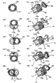
图7(b)和图7(c)是剖视图,显示了用于将连接件150安装至圆筒件147的连接件安装步骤。7( b ) and FIG. 7( c ) are cross-sectional views showing the attachment installation steps for attaching the
首先,连接件150沿着箭头X33的方向移动以便将驱动部150b插入容纳部147j。在插入之前,保持部150i的直径Z6大于由保持部147k的内边线147m(147m1-147m4)所构成的圆的直径D15(图7(a))。更具体地,满足Z6>D15的关系。First, the connecting
按照驱动部150b的插入,通过弹性变形,保持部(第一限制部)147k(147k1-147k4)临时回缩到空间147l中,该空间147l相对于圆筒件147的径向方向设置在外侧(图7c)。驱动部150b可以插入到容纳部147j中。这里,临时满足D15=Z6的关系。当完成驱动部150b插入容纳部147j时,已经弹性变形的保持部147k(147k1-147k4)恢复以前的状态。这里,满足Z6>D15的关系。According to the insertion of the driving
藉此,连接件150与圆筒件147彼此成为一体,因此提供一个驱动单元U1(图7d)。Thereby, the connecting
如图7e所示,侧盖157被沿着箭头X33的方向插入。藉此,整体形成在侧盖157上的保持部(第二限制部)157a进入圆筒件147的位于内表面和其自身之间的空间。更特别地,在保持部157a位于空间(间隙)147l中的状态下,侧盖157在其间置入支承件138地被安装至框架113。如图7(f)所示,藉此,防止圆筒件147的保持部147k(147k1-147k4)径向向外弹性变形。因此,这能够防止连接件150从圆筒件147脱离。根据本实施例,在将侧盖157安装至框架113的过程中,保持部157a位于空间(间隙)147l中。因此,改进了盒B的装配操作性。更特别地,能够改进将侧盖157安装至框架113的操作性。根据本实施例,具有以下两种用于将侧盖157安装至框架113的方法。在第一种方法中,在将支承件138安装至框架113之后,侧盖157被安装至框架113(图13(b))。在第二种方法中,支承件138和侧盖157彼此成为一体,然后它们被安装至框架113(图20(b))。在任何方法中,根据本实施例,能够改进盒B的装配操作性。As shown in FIG. 7e, the
保持部147k可以与侧盖157不是一体的,而是作为单独的连接件保持件。The holding
以这种方式,连接件150在圆筒件147中在旋转力传递角位置与预接合角位置之间以及在旋转力传递角位置与脱离角位置之间被可移动地、可枢转地、可回转地安装。In this way, the connecting
正如之前已经描述的,本实施例的盒B包括连接件(连接构件)150,用于在盒B安装在主组件A中的状态下从主组件A接收用于旋转显影辊110的旋转力。它具有可在内侧移动地支撑连接件150的一个端部(驱动部150b)的圆筒件147。圆筒件147的内侧设有圆筒侧力接收部(旋转力接收部)147h(147h1、147h2),用于接收通过连接件150从主组件A接收的旋转力。圆筒件147的外周面设有齿轮(第一齿轮)147a,用于将通过力接收部147h接收的旋转力传递至显影辊110。As has been described before, the cartridge B of the present embodiment includes a link (connection member) 150 for receiving a rotational force for rotating the developing
圆筒件147设有保持部(第一限制部)147k,用于防止作为安装至圆筒件147的连接件150的一个端部的驱动部150b沿着圆筒件147的轴向方向分离。圆筒件147的轴向方向是与位于旋转力传递角位置的连接件150的轴线L2相同的方向。这里,保持部147k被设置成沿着圆筒件147的径向方向可变形。保持部147k被设置在圆筒件147的内侧。圆筒件147的内侧意味着相对于轴向方向圆筒件147的端部的内侧。The
设置保持部(第二限制部)157a,用于在连接件150的一个端部(驱动部150b)被安装至圆筒件147的内侧、同时保持部147k变形的状态下限制保持部147k(147k1-147k4)的变形。保持部157a被设置在侧盖157的内侧。侧盖157的内侧指的是在侧盖157被安装至框架113的状态下,它是内侧即框架113侧。保持部(第一限制部)147k由树脂材料制造,并且由于树脂材料的弹力可以沿着圆筒件147的径向方向变形。A holding portion (second restricting portion) 157a is provided for restricting the holding
多个保持部(第一限制部)147k沿着圆筒件147的圆周方向按照圆周方向设有间隔。保持部147k可以沿着径向方向变形。保持部147k以空间(间隙)147l(147l1或147l2)(图7(c)、(e)和(f))与圆筒件147的内表面分离。保持部(第二限制部)157a进入至少一个空间147l中,以便防止保持部147k相对于径向方向向圆筒件147的外方变形(图7(f))。另外,圆筒件147、旋转力接收面(圆筒侧力接收部)147h和保持部147k由树脂材料制造并且被整体地模塑。连接件150的驱动部150b(一个端部)是球形的。The plurality of holding portions (first restricting portions) 147 k are provided at intervals in the circumferential direction along the circumferential direction of the
为了防止连接件150与圆筒件147分离,保持部147k具有突起S。为了防止球形部与圆筒件147分离,突起S相对于径向方向向圆筒件147的内部突出。突起S防止球形部沿圆筒件147的轴向方向脱离(图7(c)和图8)。在侧盖157与支承件138连接的状态下,它覆盖圆筒件147,所述圆筒件147支撑连接件159的一个端部以便允许其旋转。In order to prevent the connecting
侧盖157设有保持部157a(图7(e)、(f))。保持部157a进入设置在圆筒件147的内表面与保持部147k之间的至少一个空间147l中。藉此,限制保持部147k的变形(图7(f))。根据本实施例,在将驱动部150b安装至圆筒件147内侧的过程中,保持部147k沿径向方向向外变形。藉此,允许驱动部150b进入圆筒件147中。以这种方式,能够将驱动部150b平稳地安装到圆筒件147中。另外,仅仅通过将侧盖157安装至框架113,保持部157a就进入空间147l中。因此,能够限制保持部147k的变形。反之,在从圆筒件147拆卸驱动部150b的过程中,保持部147k也沿径向方向向外变形。藉此,能够从圆筒件147平稳地拆下驱动部150b。The
用于将连接件150安装至框架113的连接件安装方法包括连接件的安装步骤和侧盖的安装步骤。在连接件的安装步骤中,当由树脂材料制造的保持部(第一限制部)147k相对于径向方向向外变形时,连接件150的一个端部被可移动地安装至圆筒件147的内侧。用于将侧盖157安装至框架113的侧盖的安装步骤具有以下步骤。圆筒件147插在支承件138和侧盖157之间。在连接件150的另一端部通过侧盖157的开口157j突出的状态下,侧盖157的保持部(第二限制部)157a进入至少一个空间(间隙)147l中。藉此,侧盖157被安装至框架113,使得它限制保持部(第一限制部)147k弯曲。The connector installation method for installing the
保持部147k被设置在沿圆筒件147的圆周方向具有间隔的位置的每一个处,并且可以沿径向方向变形。通过连接件的安装步骤,连接件150的一个端部被安装至圆筒件147的内侧。支承件138支撑着安装至框架113的所述一个纵向端部的轴部110a(显影辊110的所述一个纵向端部的轴部110a)。空间(间隙)147l是位于圆筒件147的内表面与保持件147k之间的至少一个空间(间隙)147l。The holding
用于从框架113拆卸连接件150的连接件拆卸方法包括侧盖移除步骤和连接件移除步骤。侧盖拆卸是用于从框架113拆卸侧盖157的步骤。这里,侧盖157被安装至框架113,同时使得支撑连接件150的圆筒件147插在侧盖157和支承件138之间。侧盖157处于连接件150的另一端部通过开口157j突出的状态,并且被安装至框架113。侧盖157被安装至框架113,从而通过使侧盖157的保持部157a进入圆筒件147的内表面与保持部147之间的至少一个空间147l中而限制保持部147k的变形。连接件拆卸步骤是用于从圆筒件147拆下连接件150的步骤。连接件拆卸步骤是在执行将侧盖157从框架113拆下的侧盖拆卸步骤之后执行的。当从圆筒件147拆下连接件150时执行连接件拆卸步骤,同时沿圆筒件147的径向方向向外变形保持部147k。The connector detaching method for detaching the
在侧盖157的安装步骤中,在通过侧盖157的弹簧159的弹力而使得连接件150抵靠于倾斜限制部157n的状态下,执行侧盖157至框架113的安装。侧盖157与连接件150整体地一起安装至框架113。拆卸侧盖157的侧盖157拆卸步骤也在类似状态下被执行。由于侧盖157和连接件150能够在该步骤中被整体地安装至框架113,所以能够改进操作性。另外,能够改进移除操作性。In the mounting step of the
根据本实施例,在安装连接件150时,其被安装并且能够改进操作性。根据本实施例,在从盒B拆卸连接件150时,能够改进操作性。根据本实施例,在更换安装至盒B的连接件150时,能够改进更换操作性。根据本实施例,能够提供连接件150的更换方法,借助该方法,在更换安装至盒B的连接件150方面改进了更换操作性。According to the present embodiment, when the
藉此,通过沿轴线L2方向的单向运动的简单步骤,能够将连接件150安装至圆筒件147。以这种方式,在连接件150安装至盒B的状态下,连接件150在成像操作中不会从圆筒件147脱离。因此,能够防止图像缺陷的产生。Thereby, the connecting
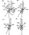
参照图9,将描述连接件150相对于圆筒件147的运动范围。Referring to FIG. 9 , the range of movement of the connecting
图9示出了圆筒件147和连接件150的连接状态。图9(a1)-(a5)是从驱动轴180看时的视图,并且图9(b1)-(b5)所显示的结构是透视图。FIG. 9 shows a connected state of the
如图9所示,这里,连接件150被安装至圆筒件147,从而其轴线L2能够相对于轴线L4沿所有方向倾斜。As shown in FIG. 9 , here, the connecting
在图9(a1)和(b1)中,轴线L2与轴线L4同轴。图9(a2)和(b2)显示了连接件150从该状态向上倾斜的状态。当连接件150朝着开口151g倾斜时,传递销155沿着开口151g移动(图9(a2)、(b2))。结果,连接件150围绕与开口151g的轴线垂直的轴线AX倾斜。In FIGS. 9( a1 ) and ( b1 ), the axis L2 is coaxial with the axis L4 . 9( a2 ) and ( b2 ) show a state where the connecting
图9(a3)和(b3)显示了连接件150向右倾斜的状态。因此,当连接件朝着开口151g倾斜时,销155在开口151g中旋转。在旋转时轴线L2是传递销155的轴线AY。9 ( a3 ) and ( b3 ) show a state where the connecting
图9(a4)、(b4)、图9(a5)、(b5)显示了连接件150向下倾斜的状态以及它向左倾斜的状态。连接件150围绕旋转轴线AX和AY倾斜。Fig. 9 (a4), (b4), Fig. 9 (a5), (b5) show the state in which the connecting
这里,沿着与所述倾斜方向不同的方向,发生围绕轴线AX的旋转和围绕轴线AY的旋转被结合在一起的倾斜运动。与倾斜方向不同的方向的例子被显示在图9(a2)、(a3)、(a3)、(a4)、(a4)、(a5)、(a5)和(a2)中。以这种方式,相对于轴线L4,轴线L2能够沿所有方向倾斜。Here, in a direction different from said tilting direction, a tilting movement occurs in which a rotation about the axis AX and a rotation about the axis AY are combined. Examples of directions other than the oblique direction are shown in FIGS. 9( a2 ), ( a3 ), ( a3 ), ( a4 ), ( a4 ), ( a5 ), ( a5 ), and ( a2 ). In this way, the axis L2 can be inclined in all directions with respect to the axis L4.
轴线L2已经被描述为可以相对于轴线L4沿任何方向倾斜。然而,轴线L2不是必须在360度的范围内可以沿任何方位相对于轴线L4倾斜至预定角度。在它不被满足的情况下,所必须的只是例如沿圆周方向更宽地形成开口147g。通过这种设置,当轴线L2相对于轴线L4倾斜时,线性倾斜预定量可能是不可以的,并且即使在这种情况下,连接件150也围绕轴线L2回转小的度数。藉此,轴线L2能够相对于轴线L4倾斜至预定角度。换言之,如果需要的话,可以合适地选择开口147g的旋转方向的游隙。The axis L2 has been described as being tiltable in any direction with respect to the axis L4. However, the axis L2 is not necessarily inclined to a predetermined angle relative to the axis L4 in any orientation within a range of 360 degrees. In a case where it is not satisfied, all that is necessary is to form the
正如之前已经描述的(图7),球形面150i与保持面147l接触。为此,连接件150被安装成球形面150i的球心P2为旋转中心。换言之,与圆筒件147的相位无关,轴线L2被可枢转地安装。As already described before (FIG. 7), the
接着,将描述一种限制方法,其用于恰好在接合之前相对于轴线L4沿旋转方向X4朝着下游侧倾斜轴线L2。Next, a restricting method for tilting the axis L2 toward the downstream side in the rotational direction X4 with respect to the axis L4 just before engagement will be described.
将参照图10(a)和图11描述连接件150的角位置限制部(“限制部“)160。图10(a)是从主组件侧看时限制部(倾斜限制部)160的透视图。图10(b)是从主组件侧看时限制部160的侧视图。图11(a)是一透视图,其显示了在连接件150占据驱动传递角位置(下面将被描述)的情况下连接件150与限制部160之间的位置关系。图11(b)是一透视图,其显示了在连接件150占据预接合角位置(下面将被描述)的情况下连接件150与限制部160之间的位置关系。图11(c)和图11(d)分别显示了在图11(a)和图11(b)的状态下圆筒件147和保持件156的状态。The angular position restricting portion ("restricting portion") 160 of the
限制部160具有支承部160a和限制部容纳部160b(图10)。限制部容纳部160b具有定位部160b1和自由部160b2。限制部160与支承件138成为一体。限制部160被设置在支承件138的外侧。支承件138的外侧是在支承件138被安装至框架113的状态下的外侧,并且它与框架相对。支承件138的外侧设有齿轮145、146和连接件150。The restricting
支承部160a可旋转地支撑圆筒件147的内表面147i(图7(b))。容纳部160b包含连接件150的连接件限制部150j。在这种状态下,连接件150可以在限制部150j不与容纳部160b的壁干涉的范围内自由地移动。The bearing
通过后面将要描述的扭转螺旋弹簧(连接件侧弹性材料)159的弹力将连接件150推动到预接合角位置。此时,限制部150j抵接定位部160b1,并且连接件150被定位在最佳预接合角位置以便开始与驱动轴180的接合。更特别地,定位部160b1仅仅在连接件150处于预接合角位置时用作定位部。The
在连接件150位于除预接合角位置之外的位置时,连接件150可以在限制部150j不与自由部160b2的内壁干涉的范围内自由地移动。在连接件150位于除预接合角位置之外的位置的情况下,连接件150位于预接合角位置与旋转力传递角位置之间的位置、位于旋转力传递角位置、位于旋转力传递角位置与脱离角位置之间的位置或者位于脱离角位置。When the
在连接件150从除预接合角位置之外的位置通过弹簧159的弹力移动至预接合角位置的情况下,限制部150j由自由部160b2的壁引导。并且限制部150j被引导至定位部160b1。连接件150到达预接合角位置。In the case where the
参照图12(a)和图12(b),将描述弹簧159。弹簧159在预接合角位置提供用于移动连接件150的推力。图12(a)是显示了弹簧159被安装至侧盖157的状态的透视图,并且图12(b)是盒B的透视图。Referring to Fig. 12(a) and Fig. 12(b), the
如图12(a)所示,弹簧支撑部157e1和弹簧旋转止动件157e2被设置在侧盖157的横侧面157i上。弹簧159的螺旋部159b被安装至支撑部157e1。弹簧159的旋转止动件臂159c抵接弹簧旋转止动件157e2。如图12(b)所示,弹簧159的接触部159c与连接件150的中间部150c接触。在该状态下,弹簧159被扭转以便产生弹力。通过该弹力推动中间部150c。藉此,连接件150的轴线L2相对于轴线L4倾斜(图12(b),预接合角位置)。弹簧159相对于中间部150c的接触位置被设置在相对于旋转方向X4、驱动部159b的中心的上游侧。为此,轴线L2相对于轴线L4倾斜,使得从动部150a侧相对于旋转方向X4朝向下游侧。As shown in FIG. 12( a ), a spring support portion 157e1 and a spring rotation stopper 157e2 are provided on the
在本实施例中,虽然扭转螺旋弹簧已经被用作弹性材料,但是这不是限制性的。它可以例如是片簧、橡胶、海绵等等,只要它能够产生弹力。然而,为了倾斜轴线L2,需要特定量的行程。为此,合乎期望的是一种构件,其能够容易地提供诸如预接合角位置这样的行程。In the present embodiment, although a torsion coil spring has been used as the elastic material, this is not restrictive. It can be, for example, a leaf spring, rubber, sponge, etc., as long as it can generate elastic force. However, in order to tilt the axis L2, a certain amount of travel is required. For this reason, it is desirable to have a member that can easily provide travel such as a pre-engagement angular position.
(连接件150安装至盒框架113)(
参照图13,将描述用于将连接件150安装至显影装置框架(盒框架)113的安装方法。图13(a)是在将弹簧159安装至圆筒件147之前盒B的透视图。图13(b)是在安装侧盖157和弹簧159之前盒B的透视图。图13(c)是在将弹簧159安装至侧盖157之前盒B的透视图。图13(d)是弹簧159已经安装至其上的盒B的透视图。Referring to FIG. 13 , a mounting method for mounting the connecting
支承件138、显影辊110和供应辊115被安装至框架113。此时,通过第一螺钉(第一紧固件)200c,支承件138被固定至显影装置框架113。另外,显影辊齿轮145被安装至一端轴部110a,显影辊齿轮145用于将旋转力从设置在圆筒件147上的齿轮147a传递至显影辊110。另外,供应辊齿轮146被安装至一端轴部115a,供应辊齿轮146用于将旋转力从设置在圆筒件147上的齿轮147b传递至供应辊110。所述一端轴部110a被设置在显影辊110的所述一个纵向端部,并且它被支承件138可旋转地支撑。所述一端轴部115a被设置在供应辊115的所述一个纵向端部,并且它被支承件138可旋转地支撑。另一端轴110b被设置在显影辊110的另一个纵向端部,并且它被支承件139可旋转地支撑。另一端轴115b被设置在供应辊115的另一个纵向端部,并且它被支承件139可旋转地支撑。藉此,显影辊110和供应辊115通过支承件138、139被框架113支撑。The
首先,具有被安装的驱动单元(连接件150)的圆筒件147被安装至限制部160(图13(b))。此时,执行安装(图11(b)),使得连接件限制部150j被安置在限制槽160b中。在该状态下,显影辊齿轮147a与齿轮145啮合,并且供应辊齿轮147b与齿轮146啮合。藉此,使得旋转力从圆筒件147传递至辊110、115。连接件150能够在连接件限制部150j不与限制部160中的限制部容纳部160b的壁干涉的范围内自由移动。First, the
然后,在圆筒件147置入支承件138与侧盖158之间的状态下,侧盖157被安装至框架113(图13(c))。在该安装操作中连接件150穿过侧盖157的开口157j,使得支承件138与侧盖157彼此接触。螺钉200b穿透侧盖157的通孔157f以及支承件138的通孔138f,并且被固定至设置在显影装置框架113上的螺钉接纳部113d(图27(a))。藉此,通过螺钉200b将侧盖157和支承件138相对于显影装置框架113紧固在一起。另外,螺钉200a穿透侧盖157的通孔157g,并且被固定至显影装置框架113的螺钉接纳部113g(图27(a))。藉此,通过螺钉200a将侧盖157固定至框架113。另外,螺钉200c穿透支承件138的通孔138g,并且被安装至框架113的螺钉接纳部113g(图27(a))。藉此,通过螺钉200c将支承件138固定至框架113。圆筒件147通过齿轮支撑部160a被可旋转地支撑。另外,通过保持部157a防止连接件150与圆筒件147分离。Then, the
最后,弹簧159被安装至侧盖157的弹簧支撑部157e1(图13(d))。执行该安装,使得连接件150的中间部150c抵接接触部159a的相对于弹簧159的推动方向的下游侧。在该状态下,连接件150通过弹簧159的弹力被推动以相对于旋转件C的旋转方向X4朝着下游侧倾斜。另外,限制部150j抵接限制槽160b的V型槽部160b1。更特别地,连接件150被大致固定至预接合角位置。Finally, the
这里,侧盖157设有弹簧159和倾斜限制部157n(图8),倾斜限制部157n限制通过弹簧159的弹力倾斜的连接件150的倾斜。侧盖157通过螺钉(第二螺钉)200a以及螺钉(第三螺钉)200b被安装至框架113。在这种情况下,连接件150能够与侧盖157整体地安装至框架113(图20(b))。这是因为连接件150通过弹簧159的弹力被压靠在限制部157n上,并且连接件150被侧盖157支撑。因此,改进了在将连接件150安装至框架113方面的操作性。另外,根据本实施例,连接件150、侧盖157和支承件138能够被整体地安装至框架(图20(b))。因此,能够改进在将连接件150、侧盖157和支承件138安装至框架113时的安装操作性。然而,本发明并不限制于该结构,而是这些可以被单独地安装至框架113。Here, the
另外,至于安装方法,在将圆筒件147安装至侧盖157之后,侧盖157可以被安装至框架113,本领域的普通技术人员能够合适地选择安装顺序。In addition, as for the mounting method, after the
(盒B相对于主组件的安装和拆卸方法)(How to install and remove box B relative to the main assembly)
参照图14-图15,将描述盒B相对于彩色电子照相成像设备的主组件A的安装和拆卸操作。14-15, the mounting and detaching operations of the cartridge B relative to the main assembly A of the color electrophotographic image forming apparatus will be described.
图14(a)是一剖视图,其显示了一个位置,该位置用于旋转件C从显影位置移动预定角相位而到达的位置,即盒安装和拆卸以及用于待机的位置。旋转件C除了在显影操作期间之外就占据该待机位置,并且盒B(B1-B4)的安装和拆卸操作也在该位置被执行。在本实施例中,显影位置上游45度的位置是待机位置。Fig. 14(a) is a sectional view showing a position for the position to which the rotary member C is moved by a predetermined angular phase from the developing position, that is, the position for cartridge mounting and detaching and for standby. The rotary member C occupies this standby position except during the developing operation, and the mounting and demounting operations of the cartridges B ( B1 - B4 ) are also performed at this position. In this embodiment, the position 45 degrees upstream of the developing position is the standby position.
当盒B(B1-B4)要被安装和拆卸时,使用者首先打开安装和拆卸盖13。藉此,使用者能够接近盒B(B1-B4)。四个盒B中的盒B1位于图14(a)中的安装和拆卸位置,并且盖13是打开的。盖13与互锁件SW(未示出)相关联地操作,并且互锁件SW通过解除盖而处于关闭。藉此,主组件A的驱动被搁置。同时,通过解除盖13,弹簧(未显示)的弹力使沿图中箭头的方向被推动的盒接合解除件19旋转。解除件19按压盒锁定件(未示出)。这将锁定件(未显示)移动至不与作为盒B的待锁定部的引导部60b接合的位置。藉此,只有位于安装和拆卸位置的盒B1从旋转件C中被释放。然后,使用者能够安装和拆卸盒B1。When the box B ( B1 - B4 ) is to be installed and removed, the user first opens the installation and
当使用者关闭盖13时,如图1所示,设置在盖13上的突起13a逆时针旋转解除件119。藉此,解除件119被保持在它不与显影装置锁定件(未示出)接触的位置。因此,当互锁件SW处于打开时,所有盒B(B1-B4)当然位于锁定位置。为此,确定地避免了没有锁定盒B(B1-B4)就操作主组件A的麻烦。When the user closes the
将描述用于将盒安装至成像设备的操作。An operation for mounting the cartridge to the image forming apparatus will be described.
如图14(b)所示,当使用者抓持把手54时,大体通过盒的重心确定盒B的方位。该方位类似于在盒B越过主组件A的上部的开口30时所占据的方位。As shown in FIG. 14(b), when the user grasps the
沿着主组件引导件17确定盒B的安装轨迹,最终盒B被安装至旋转件C。如图15(a)所示,此时,固定至盒B的相对端的侧盖138、139的引导部60a、61a在主组件引导件17的限制肋17a、17b上被引导。如图15(a)所示,当盒B从引导件17移至旋转件C的内侧时,设置在盒B的相对端的引导部60a、61a的自由端与旋转件C的引导槽C2(图15(b))接合。在该状态下,通过使用者沿安装方向施力,盒B被移至旋转件C的内侧,并且它能够移至作为常规位置的显影辊的定位部(容纳部130A)。本实施例中的定位部是设置在两侧的引导部60a、61a的外周。The mounting trajectory of the cartridge B is determined along the
在将盒B从主组件A拆卸的过程中,按照与上述安装操作相反的顺序执行操作。In the process of detaching the cartridge B from the main assembly A, perform the operations in reverse order of the above-mentioned installation operations.
参照图16-图20,将描述连接件的接合操作、旋转力传递操作和脱离操作。图16是驱动轴180、连接件150和圆筒件147的纵向剖视图。图17是纵向剖视图,其显示了驱动轴180、连接件150和圆筒件147之间的相位差。图18是驱动轴180、连接件150和圆筒件147的透视图。图19是显示了驱动轴180、连接件150和圆筒件147的纵向剖视图。图22(a)是驱动单元的侧视剖视图,并且图22(b)和(c)是显示了驱动单元的拆卸过程的透视图。Referring to FIGS. 16-20 , an engaging operation, a rotational force transmitting operation, and a disengaging operation of the link will be described. FIG. 16 is a longitudinal sectional view of the
在将盒B安装至显影位置的过程中,通过旋转旋转件C,连接件150位于预接合角位置。更特别地,通过弹簧159的弹力(推力),连接件150的轴线L2倾斜,使得从动部150a相对于旋转件C的旋转方向X4位于圆筒件147的轴线L4的下游。在本实施例中,轴线L2被定位在显影辊110和供应辊115之间。轴线L2关于以下圆的切线朝着旋转件C的旋转方向X4(图4)的下游相对于旋转件C的径向方向向外倾斜,所述圆与旋转件C同心并且穿过驱动部150b的中心。During installation of the cartridge B to the developing position, by rotating the rotary member C, the
通过连接件150的倾斜,沿轴线L4的方向,相对于旋转件C的旋转方向X4的下游自由端位置150A1比驱动轴180的自由端180b3更靠近圆筒件147。另外,相对于方向X4的上游自由端位置150A2沿轴线L4的方向比自由端180b3更靠近销182(图16(a)、(b))。这里,在图6(a)、(c)所示的连接件150的从动部150a的各部分中,相对于轴线L2的方向,自由端位置最靠近驱动轴并且最远离轴线L2。换言之,根据连接件150的旋转相位,它是从动部150a的一条边线或者非驱动突起150d的一条边线(图6(a)、(c)、150A)。By the inclination of the connecting
首先,相对于旋转件C的旋转方向X4的下游自由端位置150A1越过自由端180b3。在越过自由端180b3之后,连接件150的接收面150f或者突起150d与自由端180b3或销182接触。First, the downstream free end position 150A1 with respect to the rotation direction X4 of the rotary member C goes beyond the free end 180b3. After passing over the free end 180b3 , the receiving
因此,它朝着旋转件C的旋转倾斜(图16(c)),使得轴线L2平行于轴线L4。这里,旋转件C被临时搁置在图16(c)所示的状态中。此时,连接件150位于预接合角位置与驱动传递角位置之间的一位置。如果连接件150的两个突起和销182在该角位置接触,则旋转力能够被传递。当旋转件C停歇时,驱动轴180开始旋转。定位在入口部150k的销182进入相对于突起150d的间隙中。取决于连接件150与驱动轴180之间的旋转相位差,在该临时停歇期间,旋转力从驱动轴180传递至连接件150。最迟在到达下述旋转件C的位置(图16(d))之前,开始旋转力从驱动轴180到连接件150的传递。Therefore, it is inclined towards the rotation of the rotary member C ( FIG. 16( c )), so that the axis L2 is parallel to the axis L4 . Here, the rotary member C is temporarily left in the state shown in FIG. 16(c). At this time, the connecting
最后,相对于主组件A确定盒B的位置。更特别地,旋转件C停止。在这种情况下,驱动轴180的轴线L3与圆筒件147的轴线大致同轴。换言之,它从预接合角位置朝着旋转力传递角位置移动、倾斜、摆动、回转,使得允许连接件150的自由端位置150A1绕过驱动轴180。连接件150从预接合角位置朝着旋转力传递角位置倾斜、摆放、回转,使得轴线L2与轴线L4同轴。这里,连接件150和驱动轴180彼此接合(图16(d))。藉此,凹部150z覆盖自由端部180b。因此,旋转力从驱动轴180被稳定地传递至连接件150。此时,销155位于开口147g中,并且销182位于入口部150k中。Finally, the position of cartridge B relative to main assembly A is determined. More specifically, the rotary C stops. In this case, the axis L3 of the
另外,在本实施例中,驱动轴180已经在连接件150与驱动轴180开始接合的状态下旋转。为此,连接件150立即开始旋转。In addition, in the present embodiment, the
正如之前已经描述的,根据本实施例,连接件150可以相对于轴线L4倾斜。因此,通过连接件150相应于旋转件C的旋转的倾斜,连接件150能够平稳地与驱动轴180接合或连接。As has been described before, according to this embodiment, the
另外,在本实施例中,正如之前已经描述的,驱动轴180总是旋转。换言之,在接合操作时,驱动轴180的相位总是改变,并且驱动轴180与连接件150之间的相位关系采取各种关系。上述连接件150的接合操作是可以与驱动轴180和连接件150之间的相位关系无关的。参照图17,将对此进行描述。图17显示连接件和驱动轴的相位。在图17中,(a)显示了在相对于旋转件C的旋转方向X4的上游侧,销182与接收面150f彼此相对的状态。在图17中,(b)显示了销182与突起150d彼此相对的状态。在图17中,(c)显示了自由端部180b与突起150d彼此相对的状态。在图17中,(d)显示了自由端部180b与接收面150f彼此相对的状态。In addition, in the present embodiment, the
如图9所示,连接件150被安装至圆筒件147,使得它们可以相对于圆筒件沿所有方向枢转(回转和移动)。为此,如图17所示,连接件150可以沿安装方向X4倾斜,而与圆筒件147的相位无关。与驱动轴180与连接件150的相位关系无关,相对于旋转件C的旋转方向的下游自由端位置150A1为相对于旋转件C的旋转方向X4、驱动轴180的自由端180b3的下游。相对于旋转方向X4的上游自由端位置150A2通过连接件150的倾斜角而设定,使得它比自由端180b3更靠近销182。As shown in FIG. 9, the
通过这种设置,根据旋转件C的旋转操作,相对于旋转方向X4的下游自由端位置150A1越过自由端180b3。在图17(a)的情况下,接收面150f与销182接触。在图17(b)的情况下,突起150d与销182接触。在图17(c)的情况下,突起150d与自由端部180b接触。在图17(d)的情况下,接收面150f与自由端部180b接触。另外,通过旋转件C旋转时所产生的接触力(推力),轴线L2变得与轴线L4平行,从而它们彼此接合或连接。因此,与驱动轴180与连接件150之间的相位关系以及连接件150与圆筒件147之间的相位关系无关,它们能够彼此接合。With this arrangement, according to the rotation operation of the rotary member C, the downstream free end position 150A1 with respect to the rotation direction X4 goes beyond the free end 180b3. In the case of FIG. 17( a ), the receiving
参照图18,将描述在旋转显影辊110时的旋转力传递操作。通过从马达(未示出)接收的旋转力,沿图中箭头X8的旋转方向,驱动轴180与齿轮(斜齿轮)181一起旋转。与驱动轴180成为一体的销182与接收面150e1、150e2接触以便旋转连接件150。通过旋转连接件150,旋转力经由圆筒件147被传递到安装至显影辊110的轴部110b的显影齿轮145以便旋转显影辊110。Referring to FIG. 18 , the rotational force transmission operation when the developing
另外,即使轴线L3和轴线L4从共轴线稍微偏离,连接件150也将倾斜相应的角度,使得无需向显影辊110和驱动轴180施加大的载荷,就能通过连接件旋转它。In addition, even if the axis L3 and the axis L4 deviate slightly from the coaxial line, the
参照图19,将描述响应于由旋转件C沿一个方向的旋转而使得盒B从预定位置(显影位置)的运动,连接件150从驱动轴180脱离时的操作。Referring to FIG. 19 , the operation when the
首先,将描述在盒B从预定位置移动时每个销182的位置。正如从前面描述显而易见的,当完成成像时,销182位于入口部150k1、150k2中。销155位于开口150g1或150g2中。First, the position of each
当盒B所应用的成像操作完成时,前进到下一个盒B所使用的成像操作,并且与该切换操作相关联,连接件150从驱动轴180上被释放。将描述该操作。When the imaging operation applied by the cartridge B is completed, the imaging operation used by the next cartridge B is advanced, and in association with this switching operation, the connecting
在刚刚完成成像操作之后,连接件150占据旋转力传递角位置,其中轴线L2与轴线L4大致同轴(图19(a))。圆筒件147沿旋转方向X4与盒B一起移动。并且,相对于旋转方向X4的上游接收面150f或突起150d与驱动轴180的自由端部180b或销182接触。轴线L2开始朝着旋转方向X4(图19(b))的上游侧倾斜。该倾斜的方向是相对于圆筒件147与连接件150和驱动轴180接合时连接件150倾斜的方向相反的方向。通过该旋转件C的旋转操作,上游自由端部150A2一边与自由端部180b接触一边沿旋转方向X4移动。连接件150倾斜直到轴线L2的上游自由端部150A2到达自由端180b3(脱离角位置,图19(c))。在该状态下,连接件150在与轴的自由端180b3接触的同时越过自由端180b3(图19(d))。更特别地,连接件150从旋转力传递角位置移至脱离角位置,使得相对于旋转方向X4位于驱动轴180上游侧的连接件150的一部分(上游自由端位置150A2)被允许绕过驱动轴180。以这种方式,盒B按照旋转件C的旋转而移动。Immediately after the imaging operation is completed, the
在旋转件C的旋转一整圈之前,通过上述弹簧159的推力,连接件150的轴线L2相对于旋转方向X4朝着下游倾斜。换言之,连接件150从脱离角位置移至预接合角位置。通过这样做,在旋转件C的旋转一圈之后再次建立连接件150可以与驱动轴180接合的状态。Before the rotating member C rotates one full turn, the axis L2 of the connecting
连接件150的旋转力传递角位置是在将盒B定位在预定位置(与感光鼓107相对的位置)时、连接件150相对于轴线L4的一个角位置,在该位置,连接件150能够从驱动轴180接收旋转力并且它能够被旋转。连接件150的预接合角位置是在盒B按照旋转件C的旋转移至预定位置的过程中在连接件150刚要与驱动轴180接合之前、连接件150相对于轴线L4的一个角位置。连接件150的脱离角位置是在盒B按照旋转件C的旋转从预定位置移动的过程中在连接件150与驱动轴180脱离的情况下、连接件150相对于轴线L4的角位置。轴线L4是圆筒件147的旋转轴线,并且是齿轮147a、147b的旋转轴线。轴线L4大致平行于轴线L1。The rotational force transmission angular position of the
连接件是具有将旋转力(驱动力)从一个轴传递至另一个轴的功能的构件,并且它也被称为轴连接件。用在本实施例中的连接件的结构并不限于连接件150的结构,而是其它合适的结构也适用。A link is a member having a function of transmitting rotational force (driving force) from one shaft to another, and it is also called a shaft link. The structure of the connector used in this embodiment is not limited to the structure of the
如图20(a)所示,侧盖157的保持部157a被设置以防止设置在圆筒件147中的保持部147k的变形,保持部157a可以并不被设置在同一圆周的整个区域上。例如,可以省略一部分。保持部147k可以相对于保持部157a旋转。因此,与保持部147k的相位无关,只要保持部157a被设置在能够防止彼此面对的至少一对保持部(例如147k1和147k3)的变形的相位,就是令人满意的。As shown in FIG. 20( a), the retaining
显影辊110的拆卸方法How to remove the developing
参照图20,将描述本实施例中的显影辊110的拆卸方法。该图是显示盒的拆卸过程的透视图。Referring to Fig. 20, a detaching method of the developing
如前面描述所示,在盒B的所述一个纵向端部,螺钉200b将侧盖157和支承件138一起固定至框架113。螺钉200a将侧盖157固定至框架113。螺钉200c将支承件138固定至框架113。这里,如图3(a)和图27所示,侧盖157设有与螺钉200c同轴的通孔157h。孔157h的外径Z30比螺钉200c的外径更大。因此,能够移除螺钉200c,而无需拆卸侧盖157。能够通过将螺丝刀(工具)插入孔157h而移除螺钉200c。藉此,能够沿一个方向同时(一系列操作)将螺钉200a、200b、200c从盒B移除。通过如此做,整体部分U2(图20(b))(侧盖157、支承件138、驱动单元U1、齿轮145和齿轮146)能够沿箭头Y3的方向被同时拆卸。As shown in the foregoing description, at the one longitudinal end of the cartridge B, the
另外,在盒B的另一纵向端部,能够通过拆卸螺钉200f、200e沿箭头Y4的方向将支承件139从框架113拆除。In addition, at the other longitudinal end of the cartridge B, the
下面是盒B的拆卸方法。侧盖157和支承件138、139通过以下步骤从框架113被拆除。The following is the disassembly method of box B. The
为了从框架113拆除侧盖157,移除螺钉(第二螺钉)200a。为了从框架113拆除支承件138,相对于框架113的纵向方向从侧盖157的外侧通过设置在侧盖157中的孔157h移除螺钉(第一螺钉)200c。为了从框架113拆卸侧盖157和支承件113,移除螺钉(第三螺钉)200b。为了从框架113拆卸支承件139,移除螺钉(第四螺钉)200d。为了从框架113拆除支承件139,移除螺钉(第五螺钉)200f。In order to detach the
藉此,能够从框架113拆卸支承件138、支承件139和侧盖157。根据该方法,能够高效地从框架113拆卸支承件138和侧盖157。这是因为能够通过一系列操作拆卸螺钉200a、b、c。移除步骤的顺序并不限于上述顺序。然而,上述顺序是优选的,因为能够高效地从框架113拆除支承件138和侧盖157。这是因为最后拆除将侧盖157和支承件138一起紧固至框架113的螺钉200b。藉此,能够从框架113同时拆除侧盖157和支承件138。Thereby, the
能够通过上述步骤从框架拆除显影辊110和供应辊115。根据该方法,能够迅速地从框架113拆除显影辊110(供应辊115)。换言之,能够改进将显影辊110(供应辊115)从框架113拆除的操作性。在制造新的盒B的情况下,能够以与上述顺序相反的顺序快速地将显影辊110(供应辊115)安装至框架113。能够改进将显影辊110(供应辊115)安装至框架113的操作性。在再使用显影辊110(供应辊115)的情况下,能够提供类似的效果。然而,同样,本实施例并不限制于再使用显影辊110(供应辊115)的情况,在制造新的盒B的情况下,也提供上述有利效果。The developing
在本实施例中,已经描述用于将支承件138和侧盖157固定至框架113的构件为螺钉。然而,这不是限制性的。例如可以使用铆钉等代替螺钉作为紧固件。In the present embodiment, it has been described that the means for fixing the
在再使用显影辊110的情况下,通过这些步骤拆卸的显影辊110经受诸如检查和清洁等步骤。如果作为检查的结果没有缺陷,则将再使用显影辊110。在再使用显影辊110的情况下,显影辊110可以被再安装至被去除显影辊的那个盒B(框架113)上。或者,它可以被安装至另一盒B(框架113)。在再使用框架113(显影剂容纳部114)的情况下,显影剂被重新填充到显影剂容纳部114中。在执行重新填充显影剂的情况下,在重新填充之前进行框架113(显影剂容纳部114)的清洁。在再使用显影辊110的情况下,可以使用新的框架113(显影剂容纳部114)。另外,在再使用供应辊115的情况下,上述显影辊的情况同样适用。如果显影辊110和供应辊115不被再使用,则拆卸操作是不必要的。In the case of reusing the developing
在制造新的盒B的情况下,以与上述步骤相反的顺序将显影辊110和供应辊115安装至框架113。在执行对盒B的重新填充的情况下,通过上述过程一度将盒B拆卸。如果这些部件(显影辊110、供应辊115、框架113等等)被检查并且作为检查的结果没有发现对于再使用的缺陷,则这些部件将被再使用。在再使用这些部件的情况下,其部件可以被安装至与被去除这些部件的那个盒B(框架113)不同的另一盒B(框架113)上。或者,它可以被再附接至部件从其上拆卸的盒B本身上。In the case of manufacturing a new cartridge B, the developing
可以从被从框架113拆除的整体部U2中取出齿轮单元U1,并且只有已经特别磨损很大程度的连接件150可以用新的连接件更换。如图22所示,通过相对于圆筒件147沿箭头Y2的方向移动连接件150,圆筒件147的保持部147k变形。藉此,能够从圆筒件147容易地拆除连接件150(图21)。因此,只有磨损的连接件150通过简单的步骤被更换,并且能够应用其它可再生部件进行再装配。The gear unit U1 can be taken out of the integral part U2 which has been dismantled from the
在本实施例中,虽然已经描述了显影盒,但是它不是限制性的。例如,本发明能够应用于感光鼓和可作用在感光鼓上的其它处理件被整体地构成的所谓的处理盒。In this embodiment, although the developing cartridge has been described, it is not restrictive. For example, the present invention can be applied to a so-called process cartridge in which a photosensitive drum and other processing members that can act on the photosensitive drum are integrally formed.
图23是侧视图,显示了侧盖157和支承件138通过螺钉固定至框架113的状态。在图23中,(a)是侧视图,显示了本实施例。正如之前已经描述的,螺钉200a将侧盖157和框架113彼此固定。螺钉200b将侧盖157和支承件138共同紧固至框架113。螺钉200c将支承件138固定至框架113。螺钉200c能够通过例如经由孔157h进入的螺丝刀(工具)从侧盖157的外侧被固定及释放。正如之前已经描述的,侧盖157和支承件138被安装(固定、紧固)至框架113,正如以下将要描述的。Fig. 23 is a side view showing a state where the
通过螺钉(第一螺钉,第一紧固件)200c将支承件138安装至框架113。螺钉200c能够相对于框架113的纵向方向从侧盖157的外侧被固定至框架113。另外,能够从外侧进行移除操作。这是因为用于固定(释放)螺钉200c的螺丝刀能够通过设置在侧盖157中的孔157h被插入。换言之,螺钉200c经由设置在侧盖157中的孔157h进入,并且设置在支承件138中的通孔138g被穿透以便被固定至设置在框架113上的紧固部1113h。另外,能够通过例如经由孔157h插入的螺丝刀(工具)固定或释放螺钉200c。由这个结构提供下面将要描述的有利效果。The
侧盖157通过螺钉(第二螺钉,第二紧固件)200a被直接固定至框架113。另外,通过螺钉(第三螺钉,第三紧固件)200b,侧盖157与支承件138一起被固定至框架113。更特别地,它们被螺接在一起。通过这些结构提供后面将要描述的效果。在本实施例中,侧盖157设有孔157h,使得能够相对于框架113的纵向方向从侧盖157的外侧将支承件138固定至框架113。然而,本实施例并不限制于这个结构。例如,可以代替侧盖157中的孔,使用切掉部。然而,与提供切掉部相比,通过在侧盖157中提供孔这一结构,能够保持侧盖157的强度。另外,能够增加侧盖157覆盖齿轮145、146的面积。另外,能够增加侧盖157覆盖支承件138的面积。The
上述盒B的装配方法如下。用于将侧盖157和支承件138安装至框架113的方法如下。首先,通过螺钉(第一螺钉)200c相对于框架113的纵向方向,从侧盖157的外侧将支承件138直接固定至框架113。侧盖157通过螺钉(第二螺钉)200a被直接固定至框架113。通过螺钉(第三螺钉)200b将侧盖157与支承件138一起固定至框架113(图13(b),图23(a))。根据该方法,能够沿着框架113移动叠置的侧盖157和支承件138,并且能够借助螺钉200a、b和c通过一系列操作固定它们。因此,能够改进装配操作性。The assembly method of the above-mentioned cartridge B is as follows. A method for mounting the
通过螺钉200b将侧盖157与支承件138一起紧固至框架113。同样由此能够改进装配操作性。优选的是首先通过螺钉200b和200c将支承件138固定至框架113,然而,至于通过螺钉200a固定和通过螺钉200b固定的顺序,任何都是足够的。另外,在将支承件139安装至框架113的过程中,通过螺钉(第四螺钉)200d将支承件139直接固定至框架113。通过螺钉200e(第五螺钉)将支承件139直接固定至框架113(图20(b)、(c))。The
参照图23(b)和(c)显示了本发明的另一实施例。在图23中,(b)显示了除螺钉200a、200c...之外使用螺钉200g、200f的例子。螺钉200g将支承件138固定至框架113。螺钉200g能够通过进入孔157n的螺丝刀(工具)从侧盖157的外部被固定和释放。螺钉200f将侧盖157固定至框架113。换言之,螺钉200g具有与螺钉200c类似的结构,并且螺钉200f具有与螺钉200a类似的结构。在本实施例中,侧盖157和支承件138不是一起被紧固。Another embodiment of the present invention is shown with reference to Figs. 23(b) and (c). In FIG. 23, (b) shows an
图23(c)显示了除螺钉200b、200c、200g之外使用螺钉200i的一个例子。螺钉200i将侧盖157和支承件138一起紧固至框架113。更特别地,在本实施例中,使用螺钉200b、200i,并且侧盖157和支承件138被一起紧固在两个位置。Fig. 23(c) shows an example of using a screw 200i in addition to the
更特别地,在本实施例中,相对于框架113的纵向方向,侧盖157被设置在外侧,支承件138被设置在内侧,并且它们被一起固定至框架113。根据本实施例,用于将支承件138固定至框架113的结构是这样的,即可以相对于框架113的纵向方向从侧盖157的外侧进行固定操作。更特别地,使用根据上述实施例的螺钉200c和孔157h以及螺钉200g和孔157n的结构。More specifically, in the present embodiment, with respect to the longitudinal direction of the
藉此,根据本实施例,在将侧盖157设置在外侧并将支承件138设置在内侧的同时将它们固定至框架113的过程中,能够从侧盖157的外侧进行螺钉紧固。另外,根据本实施例,能够通过一系列操作将侧盖157和支承件138螺钉固定至框架113,并且因此能够改进装配操作性。更详细地,在将支承件138螺钉紧固至框架113之后,没有必要进行将侧盖157至框架113的螺钉紧固、同时使侧盖157与框架113相对。Thereby, according to the present embodiment, screw fastening can be performed from the outside of the
根据本实施例,能够将两个构件138、157一起螺钉紧固至框架113。因此,对于两个构件138、157的单独安装操作是不必要的。在从框架113拆卸两个构件138、157的情况下,能够从侧盖157的外侧进行螺钉的拆卸操作,该螺钉将两个构件138、157固定至框架113。另外,能够作为一系列操作进行该螺钉的拆卸操作。According to this embodiment, it is possible to screw fasten the two
因此,能够在从框架113拆卸两个构件138、157方面改进操作性。另外,能够通过将两个构件157、138一起紧固至框架113而改进安装操作性。另外,在拆卸的情况下,能够改进移除操作性。Therefore, it is possible to improve operability in detaching the two
在上述实施例中,在连接件的安装方法以及盒的装配方法中,可以使用自动装配机(所谓的机器人),或者可以利用工具人工进行。另外,可以主要利用工具人工进行连接件的拆卸方法和盒的拆卸方法。然而,可以适当地使用自动装配机。In the above-described embodiments, in the mounting method of the connector and the assembling method of the box, an automatic assembling machine (so-called robot) may be used, or it may be performed manually using a tool. In addition, the detachment method of the connector and the detachment method of the case can be performed manually mainly using a tool. However, an automatic assembly machine may be suitably used.
根据上述实施例,在将连接件150安装至盒B的过程中,能够改进操作性。在从盒B拆卸连接件150的过程中,能够改进操作性。能够提供连接件150的安装方法,其中在将连接件150安装至盒B方面改进了安装操作性。另外,能够提供连接件150的拆卸方法,其中在从盒B拆卸连接件150方面改进了拆卸操作性。According to the above-described embodiments, in the process of attaching the
虽然已经参照这里所公开的结构描述了本发明,但是本发明并不限制于这里所阐述的细节,并且本申请旨在涵盖落入改进目的或者附属权利要求书的范围中的所有变型或改变。Although the invention has been described with reference to the structures disclosed herein, the invention is not limited to the details set forth herein and the application is intended to cover all modifications or changes which come within the purpose of improvement or within the scope of the appended claims.
Claims (12)
Applications Claiming Priority (3)
| Application Number | Priority Date | Filing Date | Title |
|---|---|---|---|
| JP2008-161117 | 2008-06-20 | ||
| JP2008161117 | 2008-06-20 | ||
| JP2008161117 | 2008-06-20 |
Related Child Applications (1)
| Application Number | Title | Priority Date | Filing Date |
|---|---|---|---|
| CN201110267924.4A Division CN102323730B (en) | 2008-06-20 | 2009-06-19 | Cartridge detachably mountable to a main assembly of an electrophotographic image forming apparatus |
Publications (2)
| Publication Number | Publication Date |
|---|---|
| CN101609298A true CN101609298A (en) | 2009-12-23 |
| CN101609298B CN101609298B (en) | 2011-11-09 |
Family
ID=41431432
Family Applications (4)
| Application Number | Title | Priority Date | Filing Date |
|---|---|---|---|
| CN2011102744436A Pending CN102323731A (en) | 2008-06-20 | 2009-06-19 | Cartridge, assembling method for cartridge, and disassemblying method for cartridge |
| CN2009101503079A Active CN101609299B (en) | 2008-06-20 | 2009-06-19 | Box, installation method for box and removal method for box |
| CN2009101503045A Active CN101609298B (en) | 2008-06-20 | 2009-06-19 | Box, installation method for connecting member and removal method for connecting member |
| CN201110267924.4A Active CN102323730B (en) | 2008-06-20 | 2009-06-19 | Cartridge detachably mountable to a main assembly of an electrophotographic image forming apparatus |
Family Applications Before (2)
| Application Number | Title | Priority Date | Filing Date |
|---|---|---|---|
| CN2011102744436A Pending CN102323731A (en) | 2008-06-20 | 2009-06-19 | Cartridge, assembling method for cartridge, and disassemblying method for cartridge |
| CN2009101503079A Active CN101609299B (en) | 2008-06-20 | 2009-06-19 | Box, installation method for box and removal method for box |
Family Applications After (1)
| Application Number | Title | Priority Date | Filing Date |
|---|---|---|---|
| CN201110267924.4A Active CN102323730B (en) | 2008-06-20 | 2009-06-19 | Cartridge detachably mountable to a main assembly of an electrophotographic image forming apparatus |
Country Status (3)
| Country | Link |
|---|---|
| US (10) | US8433219B2 (en) |
| JP (9) | JP4558083B2 (en) |
| CN (4) | CN102323731A (en) |
Cited By (14)
| Publication number | Priority date | Publication date | Assignee | Title |
|---|---|---|---|---|
| CN102478777A (en) * | 2010-11-30 | 2012-05-30 | 京瓷美达株式会社 | Toner supply apparatus, toner storage container, and image forming apparatus |
| CN103454893A (en) * | 2012-05-30 | 2013-12-18 | 富士施乐株式会社 | Structural member, image forming apparatus and drive transmitting mechanism |
| CN103454894A (en) * | 2010-01-28 | 2013-12-18 | 珠海赛纳打印科技股份有限公司 | Processing case |
| CN105404118A (en) * | 2011-06-10 | 2016-03-16 | 兄弟工业株式会社 | Developing Cartridge |
| CN106125533A (en) * | 2013-09-29 | 2016-11-16 | 珠海艾派克科技股份有限公司 | Axis deviation adjusting mechanism, rotary force driving assembly and processing box |
| CN106597824A (en) * | 2015-10-14 | 2017-04-26 | 佳能株式会社 | Electrophotographic photosensitive drum unit, cartridge, and flange member |
| CN107203113A (en) * | 2017-04-17 | 2017-09-26 | 上福全球科技股份有限公司 | Powder box and its transmission component |
| CN108957997A (en) * | 2018-07-27 | 2018-12-07 | 珠海天威飞马打印耗材有限公司 | Handle box |
| CN110426938A (en) * | 2013-09-12 | 2019-11-08 | 佳能株式会社 | Box and drum unit for electro-photographic image forming apparatus |
| CN111308875A (en) * | 2012-12-14 | 2020-06-19 | 佳能株式会社 | Process cartridge and image forming apparatus |
| US11392079B2 (en) | 2012-12-14 | 2022-07-19 | Canon Kabushiki Kaisha | Process cartridge and image forming apparatus |
| CN115494714A (en) * | 2013-12-06 | 2022-12-20 | 佳能株式会社 | Cartridge, process cartridge and electrophotographic image forming device |
| CN116184786A (en) * | 2017-12-13 | 2023-05-30 | 佳能株式会社 | Cartridge and Image Forming Device |
| US12551565B2 (en) | 2019-02-22 | 2026-02-17 | Brightgene Bio-Medical Technology Co., Ltd. | CD44 targeted multi-arm conjugate |
Families Citing this family (48)
| Publication number | Priority date | Publication date | Assignee | Title |
|---|---|---|---|---|
| AU2016238959B2 (en) * | 2006-12-22 | 2017-07-13 | Canon Kabushiki Kaisha | Process cartridge, electrophotographic image forming apparatus, and electrophotographic photosensitive drum unit |
| JP4498407B2 (en) * | 2006-12-22 | 2010-07-07 | キヤノン株式会社 | Process cartridge, electrophotographic image forming apparatus, and electrophotographic photosensitive drum unit |
| JP5311854B2 (en) * | 2007-03-23 | 2013-10-09 | キヤノン株式会社 | Electrophotographic image forming apparatus, developing device, and coupling member |
| JP5127584B2 (en) | 2008-06-20 | 2013-01-23 | キヤノン株式会社 | Drum unit and electrophotographic image forming apparatus |
| JP4558083B2 (en) * | 2008-06-20 | 2010-10-06 | キヤノン株式会社 | Cartridge, method for assembling the cartridge, and method for disassembling the cartridge |
| JP5495671B2 (en) * | 2008-08-27 | 2014-05-21 | キヤノン株式会社 | Developing cartridge and coupling member |
| CN102138108B (en) | 2008-09-01 | 2014-01-08 | 佳能株式会社 | Developing cartridge, process cartridge, and electrophotographic image forming apparatus |
| CA129970S (en) * | 2009-03-03 | 2009-11-17 | Toshiba Tec Kk | Coupling for toner cartridge |
| JP5751779B2 (en) * | 2009-10-30 | 2015-07-22 | キヤノン株式会社 | Developing device, developing cartridge, process cartridge, and image forming apparatus |
| JP5554963B2 (en) * | 2009-10-30 | 2014-07-23 | キヤノン株式会社 | Developing cartridge and process cartridge |
| JP5430349B2 (en) * | 2009-10-30 | 2014-02-26 | キヤノン株式会社 | Developer cartridge |
| DE202010018322U1 (en) * | 2010-01-28 | 2015-08-07 | Zhuhai Seine Technology Co., Ltd. | cartridge |
| JP4911228B2 (en) * | 2010-01-29 | 2012-04-04 | ブラザー工業株式会社 | Cartridge and image forming apparatus |
| JP4843112B1 (en) * | 2010-06-11 | 2011-12-21 | 株式会社リコー | Detachable device, developer container, and image forming apparatus |
| ES2711352T3 (en) | 2010-06-11 | 2019-05-03 | Ricoh Co Ltd | Information storage device, removable device, developer container and image forming device |
| US8644733B2 (en) * | 2011-03-29 | 2014-02-04 | Static Control Components, Inc. | Cartridge drive shaft gear |
| US8892004B2 (en) | 2011-03-29 | 2014-11-18 | Static Control Components, Inc. | Drive gear for extended drive shaft |
| JP2013029733A (en) * | 2011-07-29 | 2013-02-07 | Canon Inc | Cover member and cartridge |
| JP5884343B2 (en) | 2011-08-31 | 2016-03-15 | ブラザー工業株式会社 | Process cartridge and developer cartridge |
| JP5943716B2 (en) * | 2012-06-04 | 2016-07-05 | キヤノン株式会社 | Developer cartridge |
| CN102880025A (en) * | 2012-10-24 | 2013-01-16 | 富美科技集团有限公司 | Photosensitive drum driving assembly |
| JP2014115472A (en) | 2012-12-10 | 2014-06-26 | Canon Inc | Cartridge and manufacturing method for cartridge |
| US9696684B2 (en) | 2012-12-14 | 2017-07-04 | Canon Kabushiki Kaisha | Process cartridge and image forming apparatus |
| JP6242201B2 (en) * | 2012-12-14 | 2017-12-06 | キヤノン株式会社 | Process cartridge and image forming apparatus |
| US20140165761A1 (en) * | 2012-12-17 | 2014-06-19 | Mitsubishi Kagaku Imaging Corporation | Drive transmission part for image forming apparatus |
| US9182733B2 (en) | 2013-02-07 | 2015-11-10 | Canon Kabushiki Kaisha | Developer supply cartridge, process cartridge and image forming apparatus |
| JP6111992B2 (en) | 2013-11-18 | 2017-04-12 | ブラザー工業株式会社 | Developer cartridge |
| CN110703572B (en) * | 2014-01-06 | 2022-04-22 | 兄弟工业株式会社 | Developing cartridge with driving force receiving member |
| CN103885306B (en) * | 2014-03-10 | 2017-01-11 | 珠海天威飞马打印耗材有限公司 | Driving assembly, roller and processing box |
| CN105093871B (en) * | 2014-05-06 | 2017-12-29 | 纳思达股份有限公司 | A kind of power reception unit and handle box |
| KR101610191B1 (en) | 2014-05-07 | 2016-04-07 | 삼성전자주식회사 | imaging cartridge and electrophotographic image forming apparatus using the same |
| JP6376841B2 (en) * | 2014-05-23 | 2018-08-22 | キヤノン株式会社 | Cartridge and image forming apparatus |
| US9329517B2 (en) | 2014-09-30 | 2016-05-03 | Clover Technologies Group, Llc | Drive receiving member for an imaging cartridge |
| EP3702848B1 (en) | 2014-11-28 | 2024-07-03 | Canon Kabushiki Kaisha | Cartridge and electrophotographic image forming apparatus |
| JP6562655B2 (en) * | 2015-02-27 | 2019-08-21 | キヤノン株式会社 | Cartridge and image forming apparatus |
| KR102859791B1 (en) | 2015-02-27 | 2025-09-12 | 캐논 가부시끼가이샤 | Drum unit, cartridge and electrophotographic image forming apparatus |
| HUE052180T2 (en) | 2015-02-27 | 2021-04-28 | Canon Kk | Cartridge |
| JP6512864B2 (en) | 2015-02-27 | 2019-05-15 | キヤノン株式会社 | Cartridge, process cartridge, image forming apparatus |
| JP6800660B2 (en) * | 2015-10-14 | 2020-12-16 | キヤノン株式会社 | cartridge |
| CN106610576B (en) * | 2015-10-26 | 2019-08-09 | 中山诚威科技有限公司 | A kind of driven unit and handle box |
| JP6601731B2 (en) * | 2016-01-12 | 2019-11-06 | 株式会社リコー | Drive transmission device and image forming apparatus |
| CN107132746A (en) * | 2016-02-26 | 2017-09-05 | 中山诚威科技有限公司 | a processing box |
| JP6658132B2 (en) | 2016-03-11 | 2020-03-04 | ブラザー工業株式会社 | Developing cartridge and image forming apparatus |
| JP6508120B2 (en) * | 2016-05-09 | 2019-05-08 | 京セラドキュメントソリューションズ株式会社 | Toner container, toner supply device, and image forming apparatus |
| CA3034221A1 (en) | 2016-08-26 | 2018-03-01 | Canon Kabushiki Kaisha | Cartridge and image forming apparatus |
| US9588478B1 (en) | 2016-09-30 | 2017-03-07 | Roy Fan | Drive coupling and transmitting assembly for photosensitive drum and toner cartridges |
| JP6957205B2 (en) | 2017-05-31 | 2021-11-02 | キヤノン株式会社 | Cartridge and image forming equipment |
| KR20210024807A (en) | 2019-08-26 | 2021-03-08 | 휴렛-팩커드 디벨롭먼트 컴퍼니, 엘.피. | Replaceable cartridge with driven coupler |
Family Cites Families (303)
| Publication number | Priority date | Publication date | Assignee | Title |
|---|---|---|---|---|
| US899913A (en) | 1907-12-13 | 1908-09-29 | Hugh Robertson Shaw | Power-transmission universal joint. |
| US2300514A (en) | 1940-02-21 | 1942-11-03 | Westinghouse Electric & Mfg Co | Dial attaching device |
| US2292676A (en) | 1941-08-21 | 1942-08-11 | Leon F Thiry | Rubber ball and socket joint |
| US3406534A (en) | 1966-10-10 | 1968-10-22 | Chapper John | Universal coupling |
| US3490841A (en) | 1968-01-15 | 1970-01-20 | Ibm | Photoconductor drum locator |
| US3818380A (en) | 1969-03-28 | 1974-06-18 | R Tyre | Single component controlled rc bridge |
| US3815386A (en) | 1971-02-02 | 1974-06-11 | Kamyr Ab | Device for bleaching of cellulosic pulp |
| US3922883A (en) | 1974-10-03 | 1975-12-02 | Motorola Inc | Anti-backlash universal coupling |
| GB1533868A (en) | 1974-12-28 | 1978-11-29 | Ricoh Kk | Serial printing apparatus |
| US4167321A (en) | 1976-09-14 | 1979-09-11 | Olympus Optical Co., Ltd. | Photosensitive drum for electrographic apparatus |
| DE7903031U1 (en) | 1979-02-05 | 1979-07-12 | Basf Ag, 6700 Ludwigshafen | PRESSURE DEVICE FOR FLEXIBLE RECORDING CARRIERS, IN PARTICULAR SUCH IN CASES |
| US4433767A (en) | 1979-07-16 | 1984-02-28 | Thor Charles C | Power transmission mechanism |
| JPS5744224U (en) * | 1980-08-28 | 1982-03-11 | ||
| JPS57153844A (en) | 1981-03-05 | 1982-09-22 | Sato Co Ltd | Device for printing and pasting label |
| US4457738A (en) | 1982-04-19 | 1984-07-03 | Xerox Corporation | Anti-backlash double universal flexible coupling |
| JPS59116951U (en) | 1983-01-25 | 1984-08-07 | 京セラミタ株式会社 | Copy machine power transmission device |
| GB2141520B (en) | 1983-06-08 | 1986-08-28 | Xerox Corp | Drive shaft connector |
| JPS59228281A (en) | 1983-06-10 | 1984-12-21 | Fuji Xerox Co Ltd | Photosensitive body driving device of electrophotographic copying machine |
| US4451117A (en) | 1983-11-04 | 1984-05-29 | Goode Robert C | Digital watch magnifying element |
| JPS60249729A (en) | 1984-05-23 | 1985-12-10 | Fuji Xerox Co Ltd | Uncouplable two-freedom joint |
| US4833502A (en) | 1985-07-11 | 1989-05-23 | Canon Kabushiki Kaisha | Image forming apparatus having an image bearing member reciprocally movable in the direction of the rotational axis thereof |
| GB2180796B (en) | 1985-09-17 | 1990-05-09 | Canon Kk | Replaceable image bearing member for an image forming apparatus. |
| FR2587510B1 (en) | 1985-09-17 | 1991-01-11 | Canon Kk | IMAGE SUPPORT ELEMENT, PROCESS CARTRIDGE CONTAINING SUCH ELEMENT, AND IMAGE FORMING APPARATUS |
| US4835565A (en) | 1986-06-11 | 1989-05-30 | Ricoh Company, Ltd. | Image developing device for electrophotography |
| JPS634252A (en) * | 1986-06-24 | 1988-01-09 | Canon Inc | Process cartridge and image forming device using same |
| JPS63115630U (en) * | 1987-01-23 | 1988-07-26 | ||
| US4873549A (en) | 1987-03-03 | 1989-10-10 | Mita Industrial Co., Ltd. | Device for detecting the life of an image forming process unit, opening of a seal of the unit and attachment of the unit to an image forming apparatus |
| JPH0271278A (en) | 1988-09-06 | 1990-03-09 | Ricoh Co Ltd | image forming device |
| US4915493A (en) | 1989-01-04 | 1990-04-10 | Magna International Inc. | Automotive rear view mirror assembly |
| FR2645607B1 (en) | 1989-04-07 | 1991-08-16 | Nacam | QUICK DRIVE AND DRIVE SHAFT COUPLING DEVICE AND ITS APPLICATION, PARTICULARLY TO AN AUTOMOTIVE STEERING |
| JPH02304459A (en) | 1989-05-19 | 1990-12-18 | Hitachi Ltd | Drum driving device for electrophotographic printer |
| US5094651A (en) | 1989-06-28 | 1992-03-10 | Cornay Paul J | Universal joint having hemispherical cup-shaped yoke and exterior, lubricating ring |
| US5290203A (en) | 1989-07-25 | 1994-03-01 | Gkn Automotive, Inc. | Constant velocity universal joint having high stress resistance |
| JPH03125166A (en) | 1989-10-11 | 1991-05-28 | Ricoh Co Ltd | Developing device |
| US5128715A (en) | 1990-03-19 | 1992-07-07 | Fuji Xerox Co., Ltd. | Print cartidge and image forming apparatus employing the same |
| JPH03125166U (en) | 1990-03-30 | 1991-12-18 | ||
| JPH04119363A (en) | 1990-09-10 | 1992-04-20 | Konica Corp | Image forming device |
| JPH04240870A (en) | 1991-01-25 | 1992-08-28 | Canon Inc | Drive transmission device for color image forming equipment |
| US5210574A (en) | 1991-03-08 | 1993-05-11 | Mita Industrial Co., Ltd. | Photosensitive drum body-mounting mechanism including a drive coupling member with a coupling protrusion adapted to bite into the inner surface of the mechanism's photosensitive drum |
| JPH04119363U (en) | 1991-04-05 | 1992-10-26 | 株式会社ゼクセル | radial piston pump |
| KR940009803B1 (en) | 1991-08-08 | 1994-10-17 | 구인회 | Roller cam device |
| JP2549684Y2 (en) | 1991-08-28 | 1997-09-30 | 三洋電機株式会社 | Rotation transmission mechanism of electrophotographic device |
| JPH0527765U (en) * | 1991-09-13 | 1993-04-09 | 株式会社リコー | Development unit driving device for image forming apparatus |
| US5177854A (en) | 1991-10-03 | 1993-01-12 | Xerox Corp | Distortion-free method of mounting an end piece on a thin-walled hollow tube |
| JPH0530857U (en) | 1991-10-04 | 1993-04-23 | 富士通株式会社 | Photosensitive drum connection structure |
| JP3058213B2 (en) | 1991-12-26 | 2000-07-04 | エヌティエヌ株式会社 | Constant velocity universal joint |
| US5331373A (en) | 1992-03-13 | 1994-07-19 | Canon Kabushiki Kaisha | Image forming apparatus, process cartridge mountable within it and method for attaching photosensitive drum to process cartridge |
| JP3352155B2 (en) | 1992-06-30 | 2002-12-03 | キヤノン株式会社 | Process cartridge and image forming apparatus |
| EP0813119B1 (en) | 1992-06-30 | 2001-04-11 | Canon Kabushiki Kaisha | Process cartridge and image forming system |
| JP2999636B2 (en) | 1992-09-21 | 2000-01-17 | キヤノン株式会社 | Image forming device |
| JP3253186B2 (en) | 1992-09-24 | 2002-02-04 | キヤノン株式会社 | Method of joining engagement member to cylinder, cylinder member and process cartridge |
| EP0625729B1 (en) | 1993-05-20 | 1998-11-04 | Canon Kabushiki Kaisha | A process cartridge |
| JP3517263B2 (en) | 1994-02-03 | 2004-04-12 | Ntn株式会社 | Hydrostatic gas bearing spindle |
| JPH07217665A (en) | 1994-02-04 | 1995-08-15 | Sutanree Works Japan:Kk | Universal coupling and universal tool including universal coupling |
| JP3869868B2 (en) | 1994-04-27 | 2007-01-17 | キヤノン株式会社 | Process cartridge and image forming apparatus |
| JP3337859B2 (en) | 1994-04-26 | 2002-10-28 | キヤノン株式会社 | Process cartridge and image forming apparatus |
| US5583618A (en) | 1994-05-31 | 1996-12-10 | Matsushita Electric Industrial Co., Ltd. | Process cartridge and image generating apparatus |
| US5647802A (en) | 1994-06-02 | 1997-07-15 | Torvec, Inc. | Variable-angle gears |
| US5562357A (en) | 1994-08-10 | 1996-10-08 | Larry C. Y. Lee | Snap-fit ball joint |
| PL178324B1 (en) | 1994-09-26 | 2000-04-28 | Lippert Unipol Gmbh | Surface machining tool |
| AU3426895A (en) * | 1994-10-17 | 1996-05-02 | Canon Kabushiki Kaisha | Toner container, toner container assembling method, process cartridge, and electrophotographic image forming apparatus |
| JP3839932B2 (en) | 1996-09-26 | 2006-11-01 | キヤノン株式会社 | Process cartridge, electrophotographic image forming apparatus, electrophotographic photosensitive drum and coupling |
| JPH08292704A (en) | 1995-04-21 | 1996-11-05 | Canon Inc | Process cartridge and electrophotographic image forming apparatus |
| JP3315560B2 (en) | 1995-06-13 | 2002-08-19 | キヤノン株式会社 | Process cartridge, electrophotographic image forming apparatus, and method of mounting electrophotographic photosensitive drum |
| JP3323696B2 (en) | 1995-06-13 | 2002-09-09 | キヤノン株式会社 | Ground member, electrophotographic photosensitive drum, process cartridge, and electrophotographic image forming apparatus |
| JP3372719B2 (en) | 1995-07-11 | 2003-02-04 | キヤノン株式会社 | Process cartridge and image forming apparatus |
| JP3530644B2 (en) | 1995-07-31 | 2004-05-24 | キヤノン株式会社 | Developing frame, process cartridge, and electrophotographic image forming apparatus |
| JPH0962079A (en) * | 1995-08-25 | 1997-03-07 | Canon Inc | Toner refilling method for process cartridge and process cartridge |
| JP3402872B2 (en) | 1995-08-25 | 2003-05-06 | キヤノン株式会社 | Process cartridge regeneration method and process cartridge |
| JP3656667B2 (en) | 1995-12-08 | 2005-06-08 | セイコーエプソン株式会社 | Electrophotographic image carrier and image forming apparatus using the same |
| JPH09177807A (en) | 1995-12-21 | 1997-07-11 | Ricoh Co Ltd | Biaxial joint mechanism |
| JP3505020B2 (en) | 1995-12-26 | 2004-03-08 | Ntn株式会社 | Fixed type constant velocity universal joint |
| JP3293438B2 (en) * | 1995-12-28 | 2002-06-17 | 松下電器産業株式会社 | Drive transmission device |
| JP3372418B2 (en) | 1996-02-21 | 2003-02-04 | 株式会社リコー | Image forming device |
| US5809380A (en) | 1996-03-14 | 1998-09-15 | Matsushita Electric Industrial Co., Ltd. | Color image forming apparatus with plural color units |
| US5983055A (en) | 1996-03-19 | 1999-11-09 | Sharp Kabushiki Kaisha | Photosensitive element for electrophotography |
| US6240266B1 (en) | 1996-03-21 | 2001-05-29 | Canon Kabushiki Kaisha | Process cartridge and drum mount for photosensitive drum |
| US6226478B1 (en) | 1996-03-21 | 2001-05-01 | Canon Kabushiki Kaisha | Process cartridge having drive mount for photosensitive drum |
| US5749028A (en) | 1996-06-26 | 1998-05-05 | Xerox Corporation | Multi-size photoreceptor flange bearing |
| JP3332818B2 (en) | 1996-08-29 | 2002-10-07 | キヤノン株式会社 | Process cartridge, electrophotographic image forming apparatus, and connection terminal connection method |
| JP3363751B2 (en) * | 1996-08-29 | 2003-01-08 | キヤノン株式会社 | Process cartridge and electrophotographic image forming apparatus |
| JP3323754B2 (en) | 1996-08-30 | 2002-09-09 | キヤノン株式会社 | Process cartridge and electrophotographic image forming apparatus |
| JP3342362B2 (en) * | 1996-09-20 | 2002-11-05 | キヤノン株式会社 | Process cartridge and electrophotographic image forming apparatus |
| JP3745047B2 (en) | 1996-09-26 | 2006-02-15 | キヤノン株式会社 | Electrophotographic image forming apparatus and process cartridge |
| JP3492109B2 (en) | 1996-09-26 | 2004-02-03 | キヤノン株式会社 | Process cartridge and electrophotographic image forming apparatus |
| JP3869913B2 (en) | 1996-09-30 | 2007-01-17 | キヤノン株式会社 | Cylindrical member and process cartridge used in electrophotographic image forming apparatus |
| JP3352370B2 (en) | 1996-11-14 | 2002-12-03 | キヤノン株式会社 | Process cartridge and electrophotographic image forming apparatus |
| US5848334A (en) | 1996-11-18 | 1998-12-08 | Xerox Corporation | Drive coupling with plural intimate planar contact |
| JPH10222041A (en) * | 1996-12-03 | 1998-08-21 | Canon Inc | Process cartridge and electrophotographic image forming apparatus |
| JP3363727B2 (en) * | 1996-12-12 | 2003-01-08 | キヤノン株式会社 | Process cartridge, electrophotographic image forming apparatus, process cartridge assembling method, and waste toner container assembling method |
| JP3745111B2 (en) | 1997-03-18 | 2006-02-15 | キヤノン株式会社 | Coupling member, process cartridge, and process cartridge assembly method |
| JP3789040B2 (en) | 1997-03-28 | 2006-06-21 | キヤノン株式会社 | Electrophotographic image forming apparatus |
| JPH10331845A (en) | 1997-05-29 | 1998-12-15 | Minolta Co Ltd | Supporting mechanism of cylinder rotary body |
| JP3609919B2 (en) | 1997-06-19 | 2005-01-12 | 京セラミタ株式会社 | Shaft coupling for image forming apparatus |
| JPH1173010A (en) | 1997-07-03 | 1999-03-16 | Canon Inc | Developing cartridge and electrophotographic image forming apparatus |
| JP3728104B2 (en) | 1997-07-03 | 2005-12-21 | キヤノン株式会社 | Developing cartridge side cover and developing cartridge |
| JP3332813B2 (en) * | 1997-08-01 | 2002-10-07 | キヤノン株式会社 | Process cartridge and electrophotographic image forming apparatus |
| US6058280A (en) | 1997-11-14 | 2000-05-02 | Xerox Corporation | Molded quick change photoreceptor support |
| JPH11249495A (en) * | 1998-03-03 | 1999-09-17 | Canon Inc | Ground member, cylindrical member, process cartridge, electrophotographic image forming apparatus |
| JPH11249494A (en) | 1998-03-03 | 1999-09-17 | Canon Inc | Drum flange, cylindrical member, process cartridge, electrophotographic image forming apparatus |
| JPH11282326A (en) | 1998-03-26 | 1999-10-15 | Canon Inc | Process cartridge and electrophotographic image forming apparatus |
| US5845175A (en) | 1998-03-27 | 1998-12-01 | Xerox Corporation | Rigid interference gear mount for enhanced motion quality |
| US6152826A (en) | 1998-04-29 | 2000-11-28 | Hand Tool Design Corporation | Impact universal joint |
| JPH11325097A (en) | 1998-05-15 | 1999-11-26 | Koyo Seiko Co Ltd | Coupling structure of shaft and yoke |
| JP3439342B2 (en) | 1998-06-03 | 2003-08-25 | 京セラミタ株式会社 | Image forming device |
| US6615006B2 (en) | 1998-06-30 | 2003-09-02 | Steven Bruce Michlin | Electrical contact device for a developer roller |
| JP2000075732A (en) | 1998-08-28 | 2000-03-14 | Matsushita Electric Ind Co Ltd | Image forming unit and image forming apparatus |
| JP3673658B2 (en) | 1998-10-28 | 2005-07-20 | キヤノン株式会社 | Process cartridge and electrophotographic image forming apparatus |
| JP2000131945A (en) | 1998-10-26 | 2000-05-12 | Canon Inc | Developing device and process cartridge |
| JP3684092B2 (en) | 1998-10-26 | 2005-08-17 | キヤノン株式会社 | Electrophotographic image forming apparatus |
| JP3697090B2 (en) | 1998-10-26 | 2005-09-21 | キヤノン株式会社 | Electrophotographic image forming apparatus |
| JP2000170783A (en) | 1998-12-03 | 2000-06-20 | Canon Inc | Rotational force transmission mechanism, sheet feeding device, and image forming device |
| JP3796364B2 (en) * | 1999-01-27 | 2006-07-12 | キヤノン株式会社 | Electrophotographic image forming apparatus |
| US6330410B1 (en) | 1999-02-26 | 2001-12-11 | Brother Kogyo Kabushiki Kaisha | Photosensitive member cartridge |
| JP4219469B2 (en) | 1999-03-04 | 2009-02-04 | Ntn株式会社 | Constant velocity universal joint |
| JP3679645B2 (en) | 1999-03-29 | 2005-08-03 | キヤノン株式会社 | Process cartridge |
| JP2000280348A (en) | 1999-04-02 | 2000-10-10 | Canon Inc | Cylindrical member, electrophotographic photosensitive drum using the same, and process cartridge |
| US6336012B1 (en) | 1999-04-30 | 2002-01-01 | Canon Kabushiki Kaisha | Developing device, process cartridge and electric energy supply part to developing roller |
| JP3320398B2 (en) * | 1999-05-20 | 2002-09-03 | キヤノン株式会社 | Process cartridge and electrophotographic image forming apparatus |
| JP3748506B2 (en) * | 1999-05-20 | 2006-02-22 | キヤノン株式会社 | Process cartridge and process cartridge assembly method |
| JP3320399B2 (en) | 1999-05-20 | 2002-09-03 | キヤノン株式会社 | Process cartridge, method of assembling process cartridge, and electrophotographic image forming apparatus |
| US6118962A (en) | 1999-05-26 | 2000-09-12 | Xerox Corporation | Automatic camming of a developer module |
| SE9902207L (en) | 1999-06-11 | 2000-12-12 | Sca Hygiene Prod Ab | Use of moisture-tight packaging for absorbent articles containing moisture-sensitive additives |
| JP2001083753A (en) | 1999-09-14 | 2001-03-30 | Fuji Xerox Co Ltd | Image forming device |
| JP3188435B2 (en) * | 1999-10-29 | 2001-07-16 | キヤノン株式会社 | Reproduction method of process cartridge |
| JP3679665B2 (en) * | 1999-11-19 | 2005-08-03 | キヤノン株式会社 | Gap assurance member, developing device, charging device, and process cartridge |
| JP3478797B2 (en) * | 1999-12-28 | 2003-12-15 | キヤノン株式会社 | Process cartridge and electrophotographic image forming apparatus |
| JP2001194954A (en) | 2000-01-11 | 2001-07-19 | Fuji Xerox Co Ltd | Method of fixing packing member incorporated into electrophotographic photoreceptor, and electrophotographic photoreceptor, and process cartridge for electrophotography |
| US6549736B2 (en) | 2000-01-19 | 2003-04-15 | Canon Kabushiki Kaisha | Process cartridge, engaging member therefor and method for mounting developing roller and magnet |
| US6487278B1 (en) | 2000-02-29 | 2002-11-26 | Ameritech Corporation | Method and system for interfacing systems unified messaging with legacy systems located behind corporate firewalls |
| JP3188439B1 (en) | 2000-03-07 | 2001-07-16 | キヤノン株式会社 | Reproduction method of process cartridge |
| EP1162515B1 (en) | 2000-06-09 | 2011-04-27 | Canon Kabushiki Kaisha | Developing apparatus, process cartridge and flexible seal |
| JP3283501B2 (en) | 2000-06-28 | 2002-05-20 | キヤノン株式会社 | Process cartridge remanufacturing method |
| JP3716716B2 (en) | 2000-07-10 | 2005-11-16 | 富士ゼロックス株式会社 | Rotating body driving device and image forming apparatus using the same |
| JP4046933B2 (en) | 2000-08-02 | 2008-02-13 | キヤノン株式会社 | Drive transmission device and image forming apparatus having the same |
| US6549738B2 (en) | 2000-08-30 | 2003-04-15 | Oki Data Corporation | Image forming cartridge and image forming apparatus having a photoreceptor drum that rotates at a constant velocity and is stably grounded |
| JP2002182446A (en) | 2000-10-04 | 2002-06-26 | Canon Inc | Driving force transmitting component, electrophotographic photosensitive drum, process cartridge, and electrophotographic image forming apparatus |
| US6829455B2 (en) | 2000-10-20 | 2004-12-07 | Canon Kabushiki Kaisha | Driving force transmission mechanism, image forming apparatus equipped with such a mechanism, and process unit of such an apparatus |
| KR100402391B1 (en) | 2000-10-26 | 2003-10-22 | 삼성전자주식회사 | Memory card system |
| JP3432218B2 (en) * | 2000-10-31 | 2003-08-04 | キヤノン株式会社 | Process cartridge, load generating member, and electrophotographic image forming apparatus |
| US6490426B1 (en) | 2000-11-03 | 2002-12-03 | Xerox Corporation | Modular imaging member flange assembly |
| JP3667243B2 (en) | 2000-12-01 | 2005-07-06 | キヤノン株式会社 | Process cartridge, process cartridge mounting mechanism, and electrophotographic image forming apparatus |
| JP2002244382A (en) | 2000-12-13 | 2002-08-30 | Canon Inc | Process cartridge, electrical contact member, and electrophotographic image forming apparatus |
| JP3658315B2 (en) | 2000-12-19 | 2005-06-08 | キヤノン株式会社 | Process cartridge and electrophotographic image forming apparatus |
| JP4677093B2 (en) * | 2000-12-25 | 2011-04-27 | キヤノン株式会社 | Process cartridge |
| TW500949B (en) | 2000-12-26 | 2002-09-01 | Quanta Display Inc | Device and flow for in-line operation of liquid crystal display |
| US6654580B2 (en) | 2000-12-27 | 2003-11-25 | Matsushita Electric Industrial Co., Ltd. | Image forming apparatus |
| US6397029B1 (en) | 2001-01-11 | 2002-05-28 | Lexmark International, Inc | Coupler for an image-forming apparatus |
| JP3985453B2 (en) | 2001-01-12 | 2007-10-03 | 松下電工株式会社 | Power converter |
| JP3542583B2 (en) | 2001-02-02 | 2004-07-14 | キヤノン株式会社 | Process cartridge, electrophotographic photosensitive drum, electrophotographic image forming apparatus, and color electrophotographic image forming apparatus |
| US6699550B2 (en) | 2001-04-12 | 2004-03-02 | Bridgestone Corporation | Base-body for photosensitive drum and photosensitive drum with the use of the same |
| JP3564080B2 (en) | 2001-04-27 | 2004-09-08 | キヤノン株式会社 | Process cartridge remanufacturing method |
| JP3542569B2 (en) * | 2001-04-27 | 2004-07-14 | キヤノン株式会社 | Process cartridge remanufacturing method |
| JP3840063B2 (en) | 2001-04-27 | 2006-11-01 | キヤノン株式会社 | Process cartridge |
| JP4447191B2 (en) | 2001-09-12 | 2010-04-07 | 株式会社リコー | Bearing structure of drive mechanism, image reading apparatus, and image forming apparatus |
| JP2003162203A (en) | 2001-09-13 | 2003-06-06 | Canon Inc | Unit, developing cartridge, process cartridge, toner cartridge, and electrophotographic image forming apparatus |
| KR100381598B1 (en) | 2001-09-18 | 2003-04-26 | 삼성전자주식회사 | coupling apparatus and process cartridge and electrophotographic printer having the same |
| US6896440B2 (en) | 2001-09-24 | 2005-05-24 | Cardinal Ig Company | Connector for joining multiple pane window spacers |
| JP2003139221A (en) * | 2001-11-06 | 2003-05-14 | Funai Electric Co Ltd | Gear mounting structure |
| KR100423475B1 (en) | 2001-11-27 | 2004-03-18 | 삼성전자주식회사 | coupling apparatus |
| US6572480B1 (en) | 2001-12-05 | 2003-06-03 | Visteon Global Technologies, Inc. | Polygon universal joint |
| JP3793457B2 (en) | 2001-12-27 | 2006-07-05 | 京セラミタ株式会社 | Drive mechanism for image forming apparatus |
| US6795671B2 (en) | 2002-01-15 | 2004-09-21 | Canon Kabushiki Kaisha | Image forming apparatus featuring switchable, contact and spaced, clutch-operated developing units |
| JP2003215917A (en) | 2002-01-24 | 2003-07-30 | Canon Inc | Developing device, process cartridge and image forming apparatus |
| JP3595798B2 (en) | 2002-01-31 | 2004-12-02 | キヤノン株式会社 | Process cartridge and electrophotographic image forming apparatus |
| JP2003247535A (en) | 2002-02-26 | 2003-09-05 | Bridgestone Corp | Cylindrical supporting body |
| US7139604B1 (en) * | 2002-03-28 | 2006-11-21 | Pacesetter, Inc. | Cardiac stimulation system and method for discriminating sinus from non-sinus events |
| JP3997817B2 (en) | 2002-04-02 | 2007-10-24 | ブラザー工業株式会社 | Developing device and image forming apparatus |
| JP2003307992A (en) | 2002-04-17 | 2003-10-31 | Canon Inc | Process cartridge and electrophotographic image forming apparatus |
| JP2004045603A (en) | 2002-07-10 | 2004-02-12 | Konica Minolta Holdings Inc | Image forming apparatus |
| JP2004101690A (en) * | 2002-09-06 | 2004-04-02 | Canon Inc | Developing device, process cartridge, and electrophotographic image forming device |
| WO2004024418A1 (en) | 2002-09-13 | 2004-03-25 | Polymold Ag | Injection device used for blow molding hollow plastic bodies, comprising extrusion mandrels that can be tempered and are inserted into an extrusion mandrel fastener |
| JP3913153B2 (en) | 2002-09-30 | 2007-05-09 | キヤノン株式会社 | Power supply contact member, process cartridge, and image forming apparatus |
| JP3944045B2 (en) | 2002-09-30 | 2007-07-11 | キヤノン株式会社 | Developer supply container and electrophotographic image forming apparatus |
| JP4314006B2 (en) | 2002-09-30 | 2009-08-12 | キヤノン株式会社 | Image forming apparatus |
| JP2004144240A (en) | 2002-10-25 | 2004-05-20 | Ntn Corp | Tripod type constant velocity universal joint |
| JP2004151563A (en) * | 2002-10-31 | 2004-05-27 | Canon Inc | Process cartridge reproduction method |
| JP3970161B2 (en) | 2002-11-08 | 2007-09-05 | キヤノン株式会社 | Process cartridge remanufacturing method |
| WO2004046829A2 (en) | 2002-11-19 | 2004-06-03 | Himes William D | Developer cartridge including rim |
| JP2004177835A (en) | 2002-11-29 | 2004-06-24 | Canon Inc | Parts and how to supply parts |
| JP4018517B2 (en) | 2002-11-29 | 2007-12-05 | キヤノン株式会社 | parts |
| US6869366B2 (en) | 2002-12-19 | 2005-03-22 | Easco Hand Tools Inc. | Universal joint |
| JP2004198822A (en) | 2002-12-19 | 2004-07-15 | Fuji Xerox Co Ltd | Driving force transmitting device and image forming apparatus |
| JP4243100B2 (en) * | 2002-12-24 | 2009-03-25 | パナソニック株式会社 | Image forming apparatus |
| CN1205459C (en) | 2002-12-26 | 2005-06-08 | 上海华辰科技发展有限公司 | Culvert type flow meter |
| GB2397136A (en) | 2003-01-10 | 2004-07-14 | Gcc Man Ltd | A toner cartridge |
| JP2004246058A (en) | 2003-02-13 | 2004-09-02 | Fuji Xerox Co Ltd | Image forming apparatus |
| JP4228196B2 (en) | 2003-02-21 | 2009-02-25 | Nok株式会社 | Anti-vibration rubber for image forming drum and method of assembling the same |
| US7121205B2 (en) | 2003-03-14 | 2006-10-17 | Ricoh Company, Limited | Device for and method of coupling shafts, image formation apparatus, process cartridge, and belt unit |
| JP4005525B2 (en) * | 2003-03-26 | 2007-11-07 | 京セラミタ株式会社 | Image forming apparatus |
| EP1630625A4 (en) | 2003-05-22 | 2012-10-03 | Mitsubishi Chem Corp | LIGHT-SENSITIVE BODY DRUM, METHOD AND DEVICE FOR ASSEMBLING THE DRUM AND PICTURE PRODUCTION DEVICE WITH THE DRUM |
| JP4126254B2 (en) | 2003-06-30 | 2008-07-30 | 株式会社リコー | Image forming apparatus |
| JP4227488B2 (en) | 2003-08-29 | 2009-02-18 | キヤノン株式会社 | Drive transmission device and image forming apparatus |
| JP3970217B2 (en) | 2003-08-29 | 2007-09-05 | キヤノン株式会社 | Electrophotographic image forming apparatus |
| JP4681833B2 (en) | 2003-09-19 | 2011-05-11 | 株式会社リコー | Image forming apparatus |
| JP2005148445A (en) | 2003-11-17 | 2005-06-09 | Canon Inc | Developing device, process cartridge, electrophotographic image forming apparatus, and end regulating member |
| JP2005156654A (en) | 2003-11-21 | 2005-06-16 | Canon Inc | Charging device, process cartridge, and image forming apparatus |
| US7020410B2 (en) | 2003-11-21 | 2006-03-28 | Mitsubishi Chemical America, Inc. | Grounding plate assembly for a drum in an image forming apparatus |
| JP3782807B2 (en) | 2003-11-28 | 2006-06-07 | キヤノン株式会社 | Process cartridge and method for attaching electrophotographic photosensitive drum |
| JP3789122B2 (en) * | 2003-11-28 | 2006-06-21 | キヤノン株式会社 | Process cartridge remanufacturing method |
| JP4049736B2 (en) | 2003-11-28 | 2008-02-20 | 京セラミタ株式会社 | Image forming apparatus |
| JP4652783B2 (en) | 2003-12-10 | 2011-03-16 | キヤノン株式会社 | Developer supply container |
| JP4110143B2 (en) | 2004-01-30 | 2008-07-02 | キヤノン株式会社 | Electrophotographic image forming apparatus, unit detachable from electrophotographic image forming apparatus, and process cartridge |
| JP2005241946A (en) * | 2004-02-26 | 2005-09-08 | Konica Minolta Business Technologies Inc | Image forming apparatus and driving transmitting joint |
| US7228090B2 (en) | 2004-02-26 | 2007-06-05 | Konica Minolta Business Technologies, Inc. | Image forming apparatus with a removable process unit capable of securing rotation transmission accuracy without stressing a holding portion despite shaft misalignment |
| JP3885062B2 (en) * | 2004-03-30 | 2007-02-21 | キヤノン株式会社 | Electrophotographic photosensitive drum, process cartridge, and electrophotographic image forming apparatus |
| US7164875B2 (en) | 2004-03-30 | 2007-01-16 | Canon Kabushiki Kaisha | Electrophotographic image forming apparatus having a plurality of mounting portions for detachably mounting a plurality process cartridges |
| JP3970274B2 (en) | 2004-03-31 | 2007-09-05 | キヤノン株式会社 | Process cartridge and electrophotographic image forming apparatus |
| JP4656558B2 (en) | 2004-04-09 | 2011-03-23 | 株式会社三共 | Member service provision system |
| JP2005299788A (en) | 2004-04-12 | 2005-10-27 | Kyocera Mita Corp | Shaft joint and image forming device |
| JP4101248B2 (en) * | 2004-04-16 | 2008-06-18 | キヤノン株式会社 | Process cartridge remanufacturing method |
| US7158749B2 (en) * | 2004-04-26 | 2007-01-02 | Canon Kabushiki Kaisha | Cleaning device, process cartridge, cleaning member and electrophotographic image forming apparatus |
| JP4110128B2 (en) * | 2004-04-26 | 2008-07-02 | キヤノン株式会社 | Process cartridge, electrophotographic image forming apparatus and bearing member |
| JP2005316192A (en) * | 2004-04-28 | 2005-11-10 | Canon Inc | Electrophotographic image forming apparatus |
| JP3840232B2 (en) | 2004-05-06 | 2006-11-01 | キヤノン株式会社 | Process cartridge |
| JP3885074B2 (en) * | 2004-05-11 | 2007-02-21 | キヤノン株式会社 | Electrophotographic photosensitive drum, process cartridge, and electrophotographic image forming apparatus |
| JP4604550B2 (en) | 2004-05-24 | 2011-01-05 | ブラザー工業株式会社 | Image forming apparatus and process cartridge |
| CN100585220C (en) | 2004-06-22 | 2010-01-27 | 杉谷伸 | Gear mechanism, planetary gear device, rotary bearing device, and singular planetary gear reduction device |
| EP1610188B1 (en) | 2004-06-22 | 2012-03-07 | Brother Kogyo Kabushiki Kaisha | Image-forming device |
| US7366443B2 (en) | 2004-06-22 | 2008-04-29 | Ntn Corporation | Constant-velocity joint and image-forming device |
| US20050286933A1 (en) | 2004-06-28 | 2005-12-29 | Samsung Electronics Co., Ltd. | Roller for image forming apparatus and method of manufacturing same |
| US20060008289A1 (en) | 2004-07-06 | 2006-01-12 | Canon Kabushiki Kaisha | Electrophotographic image forming apparatus and process cartridge |
| EP1774411A2 (en) | 2004-07-26 | 2007-04-18 | GCC IP Pty Limited | Driving force member |
| JP2006039364A (en) | 2004-07-29 | 2006-02-09 | Canon Inc | Drum driving force transmission device, process cartridge, and electrophotographic image forming apparatus |
| JP3970279B2 (en) | 2004-07-30 | 2007-09-05 | キヤノン株式会社 | Process cartridge and electrophotographic image forming apparatus |
| US7457570B2 (en) | 2004-08-06 | 2008-11-25 | Ricoh Company, Ltd. | Image forming apparatus including a magnetic brush developing system using a two-component developer comprising toner and carrier |
| KR100605165B1 (en) | 2004-08-13 | 2006-07-28 | 삼성전자주식회사 | Image Forming Device |
| JP3826148B2 (en) | 2004-08-26 | 2006-09-27 | キヤノン株式会社 | Process cartridge and electrophotographic image forming apparatus |
| JP4431467B2 (en) * | 2004-09-03 | 2010-03-17 | 株式会社リコー | Image forming apparatus. |
| JP4617122B2 (en) | 2004-09-08 | 2011-01-19 | キヤノン株式会社 | Developer transport member, developing device, and process cartridge |
| JP4711755B2 (en) | 2004-09-13 | 2011-06-29 | Ntn株式会社 | Image forming apparatus |
| JP2006084935A (en) | 2004-09-17 | 2006-03-30 | Ricoh Co Ltd | Shaft coupling device, transmission device having the coupling device, and image forming apparatus having the transmission device |
| JP4621094B2 (en) | 2004-09-20 | 2011-01-26 | オセ−テクノロジーズ・ベー・ヴエー | Image alignment device |
| US7877043B2 (en) * | 2004-09-22 | 2011-01-25 | Ntn Corporation | Constant-velocity joint and image-forming device |
| JP4584089B2 (en) * | 2004-09-22 | 2010-11-17 | Ntn株式会社 | Constant velocity joint |
| US7289752B2 (en) | 2004-09-24 | 2007-10-30 | Ntn Corporation | Tripod type constant-velocity joint and image-forming device |
| JP4886182B2 (en) | 2004-09-27 | 2012-02-29 | キヤノン株式会社 | Cartridge, process cartridge, and electrophotographic image forming apparatus |
| JP3950883B2 (en) * | 2004-10-06 | 2007-08-01 | キヤノン株式会社 | Electrophotographic image forming apparatus |
| JP3950882B2 (en) * | 2004-10-06 | 2007-08-01 | キヤノン株式会社 | Electrophotographic image forming apparatus |
| JP4710476B2 (en) | 2004-10-28 | 2011-06-29 | ブラザー工業株式会社 | Image forming apparatus |
| JP2006133436A (en) | 2004-11-05 | 2006-05-25 | Oki Data Corp | Image forming apparatus |
| JP4799851B2 (en) | 2004-11-15 | 2011-10-26 | 株式会社リコー | Image forming apparatus |
| JP2006163298A (en) * | 2004-12-10 | 2006-06-22 | Canon Inc | Color image forming apparatus |
| JP4711669B2 (en) | 2004-12-10 | 2011-06-29 | Ntn株式会社 | Image forming apparatus |
| JP5049486B2 (en) | 2004-12-13 | 2012-10-17 | キヤノン株式会社 | Image forming apparatus and image carrier unit applied thereto |
| JP2006208916A (en) | 2005-01-31 | 2006-08-10 | Ricoh Co Ltd | Image forming apparatus |
| JP4239100B2 (en) | 2005-01-31 | 2009-03-18 | ブラザー工業株式会社 | Developing cartridge and image forming apparatus |
| JP2006250336A (en) * | 2005-03-14 | 2006-09-21 | Ricoh Co Ltd | Driving force transmission mechanism and image forming apparatus |
| JP2006284622A (en) | 2005-03-31 | 2006-10-19 | Konica Minolta Business Technologies Inc | Image forming apparatus |
| JP4794892B2 (en) | 2005-04-11 | 2011-10-19 | キヤノン株式会社 | Process cartridge and electrophotographic image forming apparatus |
| CN1851282B (en) | 2005-04-21 | 2012-06-27 | Ntn株式会社 | Constant-velocity joint and image forming device |
| JP4603441B2 (en) | 2005-07-29 | 2010-12-22 | Ntn株式会社 | Constant velocity joint |
| KR100608067B1 (en) | 2005-04-22 | 2006-08-02 | 삼성전자주식회사 | Photosensitive drum and developing cartridge and image forming apparatus having same |
| JP4227626B2 (en) | 2005-05-09 | 2009-02-18 | キヤノン株式会社 | Developer container, cartridge, and developer container manufacturing method |
| JP4681946B2 (en) | 2005-05-27 | 2011-05-11 | キヤノン株式会社 | Process cartridge, developing cartridge, and electrophotographic image forming apparatus |
| KR100636239B1 (en) | 2005-06-02 | 2006-10-19 | 삼성전자주식회사 | Electrophotographic color image forming apparatus |
| WO2007003005A2 (en) | 2005-07-05 | 2007-01-11 | Gcc Ip Pty Ltd | A removably mountable frame for an image processing apparatus, a removably mountable adaptor for an image processing apparatus and cartridges for use with a removably mountable frame and removably mountable adaptor |
| JP2007051692A (en) | 2005-08-18 | 2007-03-01 | Mitsuya Kenkyusho:Kk | Universal joint |
| US7236722B2 (en) | 2005-08-25 | 2007-06-26 | Lexmark International, Inc. | Helically splined drive member for an image forming device |
| JP2007069868A (en) | 2005-09-09 | 2007-03-22 | Nissan Motor Co Ltd | Steering device shaft joint structure and steering device |
| JP4536628B2 (en) | 2005-09-16 | 2010-09-01 | 株式会社リコー | Image forming apparatus, process cartridge, and image forming method |
| JP2007121774A (en) | 2005-09-27 | 2007-05-17 | Ricoh Co Ltd | Rotating body driving device and image forming apparatus |
| JP2007147881A (en) | 2005-11-25 | 2007-06-14 | Brother Ind Ltd | Developing cartridge and image forming apparatus |
| JP4487927B2 (en) | 2005-12-26 | 2010-06-23 | ブラザー工業株式会社 | Image forming apparatus |
| JP4240326B2 (en) | 2005-12-27 | 2009-03-18 | ブラザー工業株式会社 | Image forming apparatus and developing cartridge |
| JP4386034B2 (en) | 2005-12-27 | 2009-12-16 | ブラザー工業株式会社 | Image forming apparatus |
| JP4796396B2 (en) | 2006-01-27 | 2011-10-19 | 京セラミタ株式会社 | Image forming apparatus |
| JP4758247B2 (en) | 2006-02-20 | 2011-08-24 | 株式会社東芝 | Drive transmission mechanism and image forming apparatus having the same |
| JP2007241186A (en) | 2006-03-13 | 2007-09-20 | Canon Inc | Development cartridge reproduction method |
| JP4600331B2 (en) | 2006-03-29 | 2010-12-15 | ブラザー工業株式会社 | Image forming apparatus |
| KR100788037B1 (en) | 2006-04-05 | 2007-12-24 | 주식회사 파캔오피씨 | Photosensitive drum for printer cartridge and mounting method thereof |
| JP4364214B2 (en) | 2006-05-13 | 2009-11-11 | 村田機械株式会社 | Drive transmission mechanism and image forming apparatus using the same |
| US7942426B2 (en) | 2006-07-12 | 2011-05-17 | Black & Decker Inc. | Pivotal/rigid accessories for power and hand tools |
| KR101248870B1 (en) | 2006-08-25 | 2013-03-28 | 삼성전자주식회사 | Toner supply apparatus, developing apparatus and image forming apparatus having the toner supply apparatus |
| US20080102966A1 (en) | 2006-10-27 | 2008-05-01 | Torvec, Inc. | Spherical Universal Coupling |
| US7537410B2 (en) | 2006-10-31 | 2009-05-26 | Xerox Corporation | Coupling apparatus |
| JP4948382B2 (en) * | 2006-12-22 | 2012-06-06 | キヤノン株式会社 | Coupling member for mounting photosensitive drum |
| JP4498407B2 (en) * | 2006-12-22 | 2010-07-07 | キヤノン株式会社 | Process cartridge, electrophotographic image forming apparatus, and electrophotographic photosensitive drum unit |
| JP4095649B1 (en) | 2006-12-28 | 2008-06-04 | キヤノン株式会社 | Electrophotographic image forming apparatus, process cartridge, and moving member |
| JP5311854B2 (en) * | 2007-03-23 | 2013-10-09 | キヤノン株式会社 | Electrophotographic image forming apparatus, developing device, and coupling member |
| US7630667B2 (en) | 2007-05-07 | 2009-12-08 | General Plastic Industrial Co., Ltd. | Supporting apparatus for a photosensitive drum |
| US7711287B2 (en) * | 2007-05-15 | 2010-05-04 | Canon Kabushiki Kaisha | Cartridge and electrophotographic image forming apparatus |
| US8229320B2 (en) | 2007-05-15 | 2012-07-24 | Canon Kabushiki Kaisha | Electrophotographic image forming apparatus, cartridge, and cartridge holding member with lock and lock releasing members for releasably locking cartridge to the cartridge holding member |
| JP4604063B2 (en) * | 2007-06-11 | 2010-12-22 | キヤノン株式会社 | Image forming apparatus |
| US8223831B2 (en) | 2007-06-22 | 2012-07-17 | Samsung Electronics Co., Ltd. | System and method for periodic pattern detection for motion compensated interpolation |
| JP5039481B2 (en) * | 2007-08-31 | 2012-10-03 | 株式会社リコー | CONNECTION DEVICE, CONNECTION METHOD, AND IMAGE FORMING DEVICE |
| JP5135031B2 (en) | 2007-10-05 | 2013-01-30 | 株式会社リコー | Connecting device and image forming apparatus |
| KR20090044054A (en) | 2007-10-31 | 2009-05-07 | 삼성전자주식회사 | Photosensitive member, an image forming apparatus having the same, and a method of assembling the photosensitive member |
| JP5328230B2 (en) | 2008-06-10 | 2013-10-30 | キヤノン株式会社 | Cartridge and electrophotographic image forming apparatus using the cartridge |
| JP4558083B2 (en) * | 2008-06-20 | 2010-10-06 | キヤノン株式会社 | Cartridge, method for assembling the cartridge, and method for disassembling the cartridge |
| JP5288900B2 (en) * | 2008-06-20 | 2013-09-11 | キヤノン株式会社 | Process cartridge and electrophotographic image forming apparatus |
| JP5159507B2 (en) * | 2008-06-20 | 2013-03-06 | キヤノン株式会社 | Method of removing coupling member, method of attaching coupling member, and electrophotographic photosensitive drum unit |
| JP5127584B2 (en) * | 2008-06-20 | 2013-01-23 | キヤノン株式会社 | Drum unit and electrophotographic image forming apparatus |
| JP5283986B2 (en) * | 2008-06-20 | 2013-09-04 | キヤノン株式会社 | Drum unit and electrophotographic image forming apparatus |
| JP5371627B2 (en) * | 2008-08-27 | 2013-12-18 | キヤノン株式会社 | Developing device, developing cartridge, and electrophotographic image forming apparatus |
| JP5523015B2 (en) * | 2008-08-28 | 2014-06-18 | キヤノン株式会社 | Image forming apparatus |
| JP5471015B2 (en) * | 2009-04-28 | 2014-04-16 | ブラザー工業株式会社 | Image forming apparatus |
| US8270877B2 (en) * | 2009-04-28 | 2012-09-18 | Brother Kogyo Kabushiki Kaisha | Image forming apparatus |
| JP5029664B2 (en) | 2009-09-09 | 2012-09-19 | ブラザー工業株式会社 | Image forming apparatus and cartridge |
| JP5523061B2 (en) * | 2009-10-30 | 2014-06-18 | キヤノン株式会社 | Electrophotographic image forming apparatus |
| JP5683281B2 (en) * | 2010-02-02 | 2015-03-11 | キヤノン株式会社 | Drum unit |
| US8630546B2 (en) * | 2010-11-01 | 2014-01-14 | Calix, Inc. | Network interface device synchronization |
| US8862215B2 (en) * | 2013-01-16 | 2014-10-14 | Polar Electro Oy | Reconfigurable sensor devices monitoring physical exercise |
-
2009
- 2009-05-13 JP JP2009116176A patent/JP4558083B2/en not_active Expired - Fee Related
- 2009-05-13 JP JP2009116175A patent/JP5306050B2/en not_active Expired - Fee Related
- 2009-06-17 US US12/486,199 patent/US8433219B2/en active Active
- 2009-06-17 US US12/486,175 patent/US8233821B2/en active Active
- 2009-06-19 CN CN2011102744436A patent/CN102323731A/en active Pending
- 2009-06-19 CN CN2009101503079A patent/CN101609299B/en active Active
- 2009-06-19 CN CN2009101503045A patent/CN101609298B/en active Active
- 2009-06-19 CN CN201110267924.4A patent/CN102323730B/en active Active
-
2012
- 2012-02-01 US US13/363,788 patent/US8391748B2/en active Active
- 2012-12-03 US US13/692,225 patent/US8494411B2/en active Active
-
2013
- 2013-06-21 US US13/923,523 patent/US9477201B2/en active Active
- 2013-06-27 JP JP2013134661A patent/JP5490293B2/en active Active
-
2014
- 2014-02-26 JP JP2014035116A patent/JP5815058B2/en active Active
-
2015
- 2015-09-24 JP JP2015186528A patent/JP5980395B2/en active Active
-
2016
- 2016-05-04 US US15/146,025 patent/US9594343B2/en active Active
- 2016-07-04 JP JP2016132193A patent/JP6173535B2/en active Active
-
2017
- 2017-01-30 US US15/419,262 patent/US10095179B2/en active Active
- 2017-06-16 JP JP2017118421A patent/JP6312906B2/en active Active
-
2018
- 2018-03-22 JP JP2018054741A patent/JP6466009B2/en active Active
- 2018-09-18 US US16/134,392 patent/US10545450B2/en active Active
-
2019
- 2019-01-10 JP JP2019002838A patent/JP6682669B2/en active Active
-
2020
- 2020-01-06 US US16/734,663 patent/US10901360B2/en active Active
- 2020-12-10 US US17/117,540 patent/US11209772B2/en not_active Expired - Fee Related
Cited By (32)
| Publication number | Priority date | Publication date | Assignee | Title |
|---|---|---|---|---|
| CN103454894A (en) * | 2010-01-28 | 2013-12-18 | 珠海赛纳打印科技股份有限公司 | Processing case |
| CN103488071A (en) * | 2010-01-28 | 2014-01-01 | 珠海赛纳打印科技股份有限公司 | Processing box |
| CN103454894B (en) * | 2010-01-28 | 2018-10-09 | 纳思达股份有限公司 | A kind of handle box |
| CN102478777B (en) * | 2010-11-30 | 2014-09-10 | 京瓷办公信息系统株式会社 | Toner supply apparatus, toner storage container, and image forming apparatus |
| CN102478777A (en) * | 2010-11-30 | 2012-05-30 | 京瓷美达株式会社 | Toner supply apparatus, toner storage container, and image forming apparatus |
| CN105404118A (en) * | 2011-06-10 | 2016-03-16 | 兄弟工业株式会社 | Developing Cartridge |
| CN103454893B (en) * | 2012-05-30 | 2019-07-05 | 富士施乐株式会社 | Structure member, image forming apparatus and drive transmission mechanism |
| CN103454893A (en) * | 2012-05-30 | 2013-12-18 | 富士施乐株式会社 | Structural member, image forming apparatus and drive transmitting mechanism |
| CN111308875B (en) * | 2012-12-14 | 2022-12-09 | 佳能株式会社 | Process cartridge and image forming apparatus |
| US11392079B2 (en) | 2012-12-14 | 2022-07-19 | Canon Kabushiki Kaisha | Process cartridge and image forming apparatus |
| CN111308875A (en) * | 2012-12-14 | 2020-06-19 | 佳能株式会社 | Process cartridge and image forming apparatus |
| CN110426938A (en) * | 2013-09-12 | 2019-11-08 | 佳能株式会社 | Box and drum unit for electro-photographic image forming apparatus |
| US12066786B2 (en) | 2013-09-12 | 2024-08-20 | Canon Kabushiki Kaisha | Cartridge and drum unit for electrophotographic image forming apparatus |
| CN110426934A (en) * | 2013-09-12 | 2019-11-08 | 佳能株式会社 | Box and drum unit for electro-photographic image forming apparatus |
| US11199807B2 (en) | 2013-09-12 | 2021-12-14 | Canon Kabushiki Kaisha | Cartridge and drum unit for electrophotographic image forming apparatus |
| CN110426938B (en) * | 2013-09-12 | 2022-11-29 | 佳能株式会社 | Cartridge and drum unit for electrophotographic image forming apparatus |
| US11579561B2 (en) | 2013-09-12 | 2023-02-14 | Canon Kabushiki Kaisha | Cartridge and drum unit for electrophotographic image forming apparatus |
| US12130579B2 (en) | 2013-09-12 | 2024-10-29 | Canon Kabushiki Kaisha | Cartridge and drum unit for electrophotographic image forming apparatus |
| CN106125533B (en) * | 2013-09-29 | 2020-03-24 | 纳思达股份有限公司 | Axis deviation adjusting mechanism, rotary force driving assembly and processing box |
| CN106125533A (en) * | 2013-09-29 | 2016-11-16 | 珠海艾派克科技股份有限公司 | Axis deviation adjusting mechanism, rotary force driving assembly and processing box |
| US12287601B2 (en) | 2013-12-06 | 2025-04-29 | Canon Kabushiki Kaisha | Cartridge, process cartridge and electrophotographic image forming apparatus |
| CN115494714A (en) * | 2013-12-06 | 2022-12-20 | 佳能株式会社 | Cartridge, process cartridge and electrophotographic image forming device |
| CN106597824B (en) * | 2015-10-14 | 2020-11-24 | 佳能株式会社 | Electrophotographic photosensitive drum unit, cartridge, and flange member |
| CN106597824A (en) * | 2015-10-14 | 2017-04-26 | 佳能株式会社 | Electrophotographic photosensitive drum unit, cartridge, and flange member |
| CN107203113A (en) * | 2017-04-17 | 2017-09-26 | 上福全球科技股份有限公司 | Powder box and its transmission component |
| CN116430694A (en) * | 2017-12-13 | 2023-07-14 | 佳能株式会社 | Cartridge and image forming apparatus |
| CN116184786A (en) * | 2017-12-13 | 2023-05-30 | 佳能株式会社 | Cartridge and Image Forming Device |
| CN116430694B (en) * | 2017-12-13 | 2025-06-20 | 佳能株式会社 | Cartridge and image forming device |
| US12429811B2 (en) | 2017-12-13 | 2025-09-30 | Canon Kabushiki Kaisha | Cartridge and image forming apparatus |
| CN108957997B (en) * | 2018-07-27 | 2024-04-05 | 珠海天威飞马打印耗材有限公司 | Process cartridge |
| CN108957997A (en) * | 2018-07-27 | 2018-12-07 | 珠海天威飞马打印耗材有限公司 | Handle box |
| US12551565B2 (en) | 2019-02-22 | 2026-02-17 | Brightgene Bio-Medical Technology Co., Ltd. | CD44 targeted multi-arm conjugate |
Also Published As
Similar Documents
| Publication | Publication Date | Title |
|---|---|---|
| CN101609298B (en) | Box, installation method for connecting member and removal method for connecting member | |
| CA2946499C (en) | Cartridge, and electrophotographic image forming apparatus which uses cartridge | |
| AU2015203439B2 (en) | Cartridge, and electrophotgraphic image forming apparatus which uses cartridge | |
| AU2013200114A1 (en) | Cartridge, and electrophotgraphic image forming apparatus which uses cartridge |
Legal Events
| Date | Code | Title | Description |
|---|---|---|---|
| C06 | Publication | ||
| PB01 | Publication | ||
| C10 | Entry into substantive examination | ||
| SE01 | Entry into force of request for substantive examination | ||
| C14 | Grant of patent or utility model | ||
| GR01 | Patent grant |