CN101605955B - Solenoid-operated electromechanical lock - Google Patents
Solenoid-operated electromechanical lock Download PDFInfo
- Publication number
- CN101605955B CN101605955B CN2008800044341A CN200880004434A CN101605955B CN 101605955 B CN101605955 B CN 101605955B CN 2008800044341 A CN2008800044341 A CN 2008800044341A CN 200880004434 A CN200880004434 A CN 200880004434A CN 101605955 B CN101605955 B CN 101605955B
- Authority
- CN
- China
- Prior art keywords
- lock
- state
- plunger
- actuating member
- displacement
- Prior art date
- Legal status (The legal status is an assumption and is not a legal conclusion. Google has not performed a legal analysis and makes no representation as to the accuracy of the status listed.)
- Expired - Fee Related
Links
Images


Classifications
-
- E—FIXED CONSTRUCTIONS
- E05—LOCKS; KEYS; WINDOW OR DOOR FITTINGS; SAFES
- E05B—LOCKS; ACCESSORIES THEREFOR; HANDCUFFS
- E05B47/00—Operating or controlling locks or other fastening devices by electric or magnetic means
- E05B47/06—Controlling mechanically-operated bolts by electro-magnetically-operated detents
- E05B47/0611—Cylinder locks with electromagnetic control
- E05B47/0638—Cylinder locks with electromagnetic control by disconnecting the rotor
- E05B47/0642—Cylinder locks with electromagnetic control by disconnecting the rotor axially, i.e. with an axially disengaging coupling element
-
- E—FIXED CONSTRUCTIONS
- E05—LOCKS; KEYS; WINDOW OR DOOR FITTINGS; SAFES
- E05B—LOCKS; ACCESSORIES THEREFOR; HANDCUFFS
- E05B47/00—Operating or controlling locks or other fastening devices by electric or magnetic means
- E05B47/06—Controlling mechanically-operated bolts by electro-magnetically-operated detents
- E05B47/0603—Controlling mechanically-operated bolts by electro-magnetically-operated detents the detent moving rectilinearly
-
- E—FIXED CONSTRUCTIONS
- E05—LOCKS; KEYS; WINDOW OR DOOR FITTINGS; SAFES
- E05B—LOCKS; ACCESSORIES THEREFOR; HANDCUFFS
- E05B47/00—Operating or controlling locks or other fastening devices by electric or magnetic means
- E05B47/06—Controlling mechanically-operated bolts by electro-magnetically-operated detents
- E05B47/0611—Cylinder locks with electromagnetic control
- E05B47/0615—Cylinder locks with electromagnetic control operated by handles, e.g. by knobs
-
- E—FIXED CONSTRUCTIONS
- E05—LOCKS; KEYS; WINDOW OR DOOR FITTINGS; SAFES
- E05B—LOCKS; ACCESSORIES THEREFOR; HANDCUFFS
- E05B47/00—Operating or controlling locks or other fastening devices by electric or magnetic means
- E05B47/06—Controlling mechanically-operated bolts by electro-magnetically-operated detents
- E05B47/0676—Controlling mechanically-operated bolts by electro-magnetically-operated detents by disconnecting the handle
- E05B47/068—Controlling mechanically-operated bolts by electro-magnetically-operated detents by disconnecting the handle axially, i.e. with an axially disengaging coupling element
-
- E—FIXED CONSTRUCTIONS
- E05—LOCKS; KEYS; WINDOW OR DOOR FITTINGS; SAFES
- E05B—LOCKS; ACCESSORIES THEREFOR; HANDCUFFS
- E05B15/00—Other details of locks; Parts for engagement by bolts of fastening devices
- E05B15/04—Spring arrangements in locks
- E05B2015/0448—Units of springs; Two or more springs working together
-
- E—FIXED CONSTRUCTIONS
- E05—LOCKS; KEYS; WINDOW OR DOOR FITTINGS; SAFES
- E05B—LOCKS; ACCESSORIES THEREFOR; HANDCUFFS
- E05B47/00—Operating or controlling locks or other fastening devices by electric or magnetic means
- E05B47/0001—Operating or controlling locks or other fastening devices by electric or magnetic means with electric actuators; Constructional features thereof
- E05B2047/0014—Constructional features of actuators or power transmissions therefor
- E05B2047/0018—Details of actuator transmissions
- E05B2047/0026—Clutches, couplings or braking arrangements
- E05B2047/0031—Clutches, couplings or braking arrangements of the elastic type
-
- E—FIXED CONSTRUCTIONS
- E05—LOCKS; KEYS; WINDOW OR DOOR FITTINGS; SAFES
- E05B—LOCKS; ACCESSORIES THEREFOR; HANDCUFFS
- E05B47/00—Operating or controlling locks or other fastening devices by electric or magnetic means
- E05B2047/0072—Operation
- E05B2047/0079—Bi-stable electromagnet(s), different pulse to lock or unlock
-
- E—FIXED CONSTRUCTIONS
- E05—LOCKS; KEYS; WINDOW OR DOOR FITTINGS; SAFES
- E05B—LOCKS; ACCESSORIES THEREFOR; HANDCUFFS
- E05B47/00—Operating or controlling locks or other fastening devices by electric or magnetic means
- E05B47/0001—Operating or controlling locks or other fastening devices by electric or magnetic means with electric actuators; Constructional features thereof
- E05B47/0002—Operating or controlling locks or other fastening devices by electric or magnetic means with electric actuators; Constructional features thereof with electromagnets
- E05B47/0003—Operating or controlling locks or other fastening devices by electric or magnetic means with electric actuators; Constructional features thereof with electromagnets having a movable core
- E05B47/0004—Operating or controlling locks or other fastening devices by electric or magnetic means with electric actuators; Constructional features thereof with electromagnets having a movable core said core being linearly movable
-
- E—FIXED CONSTRUCTIONS
- E05—LOCKS; KEYS; WINDOW OR DOOR FITTINGS; SAFES
- E05Y—INDEXING SCHEME ASSOCIATED WITH SUBCLASSES E05D AND E05F, RELATING TO CONSTRUCTION ELEMENTS, ELECTRIC CONTROL, POWER SUPPLY, POWER SIGNAL OR TRANSMISSION, USER INTERFACES, MOUNTING OR COUPLING, DETAILS, ACCESSORIES, AUXILIARY OPERATIONS NOT OTHERWISE PROVIDED FOR, APPLICATION THEREOF
- E05Y2201/00—Constructional elements; Accessories therefor
- E05Y2201/40—Motors; Magnets; Springs; Weights; Accessories therefor
- E05Y2201/46—Magnets
- E05Y2201/462—Electromagnets
-
- E—FIXED CONSTRUCTIONS
- E05—LOCKS; KEYS; WINDOW OR DOOR FITTINGS; SAFES
- E05Y—INDEXING SCHEME ASSOCIATED WITH SUBCLASSES E05D AND E05F, RELATING TO CONSTRUCTION ELEMENTS, ELECTRIC CONTROL, POWER SUPPLY, POWER SIGNAL OR TRANSMISSION, USER INTERFACES, MOUNTING OR COUPLING, DETAILS, ACCESSORIES, AUXILIARY OPERATIONS NOT OTHERWISE PROVIDED FOR, APPLICATION THEREOF
- E05Y2800/00—Details, accessories and auxiliary operations not otherwise provided for
- E05Y2800/73—Multiple functions
-
- Y—GENERAL TAGGING OF NEW TECHNOLOGICAL DEVELOPMENTS; GENERAL TAGGING OF CROSS-SECTIONAL TECHNOLOGIES SPANNING OVER SEVERAL SECTIONS OF THE IPC; TECHNICAL SUBJECTS COVERED BY FORMER USPC CROSS-REFERENCE ART COLLECTIONS [XRACs] AND DIGESTS
- Y10—TECHNICAL SUBJECTS COVERED BY FORMER USPC
- Y10T—TECHNICAL SUBJECTS COVERED BY FORMER US CLASSIFICATION
- Y10T70/00—Locks
- Y10T70/70—Operating mechanism
- Y10T70/7051—Using a powered device [e.g., motor]
- Y10T70/7062—Electrical type [e.g., solenoid]
- Y10T70/7102—And details of blocking system [e.g., linkage, latch, pawl, spring]
-
- Y—GENERAL TAGGING OF NEW TECHNOLOGICAL DEVELOPMENTS; GENERAL TAGGING OF CROSS-SECTIONAL TECHNOLOGIES SPANNING OVER SEVERAL SECTIONS OF THE IPC; TECHNICAL SUBJECTS COVERED BY FORMER USPC CROSS-REFERENCE ART COLLECTIONS [XRACs] AND DIGESTS
- Y10—TECHNICAL SUBJECTS COVERED BY FORMER USPC
- Y10T—TECHNICAL SUBJECTS COVERED BY FORMER US CLASSIFICATION
- Y10T70/00—Locks
- Y10T70/70—Operating mechanism
- Y10T70/7051—Using a powered device [e.g., motor]
- Y10T70/7062—Electrical type [e.g., solenoid]
- Y10T70/7107—And alternately mechanically actuated by a key, dial, etc.
-
- Y—GENERAL TAGGING OF NEW TECHNOLOGICAL DEVELOPMENTS; GENERAL TAGGING OF CROSS-SECTIONAL TECHNOLOGIES SPANNING OVER SEVERAL SECTIONS OF THE IPC; TECHNICAL SUBJECTS COVERED BY FORMER USPC CROSS-REFERENCE ART COLLECTIONS [XRACs] AND DIGESTS
- Y10—TECHNICAL SUBJECTS COVERED BY FORMER USPC
- Y10T—TECHNICAL SUBJECTS COVERED BY FORMER US CLASSIFICATION
- Y10T70/00—Locks
- Y10T70/70—Operating mechanism
- Y10T70/7051—Using a powered device [e.g., motor]
- Y10T70/7062—Electrical type [e.g., solenoid]
- Y10T70/713—Dogging manual operator
Landscapes
- Physics & Mathematics (AREA)
- Electromagnetism (AREA)
- Lock And Its Accessories (AREA)
- Electromagnets (AREA)
Abstract
Description
发明领域 field of invention
本发明涉及一种带有新颖的锁定组件(locking assembly)的电子机械锁(electromechanical lock)。The present invention relates to an electromechanical lock with a novel locking assembly.
发明背景Background of the invention
电子锁使用电动伺服机构(electrical servomechanism)来可逆地阻碍锁定或开启。在一些锁中,螺线管的柱塞(plunger)起到锁的栓(bolt)或闩(latch)的作用。在其它锁中,柱塞被设置成可逆地防止分离的栓或闩移动。在任一情况中,柱塞在电磁力和弹性元件的影响下执行线性运动或转动。Electronic locks use electrical servomechanisms to reversibly resist locking or unlocking. In some locks, the plunger of the solenoid acts as the bolt or latch of the lock. In other locks, a plunger is provided to reversibly prevent movement of a disengaged bolt or latch. In either case, the plunger performs a linear or rotational movement under the influence of electromagnetic forces and elastic elements.
电子锁通常是广为人知的,并用作门、窗、匣、箱、抽屉、保险箱、挂锁、自行车锁等的锁定机构。一些电子锁具有在门附近或在门自身上的用于输入进入代码的键盘控制面板。其它类型的锁具有用于输入进入代码的磁卡阅读器,如在旅馆和一些公寓中使用的。还有的其它锁具有精密的接收器,并且可以被远程操作,例如汽车的门锁。Electronic locks are generally well known and used as locking mechanisms for doors, windows, boxes, boxes, drawers, safes, padlocks, bicycle locks, and the like. Some electronic locks have a keypad control panel near the door or on the door itself for entering the entry code. Other types of locks have a magnetic card reader for entering the entry code, as used in hotels and some apartments. Still other locks have sophisticated receivers and can be operated remotely, such as car door locks.
已有将电子锁和机械锁的优点进行组合的尝试,特别是在用新的电子锁更新现存的门时。美国专利申请2001/0027671公开了一种包括电子锁芯(electronic cylinder)和电子钥匙的系统。电子锁芯没有电源供给,但是具有内置的微处理器和存储器片以及位于接受钥匙齿(key bit)的凹槽中的电触点。电子钥匙包括操作锁芯的电池和具有存储器的微处理器。该钥匙还起到把手的作用,以转动锁的锁芯以及打开锁栓。Attempts have been made to combine the advantages of electronic and mechanical locks, especially when retrofitting existing doors with new electronic locks. US patent application 2001/0027671 discloses a system comprising an electronic cylinder and an electronic key. Electronic lock cylinders do not have a power supply, but have a built-in microprocessor and memory chip and electrical contacts in a recess that accepts a key bit. Electronic keys include batteries to operate the lock cylinder and a microprocessor with memory. The key also acts as a handle to turn the lock's cylinder and open the deadbolt.
WO 99/61728公开了一种包括内部和外部圆筒插入件(cylinderplug)、电池、伺服致动器、控制单元以及机械离合器(mechanical clutch)的电子圆筒锁(electronic cylinder lock)。该伺服致动器和离合器布置在与锁定栓啮合的转动凸轮中的插入件之间的圆筒中。用于此锁的电子钥匙在WO 97/48867中有描述。编码信号经由钥匙齿以及圆筒插入件的凹槽中的电触点传输。正常地,圆筒插入件不与转动凸轮啮合。当钥匙被插入到插入件中的一个并且编码信号被识别时,伺服致动器操作离合器并且将插入件连接到转动凸轮。WO 99/61728 discloses an electronic cylinder lock comprising an inner and an outer cylinder plug, a battery, a servo actuator, a control unit and a mechanical clutch. The servo actuator and clutch are arranged in a cylinder between inserts in a rotating cam that engages a locking bolt. Electronic keys for this lock are described in WO 97/48867. The coded signal is transmitted via the key bit and electrical contacts in the groove of the cylinder insert. Normally, the cylindrical insert does not engage the rotating cam. When the key is inserted into one of the inserts and the coded signal is recognized, the servo actuator operates the clutch and connects the insert to the rotating cam.
美国专利No.6,411,195公开了一种数据传输系统,其包括数据传输装置和数据接收装置,其中数据传输装置具有用于将编码的一系列机械冲击传输到冲击传输主体比如门的第一表面的往复冲击头,而数据接收装置具有位于冲击传输主体的第二表面的灵敏话筒,以用于采集由该系列冲击引起的振动。数据传输系统适合于用在编码准入系统(coded accesssystem)中。U.S. Patent No. 6,411,195 discloses a data transmission system comprising a data transmission device and a data receiving device, wherein the data transmission device has a reciprocating mechanism for transmitting a coded series of mechanical impacts to a first surface of an impact transmission body such as a door The impact head, and the data receiving device has a sensitive microphone located on the second surface of the impact transmission body for collecting vibrations caused by the series of impacts. The data transmission system is suitable for use in a coded access system.
美国专利No.6,865,916公开了一种用在门锁中的圆筒锁(cylinderlock),其包括外部插入件、内部插入件、适合于移动门锁的锁定插销(deadbolt)的转动凸轮以及适合于啮合以将外部插入件转动到转动凸轮的离合器。该圆筒锁进一步包括电子闭锁装置(electronic blocking device)(EBD)以及驱动器,驱动器适合于,当EBD接收到从门外侧发射的解除闭锁信号而产生解除闭锁命令时,致动离合器,从而实现通过外部插入件的转动来移动锁定插销。圆筒锁包括在门内侧连接到门的内部把手,而EBD和驱动器被完全容纳在内部把手中。信号通过电子钥匙或面板发射,并且可以为机械振动信号、光信号或者无线电信号。U.S. Patent No. 6,865,916 discloses a cylinder lock (cylinderlock) used in a door lock, which includes an outer insert, an inner insert, a rotating cam suitable for moving the deadbolt of the door lock, and a rotating cam suitable for engaging to turn the outer insert to the clutch that turns the cam. The cylinder lock further comprises an electronic blocking device (EBD) and a driver adapted to actuate the clutch when the EBD receives an unlocking signal emitted from the outside of the door to generate an unlocking command, thereby enabling the lock to pass Rotation of the outer insert moves the deadbolt. The cylinder lock includes an interior handle attached to the door on the inside of the door, while the EBD and driver are fully housed in the interior handle. The signal is transmitted through the electronic key or the panel, and can be a mechanical vibration signal, an optical signal or a radio signal.
美国专利申请No.2006/0179903公开了一种用于电子机械锁的机构。该机构包括可在孔中移动的钩环或撞针(strike)。凸轮可在第一凸轮位置和第二凸轮位置之间转动,其中,在第一凸轮位置中,阻止钩环或撞针在孔中运动,而在第二凸轮位置中,不阻止钩环或撞针在孔中运动。闭锁销(blocking pin)可在第一销位置和第二销位置之间移动,其中,在第一销位置中,阻止凸轮转动,而在第二销位置中,不阻止凸轮转动。螺线管的柱塞具有稳定的延伸位置和稳定的缩回位置,其中,在延伸位置中,阻止闭锁销运动,而在缩回位置中,不阻止闭锁销运动。US Patent Application No. 2006/0179903 discloses a mechanism for an electromechanical lock. The mechanism includes a shackle or strike that is movable in a hole. The cam is rotatable between a first cam position in which movement of the shackle or striker in the hole is prevented and a second cam position in which movement of the shackle or striker is not prevented. movement in the hole. A blocking pin is movable between a first pin position in which the cam is prevented from rotating and a second pin position in which the cam is not prevented from rotating. The plunger of the solenoid has a stable extended position and a stable retracted position, wherein in the extended position the locking pin is prevented from moving and in the retracted position the locking pin is not prevented from moving.
虽然上述构造中的每一个具有它的优势,但最好是避免一些缺陷比如暴露于捣乱(tampering)或恶意损害等。While each of the above configurations has its advantages, it is best to avoid some drawbacks such as exposure to tampering or malicious damage.
发明概述Summary of the invention
本发明涉及一种新颖的电磁锁,其中对在锁内操作的电子机械机构做了改进。本发明的电子机械锁包括电致动器,例如双稳态闩锁螺线管(bi-stable latch solenoid),以及由致动器驱动的用于锁定和开启锁的锁定组件。本发明的一些实施方式的特征中的一个在于一些推进装置(urgingarrangement),这些推进装置可操作来确保在锁的包括锁定状态和开启状态的不同状态之间切换的可靠性。在由致动器致动时,此推进装置提供锁定组件的部件的足够强的偏置,以确保切换到锁定状态,并在由致动器反向致动时提供反向偏置。此外,依据本发明的一些实施方式的推进装置还能防止不同锁定状态之间的意外切换。The present invention relates to a novel electromagnetic lock in which improvements are made to the electromechanical mechanism operating within the lock. The electromechanical lock of the present invention includes an electrical actuator, such as a bi-stable latch solenoid, and a locking assembly driven by the actuator for locking and unlocking the lock. One of the features of some embodiments of the invention resides in urging arrangements operable to ensure reliability of switching between different states of the lock, including a locked state and an unlocked state. When actuated by the actuator, this urging means provides a sufficiently strong bias of the components of the locking assembly to ensure switching to the locked state, and a reverse bias when actuated in reverse by the actuator. Furthermore, propulsion devices according to some embodiments of the present invention also prevent accidental switching between different locking states.
本发明通过其实施方式中的一个提供了一种电子机械锁,其包括:锁定组件和带有柱塞的螺线管,柱塞可通过电命令信号而在缩回状态和延伸状态之间轴向地位移,并且该柱塞与使柱塞在第一轴向方向从缩回状态偏置到延伸状态的第一推进装置相关联;该锁定组件包括:可在第一状态和第二状态之间移动以分别锁定和开启锁的锁致动构件(lock actuationmember)、可操作来偏置所述致动构件以使所述致动构件移动到第二状态的第二推进装置,并且该锁定组件还包括可操作来偏置致动构件从第二状态移动到第一状态的第三推进装置;该柱塞可操作地与锁定组件相关联,以引起所述锁致动构件从第一状态移动到第二状态,以便在柱塞在第一方向位移时开启锁,并允许由第三推进装置引起致动构件从第二状态移动到第一状态,以便在柱塞从延伸状态位移到缩回状态时锁定锁。The present invention, by one of its embodiments, provides an electromechanical lock comprising: a locking assembly and a solenoid with a plunger pivotable between a retracted state and an extended state by an electrical command signal and the plunger is associated with a first propulsion device that biases the plunger in a first axial direction from a retracted state to an extended state; the locking assembly includes: movable between the first state and the second state A lock actuation member (lock actuation member) that moves between locking and unlocking the lock, operable to bias the actuation member to move the actuation member to a second state, and the locking assembly Also comprising third propulsion means operable to bias movement of the actuation member from the second state to the first state; the plunger being operatively associated with the lock assembly to cause movement of the lock actuation member from the first state to the second state, so as to open the lock when the plunger is displaced in the first direction, and allow the actuating member to move from the second state to the first state caused by the third propulsion means, so as to release the lock when the plunger is displaced from the extended state to the retracted state The state locks the lock.
术语“推进装置”涉及一种可操作来传递所涉及的动作(recited action)的一个或多个推进机构(urging device)或弹性元件的组件。推进装置可包括一个或多个弹簧、包括弹簧的推进机构(例如包含有偏置螺旋弹簧的可伸缩的两部件机构)、气动推进机构以及其它机构。虽然依据一些实施方式,推进装置包括一个推进机构,例如一个弹簧,但是依据另外一些实施方式,推进装置包括两个或更多个推进机构,例如串联运行以产生偏置的两个或更多个弹簧。The term "propulsion device" relates to an assembly of one or more urging devices or elastic elements operable to transmit the recited action in question. The propulsion means may include one or more springs, propulsion mechanisms including springs (eg, retractable two-part mechanisms including biased coil springs), pneumatic propulsion mechanisms, and other mechanisms. While according to some embodiments the propulsion means comprises one propulsion mechanism, such as a spring, according to other embodiments the propulsion means comprises two or more propulsion mechanisms, such as two or more propulsion mechanisms operating in series to create a bias spring.
术语“可移动”应被理解为包含能被移位以改变位置或方向的能力,或被理解为以下所述的组合。虽然不是排他性的,但是在依据本发明的一些实施方式的锁的操作过程中,部件的特定类型的运动是在用锁的外壳为其提供的路径中的位移,例如线性位移。然而,依据本发明另外的一些实施方式,还设想了本发明的部件的其它类型的运动,例如角运动。The term "movable" is to be understood as encompassing the ability to be displaced to change position or orientation, or a combination as described below. Although not exclusive, during operation of a lock according to some embodiments of the invention, a particular type of motion of a component is displacement, eg linear displacement, in the path provided for it by the housing of the lock. However, according to other embodiments of the invention, other types of movements of the components of the invention are also contemplated, such as angular movements.
依据本发明的实施方式,第一推进装置在其张紧状态(例如当推进装置为弹簧时的压缩状态)的偏置力比第二推进装置在其张紧状态的张紧力大,并且第二推进装置在其张紧状态(例如当推进装置为弹簧时的压缩状态)的偏置力比第三推进装置在其张紧状态的偏置力大。According to an embodiment of the invention, the biasing force of the first propulsion means in its tensioned state (such as the compressed state when the propulsion means is a spring) is greater than the tension force of the second propulsion means in its tensioned state, and the second propulsion means The biasing force of the second propulsion means in its tensioned state (such as the compressed state when the propulsion means is a spring) is greater than the biasing force of the third propulsion means in its tensioned state.
可在本发明的锁中操作的螺线管一般为双稳态闩锁螺线管。在收到一般来自包括在锁内的电控制机构的适当的电命令信号时,以及在响应于适当的轴控制信号时,通过作为磁场的改变和第一推进装置的偏置力的结果的组合力,柱塞从缩回状态轴向地切换到延伸状态。这然后引起第二推进装置在锁致动构件上施加偏置力,以从第一状态移动到第二状态,从而将锁切换到锁定状态。锁一般具有计时机构,并且在预定时间段后,或者如果没有此种可操作的计时机构,则在发出关闭信号后,传到螺线管的电命令信号引起可操作来抵抗第一推进装置的偏置力的磁性偏置力,以将螺线管从延伸状态切换回到其缩回状态。然后,第三推进装置可开始操作以引起锁致动构件切换回到其第一状态,从而将锁从其开启状态切换到其锁定状态。The solenoids operable in the lock of the present invention are typically bistable latch solenoids. Upon receipt of appropriate electrical command signals, typically from an electrical control mechanism included in the lock, and in response to appropriate shaft control signals, by a combination as a result of changes in the magnetic field and the biasing force of the first propulsion means force, the plunger switches axially from the retracted state to the extended state. This then causes the second urging means to exert a biasing force on the lock actuation member to move from the first state to the second state, thereby switching the lock into the locked state. The lock generally has a timing mechanism, and after a predetermined period of time, or if there is no such operable timing mechanism, after the closing signal is issued, an electrical command signal to the solenoid causes the valve to be operable against the first propulsion means. Biasing Force Magnetic biasing force to switch the solenoid from its extended state back to its retracted state. The third propulsion means may then start operating to cause the lock actuating member to switch back to its first state, thereby switching the lock from its unlocked state to its locked state.
依据本发明的一个实施方式,第二推进装置被布置成使得在柱塞从缩回状态位移到延伸状态时,机械能被传递到第二推进装置,然后,第二推进装置进而应用该能将锁定的致动构件偏置到所述第二状态。在此实施方式中,所述第二推进装置功能性地布置在柱塞和下致动构件之间。在本发明的一些实施方式中,锁包括功能性地布置在柱塞和第二推进装置之间的辅助致动构件(auxiliary actuation member)。因此,在柱塞位移到缩回状态时,柱塞与所述辅助致动构件啮合并且使其移动,由此,该辅助致动构件将能量传递到第二推进装置,然后,第二推进装置进而偏置锁致动构件从第一状态运动到第二状态。According to one embodiment of the invention, the second urging means is arranged such that when the plunger is displaced from the retracted state to the extended state, mechanical energy is transferred to the second urging means, which in turn applies this energy to lock the The actuation member is biased to the second state. In this embodiment, said second propulsion means are functionally arranged between the plunger and the lower actuation member. In some embodiments of the invention, the lock comprises an auxiliary actuation member functionally arranged between the plunger and the second urging means. Thus, when the plunger is displaced into the retracted state, the plunger engages and moves said auxiliary actuation member, whereby the auxiliary actuation member transfers energy to the second propulsion means, which then The biased lock actuating member is in turn moved from the first state to the second state.
依据本发明的一些实施方式,不同部件的运动基本上为轴向的,即基本上平行于柱塞的位移方向。依据此实施方式的锁包括:锁定组件以及带有柱塞的螺线管,柱塞可通过电命令信号而在缩回状态和延伸状态之间轴向位移,并且与使柱塞在第一轴向方向从缩回状态和延伸状态偏置的第一推进装置相关联;锁定组件包括:可通过轴向位移而在锁定状态和开启状态之间移动以分别锁定和开启锁的滑动的锁致动构件(sliding lockactuation member)、可操作来轴向地偏置所述致动构件以使所述致动构件在所述第一方向位移的第二推进装置,并且锁定组件还包括可操作来偏置所述致动构件通过位移而在与所述第一方向相反的第二方向移动的第三推进装置;柱塞可操作地与锁定组件相关联,以引起所述锁致动构件从第一状态轴向位移到第二状态,以便在柱塞从缩回状态位移到延伸状态时开启锁,并且允许由第三推进装置引起致动构件从第二状态轴向位移到第一状态,以在柱塞从延伸状态位移到缩回状态时锁定锁。According to some embodiments of the invention, the movement of the different parts is substantially axial, ie substantially parallel to the direction of displacement of the plunger. A lock according to this embodiment includes a locking assembly and a solenoid with a plunger axially displaceable between a retracted state and an extended state by an electrical command signal and coupled to cause the plunger in a first axis Associated with a first propulsion device biased in a direction from a retracted state and an extended state; the locking assembly includes a sliding lock actuator movable between a locked state and an unlocked state by axial displacement to lock and unlock the lock, respectively member (sliding lockactuation member), operable to axially bias said actuation member to displace said actuation member in said first direction; third urging means for movement of the actuating member by displacement in a second direction opposite to the first direction; a plunger operatively associated with the lock assembly to cause the lock actuating member to move from the first state Axially displaced to the second state, so as to unlock when the plunger is displaced from the retracted state to the extended state, and to allow the axial displacement of the actuating member from the second state to the first state caused by the third urging means to move the plunger The lock is locked when the plug is displaced from the extended state to the retracted state.
依据一个实施方式,该锁为用于安装在门中的转动锁。此种转动锁一般包括转动凸轮,该转动凸轮直接或通过中间机构与门的锁定插销啮合。依据本发明的一些实施方式,该锁包括第一转动组件、外壳以及用于打开和闭合锁的转动凸轮。在锁致动构件处于第一状态时,第一转动组件与转动凸轮分离。锁致动构件进入第二状态的位移引起第一转动组件与转动凸轮转动啮合。第一转动组件一般固定在门的外部,并且与门把手或类似物配合。允许在锁的开启状态打开门的转动组件的机构或啮合以及在锁定状态时的分离本身是已知的,例如,在美国专利No.6,865,916中的,其内容在此通过引用并入本文。According to one embodiment, the lock is a rotary lock for installation in a door. Such rotary locks typically include a rotary cam that engages the deadbolt of the door either directly or through an intermediate mechanism. According to some embodiments of the present invention, the lock includes a first rotating assembly, a housing, and a rotating cam for opening and closing the lock. The first rotating assembly is disengaged from the rotating cam when the lock actuating member is in the first state. Displacement of the lock actuating member into the second state causes the first rotary assembly to rotationally engage the rotary cam. The first pivot assembly is typically fixed to the exterior of the door and cooperates with a door handle or the like. The mechanism or engagement of the pivoting assembly allowing opening of the door in the unlocked state of the lock and disengagement in the locked state is known per se, for example, in US Patent No. 6,865,916, the contents of which are hereby incorporated by reference.
依据一些实施方式的锁还包括第二转动组件,该第二转动组件与所述转动凸轮固定啮合。此种第二转动组件一般可被固定到门的内部,以允许总是从内部打开和关闭门。为了安全的原因,螺线管驱动机构(solenoiddriven mechanism)可包括在第二转动组件中,例如在门的内部;但是在一些实施方式中,该机构包括在第一转动组件内。The lock according to some embodiments further includes a second rotary assembly in fixed engagement with the rotary cam. Such a second pivot assembly may generally be fixed to the inside of the door to allow the door to always be opened and closed from the inside. For safety reasons, a solenoid driven mechanism may be included in the second rotating assembly, eg inside the door; however in some embodiments the mechanism is included in the first rotating assembly.
依据本发明的其它实施方式,该锁包括锁定闩(locking latch),该锁定闩可在两种状态之间位移-这两种状态是分别对应于锁的锁定状态和开启状态的分离状态和啮合状态。锁致动构件在第二位置的位移产生允许锁定闩从分离状态位移到啮合状态以开启锁的路径。According to other embodiments of the invention, the lock includes a locking latch displaceable between two states - a disengaged state and an engaged state corresponding to the locked and unlocked states of the lock, respectively. state. Displacement of the lock actuation member in the second position creates a path that allows the locking bar to be displaced from the disengaged condition to the engaged condition to open the lock.
附图简述Brief description of the drawings
为了理解本发明以及为了看到本发明在实践中如何被执行,将通过仅为非限制性的例子、参照附图描述实施方式,其中:In order to understand the invention and to see how it can be carried out in practice, embodiments will be described, by way of non-limiting examples only, with reference to the accompanying drawings, in which:
图1A-1C展示了依据本发明实施方式的门圆筒锁处于锁定状态(图1A)、处于中间状态(图1B)以及处于开启状态(图1C)的纵向截面。1A-1C show a longitudinal section of a door cylinder lock according to an embodiment of the present invention in a locked state (FIG. 1A), in an intermediate state (FIG. 1B) and in an unlocked state (FIG. 1C).
图1D为锁致动构件、第二推进弹簧以及构成辅助致动构件的两个元件的放大截面图。Figure ID is an enlarged cross-sectional view of the lock actuation member, the second urging spring, and the two elements making up the auxiliary actuation member.
图1E为图1A-1C圆筒锁的分解图。Figure 1E is an exploded view of the cylinder lock of Figures 1A-1C.
图2A-2C为依据本发明另一个实施方式的圆筒锁处于锁定状态(图2A)、处于中间状态(图2B)以及处于开启状态(图2C)的截面图。2A-2C are cross-sectional views of a cylinder lock in a locked state (FIG. 2A), an intermediate state (FIG. 2B) and an unlocked state (FIG. 2C) according to another embodiment of the present invention.
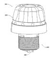
图2D为图1A-1C圆筒锁的外部透视图。Figure 2D is an external perspective view of the cylinder lock of Figures 1A-1C.
图3A和3B为依据本发明实施方式的隔间锁(compartment lock)处于锁定状态(图3A)以及处于开启状态(图3B)的截面视图。3A and 3B are cross-sectional views of a compartment lock in a locked state (FIG. 3A) and in an unlocked state (FIG. 3B) in accordance with an embodiment of the present invention.
图3C展示了通过图3A线III-III的截面。Fig. 3C shows a section through line III-III of Fig. 3A.
特定实施方式详述Detailed Description of Specific Embodiments
在下面的描述中,将参照展示在附图中的一些特定实施方式说明本发明。如应理解的,该特定的描述是说明性的而非限制性的。In the following description, the invention will be explained with reference to some specific embodiments which are illustrated in the accompanying drawings. As should be understood, this specific description is illustrative rather than restrictive.
首先参照图1A-1E,其展示了依据本发明实施方式的门圆筒锁。Reference is first made to FIGS. 1A-1E , which illustrate a door cylinder lock according to an embodiment of the present invention.
图1A-1C为展示了处于三种操作状态的锁的纵向截面:锁定状态(图1A)、中间状态(图1B)以及开启状态(图1C)。展示于图1A-1C中的锁100具有容纳在门104内的外壳102,并具有在门外部的第一转动把手组件106和在门内部的第二转动把手组件108。Figures 1A-1C are longitudinal sections illustrating the lock in three states of operation: locked state (Fig. 1A), intermediate state (Fig. 1B) and unlocked state (Fig. 1C). The
电磁锁100包括双稳态闩锁螺线管驱动机构,其中该双稳态闩锁螺线管驱动机构可操作来使锁在不同状态之间切换,并且包括带有柱塞112的螺线管110,柱塞112与第一推进弹簧114相关联,并且可在图1A所示的螺线管的缩回状态以及图1B和图1C所示的延伸状态之间轴向地位移。柱塞112具有横向伸出的延伸部分113,其目的将在下文进一步描述。弹簧114对柱塞施加偏置力,以将柱塞从缩回状态位移到延伸状态。
该锁包括锁定组件,该锁定组件可从图1E最佳地见到,并且包括锁致动单元,该锁致动单元包括远端锁致动元件120和近端锁致动元件122(关于螺线管组件)。致动元件122包括槽口(notch)124,该槽口124容纳在转动筒128的凹槽126内,并且该槽口124还适合于与转动凸轮130啮合,于是这样的啮合使筒128转动地连接到凸轮130。元件122具有圆柱形主体123,该圆柱形主体123配合在插入件128内,并且在箭头134所示的方向由第三推进弹簧136轴向地偏置。The lock includes a locking assembly, best seen in FIG. conduit assembly). Actuating
该锁定组件还包括由近端元件138和远端元件140形成的辅助推进单元。元件138配合在插入件144的圆柱形腔142内,并且具有穿过开口148伸出到把手组件108内的近端部分146。The locking assembly also includes an auxiliary advancement unit formed by a
元件140和元件120以最佳地见于图1D的方式彼此啮合。元件120和140中的每个分别具有钩部分121和141,钩部分121和141对称地相同,并因此适合于以所示的方式彼此啮合,由此避免它们彼此分离。然而,如可理解的,此种啮合允许两个元件120、140中的一个向另一个移动。
钩部分121和141的直径比元件120和140的主体的直径小,由此界定了容纳第二推进弹簧150的圆柱形圆周凹槽。第二推进弹簧偏置两个元件使其彼此离开。The diameter of the
如可以进一步在图1E特定地见到的,插入件128与球轴承160配合,以允许插入件128在外壳102的圆柱形腔162内不受阻碍地转动。插入件128和144分别具有环形凹槽129和145。分别容纳在孔166和167内的销164和165与所述环形凹槽129和145啮合,以将插入件128固定在腔162内以及将插入件144固定在腔163内。As can be seen further in particular in FIG. 1E , insert 128 cooperates with
插入件144与啮合元件170配合,该啮合元件170在插入件144和转动凸轮130之间提供固定的转动啮合。The
插入件128具有与把手106中的凹槽配合并且通过螺钉173固定的轴向伸出元件172。插入件144具有后部部分176,把手组件108配合到后部部分176并且通过螺钉178固定。The
把手组件108还包括电池以及本身为已知的通常种类的电控制电路,比如在美国专利No.6,865,916中描述的,其内容通过引用并入本文。The
在如图1A中所示的圆筒锁的锁定状态中,第一推进弹簧114被压缩,第二推进弹簧150相对放松且第三推进弹簧136也是如此。在柱塞由于发送到双稳态闩锁螺线管110的近似的电命令(approximate electriccommand)而轴向位移后,延伸部分113引起元件138和140向元件120轴向位移,从而引起第二推进弹簧150压缩到如图1B中见到的状态。在图1C中见到的随后步骤中,储存在第二推进弹簧150中的延伸能量引起第二弹簧150使元件120和122在与已位移的柱塞112相同的轴向方向上轴向位移,并且因此,初始地处于与转动凸轮130转动地分离的状态的槽口124进入转动啮合,从而在把手组件106和转动凸轮130之间产生转动连接,从而允许从外面打开门。In the locked state of the cylinder lock as shown in FIG. 1A , the
该锁控制机构一般被编程为在确定的时间段例如5-10秒后自动锁定。可选择地,这可以通过特定的开启用户施加的手动命令实现。在适当的电信号传到螺线管110时,柱塞112在相反方向从图1C所示的其延伸状态轴向移动到图1A所示的其缩回状态。在此状态中,在锁处于图1C状态时被压缩的第三推进弹簧136可以将包括元件124和120的锁致动单元轴向延伸移动到图1A中所见的锁定状态。The lock control mechanism is typically programmed to automatically lock after a determined period of time, eg 5-10 seconds. Alternatively, this can be accomplished by a specific activation user-applied manual command. When an appropriate electrical signal is delivered to the
插入件128和转动凸轮130之间的转动啮合取决于精确的转动对准;第二推进弹簧150被压缩的中间状态允许其储存位移能量,直到达到适当的转动对准,然后,锁可转换到其锁定状态。The rotational engagement between the
依据本发明的实施方式,推进弹簧114、150和136的相对强度选定为使得在没有任何磁力时,未压缩的推进弹簧114的力比处于其压缩状态的推进弹簧150的力大。处于其未压缩状态的推进弹簧150的强度比处于其压缩状态的推进弹簧136的强度大。In accordance with an embodiment of the present invention, the relative strengths of push springs 114, 150 and 136 are selected such that in the absence of any magnetic force, the force of
处于锁的锁定状态(图2A)、中间状态(图2B)以及开启状态(图2C)的依据另一个实施方式的转动锁200参见图2A-2C。圆筒锁的外部透视图可参见图2D。See FIGS. 2A-2C for a
圆筒锁200具有外壳202和转动把手组件204。把手组件204形成在外壳202内转动的一般标示为206的锁转动组件的一部分。The
把手组件204包括电池208、电子电路板210以及锁控制机构212。The
闩锁螺线管214容纳在锁内,并且包括外壳216、线圈218和固定的磁体220,外壳216、线圈218和固定的磁体220全部围绕圆柱形腔222布置,该圆柱形腔222容纳带有横向伸出的头部226的圆柱形柱塞224。该柱塞与第一推进弹簧228相关联。螺线管一般为美国专利No.6,865,916中公开的类型的双稳态螺线管。闩锁螺线管214在稳定状态之间切换,稳定状态包括如可参见图2A中的柱塞的第一缩回状态和如可参见图2B和图2C的柱塞延伸的第二稳定状态。状态之间的切换通过由包括在板210内的电子机构发出的适当的电信号进行。The
转动组件206包含锁定组件,而锁定组件包括容纳在空间232内的锁致动构件230以及具有容纳在凹槽238内的环形肩部236的辅助致动构件234。构件230和234可以在分别由空间232和凹槽238界定的路径中轴向位移。
第二推进弹簧240布置在构件230和234之间,第二推进弹簧240产生偏置力以迫使这两个构件彼此远离。构件230和234中的每个分别具有对这两个构件提供啮合的齿部分231和235,以避免它们彼此轴向分离,并且这种设置允许这两个构件进行彼此相向的相对轴向位移。A
第三推进弹簧250部分地容纳在圆柱形腔252内或推进元件254内,并且其端部搁在安装到外壳的基座元件254上。因此,第三推进弹簧250提供轴向偏置力,以在对应于柱塞从其缩回状态到其延伸状态的轴向位移的第一轴向方向抵抗构件230的轴向位移。A
构件230具有适合于转动凸轮264的齿表面262的齿表面260,因此,转动组件206的啮合转动引起转动凸轮264转动。转动凸轮264与图2D中见到的元件266啮合,元件266随后可以与门的锁定插销啮合。The
在发出激活电信号时,响应于来自控制机构212的致动信号,螺线管214被激活以将柱塞224从其在图2A中见到的在第一轴向方向的缩回状态位移到图2B中见到的缩回状态。此位移也引起构件234的对应的位移,从而引起第二弹簧240压缩,这进而引起锁致动构件230上的轴向偏置力,该轴向偏置力引起锁致动构件230逆着第三推进弹簧250的偏置力轴向位移。该位移继续,直到齿260压靠转动凸轮264的齿262。在转动组件转动时,齿260和262变得与齿262和260之间的对应的凹槽对准,由此,构件230变成完全轴向位移到图2C中见到的状态。在此状态中,转动把手组件206转动地连接到处于锁的开启状态的转动凸轮264,在锁的开启状态,把手的转动可以打开门,从而允许进入。Upon issuance of an activation electrical signal, in response to an actuation signal from the
与上面描述的实施方式的情况类似,该机构一般设计成使得在界定的时间段比如5-10秒后,相反的致动信号引起柱塞在相反的轴向方向从其延伸状态位移到其缩回状态,于是第三推进弹簧250的偏置力可以引起由构件230、第二推进弹簧240和构件234组成的整个锁定组件在所述相反的轴向方向轴向位移到图2A中见到的锁定状态。Similar to the case of the embodiments described above, the mechanism is generally designed such that after a defined period of time, such as 5-10 seconds, an opposite actuation signal causes the plunger to be displaced in the opposite axial direction from its extended state to its retracted state. return state, so the biasing force of the
依据本发明的实施方式,推进弹簧228、240和250的相对强度选定为使得在没有任何磁力时,未压缩的推进弹簧228的力比处于其未压缩状态的推进弹簧240的力大。处于其未压缩状态的推进弹簧240的强度比处于其压缩状态的推进弹簧250的强度大。In accordance with an embodiment of the present invention, the relative strengths of push springs 228, 240 and 250 are selected such that in the absence of any magnetic force, the force of
现参照关于依据本发明实施方式的隔间锁的图3A-3C。图3A和3B为在一个平面上的处于两种不同状态-锁定状态(图3A)和开启状态(图3B)的截面图,而图3C为沿图3A线III-III穿过垂直于图3A的平面的截面,图3C也展示了处于其锁定状态的锁。Reference is now made to Figures 3A-3C for a compartment lock according to an embodiment of the present invention. 3A and 3B are cross-sectional views in two different states-locked state (Fig. 3A) and unlocked state (Fig. 3B) on one plane, and Fig. 3C is along Fig. 3A line III-III passing through perpendicular to Fig. 3A A cross-section of the plane of FIG. 3C also shows the lock in its locked state.
隔间锁300具有容纳双稳态闩锁螺线管304的外壳302以及一般标示为306的锁定机构。该螺线管304包括与第一推进弹簧310相关联的柱塞308。柱塞310具有头部312,该头部312支撑在辅助致动构件316的肩部314上。The
一般标示为318的第二推进装置包括具有底部322和窄直径的延伸杆324的柱塞构件320,该柱塞构件320使用围绕杆324安装的第二螺旋弹簧326安装在辅助致动构件316的圆柱形孔内,从而以相反的轴向方向推进柱塞320以及辅助致动构件316。A second propulsion means, generally indicated at 318, includes a
第二柱塞320的底部322支撑在具有通孔332的锁致动构件330上。The
一般标示为340的第三推进装置包括第三柱塞342,而该第三柱塞342具有靠压在外壳上的底部344、中间稍窄的部分346和配合在致动构件330的孔350内的杆348。该第三推进装置还包括第三推进弹簧352,该第三推进弹簧352的一端支撑在形成在中间部分346和底部344之间的肩部上,而其另一端靠压在围绕孔350的开口界定的肩部上。A third propulsion means, generally indicated at 340, includes a
图3A和3C中的锁被展示为处于其锁定状态。当柱塞在第一方向从图3A和3C所示的缩回状态位移到图3B所示的延伸状态时,辅助致动构件316逆着第二螺旋弹簧326的偏置力位移。储存在第二推进构件326内的物理能促使第二柱塞320位移,从而将锁致动构件330位移到图3A所示的位置。在此位置,处于图3A所示的锁定状态的锁定闩360被锁定在适当位置,该锁定闩360可以在处于图3A所示的开启状态时在由孔332界定的路径内位移。The lock in Figures 3A and 3C is shown in its locked state. The
一旦处于图3B的开启状态,处于锁定状态的转动凸轮362就阻碍撞针(未示出)横向位移,转动凸轮可以转动,因此使闩360在箭头370的方向横向位移,箭头370的方向逆着偏置装置(未示出)的偏置力。当撞针被带回到位时,它引起转动凸轮362转回到图3A所示的位置,于是闩360由于受到与它相关的推进装置(未示出)施加的力而返回到位。Once in the open state of FIG. 3B , the rotating
锁致动构件330进入图3B开启状态的位移逆着第三推进弹簧352的偏置力。一旦闩360返回到其锁定状态并且柱塞返回到其缩回状态,那么第三推进弹簧就可以引起包括锁致动构件330、第二偏置装置318和辅助致动构件316的锁定组件进入其锁定状态中的原始位置。Displacement of the
依据本发明的实施方式,推进弹簧310、326和352的相对强度选定为使得在没有任何磁力时,未压缩弹簧310的力比处于其压缩状态的推进弹簧326的力大。处于其未压缩状态的推进弹簧326的强度比处于其压缩状态的推进弹簧352的强度大。In accordance with an embodiment of the present invention, the relative strengths of the push springs 310, 326 and 352 are selected such that in the absence of any magnetic force, the force of the
虽然上文参照多个实施方式描述了本发明,但对于本领域技术人员来说很显然,本发明不限制于这些实施方式,并且在本发明的范围内可以做出很多改变和修改。因此,本发明的范围仅由所附权利要求界定。Although the present invention has been described above with reference to several embodiments, it will be apparent to those skilled in the art that the present invention is not limited to these embodiments and that many changes and modifications can be made within the scope of the present invention. Accordingly, the scope of the invention is to be limited only by the appended claims.
Claims (16)
Applications Claiming Priority (3)
| Application Number | Priority Date | Filing Date | Title |
|---|---|---|---|
| US90010107P | 2007-02-08 | 2007-02-08 | |
| US60/900,101 | 2007-02-08 | ||
| PCT/IL2008/000160 WO2008096355A1 (en) | 2007-02-08 | 2008-02-06 | Solenoid-operated electromechanical lock |
Publications (2)
| Publication Number | Publication Date |
|---|---|
| CN101605955A CN101605955A (en) | 2009-12-16 |
| CN101605955B true CN101605955B (en) | 2013-07-10 |
Family
ID=39466749
Family Applications (1)
| Application Number | Title | Priority Date | Filing Date |
|---|---|---|---|
| CN2008800044341A Expired - Fee Related CN101605955B (en) | 2007-02-08 | 2008-02-06 | Solenoid-operated electromechanical lock |
Country Status (6)
| Country | Link |
|---|---|
| US (1) | US8375753B2 (en) |
| EP (2) | EP2570574B1 (en) |
| CN (1) | CN101605955B (en) |
| ES (1) | ES2435193T3 (en) |
| PL (1) | PL2115250T3 (en) |
| WO (1) | WO2008096355A1 (en) |
Families Citing this family (31)
| Publication number | Priority date | Publication date | Assignee | Title |
|---|---|---|---|---|
| BRPI0619822A2 (en) * | 2005-12-13 | 2011-10-18 | Yebo Tech Proprietary Ltd | electromechanical locking system |
| PL2126259T3 (en) * | 2007-02-21 | 2016-05-31 | Assa Abloy Ab | Lock device |
| CA2770128A1 (en) * | 2009-08-03 | 2011-02-10 | Combi Lock | Lock assembly |
| EP2529069A1 (en) * | 2010-01-25 | 2012-12-05 | Knock N'lock Ltd. | Door cylinder lock |
| EP2365475B1 (en) * | 2010-03-12 | 2013-05-08 | DESI Alarm ve Güvenlik Sistemleri Sanayi ve Ticaret Ltd. Sti. | Electrical cylinder lock |
| US20110225890A1 (en) * | 2010-03-17 | 2011-09-22 | Mark Greenwood | Gate with foot-operated latching mechanism |
| DE202011106208U1 (en) * | 2010-10-01 | 2012-01-12 | Burg-Wächter Kg | Lock cylinder for a lock |
| DE102011102140B4 (en) * | 2011-03-31 | 2013-08-08 | Burg-Wächter Kg | Lock cylinder for a lock |
| US20130335193A1 (en) * | 2011-11-29 | 2013-12-19 | 1556053 Alberta Ltd. | Electronic wireless lock |
| CN102733659B (en) * | 2012-07-05 | 2015-01-21 | 吴斐 | Electric knob device in lock body |
| EP2909402B2 (en) * | 2012-10-17 | 2021-12-15 | dormakaba Deutschland GmbH | System for lock actuation |
| US9487971B2 (en) * | 2013-03-15 | 2016-11-08 | Spectrum Brands, Inc. | Electro-mechanical locks with bezel turning function |
| CN103206118B (en) * | 2013-05-04 | 2016-06-15 | 深圳军安信息科技有限公司 | A kind of electric locking device |
| WO2014209217A1 (en) * | 2013-06-28 | 2014-12-31 | Phoniro Ab | An electronic door lock transmission |
| US9340998B2 (en) | 2014-02-25 | 2016-05-17 | Schlage Lock Company Llc | Electronic lock with movable in-line locking lug |
| IL232618B (en) * | 2014-05-14 | 2018-05-31 | Knock Nlock Ltd | Telescopic lock |
| HK1248385B (en) * | 2015-07-06 | 2020-05-22 | Acsys Holdings Limited | Lock for providing redundant channels of access |
| EP3118977B1 (en) * | 2015-07-13 | 2019-06-26 | iLOQ Oy | Electromechanical lock utilizing magnetic field forces |
| ES2627477B1 (en) * | 2015-12-28 | 2018-05-08 | Electrobolt Sistemas De Seguridad S.L. | Electromagnetic remote operated locking device |
| TWI745456B (en) | 2016-10-19 | 2021-11-11 | 美商貝斯特艾瑟斯解決方案股份有限公司 | Electromechanical core apparatus, system, and methods of operating an electromechanical core apparatus |
| AU2018247582B2 (en) * | 2017-04-05 | 2023-11-09 | Dormakaba Canada Inc. | Locking system for door, and extendible wire conduit therefore |
| US10344501B2 (en) * | 2017-08-07 | 2019-07-09 | Pamex Inc. | Electronic deadbolt lock |
| WO2019051337A1 (en) | 2017-09-08 | 2019-03-14 | Dormakaba Usa Inc. | Electro-mechanical lock core |
| CN107956327B (en) * | 2017-10-25 | 2023-04-07 | 浙江浦江梅花锁业集团有限公司 | Lock core |
| CN112752891B (en) | 2018-04-13 | 2022-08-05 | 多玛卡巴美国公司 | Electromechanical lock cylinder |
| US11466473B2 (en) | 2018-04-13 | 2022-10-11 | Dormakaba Usa Inc | Electro-mechanical lock core |
| CN108561019B (en) * | 2018-06-29 | 2024-04-12 | 云南酷联科技有限公司 | Lock clutch and control device thereof |
| IT201800010405A1 (en) * | 2018-11-16 | 2020-05-16 | Omec Serrature S P A | CYLINDER FOR DRIVE MECHANISMS |
| SE544858C2 (en) * | 2020-12-22 | 2022-12-13 | Zyax Ab | Locking device with a plunger, a driver and a transmission construction with a central ball and two outer balls and cavities |
| US11961343B2 (en) | 2021-04-13 | 2024-04-16 | D & D Design and Manufacturing, Inc. | Lock |
| NL2028758B1 (en) * | 2021-07-16 | 2023-01-23 | M & C Protect B V | Cylinder lock assembly |
Citations (6)
| Publication number | Priority date | Publication date | Assignee | Title |
|---|---|---|---|---|
| US5307656A (en) * | 1990-12-17 | 1994-05-03 | La Gard, Inc. | High security electronic dial combination lock |
| US5339662A (en) * | 1991-10-11 | 1994-08-23 | Ilco Unican, Inc. | Door locking system |
| DE29703758U1 (en) * | 1996-12-20 | 1997-06-12 | Ginder, Klaus, 82041 Oberhaching | Locking device for a locking system |
| EP0999328A1 (en) * | 1998-11-05 | 2000-05-10 | Simons & Voss Identifikationssysteme GmbH | Cylinder lock |
| CN2687248Y (en) * | 2004-04-09 | 2005-03-23 | 上海欧一安保器材有限公司 | Improved electromagnetic lock |
| CN1685125A (en) * | 2002-08-28 | 2005-10-19 | 伊兰·戈德曼 | door cylinder lock |
Family Cites Families (18)
| Publication number | Priority date | Publication date | Assignee | Title |
|---|---|---|---|---|
| CH669425A5 (en) * | 1985-06-12 | 1989-03-15 | Bauer Kaba Ag | |
| CH668451A5 (en) * | 1985-10-24 | 1988-12-30 | Bauer Kaba Ag | DEVICE FOR ELECTROMAGNETIC LOCKING ON A LOCKING CYLINDER FOR A MECHANICAL / ELECTRONIC LOCKING SYSTEM. |
| DE3713653A1 (en) * | 1987-04-21 | 1988-11-17 | Zeiss Ikon Ag | DOUBLE LOCKING CYLINDER |
| US5216909A (en) * | 1992-04-01 | 1993-06-08 | Armoogam Michael A | Electro-mechanical locking mechanism |
| DE19608953A1 (en) * | 1996-03-08 | 1997-09-11 | Harting Kgaa | Bistable small magnet |
| FR2749875B1 (en) | 1996-06-17 | 1999-10-08 | Dawalibi Nofal | ELECTRONIC LOCKING DEVICE |
| IL120957A0 (en) | 1997-03-07 | 1997-09-30 | Goldman Ilan | Code activated system |
| DE19727422C1 (en) * | 1997-06-27 | 1998-06-25 | Meyers Pierre | Coupling system for electronic lock |
| FR2779168B1 (en) | 1998-05-27 | 2001-01-26 | Euronetics France | ELECTRONIC LOCK WITH MECHANICAL CLUTCH |
| GB2341202B (en) * | 1998-09-02 | 2000-07-19 | Shyang Feng Electric & Machine | Electronic lock |
| DE19913644C2 (en) * | 1999-03-25 | 2001-02-01 | Sphinx Elektronik Gmbh | Lock, especially furniture lock |
| US6286347B1 (en) * | 1999-08-09 | 2001-09-11 | Harrow Products, Inc. | Clutch mechanism with moveable injector retainer wall for door lock system |
| US6474122B2 (en) | 2000-01-25 | 2002-11-05 | Videx, Inc. | Electronic locking system |
| DE60110103T2 (en) * | 2000-08-22 | 2006-06-01 | Kowalczyk, Piotr Leonard | LOCK |
| US6581423B2 (en) * | 2001-11-01 | 2003-06-24 | Ching-Tien Lin | Door lock |
| US6677844B1 (en) * | 2002-10-21 | 2004-01-13 | Adams Rite Aerospace, Inc. | Quick-return electro-mechanical actuator |
| IL154788A (en) | 2003-03-06 | 2010-12-30 | Goldman Ilan | Electronic locking mechanism and lock containing it |
| US7784315B2 (en) * | 2007-07-20 | 2010-08-31 | Ping-Jan Yang | Locking device for truck |
-
2008
- 2008-02-06 PL PL08710160T patent/PL2115250T3/en unknown
- 2008-02-06 WO PCT/IL2008/000160 patent/WO2008096355A1/en not_active Ceased
- 2008-02-06 CN CN2008800044341A patent/CN101605955B/en not_active Expired - Fee Related
- 2008-02-06 ES ES08710160T patent/ES2435193T3/en active Active
- 2008-02-06 EP EP20120195991 patent/EP2570574B1/en not_active Not-in-force
- 2008-02-06 EP EP20080710160 patent/EP2115250B1/en not_active Not-in-force
- 2008-02-06 US US12/449,356 patent/US8375753B2/en not_active Expired - Fee Related
Patent Citations (6)
| Publication number | Priority date | Publication date | Assignee | Title |
|---|---|---|---|---|
| US5307656A (en) * | 1990-12-17 | 1994-05-03 | La Gard, Inc. | High security electronic dial combination lock |
| US5339662A (en) * | 1991-10-11 | 1994-08-23 | Ilco Unican, Inc. | Door locking system |
| DE29703758U1 (en) * | 1996-12-20 | 1997-06-12 | Ginder, Klaus, 82041 Oberhaching | Locking device for a locking system |
| EP0999328A1 (en) * | 1998-11-05 | 2000-05-10 | Simons & Voss Identifikationssysteme GmbH | Cylinder lock |
| CN1685125A (en) * | 2002-08-28 | 2005-10-19 | 伊兰·戈德曼 | door cylinder lock |
| CN2687248Y (en) * | 2004-04-09 | 2005-03-23 | 上海欧一安保器材有限公司 | Improved electromagnetic lock |
Also Published As
| Publication number | Publication date |
|---|---|
| EP2570574B1 (en) | 2014-09-17 |
| PL2115250T3 (en) | 2014-02-28 |
| EP2570574A1 (en) | 2013-03-20 |
| US8375753B2 (en) | 2013-02-19 |
| ES2435193T3 (en) | 2013-12-16 |
| EP2115250B1 (en) | 2013-08-14 |
| EP2115250A1 (en) | 2009-11-11 |
| CN101605955A (en) | 2009-12-16 |
| WO2008096355A1 (en) | 2008-08-14 |
| US20090308117A1 (en) | 2009-12-17 |
Similar Documents
| Publication | Publication Date | Title |
|---|---|---|
| CN101605955B (en) | Solenoid-operated electromechanical lock | |
| US6463773B1 (en) | Electronic latch apparatus and method | |
| US8001818B2 (en) | Clutch mechanism couplable to door locks with locking bolt operated by handles or knobs | |
| US4736970A (en) | Electrically controlled door lock | |
| US5953942A (en) | Catch mechanism for locks | |
| RU2337220C2 (en) | Cylinder door lock | |
| CA2710063C (en) | Handle device | |
| JP2006511738A (en) | Locking device | |
| CA2788958C (en) | Apparatus for automatically returning a lock to a desired orientation | |
| CA2492841A1 (en) | A self-latching magnetic latching device | |
| CA3112565C (en) | Push through latch | |
| WO2008029391A2 (en) | Electronic cylinder internal key apparatus and method | |
| US11525279B2 (en) | Handle device | |
| RU2441968C2 (en) | Electronic lock with passive lockdown tool | |
| RU2783155C1 (en) | Electromechanical locking device | |
| WO2024005661A1 (en) | Electromechanical locking device | |
| JP2003307058A (en) | Card lock device | |
| EA044127B1 (en) | ELECTROMECHANICAL LOCKING DEVICE | |
| JP2022020904A (en) | Electric lock | |
| RU2129200C1 (en) | Coding magneto-mechanical lock | |
| CN112955618A (en) | Lock head for driving mechanism | |
| HK1094239A1 (en) | Electronic locking mechanism and lock containing it | |
| HK1094239B (en) | Electronic locking mechanism and lock containing it | |
| HK1084430B (en) | Door cylinder lock |
Legal Events
| Date | Code | Title | Description |
|---|---|---|---|
| C06 | Publication | ||
| PB01 | Publication | ||
| C10 | Entry into substantive examination | ||
| SE01 | Entry into force of request for substantive examination | ||
| C14 | Grant of patent or utility model | ||
| GR01 | Patent grant | ||
| CF01 | Termination of patent right due to non-payment of annual fee |
Granted publication date: 20130710 Termination date: 20160206 |
|
| CF01 | Termination of patent right due to non-payment of annual fee |