CN101595546A - Overheat protection device, use and circuit - Google Patents
Overheat protection device, use and circuit Download PDFInfo
- Publication number
- CN101595546A CN101595546A CNA2006800283061A CN200680028306A CN101595546A CN 101595546 A CN101595546 A CN 101595546A CN A2006800283061 A CNA2006800283061 A CN A2006800283061A CN 200680028306 A CN200680028306 A CN 200680028306A CN 101595546 A CN101595546 A CN 101595546A
- Authority
- CN
- China
- Prior art keywords
- memory alloy
- thermal protection
- shape memory
- circuit
- protection device
- Prior art date
- Legal status (The legal status is an assumption and is not a legal conclusion. Google has not performed a legal analysis and makes no representation as to the accuracy of the status listed.)
- Pending
Links
Images


Classifications
-
- H—ELECTRICITY
- H05—ELECTRIC TECHNIQUES NOT OTHERWISE PROVIDED FOR
- H05K—PRINTED CIRCUITS; CASINGS OR CONSTRUCTIONAL DETAILS OF ELECTRIC APPARATUS; MANUFACTURE OF ASSEMBLAGES OF ELECTRICAL COMPONENTS
- H05K1/00—Printed circuits
- H05K1/02—Details
- H05K1/0201—Thermal arrangements, e.g. for cooling, heating or preventing overheating
-
- H—ELECTRICITY
- H05—ELECTRIC TECHNIQUES NOT OTHERWISE PROVIDED FOR
- H05K—PRINTED CIRCUITS; CASINGS OR CONSTRUCTIONAL DETAILS OF ELECTRIC APPARATUS; MANUFACTURE OF ASSEMBLAGES OF ELECTRICAL COMPONENTS
- H05K2201/00—Indexing scheme relating to printed circuits covered by H05K1/00
- H05K2201/03—Conductive materials
- H05K2201/0302—Properties and characteristics in general
- H05K2201/0308—Shape memory alloy [SMA]
-
- H—ELECTRICITY
- H05—ELECTRIC TECHNIQUES NOT OTHERWISE PROVIDED FOR
- H05K—PRINTED CIRCUITS; CASINGS OR CONSTRUCTIONAL DETAILS OF ELECTRIC APPARATUS; MANUFACTURE OF ASSEMBLAGES OF ELECTRICAL COMPONENTS
- H05K2203/00—Indexing scheme relating to apparatus or processes for manufacturing printed circuits covered by H05K3/00
- H05K2203/17—Post-manufacturing processes
- H05K2203/175—Configurations of connections suitable for easy deletion, e.g. modifiable circuits or temporary conductors for electroplating; Processes for deleting connections
Landscapes
- Engineering & Computer Science (AREA)
- Microelectronics & Electronic Packaging (AREA)
- Fuses (AREA)
- Thermally Actuated Switches (AREA)
- Power Conversion In General (AREA)
- Measuring Temperature Or Quantity Of Heat (AREA)
Abstract
Description
背景background
本申请总体上涉及热保护,特别涉及过热保护装置。This application relates generally to thermal protection, and more particularly to overheating protection devices.
使用温度敏感形状记忆合金提供过热保护是众所周知的。形状记忆合金制成的开关接触臂在常温情况下具有变形的形状,并在温度升高的情况下变为复原形状。这些形状的变化提供不同的接触臂位置,其可用于断开或闭合电路。The use of temperature sensitive shape memory alloys to provide overheating protection is well known. The switch contact arm made of shape memory alloy has a deformed shape at normal temperature and changes to a restored shape when the temperature rises. These shape variations provide different contact arm positions, which can be used to open or close a circuit.
形状记忆合金开关已被组合在电池中以在电池过热时断开电池电路。美国专利6,294,977公开了这样的装置,其全部内容通过引用组合于此。所述装置在一对导电部件之间夹有由形状记忆合金制成的接触件。该接触件具有接触臂,其通过在常温情况下的变形形状和温度升高情况下的复原形状之间变化而断开导电外部件之间的电流路径。接触臂当其在常温情况下处于变形形状时与两个导电部件均接合,当在温度升高情况下处于复原形状时与部件之一的接合移开。Shape memory alloy switches have been incorporated into batteries to disconnect the battery circuit if the battery overheats. Such a device is disclosed in US Patent 6,294,977, the entire contents of which are hereby incorporated by reference. The device sandwiches a contact made of a shape memory alloy between a pair of conductive members. The contact has a contact arm that breaks a current path between the conductive outer parts by changing between a deformed shape at normal temperature and a restored shape at elevated temperature. The contact arm engages both conductive parts when it is in its deformed shape at normal temperature and disengages from one of the parts when it is in its restored shape at elevated temperature.
在上述专利公开了一种可能的形状记忆合金开关的同时,需要更简单及更广泛适用的形状记忆热开关。While the aforementioned patent discloses a possible shape memory alloy switch, there is a need for a simpler and more widely applicable shape memory thermal switch.
发明内容 Contents of the invention
下面讨论的本发明例子提供过热保护。所述例子包括过热保护装置、衬底如印刷电路板上的过热应用、及过热保护电路如与熔断器或加热器结合的过热保护。不同的例子包括形状记忆合金件的使用,其或能断开与导体的电接触(断开电路)或能与导体电接触(闭合电路)。在断开第一电路的基础上,所述形状记忆合金件可移动以接触另一导体并完成第二电路。形状记忆合金件可闭合电路,其与装有熔断器的负载并联,以在例如电装置如移动电话或电池内出现过热条件时提供使熔断器断开的短路路径。或者,形状记忆合金件可与加热器并联,其在过流条件时通电从而触发所述形状记忆合金件断开电路。The examples of the invention discussed below provide overheating protection. Examples include thermal protection devices, thermal application on substrates such as printed circuit boards, and thermal protection circuits such as thermal protection in combination with fuses or heaters. Different examples include the use of shape memory alloy pieces that either break electrical contact with the conductor (open circuit) or make electrical contact with the conductor (close circuit). Upon breaking the first circuit, the shape memory alloy piece is movable to contact another conductor and complete the second circuit. The shape memory alloy piece can close an electric circuit in parallel with a fused load to provide a short circuit path for opening the fuse in the event of an overheating condition, for example, within an electrical device such as a mobile phone or battery. Alternatively, the shape memory alloy piece may be connected in parallel with a heater which is energized during an overcurrent condition to trigger the shape memory alloy piece to break the circuit.
具体地,在第一主要实施例中,提供了热保护装置,其包括:(i)扁平绝缘衬底;(ii)位于绝缘衬底一侧上的第一和第二导体;及(iii)形状记忆合金件,其第一端固定到第一导体,第二端最低限度地搭接在第二导体上。在此,当形状记忆合金件达到其激活温度时,其至少部分恢复到预设形状,使得形状记忆合金件的第二端脱离第二导体并断开电路。Specifically, in a first main embodiment, there is provided a thermal protection device comprising: (i) a flat insulating substrate; (ii) first and second conductors on one side of the insulating substrate; and (iii) A shape memory alloy piece having a first end fixed to the first conductor and a second end minimally overlapping the second conductor. Here, when the shape memory alloy piece reaches its activation temperature, it at least partially returns to the preset shape, so that the second end of the shape memory alloy piece breaks away from the second conductor and breaks the circuit.
衬底可由一种或一种以上材料制成,如FR-4材料、纺织或无纺玻璃、PTFE玻璃、微纤维玻璃、陶瓷、热固性塑料、聚酰亚胺、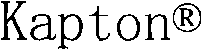
所述电路可具有多种变化。在一例子中,所述电路置放在印刷电路板上。电路可包括许多不同类型的电组件,如熔断器、加热元件、电压源及负载。There are many variations of the described circuit. In one example, the circuitry is placed on a printed circuit board. Circuits can include many different types of electrical components such as fuses, heating elements, voltage sources and loads.
通常,形状记忆合金被退火以形成其预设形状,这可以是线圈型形状、扭折形状或线性形状。在一实施例中,形状记忆合金件由镍-钛合金制成。形状记忆合金件也可被涂覆导电材料以降低其电阻。形状记忆合金件可被设定为具有任何所希望的激活温度如约60℃到约100℃。Typically, shape memory alloys are annealed to form their predetermined shape, which may be a coiled shape, a kink shape, or a linear shape. In one embodiment, the shape memory alloy piece is made of nickel-titanium alloy. Shape memory alloy pieces can also be coated with a conductive material to reduce their electrical resistance. The shape memory alloy piece can be configured to have any desired activation temperature, such as about 60°C to about 100°C.
在该第一主要实施例中,被断开的电路可以是第一电路,且其包括第三电极,形状记忆合金件的第二端在脱离第二导体并断开第一电路之后接触第三电极并闭合第二电路。第一和第二电路中的任一电路可具有上述的多种变化。In this first main embodiment, the circuit to be disconnected may be a first circuit, and it includes a third electrode, and the second end of the shape memory alloy member contacts the third electrode after breaking away from the second conductor and breaking the first circuit. electrode and close the second circuit. Either of the first and second circuits may have various variations as described above.
在第二主要实施例中,提供了热保护装置,其包括:(i)扁平绝缘衬底;(ii)位于绝缘衬底一侧上的第一和第二导体;及(iii)形状记忆合金件,其第一端固定到第一导体。在此,当形状记忆合金件达到其激活温度时,其至少实质上恢复到预设形状,使得形状记忆合金件的第二端接触第二导体并完成电路。In a second main embodiment, a thermal protection device is provided comprising: (i) a flat insulating substrate; (ii) first and second conductors on one side of the insulating substrate; and (iii) a shape memory alloy A member having a first end secured to the first conductor. Here, when the shape memory alloy piece reaches its activation temperature, it at least substantially returns to the preset shape such that the second end of the shape memory alloy piece contacts the second conductor and completes the circuit.
上述衬底及电路的每一变化均可应用于该第二主要实施例。在形状记忆合金件达到其激活温度之后其第二端经材料和/或装置搭接第二导体。Every variation of the substrate and circuitry described above is applicable to this second main embodiment. After the shape memory alloy member reaches its activation temperature, its second end overlaps the second conductor via material and/or means.
总之,形状记忆合金被退火以形成其预设形状,可以是展开或伸直形状。元件可在淬火后形成以具有卷曲或扭折形状。形状记忆合金件由镍-钛合金制成,并被涂覆以导电材料和/或设为具有任何所需激活温度。In summary, shape memory alloys are annealed to form their predetermined shape, which may be an unfolded or straightened shape. Elements may be formed after quenching to have a curled or twisted shape. The shape memory alloy piece is made of a nickel-titanium alloy and is coated with a conductive material and/or set to have any desired activation temperature.
在第三主要实施例中,提供了热保护装置,其包括:(i)绝缘外壳;(ii)分别位于所述外壳的第一和第二端上的第一和第二导体;及(iii)形状记忆合金件,其第一端固定到第一导体及第二端最低限度地搭接在第二导体上。在此,当形状记忆合金件达到其激活温度时,其恢复到预设形状,使得形状记忆合金件的第二端脱离第二导体并断开电路。In a third main embodiment, there is provided a thermal protection device comprising: (i) an insulating housing; (ii) first and second conductors respectively located on first and second ends of said housing; and (iii ) a shape memory alloy member having a first end fixed to the first conductor and a second end minimally overlapping the second conductor. Here, when the shape memory alloy piece reaches its activation temperature, it returns to the preset shape, so that the second end of the shape memory alloy piece breaks away from the second conductor and breaks the circuit.
热保护装置可以通过使用下述方式进行表面安装:夹子、插销座、导电粘合剂、和/或使用第一和第二导体的足够散热进行焊接。例如,形状记忆合金件的第二端可经材料或器械进行最低限度地搭接。The thermal protection device may be surface mounted by using clips, pin sockets, conductive adhesive, and/or soldering with sufficient heat dissipation of the first and second conductors. For example, the second end of the shape memory alloy member may be minimally overlapped by material or instrumentation.
上述关于电路和元件的许多变化均可应用于该第三主要实施例。另外,所述元件的第二端可连接到接触件,其脱离第二导体并断开电路。第二导体可包括第一和第二分开的部分,所述接触件脱离第一和第二分开的部分,其中所述电路在所述两部分之间断开。Many variations of the circuits and components described above are applicable to this third main embodiment. Additionally, the second end of the element may be connected to a contact, which disengages the second conductor and breaks the circuit. The second conductor may comprise first and second separate parts from which the contact is disengaged, wherein the electrical circuit is broken between the two parts.
在第四主要实施例中,提供了热保护装置,其包括:(i)绝缘外壳;(ii)分别位于所述外壳的第一和第二端上的第一和第二导体;及(iii)形状记忆合金件,其第一端固定到第一导体及第二端固定到第二导体,沿该形状记忆合金件还具有至少一脆弱点。在此,当形状记忆合金件达到其激活温度时,其恢复到预设形状,使得形状记忆合金件在所述脆弱点至少实质上断裂并断开电路。In a fourth main embodiment, there is provided a thermal protection device comprising: (i) an insulating housing; (ii) first and second conductors respectively located on first and second ends of said housing; and (iii) ) a shape memory alloy piece having a first end fixed to the first conductor and a second end fixed to the second conductor, and having at least one weak point along the shape memory alloy piece. Here, when the shape memory alloy piece reaches its activation temperature, it returns to the preset shape, so that the shape memory alloy piece at least substantially breaks at the weak point and breaks the circuit.
上述关于电路、元件及装置的安装的许多变化均可应用于该第四主要实施例。另外,一个或多个脆弱点可至少实质上居中位于所述形状记忆合金件上,其由一个或多个穿孔形成和/或由沿形状记忆合金件的一个或多个变薄区域形成。Many of the variations described above with regard to the arrangement of circuits, components and devices can be applied to this fourth main embodiment. Additionally, one or more points of weakness may be located at least substantially centrally on the shape memory alloy piece, formed by one or more perforations and/or by one or more thinned regions along the shape memory alloy piece.
在第五主要实施例中,提供了热保护装置,其包括:(i)绝缘外壳;(ii)分别位于所述外壳的第一和第二端上的第一和第二导体;及(iii)具有第一端和第二端的形状记忆合金件。在此,当形状记忆合金件达到其激活温度时恢复到预设形状,使得形状记忆合金件的第一端和第二端完成电路,其与第一和第二导体电连通。In a fifth main embodiment, there is provided a thermal protection device comprising: (i) an insulating housing; (ii) first and second conductors respectively located on first and second ends of said housing; and (iii) ) a shape memory alloy piece having a first end and a second end. Here, the shape memory alloy piece returns to the preset shape when it reaches its activation temperature, so that the first end and the second end of the shape memory alloy piece complete an electrical circuit, which is in electrical communication with the first and second conductors.
上述关于电路、元件和装置的安装的许多变化均可应用于该第五主要实施例。另外,所述形状记忆合金件的第一端或第二端或第一及第二端可连接到接触件,所述接触件与第一和第二导体之一接触以完成电路。第一和第二导体之一可包括第一和第二分开的部分,所述接触件与第一和第二部分接触,电路通过桥接所述两部分完成。所述形状记忆合金件在初始时其第一和第二端之一还可分别连接到第一和第二导体之一,或者在初始时不与任一导体连接。Many of the variations described above with respect to the installation of circuits, components and devices can be applied to this fifth main embodiment. Additionally, the first end or the second end or the first and second ends of the shape memory alloy piece may be connected to a contact which contacts one of the first and second conductors to complete the electrical circuit. One of the first and second conductors may comprise first and second separate parts, the contact is in contact with the first and second parts, and the electrical circuit is completed by bridging the two parts. One of the first and second ends of the shape memory alloy piece may also be initially connected to one of the first and second conductors, or not be initially connected to any conductor.
在第六主要实施例中,提供了热保护装置,其包括:(i)绝缘外壳;(ii)分别位于所述外壳的第一和第二端上的第一和第二导体;(iii)具有第一端和第二端的弹簧;及(iv)使弹簧保持压缩状态使得弹簧的第一和第二端分别不与第一和第二导体接触的材料。在此,当所述材料达到激活温度时变形或熔化,使得弹簧伸直且弹簧的第一和第二端接触第一和第二导体。In a sixth main embodiment, there is provided a thermal protection device comprising: (i) an insulating housing; (ii) first and second conductors respectively located on first and second ends of said housing; (iii) a spring having a first end and a second end; and (iv) a material that maintains the spring in a compressed state such that the first and second ends of the spring are not in contact with the first and second conductors, respectively. Here, the material deforms or melts when it reaches an activation temperature such that the spring straightens and the first and second ends of the spring contact the first and second conductors.
上述关于电路和装置的安装的许多变化均可应用于该第六主要实施例。另外,所述材料可以是石蜡或低熔化温度聚合物。所述材料可构造为包住处于压缩状态的弹簧或构造为与弹簧相连置放以使弹簧保持压缩状态的插头。此外,所述弹簧可由选自下组的至少一材料制成:不锈钢、涂覆铬钒或镍的不锈钢。Many of the variations described above with respect to the installation of circuits and devices are applicable to this sixth main embodiment. Alternatively, the material may be paraffin or a low melting temperature polymer. The material may be configured to encase the spring in compression or as a plug placed in connection with the spring to maintain the spring in compression. Furthermore, the spring may be made of at least one material selected from the group consisting of stainless steel, stainless steel coated with chromium vanadium or nickel.
在第七实施例中,提供了热保护电路,其包括:(i)电压源;(ii)负载;(iii)与电压源和负载串联的熔断器;及(iv)与负载并联的热保护装置。在此,当热保护装置达到激活温度时导致短路,从而导致熔断器断开。热保护装置可包括形状记忆合金件并可常开或常闭。In a seventh embodiment, a thermal protection circuit is provided comprising: (i) a voltage source; (ii) a load; (iii) a fuse in series with the voltage source and load; and (iv) a thermal protection in parallel with the load device. Here, a short circuit is caused when the thermal protection device reaches the activation temperature, which causes the fuse to open. The thermal protection device may comprise a shape memory alloy and may be normally open or normally closed.
上面列出的实施例并非穷尽的,且绝不用于限制本发明的范围。The examples listed above are not exhaustive and are in no way intended to limit the scope of the invention.
因此,本发明的优点在于提供改进的过热保护应用、装置和电路。Accordingly, it is an advantage of the present invention to provide improved overheating protection applications, devices and circuits.
本发明的另一优点在于提供与熔断器或加热器结合的过热保护。Another advantage of the present invention is to provide overheating protection in combination with a fuse or heater.
本发明的另一优点在于提供过热保护,其(i)构成或断开电路;或(ii)断开第一电路及构成第二电路。Another advantage of the present invention is to provide overheating protection which (i) makes or breaks a circuit; or (ii) breaks a first circuit and makes a second circuit.
本发明的另一优点在于提供过热保护,其产生在过热条件时断开熔断器的短路路径。Another advantage of the present invention is to provide overheating protection that creates a short circuit path that opens the fuse in the event of an overheating condition.
本发明的另一优点在于提供与加热器并联的过热保护,其在过电压条件时接通,从而触发形状记忆合金件断开或闭合电路。Another advantage of the present invention is to provide overheat protection in parallel with the heater, which turns on during an overvoltage condition, thereby triggering the shape memory alloy piece to open or close the circuit.
本发明的另外的特征和优点将在下面本发明的具体实施方式及附图中描述并可从其明显看出。Additional features and advantages of the invention will be described in and will be apparent from the following detailed description of the invention and accompanying drawings.
附图说明 Description of drawings
图1A和1B分别为采用形状记忆合金及最低限度搭接材料或器械的应用的一个实施例在闭合和断开情形下的示意立视图。1A and 1B are schematic elevational views, respectively, of one embodiment of an application employing shape memory alloys and minimally overlapping materials or devices, in closed and open conditions.
图1C为采用形状记忆合金和最低限度搭接器械的应用的一个实施例的示意图。Figure 1C is a schematic illustration of one embodiment of an application employing shape memory alloys and minimally overlapping instruments.
图2A和2B分别为采用形状记忆合金和最低限度搭接材料或器械的应用的一个实施例的第一和第二示意平面图,所述形状记忆合金和最低限度搭接材料或器械形成多个导电路径。2A and 2B are first and second schematic plan views, respectively, of one embodiment of an application employing a shape memory alloy and minimally bonding material or device forming a plurality of electrically conductive path.
图3A和3B分别为采用形状记忆合金和最低限度搭接材料或器械的常闭装置的一实施例在闭合及断开情形下的示意截面立视图。3A and 3B are schematic cross-sectional elevation views, respectively, of an embodiment of a normally closed device employing shape memory alloys and minimally overlapping materials or devices, in closed and open conditions.
图4A和4B为采用形状记忆合金和最低限度搭接材料或器械的常闭装置的另一实施例在闭合和断开情形下的示意截面立视图。4A and 4B are schematic cross-sectional elevation views of another embodiment of a normally closed device employing a shape memory alloy and minimally overlapping material or instrument, in closed and open conditions.
图5A和5B分别为采用形状记忆合金的常闭装置的另一实施例在闭合和断开情形下的示意截面立视图。5A and 5B are schematic cross-sectional elevation views of another embodiment of a normally closed device employing a shape memory alloy in closed and open conditions, respectively.
图6A和6B分别为采用形状记忆合金的常开装置的一实施例在断开和闭合情形下的示意截面立视图。6A and 6B are schematic cross-sectional elevation views, respectively, of an embodiment of a normally open device employing a shape memory alloy in open and closed conditions.
图7A和7B分别为采用压缩弹簧及包封材料的常开装置的一实施例在断开和闭合情形下的示意截面立视图。7A and 7B are schematic cross-sectional elevation views, respectively, of an embodiment of a normally open device employing a compression spring and encapsulating material in the open and closed conditions.
图8A和8B分别为采用连接到导体的形状记忆合金的常开装置的一实施例在断开和闭合情形下的示意截面立视图,所述形状记忆合金可短接两个端子之间的间隙。8A and 8B are schematic cross-sectional elevation views, respectively, of an embodiment of a normally open device employing a shape memory alloy attached to a conductor, which can short the gap between two terminals, in the open and closed conditions. .
图9为可与过电流保护装置一起使用的热保护开关的示意电路图。Figure 9 is a schematic circuit diagram of a thermal protection switch that may be used with an overcurrent protection device.
图10A和10B分别为采用可与过电流保护装置一起使用的热保护开关的应用的一实施例在断开和闭合情形时的示意平面图。10A and 10B are schematic plan views of an embodiment of an application employing a thermally protected switch usable with an overcurrent protection device in open and closed conditions, respectively.
图11为可与加热器一起使用的热保护开关的示意电路图。Figure 11 is a schematic circuit diagram of a thermal protection switch that may be used with a heater.
具体实施方式 Detailed ways
现在参考附图特别是图1A和lB,热或过热保护装置的实施例如装置10所示。图1A所示为当不存在过热条件时装置10处于常闭位置。图1B所示为当出现过热条件时装置10处于常开位置。Referring now to the drawings and in particular to FIGS. 1A and 1B , an embodiment of a thermal or overheating protection device such as
装置10包括衬底12。衬底12可由任一或多种类型的硬或半硬材料制成,如FR-4材料、纺织或无纺玻璃、PTFE玻璃、微纤维玻璃、陶瓷、热固性塑料、聚酰亚胺、
如图所示,提供了形状记忆合金件20。形状记忆合金件20(及在此描述的每一形状记忆件)可以是任何适当的长度、截面形状及截面积。件20的长度例如可以为约0.250英寸(6.35mm)或更小。例如,平均截面长度可以为约0.0472英寸(1.18mm)或更小。例如,截面形状可以为圆形、正方形、矩形、椭圆形等。其它长度、截面积和截面形状也可用于件20。As shown, a shape
在一实施例中,件20由镍-钛合金制成。然而,也可使用其它形状记忆合金,如含铜三元合金,包括铜-锌-铝和铜-镍-铝。通过选择不同的形状记忆合金组成及通过改变热处理或淬火工艺,合金从其变形形状变为其复原形状的转变温度范围也可大大变化。在图1A和1B中,件20被冲压、切割或其它成形为图1B中所示的弯曲形状,之后,高于其奥氏体变换温度对合金进行淬火。接着,件20被冷却到其马氏体状态,其后件自身变形为图1A中所示的扁平形状。In one embodiment,
当装置10遭受马氏体变为奥氏体的变换温度时,如约60℃到约100℃,件20恢复到其如图1B中所示的复原形状。在一实施例中,装置10可复位,其中当冷却件20恢复其扁平变形形状时,在导体14和16之间重新建立电连续性。在另一实施例中,装置10不可复位(从而导致一次性装置),其中件20或保持其复原形状或稍微但不弯曲恢复其变形形状。When
可选择件20的形状记忆合金以具有大范围的变换或转变温度。转变温度选择为在或刚低于需要保护的过热条件。对于与某些电装置一起使用,转变温度可以是约60℃到约100℃,正负5℃。应意识到,宽范围的合金和变换温度可根据热开关组件的应用进行选择。The shape memory alloy of
在不同备选实施例中,件20(及在此描述的每一形状记忆件)可被涂覆或电镀以导电材料如铜、其它金属或导电聚合物以降低件20的总电阻,同时保持其形状记忆特性。件20可由单股形状记忆合金制成或具有多股辫子形或绞合形状合金材料。此外,形状合金材料的一股或多股可与导体如铜线的一股或多股绞合以降低件20的总电阻,同时保持其形状记忆特性。In various alternative embodiments, member 20 (and each shape memory member described herein) may be coated or plated with a conductive material such as copper, other metals, or conductive polymers to reduce the overall resistance of
件20经任何适当的一种或多种机械、化学或电化学固紧器械将固定端稳固地固定到导体14。例如,件20的端部可以机械方式夹到或压接到导体14上。例如,导体14可包括支承件20的固定端的座或夹子。或者或另外,件20的固定端可经导电粘合剂连到导体14。此外,件20的固定端可焊接到导体14,例如用足够的散热手焊以使所述件不能达到其激活温度。
件20的第二端最低限度地或可释放地搭接到导体16。在图1A和1B中,示出了搭接材料22。搭接材料可以是任何类型的材料,当件20尚未达到激活温度时,其使件20的第二端安全地搭接在导体16上,但在件20已达到激活温度时,其使件20的第二端能从导体16松开或移开。在一实施例中,材料22包括或是填充银(或其它导电材料)的聚合材料或导电油脂。The second end of
另外参考图1C,件20的第二端经机械器械24如导电夹子24可释放地搭接在导体16上。夹子24经焊料或类似材料26粘附到导体16上或用导体16形成。在此,当件20尚未达到激活温度时,件20的释放端被夹或压接到夹子24上。当件20已达到激活温度时,件20的释放端从夹子24松开或移开。With additional reference to FIG. 1C , the second end of
机械搭接装置也可以是第二形状记忆合金件(未示出),其在正常情况下将件20的第二端最低限度地保持在适当位置,但当达到激活温度(稍高于或低于件20的激活温度)时弯曲或弹回以使件20的第二端与导体16断开电连接。The mechanical bridging means can also be a second shape memory alloy piece (not shown) which normally holds the second end of
在上述的任何情形下,图1A的件20在其达到激活温度之前使电流能流过连接到导体14和16的电路。如图1B中所见,当件20达到激活温度时,件20的释放端脱离导体16,从而断开电路。这是常闭应用。在备选实施例中,件20被构造为常开,使得件20当达到激活温度时与导体16电接触。In any of the cases described above,
连接到导体14和16的电路(对于在此描述的任何实施例)可以是任何适当类型的电路,如下述之一:(i)提供在印刷电路板上;(ii)与熔断器电连通;(iii)与加热元件电连通;(iv)与电压源电连通;及(v)移动电话、数字音乐播放器、计算机、电池或数码相机的一部分。The circuitry connected to
装置10可直接应用于与应用装置一起使用的印刷电路板。装置10也可应用于与应用装置一起使用的较小印刷电路板(即子板)。装置10可被包或罩在装置中。The
现在参考图2A和2B,第二形状记忆合金过热装置如装置30所示。对于衬底12的任何上述实施例均可应用于装置30的衬底12。对于导体14和16的任何上述实施例均可应用于装置30的导体14-18。对于材料22的任何上述实施例(及机械变化)均可应用于装置30的材料22的施加。对于件20的任何上述实施例均可应用于装置30的件32。Referring now to FIGS. 2A and 2B , a second shape memory alloy superheating device is shown as
件32被冲压、切割或其它成形为图2B中所示的第一弯曲形状,之后,高于其奥氏体变换温度对合金进行退火。接着,件32被冷却到其马氏体状态,其后件变形为图2A中所示的第二弯曲形状。图2A中的件32在其达到激活温度之前使电流能流过连接到导体14和16的电路。如图2B中所示,当件32达到激活温度时,件32的活动端脱离导体16,从而断开电连接到接触件14和16的常闭电路。此外,件32的活动端移动并接触第三导体18,闭合或形成电连接到接触件14和18的常开电路。导体18可与任何适当的及所需的第二电路如报警电路连通。The
如图所示,导体18可包括材料22,其在件32的活动端脱离导体16之后使所述活动端保持接触第三导体18。或者,导体18包括接收件32的卷边或夹子。在一实施例中,装置30可复位,其中当冷却件32恢复到图2A中所示的形状时,在导体14和16之间重新建立电连续性。在另一实施例中,装置10不可复位(从而导致一次性装置),其中件32或保持连接到导体18的复原形状,或稍微但不完全恢复到变形形状。As shown, the
装置30可直接应用于与应用装置一起使用的印刷电路板。装置30也可应用于与应用装置一起使用的较小印刷电路板(即子板)。装置30可被包或罩在装置中。The
现在参考图3A和3B、4A和4B及5A和5B,采用形状记忆合金件的常闭装置的不同实施例如装置40、60和70所示。装置40、60和70(及在此所述的任何装置)可属于表面安装种类,并可具有分别为约3.2mm、1.6mm和0.8mm的长度、宽度和高度。在一实施例中,装置的焊点布局符合IPC标准。在将所述装置连到印刷电路板(PCB)时,需要注意所述装置的激活温度。在实施例中,所述装置经夹子、插销座、导电粘合剂、用足够散热钎焊或其它器械或方法连到PCB以保持形状记忆件的温度低于激活温度。Referring now to FIGS. 3A and 3B , 4A and 4B and 5A and 5B, various embodiments of normally closed devices employing shape memory alloy members are shown as
装置40、60和70(及在此所述的任何装置)可以是轴引线模型,并具有分别为约7.11mm和2.41mm的长度和直径。轴引线模型应经座或焊接操作期间铅的足够散热进行安装以保持形状记忆件的温度低于其激活温度。
装置40、60和70包括多个共同构件。装置40、60和70中的每一个包括绝缘外壳42。外壳42可由任何适当的电绝缘材料制成,如绝缘塑料、玻璃或陶瓷。绝缘外壳42具有高于装置40、60和70的激活温度的熔化温度。用于外壳42的适当塑料包括但不限于聚碳酸酯、聚醚醚酮或聚苯硫醚。
装置40、60和70中的每一个包括导体44和46。导体44和46可由单一导电材料制成或包括一层或多层电镀或涂覆层,如上结合导体14和16所述。在实施例中,导体44和46的终端包括金薄层。Each of
装置40、60和70的形状记忆合金件50、62和72中的每一个可以是如上结合件20所述的任何材料、构造(如绞合、电镀)和大小。件50、62和72中的每一个的第一端经任何适当的一种或多种机械、化学或电化学固紧器械牢固地固定到导体44。例如,件50、62和72的第一端可以机械方式夹到或压接到导体44上。在另一例子中,导体44可包括支承所述件的固定端的座或夹子。或者或另外,件50、62和72的固定端可经导电粘合剂连到导体44。此外,件50、62和72的固定端可焊接到导体44,例如用足够的散热手焊以使所述件不能达到其激活温度。Each of the shape
装置40和60的件50和62的释放端按与上面结合装置10和30所述的类似方式构造。在一实施例中,最低限度搭接释放端的材料48按上述提供。对于材料22的任何上述实施例均可应用于材料48。在此,释放端纵向拉离材料48(相对于导体44和46),而装置10和30的件20和32的释放端横向挥离材料22。如前所述,对于可释放地或最低限度地机械支承件50和62的释放端的任何上列实施例均可应用于装置40和60。The release ends of
装置40的件50被冲压、切割或卷曲为图3B中所示的形状,之后,高于其奥氏体变换温度对合金进行退火。接着,件50被冷却到其马氏体状态,其后件变形或伸长为图3A中所示的第二形状。图3A中的件50在其达到激活温度之前使电流能流过连接到导体44和46的电路。如图3B中所示,当件50达到激活温度时,件50的活动端脱离导体46,从而断开电连接到接触件44和46的(常闭)电路。The
类似地,装置60的件62以Z形(如变平)方式冲压、切割及扭折、弯曲或折叠为图4B中所示的形状,之后,高于其奥氏体变换温度对合金进行退火。接着,件62被冷却到其马氏体状态,其后件变形或伸长为图4A中所示的第二形状。图4A中的件62在其达到激活温度之前使电流能流过连接到导体44和46的电路。如图4B中所示,当件62达到激活温度时,件62的活动端以Z形方式扭折、弯曲或折叠从而脱离导体46,断开电连接到接触件44和46的(常闭)电路。Similarly,
装置70的件72的相对端76被不同地构造,即相对端76(经在此所述的任何实施方式)牢固地固定到导体46,同时件72的相对端74也牢固地固定到导体44。在此,不需要最低限度搭接材料或器械。而是,一个或多个脆弱区78位于件72的端74和76之间。脆弱区78可:(i)居中位于件72上;(ii)包括一个或多个穿孔;及(iii)包括沿件72的一个或多个变薄区域。The
装置70的件72的一端或两端74、76以Z形方式卷曲或弯曲为图5B中所示的形状,之后,高于其奥氏体变换温度对合金进行退火。接着,件72被冷却到其马氏体状态,其后件72的一端或两端74、76变形或伸长为图5A中所示的第二形状。脆弱区78可在淬火及伸长过程之前或之后形成。One or both ends 74, 76 of
图5A中的件72在其达到激活温度之前使电流能流过连接到导体44和46的电路。如图5B中所示,当件72达到激活温度时,其在所述脆弱区78处断裂,使端74和76卷曲或折叠以脱离脆弱区,从而断开电连接到接触件44和46的(常闭)电路。
现在参考图6A和6B,第一常开装置如装置80所示。装置80包括上述所有变化的绝缘外壳42。装置80包括上述所有变化的导体44和46。装置80包括形状记忆合金件82,其可以是如上所述的任何材料、构造(如绞合、电镀)和大小。Referring now to FIGS. 6A and 6B , a first normally open device is shown as
装置80的件82被冲压、切割及成形为图6B中所示的展开、伸直、未弯曲或解开形状,之后,高于其奥氏体变换温度对合金进行退火。在该形状中,件82比外壳42和导体44、46长以确保在件82达到激活温度时实现电接触。接着,件82被冷却到其马氏体状态,其后件变形如卷曲、扭折、弯曲或折叠(如以Z形方式)为图6A中所示的第二形状。The
如图所示,图6A中的件82的长度不足以触及或接触导体44和46,因而在件82达到激活温度之前不能使电流流过连接到导体44和46的电路。如图6B中所示,当件82达到激活温度时,件82朝向导体44和46展开、伸直、展平或解开(如以Z形方式)从而闭合或完成电连接到接触件44和46的(常开)电路。As shown,
现在参考图7A和7B,第二常开装置如装置90所示。装置90包括上述所有变化的绝缘外壳42。装置90包括上述所有变化的导体44和46。与在此所述的其它装置不同,装置90不包括形状记忆合金件,而是,装置90包括常规弹簧92(例如,如在此对常开装置所示的正常压缩或对常闭装置正常延伸)。弹簧92由任何适当的导电材料制成,如弹簧钢,其可被涂覆以增加传导性。弹簧92可具有任何适当数量的圈及任何适当的常数k。Referring now to FIGS. 7A and 7B , a second normally open device is shown as
如图所示,弹簧92被压缩和保持在热敏材料94内。在一实施例中,材料94为石蜡。其它适当的材料包括低熔化温度聚合物。选择材料94使得其在所需激活温度(如60℃-100℃)变形,这使弹簧92能解压缩。在所示实施例中,材料94包裹弹簧92以将弹簧92保持在压缩状态。As shown,
在备选实施例(未示出)中,材料94被提供为位于弹簧92右边或左边并分别使弹簧靠着导体44和46之一的插头。当材料达到其激活温度时,弹簧92推插头并与另一导体44或46电接触。In an alternative embodiment (not shown),
如图所示,图7A中的件92的长度不足以触及或接触导体44和46,因而在材料94达到激活温度之前不能使电流流过连接到导体44和46的电路。如图7B中所示,当材料94达到激活温度时,弹簧92朝向导体44和46展开或解压缩从而闭合或完成电连接到接触件44和46的(常开)电路。如图7B中所见,材料94可收集在装置90的底部。因此,优选水平安装装置90,如图所示。As shown,
在另一实施例中,与图3A类似,弹簧经材料94保持在延伸状态,使得弹簧的端部触及或接触导体44和46(例如,使得弹簧的端部延伸出材料94以与导体44和46良好电接触),因而在材料94达到激活温度之前使电流能流过连接到导体44和46的电路。当材料94达到激活温度时,弹簧断电并卷曲为正常不受力状态从而脱离导体44、46之一或二者,如与图3B类似,因而断开电连接到接触件44和46的(常闭)电路。In another embodiment, similar to FIG. 3A , the spring is held in extension by
在类似的另一实施例中,与图1A类似,弹簧经材料22通过到导体14的固定连接和到导体16的可释放连接保持在延伸状态,使得弹簧的端部触及或接触导体14和16,从而使电流能在材料22达到激活温度之前流过连接到导体14和16的电路。在此,如图1A和1B中所示的材料22熔化。当材料22达到其激活温度时,弹簧断电并卷曲为正常不受力状态从而脱离导体16,例如与图3B中所示类似,因而断开电连接到导体14和16的(常闭)电路。如上所述,弹簧(正常卷曲或正常展开)与可熔化材料的组合可代替在此描述的许多形状记忆合金件。In another similar embodiment, similar to FIG. 1A , the spring is held in extension via
现在参考图8A和8B,第三常开装置如装置100所示。装置100包括上述所有变化的绝缘外壳42。装置100包括上述所有变化的导体44、46和54。装置100包括形状记忆合金件102,其可以是如上所述的任何材料、构造(如绞合、电镀)和大小。Referring now to FIGS. 8A and 8B , a third normally open device is shown as
装置100的件102被冲压、切割及成形为图8B中所示的展开、伸直、未弯曲或解开形状,之后,高于其奥氏体变换温度对合金进行退火。接着,件102被冷却到其马氏体状态,其后件变形如卷曲、扭折、弯曲或折叠(如以Z形方式)为图8A中所示的第二形状。The
装置100包括多种变化。第一,装置100的一端包括相互分开的两个导体46和54。第二,接触件56放在件102靠近导体46和54的端部处。接触件56的大小适于在电学上桥接导体46和54。接触件56经机械压接或卡装和/或用适当的散热焊接而紧固到件102,以使件102不达到其激活温度。第三,在该常开实施例中,件102的左端经在此所述的任何实施方式牢固地固定到导体44。
如图所示,图8A中的件102(与接触件56的组合)的长度不足以触及或接触导体44和46,因而在件102达到激活温度之前不能使电流流过连接到导体44和46(或导体44和54)的电路。如图8B中所示,当件102达到激活温度时,件102展开、伸直、展平或解开(如以Z形方式)并连同接触件56一起移向导体46和54。在此,可发生多个电学事件。第一,两个电路闭合或完成,其中一个流经导体44和46及一个流经导体44和54。这些电路可至少同时运行两个不同的负载。第二,或者,接触件56可闭合导体46和54的电路如短路以断开熔断器。在该第二种情形下,结构44可以也可不是导体。As shown, the length of member 102 (combined with contact member 56) in FIG. (or
装置100的运行可颠倒,其中件102(与接触件56组合)接触导体44和46并在件102达到激活温度之前使电流能流过连接到导体44和46的电路。在装置100的该相反应用中,当件102达到激活温度时,件102卷曲、扭折、弯曲或折叠(如以Z形方式)并连同接触件56一起移动远离导体46和54。再次地,当件102移离导体46和54时可发生多个电学事件。第一,两个电路同时断开,其中一个流经导体44和46及一个流经导体44和54。第二,或者,接触件56可断开与导体46和54连通的电路。在该第二种情形下,结构44可以也可不是导体。The operation of
现在参考图9,示出了采用常开装置30、80、90和100的一种应用或电路110。电路110包括电压源112、负载114和过电流装置或熔断器116。在一实施例中,电压源112是DC电压源,如5VDC、9VDC、12VDC或24VDC电压源。或者,电压源112为AC电压源,如120VAC电压源。负载114可以是任何适当的一种或多种电或电子装置,如移动电话、数字音乐播放器、计算机、电池或数码相机的一个或多个构件。过电流装置116额定值为所需安培数,如2安培。过电流装置116可以是任何适当类型的熔断器,如表面安装或轴向引线熔断器。过电流装置116也可以是可复位聚合物温度系数类型。Referring now to FIG. 9, an application or
在正常温度和正常电流情况下,电压源112经电路110向负载114供电。在过电流条件时,熔断器116断开,从而保护负载114免遭所述过电流条件。在过热条件时,如由装置30、80、90或100感受的,过热装置闭合并跨负载114产生短路或低阻抗路径。短路断开熔断器116,从而使负载114断电。在一实施例中,负载114可以是易受过热影响的元件,如电阻器、电感器、半导体或电池,其中电路110从负载114消除电力并防止进一步过热。在此,电路110用于保护位于负载114附近的元件。Under normal temperature and normal current conditions, voltage source 112 supplies power to load 114 via
在一实施例中,装置30、80、90或100与负载114一体化。在另一实施例中,装置30、80、90或100连到负载114。在另一实施例中,装置30、80、90或100直接邻近负载114置放。在另一实施例中,装置30、80、90或100与过电流装置116连接,其中过热装置加速过电流装置116的断开,例如在长期低水平过载时。In one embodiment, the
现在参考图10A和10B,过电流和形状记忆合金过热装置的组合如装置120所示。对于衬底12的任何上述实施例均可应用于装置120的衬底12。对于导体14、16和18的任何上述实施例均可应用于装置120的导体14、18和118。对于材料22的任何上述实施例(及机械变化)均可应用于装置120的材料22的施加。对于形状记忆合金件的任何上述实施例均可应用于装置120的件122。Referring now to FIGS. 10A and 10B , a combined overcurrent and shape memory alloy overheating device is shown as
件122被冲压、切割或其它成形为图10B中所示的直线形状,之后,高于其奥氏体变换温度对合金进行退火。接着,件122被冷却到其马氏体状态,其后件变形为图10A中所示的弯曲形状。图10A中的件122在其达到激活温度之前不能使电流流过连接到导体14和18的电路。如图10B中所示,当件122达到激活温度时,件122的活动端移动并接触导体18,从而闭合或完成电连接到接触件14和18的(常开)电路。The
如图所示,导体18可包括材料22,其在件122的活动端接触导体18之后搭接件122的活动端。或者,导体18包括接收件122的卷边或夹子。在一实施例中,装置120可复位,其中当冷却件122恢复到图10A中所示的形状时,断开导体14和18之间的电连续性。在另一实施例中,装置120不可复位(从而导致一次性装置),其中件122或保持连接到导体18的复原形状,或稍微但不完全恢复到变形形状。As shown, the
导体18经熔断器或过电流装置116连接到导体118。在过热条件下,件122闭合导体14、18和118之间的电路。该电路可以是短路,如上结合图9所述,其断开过电流装置116,从而切断与导体18和118连通的负载的电力。装置120可用于上面结合图9所述的任何应用。
在一实施例中,装置120与负载一体化(未示出)。在另一实施例中,装置120连到负载。在另一实施例中,装置120直接邻近负载置放。In one embodiment,
现在参考图11,其示出了采用常开装置30、80、90和100的一个应用或电路130。电路130包括这些装置之一,其与加热器132如电阻性加热器电及热连通。在一实施例中,加热器132为施加到装置30、80、90和100的内或外壁上的电阻膜。或者,绝缘外壳42可用作加热器132,例如其由电阻性材料如碳/陶瓷合成物制成。Referring now to FIG. 11 , an application or
在长期过电压条件时,加热器132产生热量以帮助激活装置30、80、90和100的热敏合金或材料,如石蜡。一旦装置30、80、90和100闭合,其箝位过电压和/或断开过电流装置。加热器132也可与在此所述的常闭过热装置如装置40、60和70一起使用以在长期过电压条件时断开电路。During prolonged overvoltage conditions,
应当理解,对本领域技术人员而言,很容易对在此描述的优选实施例进行各种变化和修改。所述变化和修改可在不背离本发明精神和范围及不减少本发明优点的情况下进行。因此,所述变化和修改由所附权利要求覆盖。It should be understood that various changes and modifications to the preferred embodiments described herein will be readily apparent to those skilled in the art. Such changes and modifications can be made without departing from the spirit and scope of the invention and without diminishing its advantages. Such changes and modifications are therefore intended to be covered by the appended claims.
Claims (34)


Applications Claiming Priority (2)
| Application Number | Priority Date | Filing Date | Title |
|---|---|---|---|
| US11/144,238 US20060273876A1 (en) | 2005-06-02 | 2005-06-02 | Over-temperature protection devices, applications and circuits |
| US11/144,238 | 2005-06-02 |
Publications (1)
| Publication Number | Publication Date |
|---|---|
| CN101595546A true CN101595546A (en) | 2009-12-02 |
Family
ID=37482331
Family Applications (1)
| Application Number | Title | Priority Date | Filing Date |
|---|---|---|---|
| CNA2006800283061A Pending CN101595546A (en) | 2005-06-02 | 2006-06-02 | Overheat protection device, use and circuit |
Country Status (5)
| Country | Link |
|---|---|
| US (1) | US20060273876A1 (en) |
| JP (1) | JP2008545971A (en) |
| CN (1) | CN101595546A (en) |
| DE (1) | DE112006001475T5 (en) |
| WO (1) | WO2006130808A2 (en) |
Cited By (19)
| Publication number | Priority date | Publication date | Assignee | Title |
|---|---|---|---|---|
| CN102439674A (en) * | 2009-05-20 | 2012-05-02 | 通用汽车环球科技运作有限责任公司 | Active material circuit protector |
| CN102546957A (en) * | 2012-02-20 | 2012-07-04 | 北京百纳威尔科技有限公司 | Overload self-protection mobile phone |
| CN104104068A (en) * | 2013-12-20 | 2014-10-15 | 中投仙能科技(苏州)有限公司 | Lithium ion battery protector |
| WO2015090047A1 (en) * | 2013-12-20 | 2015-06-25 | 中投仙能科技(苏州)有限公司 | Lithium-ion battery protector |
| CN107764430A (en) * | 2016-08-18 | 2018-03-06 | 太阳能安吉科技有限公司 | Conductor temperature detector |
| CN109473948A (en) * | 2018-12-31 | 2019-03-15 | 杭州天启钛智能科技有限公司 | A kind of thermal-shutdown circuit |
| CN109637903A (en) * | 2018-12-31 | 2019-04-16 | 杭州天启钛智能科技有限公司 | A kind of intelligent breaker |
| CN109979789A (en) * | 2017-12-28 | 2019-07-05 | 株式会社万都 | The mounting structure of thermal cut-off |
| CN111108576A (en) * | 2017-07-31 | 2020-05-05 | 24M技术公司 | Current interruption device using shape memory material |
| US11062588B2 (en) | 2016-03-23 | 2021-07-13 | Solaredge Technologies Ltd. | Conductor temperature detector |
| CN113381086A (en) * | 2020-11-09 | 2021-09-10 | 深圳市优瑞特检测技术有限公司 | Lithium battery overheating protection system and method |
| US11165241B2 (en) | 2016-03-23 | 2021-11-02 | Solaredge Technologies Ltd. | Conductor temperature detector |
| US11552368B2 (en) | 2017-02-01 | 2023-01-10 | 24M Technologies, Inc. | Systems and methods for improving safety features in electrochemical cells |
| WO2023015456A1 (en) * | 2021-08-10 | 2023-02-16 | 华为技术有限公司 | Packaging structure and electronic apparatus |
| US11594793B2 (en) | 2017-08-17 | 2023-02-28 | 24M Technologies, Inc. | Short-circuit protection of battery cells using fuses |
| US12068486B2 (en) | 2020-06-04 | 2024-08-20 | 24M Technologies, Inc. | Electrochemical cells with one or more segmented current collectors and methods of making the same |
| US12121566B2 (en) | 2019-01-30 | 2024-10-22 | Horizon Therapeutics Usa, Inc. | Methods for treating gout |
| CN119812695A (en) * | 2024-08-28 | 2025-04-11 | 比亚迪股份有限公司 | Battery cell and battery system |
| CN121122980A (en) * | 2025-11-11 | 2025-12-12 | 钛忆科技(江苏)有限公司 | A safety device based on shape memory alloy |
Families Citing this family (52)
| Publication number | Priority date | Publication date | Assignee | Title |
|---|---|---|---|---|
| US7889463B1 (en) * | 2005-06-03 | 2011-02-15 | Universal Lighting Technologies, Inc. | Fused lead wire for ballast protection |
| US7400225B2 (en) * | 2005-08-30 | 2008-07-15 | Eaton Corporation | Electrical distribution device including protection for overheating conditions |
| TWI301286B (en) * | 2006-01-12 | 2008-09-21 | Inpaq Technology Co Ltd | Over-current protector |
| TWM308484U (en) * | 2006-06-16 | 2007-03-21 | Inpaq Technology Co Ltd | Temperature control protection device |
| DE102007026842A1 (en) * | 2007-06-06 | 2008-12-11 | Endress + Hauser Wetzer Gmbh + Co Kg | Device for determining and / or monitoring a measured variable |
| JP2008311161A (en) * | 2007-06-18 | 2008-12-25 | Sony Chemical & Information Device Corp | Protective element |
| US7942206B2 (en) * | 2007-10-12 | 2011-05-17 | Baker Hughes Incorporated | In-flow control device utilizing a water sensitive media |
| US8312931B2 (en) | 2007-10-12 | 2012-11-20 | Baker Hughes Incorporated | Flow restriction device |
| US8096351B2 (en) | 2007-10-19 | 2012-01-17 | Baker Hughes Incorporated | Water sensing adaptable in-flow control device and method of use |
| US8544548B2 (en) * | 2007-10-19 | 2013-10-01 | Baker Hughes Incorporated | Water dissolvable materials for activating inflow control devices that control flow of subsurface fluids |
| US8069921B2 (en) | 2007-10-19 | 2011-12-06 | Baker Hughes Incorporated | Adjustable flow control devices for use in hydrocarbon production |
| US7918272B2 (en) * | 2007-10-19 | 2011-04-05 | Baker Hughes Incorporated | Permeable medium flow control devices for use in hydrocarbon production |
| US7913755B2 (en) | 2007-10-19 | 2011-03-29 | Baker Hughes Incorporated | Device and system for well completion and control and method for completing and controlling a well |
| US7918275B2 (en) | 2007-11-27 | 2011-04-05 | Baker Hughes Incorporated | Water sensitive adaptive inflow control using couette flow to actuate a valve |
| US8839849B2 (en) | 2008-03-18 | 2014-09-23 | Baker Hughes Incorporated | Water sensitive variable counterweight device driven by osmosis |
| US7992637B2 (en) * | 2008-04-02 | 2011-08-09 | Baker Hughes Incorporated | Reverse flow in-flow control device |
| US8931570B2 (en) * | 2008-05-08 | 2015-01-13 | Baker Hughes Incorporated | Reactive in-flow control device for subterranean wellbores |
| US8113292B2 (en) | 2008-05-13 | 2012-02-14 | Baker Hughes Incorporated | Strokable liner hanger and method |
| US8171999B2 (en) | 2008-05-13 | 2012-05-08 | Baker Huges Incorporated | Downhole flow control device and method |
| US8555958B2 (en) | 2008-05-13 | 2013-10-15 | Baker Hughes Incorporated | Pipeless steam assisted gravity drainage system and method |
| US8277594B2 (en) * | 2008-10-21 | 2012-10-02 | GM Global Technology Operations LLC | Self-cleaning dry adhesives |
| US8764286B2 (en) * | 2008-12-10 | 2014-07-01 | Raytheon Company | Shape memory thermal sensors |
| US8789366B2 (en) * | 2008-12-10 | 2014-07-29 | Raytheon Company | Shape memory stored energy assemblies and methods for using the same |
| US20110234362A1 (en) * | 2008-12-10 | 2011-09-29 | Raytheon Company | Shape memory circuit breakers |
| US8581686B2 (en) * | 2009-03-24 | 2013-11-12 | Tyco Electronics Corporation | Electrically activated surface mount thermal fuse |
| US8289122B2 (en) * | 2009-03-24 | 2012-10-16 | Tyco Electronics Corporation | Reflowable thermal fuse |
| US8754740B2 (en) * | 2009-05-20 | 2014-06-17 | GM Global Technology Operations LLC | Circuit implement utilizing active material actuation |
| US8132624B2 (en) | 2009-06-02 | 2012-03-13 | Baker Hughes Incorporated | Permeability flow balancing within integral screen joints and method |
| US8151881B2 (en) | 2009-06-02 | 2012-04-10 | Baker Hughes Incorporated | Permeability flow balancing within integral screen joints |
| US8056627B2 (en) | 2009-06-02 | 2011-11-15 | Baker Hughes Incorporated | Permeability flow balancing within integral screen joints and method |
| US8893809B2 (en) | 2009-07-02 | 2014-11-25 | Baker Hughes Incorporated | Flow control device with one or more retrievable elements and related methods |
| GB2471869B (en) * | 2009-07-15 | 2012-04-25 | Vishay Resistors Belgium Bvba | Thermal switch |
| US8550166B2 (en) | 2009-07-21 | 2013-10-08 | Baker Hughes Incorporated | Self-adjusting in-flow control device |
| US20110050384A1 (en) * | 2009-08-27 | 2011-03-03 | Tyco Electronics Corporation | Termal fuse |
| US9016371B2 (en) | 2009-09-04 | 2015-04-28 | Baker Hughes Incorporated | Flow rate dependent flow control device and methods for using same in a wellbore |
| US8531263B2 (en) * | 2009-11-24 | 2013-09-10 | Littelfuse, Inc. | Circuit protection device |
| CN102117714B (en) * | 2009-12-31 | 2013-10-30 | 比亚迪股份有限公司 | Safety device and application thereof |
| CN101764005B (en) * | 2010-01-05 | 2013-07-03 | 中达电通股份有限公司 | Alarm type thermal fuse-link |
| US8854784B2 (en) | 2010-10-29 | 2014-10-07 | Tyco Electronics Corporation | Integrated FET and reflowable thermal fuse switch device |
| US8941461B2 (en) * | 2011-02-02 | 2015-01-27 | Tyco Electronics Corporation | Three-function reflowable circuit protection device |
| US9455106B2 (en) * | 2011-02-02 | 2016-09-27 | Littelfuse, Inc. | Three-function reflowable circuit protection device |
| ITMI20110499A1 (en) * | 2011-03-29 | 2012-09-30 | Getters Spa | THERMOSENSITIVE LABEL |
| DE102011052390A1 (en) * | 2011-08-03 | 2013-02-07 | Phoenix Contact Gmbh & Co. Kg | Thermal overload protection device |
| US9620318B2 (en) * | 2011-08-12 | 2017-04-11 | Littlefuse, Inc. | Reflowable circuit protection device |
| CA2871450A1 (en) | 2012-03-23 | 2013-09-26 | Intelligent Energy, Inc. | Hydrogen producing fuel cartridge and methods for producing hydrogen |
| IN2014DN08874A (en) | 2012-03-23 | 2015-05-22 | Intelligent Energy Inc | |
| US9431203B2 (en) * | 2012-08-06 | 2016-08-30 | Littelfuse, Inc. | Reflowable circuit protection device |
| US9611838B2 (en) * | 2014-04-08 | 2017-04-04 | Raytheon Company | Fracturing shape memory mechanical actuators and systems |
| KR102561195B1 (en) * | 2017-08-17 | 2023-07-28 | 에스케이온 주식회사 | Enhanced safety electrode lead for secondary battery and secondary battery including the same |
| KR102482155B1 (en) * | 2017-10-17 | 2022-12-29 | 에이치엘만도 주식회사 | Fuse pad, printed circuit board including the fuse pad and method for manufacturing thereof |
| CN111029830B (en) * | 2019-12-23 | 2021-08-31 | 孙文权 | Fire prevention socket |
| CN111969553B (en) * | 2020-08-10 | 2022-05-10 | 润世达工程有限公司 | An electrical overcurrent protection device |
Family Cites Families (66)
| Publication number | Priority date | Publication date | Assignee | Title |
|---|---|---|---|---|
| US2497397A (en) * | 1946-01-19 | 1950-02-14 | Dales George Franklin | Thermostat switch |
| US2743335A (en) * | 1953-09-04 | 1956-04-24 | Gen Motors Corp | Circuit breaker |
| US3213250A (en) * | 1962-11-30 | 1965-10-19 | Texas Instruments Inc | Miniature snap acting thermostatic switch |
| US3474372A (en) * | 1967-02-16 | 1969-10-21 | Crowell Designs Inc | Temperature-responsive switch having self-contained heater |
| US3622397A (en) * | 1968-08-07 | 1971-11-23 | Sonotone Corp | Fast rechargeable sealed nickel-cadmium battery cells combined with excess pressure and temperature controls |
| US3707694A (en) * | 1970-03-09 | 1972-12-26 | Essex International Inc | Thermally sensitive circuit control apparatus |
| US3801944A (en) * | 1972-09-28 | 1974-04-02 | Tri Men Mfg Inc | Temperature-compensated, thermal-activated time delay switch |
| US3967227A (en) * | 1975-01-10 | 1976-06-29 | Texas Instruments Incorporated | Actuator system with ambient temperature compensation |
| US4023264A (en) * | 1976-06-21 | 1977-05-17 | Littelfuse, Inc. | Method of making miniature plug-in fuses of different fuse ratings |
| US4035552A (en) * | 1976-07-23 | 1977-07-12 | Gte Laboratories Incorporated | Electrochemical cell |
| US4188460A (en) * | 1978-05-01 | 1980-02-12 | P. R. Mallory & Co., Inc. | Internal battery fuse |
| CH638101A5 (en) * | 1979-05-21 | 1983-09-15 | Cerberus Ag | FIRE DETECTORS. |
| DE2939470C2 (en) * | 1979-09-28 | 1982-04-08 | Siemens AG, 1000 Berlin und 8000 München | PTC thermistor heating device |
| CA1169898A (en) * | 1980-04-28 | 1984-06-26 | Pacific Engineering Co., Ltd. | Fuse |
| DE3027304C2 (en) * | 1980-07-18 | 1982-09-30 | Sds-Elektro Gmbh, 8024 Deisenhofen | Electrical multilayer contact |
| US4503131A (en) * | 1982-01-18 | 1985-03-05 | Richardson Chemical Company | Electrical contact materials |
| US4549161A (en) * | 1982-02-17 | 1985-10-22 | Raychem Corporation | PTC Circuit protection device |
| US4395694A (en) * | 1982-06-23 | 1983-07-26 | Portage Electric Products, Inc. | Thermostat construction employing aramide insulation |
| JPS6031043A (en) * | 1983-07-30 | 1985-02-16 | Matsushita Electric Works Ltd | Gas detecting apparatus |
| JPH0313827Y2 (en) * | 1984-12-14 | 1991-03-28 | ||
| US4635023A (en) * | 1985-05-22 | 1987-01-06 | Littelfuse, Inc. | Fuse assembly having a non-sagging suspended fuse link |
| DE3539425A1 (en) * | 1985-11-07 | 1987-05-14 | Limitor Ag | THERMOBI METAL SWITCH |
| US4698614A (en) * | 1986-04-04 | 1987-10-06 | Emerson Electric Co. | PTC thermal protector |
| JPS62246219A (en) * | 1986-04-18 | 1987-10-27 | 矢崎総業株式会社 | Terminal with fuse |
| US4672352A (en) * | 1986-04-23 | 1987-06-09 | Kabushiki Kaisha T An T | Fuse assembly |
| US4774151A (en) * | 1986-05-23 | 1988-09-27 | International Business Machines Corporation | Low contact electrical resistant composition, substrates coated therewith, and process for preparing such |
| JPS6380742A (en) * | 1986-09-24 | 1988-04-11 | Mitsubishi Electric Corp | Connection of coil end |
| JPS63250036A (en) * | 1987-04-06 | 1988-10-17 | 矢崎総業株式会社 | Fuse material |
| JPH0641307Y2 (en) * | 1987-05-23 | 1994-10-26 | 古河電気工業株式会社 | Abnormal temperature detector |
| US4782318A (en) * | 1987-08-12 | 1988-11-01 | Texas Instruments Incorporated | Thermally responsive electric switch apparatus |
| JPH0356995Y2 (en) * | 1987-08-25 | 1991-12-25 | ||
| JPH0766734B2 (en) * | 1987-09-01 | 1995-07-19 | 矢崎総業株式会社 | Fuse manufacturing method |
| US4821010A (en) * | 1987-12-30 | 1989-04-11 | Therm-O-Disc, Incorporated | Thermal cutoff heater |
| US4822959A (en) * | 1988-01-25 | 1989-04-18 | Schwab-Koplin Assoc., Inc. | Electrical switch having a snap-acting switch element |
| US4818641A (en) * | 1988-04-04 | 1989-04-04 | Eveready Battery Company | Cell circuit interrupter |
| US4855195A (en) * | 1988-07-11 | 1989-08-08 | Eveready Battery Company, Inc. | Electrochemical cell with internal circuit interrupter |
| US4967176A (en) * | 1988-07-15 | 1990-10-30 | Raychem Corporation | Assemblies of PTC circuit protection devices |
| JPH02197038A (en) * | 1989-01-26 | 1990-08-03 | Matsushita Electric Works Ltd | Thermal switch |
| US4973936A (en) * | 1989-04-27 | 1990-11-27 | The United States Of America As Represented By The Administrator Of The National Aeronautics And Space Adminstration | Thermal switch disc for short circuit protection of batteries |
| US5061914A (en) * | 1989-06-27 | 1991-10-29 | Tini Alloy Company | Shape-memory alloy micro-actuator |
| US5153555A (en) * | 1989-11-28 | 1992-10-06 | Murata Manufacturing Co., Ltd. | Electronic device comprising a plate-shaped electronic element and a support and overcurrent protector for the same |
| US4992339A (en) * | 1990-03-14 | 1991-02-12 | Eveready Battery Company, Inc. | Electrochemical cell with circuit disconnect device |
| US4975341A (en) * | 1990-04-03 | 1990-12-04 | Eveready Battery Company, Inc. | Electrochemical cell with circuit disconnect device |
| JP2529252Y2 (en) * | 1990-04-05 | 1997-03-19 | 日本油脂株式会社 | Positive characteristic thermistor device |
| US5026615A (en) * | 1990-08-06 | 1991-06-25 | Eveready Battery Company, Inc. | Electrochemical cell with disconnect switch device |
| US5188909A (en) * | 1991-09-12 | 1993-02-23 | Eveready Battery Co., Inc. | Electrochemical cell with circuit disconnect device |
| JPH0543503U (en) * | 1991-11-08 | 1993-06-11 | 日本油脂株式会社 | PTC thermistor device |
| JP2715354B2 (en) * | 1992-03-25 | 1998-02-18 | 矢崎総業株式会社 | Fusible link |
| US5206622A (en) * | 1992-04-10 | 1993-04-27 | Texas Instruments Incorporated | Protector device with improved bimetal contact assembly and method of making |
| US5268664A (en) * | 1993-01-25 | 1993-12-07 | Portage Electric Products, Inc. | Low profile thermostat |
| US5337036A (en) * | 1993-07-28 | 1994-08-09 | Kuczynski Robert A | Miniaturized thermal protector with precalibrated automatic resetting bimetallic assembly |
| US5619177A (en) * | 1995-01-27 | 1997-04-08 | Mjb Company | Shape memory alloy microactuator having an electrostatic force and heating means |
| EP0739047A3 (en) * | 1995-04-21 | 1999-04-07 | Wako Electronics Co., Ltd. | Safety device for use in secondary battery |
| FR2737605B1 (en) * | 1995-08-03 | 1997-10-03 | Europ Agence Spatiale | THERMALLY ACTIVE SHORT CIRCUIT SWITCH FOR A BATTERY CELL |
| JPH09106804A (en) * | 1995-10-09 | 1997-04-22 | Wako Denshi Kk | Battery safety device |
| US5825275A (en) * | 1995-10-27 | 1998-10-20 | University Of Maryland | Composite shape memory micro actuator |
| JPH10302762A (en) * | 1997-02-28 | 1998-11-13 | Sumitomo Chem Co Ltd | Lithium secondary battery with thermal switch |
| US6069551A (en) * | 1997-05-02 | 2000-05-30 | Therm-O-Disc, Incorporated | Thermal switch assembly |
| US6236300B1 (en) * | 1999-03-26 | 2001-05-22 | R. Sjhon Minners | Bistable micro-switch and method of manufacturing the same |
| JP4312350B2 (en) * | 2000-06-06 | 2009-08-12 | ウチヤ・サーモスタット株式会社 | Thermal protector |
| US6570749B1 (en) * | 2000-07-14 | 2003-05-27 | Advanced Battery Technology Ltd | Over-current and thermal protection device |
| JP2002075150A (en) * | 2000-08-23 | 2002-03-15 | Nec Schott Components Corp | Protective element |
| US6483056B2 (en) * | 2000-10-27 | 2002-11-19 | Daniel J Hyman | Microfabricated relay with multimorph actuator and electrostatic latch mechanism |
| US6504118B2 (en) * | 2000-10-27 | 2003-01-07 | Daniel J Hyman | Microfabricated double-throw relay with multimorph actuator and electrostatic latch mechanism |
| JP2003086069A (en) * | 2001-09-11 | 2003-03-20 | Uchihashi Estec Co Ltd | Temperature switch and circuit board with temperature switch |
| JP2004119142A (en) * | 2002-09-25 | 2004-04-15 | Ooita Ken | Shape memory alloy thin film drive type breaker and method of manufacturing the same |
-
2005
- 2005-06-02 US US11/144,238 patent/US20060273876A1/en not_active Abandoned
-
2006
- 2006-06-02 WO PCT/US2006/021392 patent/WO2006130808A2/en not_active Ceased
- 2006-06-02 DE DE112006001475T patent/DE112006001475T5/en not_active Withdrawn
- 2006-06-02 CN CNA2006800283061A patent/CN101595546A/en active Pending
- 2006-06-02 JP JP2008514883A patent/JP2008545971A/en active Pending
Cited By (32)
| Publication number | Priority date | Publication date | Assignee | Title |
|---|---|---|---|---|
| CN102439674A (en) * | 2009-05-20 | 2012-05-02 | 通用汽车环球科技运作有限责任公司 | Active material circuit protector |
| CN102546957A (en) * | 2012-02-20 | 2012-07-04 | 北京百纳威尔科技有限公司 | Overload self-protection mobile phone |
| US10056769B2 (en) | 2013-12-20 | 2018-08-21 | Sinonewenergy (Suzhou) Technology Co., Ltd. | Lithium-ion battery protector |
| CN104104068A (en) * | 2013-12-20 | 2014-10-15 | 中投仙能科技(苏州)有限公司 | Lithium ion battery protector |
| WO2015090047A1 (en) * | 2013-12-20 | 2015-06-25 | 中投仙能科技(苏州)有限公司 | Lithium-ion battery protector |
| US11062588B2 (en) | 2016-03-23 | 2021-07-13 | Solaredge Technologies Ltd. | Conductor temperature detector |
| US11721981B2 (en) | 2016-03-23 | 2023-08-08 | Solaredge Technologies Ltd. | Conductor temperature detector |
| US11652351B2 (en) | 2016-03-23 | 2023-05-16 | Solaredge Technologies Ltd. | Conductor temperature detector |
| US12328007B2 (en) | 2016-03-23 | 2025-06-10 | Solaredge Technologies Ltd. | Conductor temperature detector |
| US11165241B2 (en) | 2016-03-23 | 2021-11-02 | Solaredge Technologies Ltd. | Conductor temperature detector |
| US12034309B2 (en) | 2016-03-23 | 2024-07-09 | Solaredge Technologies Ltd. | Conductor temperature detector |
| CN107764430A (en) * | 2016-08-18 | 2018-03-06 | 太阳能安吉科技有限公司 | Conductor temperature detector |
| US11552368B2 (en) | 2017-02-01 | 2023-01-10 | 24M Technologies, Inc. | Systems and methods for improving safety features in electrochemical cells |
| US12555867B2 (en) | 2017-02-01 | 2026-02-17 | 24M Technologies, Inc. | Systems and methods for improving safety features in electrochemical cells |
| CN111108576A (en) * | 2017-07-31 | 2020-05-05 | 24M技术公司 | Current interruption device using shape memory material |
| US11476551B2 (en) | 2017-07-31 | 2022-10-18 | 24M Technologies, Inc. | Current interrupt devices using shape memory materials |
| US12407073B2 (en) | 2017-07-31 | 2025-09-02 | 24M Technologies, Inc. | Current interrupt devices using shape memory materials |
| CN111108576B (en) * | 2017-07-31 | 2023-03-07 | 24M技术公司 | Current Interrupting Devices Using Shape Memory Materials |
| US12009551B2 (en) | 2017-08-17 | 2024-06-11 | 24M Technologies, Inc. | Short-circuit protection of battery cells using fuses |
| US11594793B2 (en) | 2017-08-17 | 2023-02-28 | 24M Technologies, Inc. | Short-circuit protection of battery cells using fuses |
| CN109979789A (en) * | 2017-12-28 | 2019-07-05 | 株式会社万都 | The mounting structure of thermal cut-off |
| CN109979789B (en) * | 2017-12-28 | 2022-08-05 | 株式会社万都 | Mounting structure of thermal fuse |
| CN109637903A (en) * | 2018-12-31 | 2019-04-16 | 杭州天启钛智能科技有限公司 | A kind of intelligent breaker |
| CN109473948A (en) * | 2018-12-31 | 2019-03-15 | 杭州天启钛智能科技有限公司 | A kind of thermal-shutdown circuit |
| US12121566B2 (en) | 2019-01-30 | 2024-10-22 | Horizon Therapeutics Usa, Inc. | Methods for treating gout |
| US12068486B2 (en) | 2020-06-04 | 2024-08-20 | 24M Technologies, Inc. | Electrochemical cells with one or more segmented current collectors and methods of making the same |
| CN113381086B (en) * | 2020-11-09 | 2022-06-10 | 深圳市优瑞特检测技术有限公司 | Lithium battery overheating protection system and method |
| CN113381086A (en) * | 2020-11-09 | 2021-09-10 | 深圳市优瑞特检测技术有限公司 | Lithium battery overheating protection system and method |
| WO2023015456A1 (en) * | 2021-08-10 | 2023-02-16 | 华为技术有限公司 | Packaging structure and electronic apparatus |
| CN119812695A (en) * | 2024-08-28 | 2025-04-11 | 比亚迪股份有限公司 | Battery cell and battery system |
| WO2026045584A1 (en) * | 2024-08-28 | 2026-03-05 | 比亚迪股份有限公司 | Battery cell and battery system |
| CN121122980A (en) * | 2025-11-11 | 2025-12-12 | 钛忆科技(江苏)有限公司 | A safety device based on shape memory alloy |
Also Published As
| Publication number | Publication date |
|---|---|
| JP2008545971A (en) | 2008-12-18 |
| WO2006130808A2 (en) | 2006-12-07 |
| WO2006130808A3 (en) | 2009-04-16 |
| DE112006001475T5 (en) | 2008-04-10 |
| US20060273876A1 (en) | 2006-12-07 |
Similar Documents
| Publication | Publication Date | Title |
|---|---|---|
| CN101595546A (en) | Overheat protection device, use and circuit | |
| US5105178A (en) | Over-current/over-temperature protection device | |
| TWI547959B (en) | Varistor device | |
| TWI471888B (en) | Repeatable fuse for preventing over-current | |
| EP2287878B1 (en) | Circuit protection device | |
| CN101449342A (en) | Protective device | |
| US20120299692A1 (en) | Fuse providing overcurrent and thermal protection | |
| US7471498B2 (en) | Wound capacitor having a thermal disconnect at a hot spot | |
| US20060145807A1 (en) | Device for protection against surge voltages | |
| CN104798168A (en) | Complex protection component having overcurrent blocking function and surge absorbing function | |
| CN101641758A (en) | Fusible alloy element, thermal fuse comprising a fusible alloy element and method for producing a thermal fuse | |
| WO2013077286A1 (en) | Temperature fuse and sliding electrode used in temperature fuse | |
| TW200949886A (en) | Circuit protection device including resistor and fuse element | |
| CN111725793A (en) | Overvoltage protection device | |
| CN103975410A (en) | Resettable fuse for high current | |
| TWI277115B (en) | Temperature protection device | |
| KR101465428B1 (en) | Fuse for preventing over-heating and over-current | |
| CN119764129A (en) | Protection element for anti-impact circuit | |
| CN101354980A (en) | Heating elements for heating bimetals that can be applied to open protective switches | |
| WO2008127028A1 (en) | Apparatus for blocking overheat by using shape memory alloy | |
| RU2192087C1 (en) | Overcurrent protective device | |
| JPH10162703A (en) | Electric circuit protection element | |
| KR101266808B1 (en) | Fuse and method for manufacturing the same | |
| JP2005183094A (en) | Thermally responsive member and thermal protector provided with conductive thin film and metal layer | |
| JP2003016894A (en) | Thermal fuse and electronic device using the same |
Legal Events
| Date | Code | Title | Description |
|---|---|---|---|
| C06 | Publication | ||
| PB01 | Publication | ||
| C10 | Entry into substantive examination | ||
| SE01 | Entry into force of request for substantive examination | ||
| C02 | Deemed withdrawal of patent application after publication (patent law 2001) | ||
| WD01 | Invention patent application deemed withdrawn after publication |
Open date: 20091202 |