CN101569003A - Semiconductor device and manufacturing method thereof - Google Patents
Semiconductor device and manufacturing method thereof Download PDFInfo
- Publication number
- CN101569003A CN101569003A CNA200780047805XA CN200780047805A CN101569003A CN 101569003 A CN101569003 A CN 101569003A CN A200780047805X A CNA200780047805X A CN A200780047805XA CN 200780047805 A CN200780047805 A CN 200780047805A CN 101569003 A CN101569003 A CN 101569003A
- Authority
- CN
- China
- Prior art keywords
- insulating film
- semiconductor device
- wiring
- copper
- barrier insulating
- Prior art date
- Legal status (The legal status is an assumption and is not a legal conclusion. Google has not performed a legal analysis and makes no representation as to the accuracy of the status listed.)
- Granted
Links
Images


Classifications
-
- C—CHEMISTRY; METALLURGY
- C23—COATING METALLIC MATERIAL; COATING MATERIAL WITH METALLIC MATERIAL; CHEMICAL SURFACE TREATMENT; DIFFUSION TREATMENT OF METALLIC MATERIAL; COATING BY VACUUM EVAPORATION, BY SPUTTERING, BY ION IMPLANTATION OR BY CHEMICAL VAPOUR DEPOSITION, IN GENERAL; INHIBITING CORROSION OF METALLIC MATERIAL OR INCRUSTATION IN GENERAL
- C23C—COATING METALLIC MATERIAL; COATING MATERIAL WITH METALLIC MATERIAL; SURFACE TREATMENT OF METALLIC MATERIAL BY DIFFUSION INTO THE SURFACE, BY CHEMICAL CONVERSION OR SUBSTITUTION; COATING BY VACUUM EVAPORATION, BY SPUTTERING, BY ION IMPLANTATION OR BY CHEMICAL VAPOUR DEPOSITION, IN GENERAL
- C23C16/00—Chemical coating by decomposition of gaseous compounds, without leaving reaction products of surface material in the coating, i.e. chemical vapour deposition [CVD] processes
- C23C16/22—Chemical coating by decomposition of gaseous compounds, without leaving reaction products of surface material in the coating, i.e. chemical vapour deposition [CVD] processes characterised by the deposition of inorganic material, other than metallic material
- C23C16/30—Deposition of compounds, mixtures or solid solutions, e.g. borides, carbides, nitrides
-
- H—ELECTRICITY
- H10—SEMICONDUCTOR DEVICES; ELECTRIC SOLID-STATE DEVICES NOT OTHERWISE PROVIDED FOR
- H10P—GENERIC PROCESSES OR APPARATUS FOR THE MANUFACTURE OR TREATMENT OF DEVICES COVERED BY CLASS H10
- H10P14/00—Formation of materials, e.g. in the shape of layers or pillars
- H10P14/60—Formation of materials, e.g. in the shape of layers or pillars of insulating materials
- H10P14/66—Formation of materials, e.g. in the shape of layers or pillars of insulating materials characterised by the type of materials
- H10P14/662—Laminate layers, e.g. stacks of alternating high-k metal oxides
-
- H—ELECTRICITY
- H10—SEMICONDUCTOR DEVICES; ELECTRIC SOLID-STATE DEVICES NOT OTHERWISE PROVIDED FOR
- H10P—GENERIC PROCESSES OR APPARATUS FOR THE MANUFACTURE OR TREATMENT OF DEVICES COVERED BY CLASS H10
- H10P14/00—Formation of materials, e.g. in the shape of layers or pillars
- H10P14/60—Formation of materials, e.g. in the shape of layers or pillars of insulating materials
- H10P14/66—Formation of materials, e.g. in the shape of layers or pillars of insulating materials characterised by the type of materials
- H10P14/665—Porous materials
-
- H—ELECTRICITY
- H10—SEMICONDUCTOR DEVICES; ELECTRIC SOLID-STATE DEVICES NOT OTHERWISE PROVIDED FOR
- H10P—GENERIC PROCESSES OR APPARATUS FOR THE MANUFACTURE OR TREATMENT OF DEVICES COVERED BY CLASS H10
- H10P14/00—Formation of materials, e.g. in the shape of layers or pillars
- H10P14/60—Formation of materials, e.g. in the shape of layers or pillars of insulating materials
- H10P14/66—Formation of materials, e.g. in the shape of layers or pillars of insulating materials characterised by the type of materials
- H10P14/668—Formation of materials, e.g. in the shape of layers or pillars of insulating materials characterised by the type of materials the materials being characterised by the deposition precursor materials
- H10P14/6681—Formation of materials, e.g. in the shape of layers or pillars of insulating materials characterised by the type of materials the materials being characterised by the deposition precursor materials the precursor containing a compound comprising Si
- H10P14/6684—Formation of materials, e.g. in the shape of layers or pillars of insulating materials characterised by the type of materials the materials being characterised by the deposition precursor materials the precursor containing a compound comprising Si the compound comprising silicon and oxygen
- H10P14/6686—Formation of materials, e.g. in the shape of layers or pillars of insulating materials characterised by the type of materials the materials being characterised by the deposition precursor materials the precursor containing a compound comprising Si the compound comprising silicon and oxygen the compound being a molecule comprising at least one silicon-oxygen bond and the compound having hydrogen or an organic group attached to the silicon or oxygen, e.g. a siloxane
-
- H—ELECTRICITY
- H10—SEMICONDUCTOR DEVICES; ELECTRIC SOLID-STATE DEVICES NOT OTHERWISE PROVIDED FOR
- H10P—GENERIC PROCESSES OR APPARATUS FOR THE MANUFACTURE OR TREATMENT OF DEVICES COVERED BY CLASS H10
- H10P14/00—Formation of materials, e.g. in the shape of layers or pillars
- H10P14/60—Formation of materials, e.g. in the shape of layers or pillars of insulating materials
- H10P14/69—Inorganic materials
- H10P14/6903—Inorganic materials containing silicon
- H10P14/6905—Inorganic materials containing silicon being a silicon carbide or silicon carbonitride and not containing oxygen, e.g. SiC or SiC:H
-
- H—ELECTRICITY
- H10—SEMICONDUCTOR DEVICES; ELECTRIC SOLID-STATE DEVICES NOT OTHERWISE PROVIDED FOR
- H10P—GENERIC PROCESSES OR APPARATUS FOR THE MANUFACTURE OR TREATMENT OF DEVICES COVERED BY CLASS H10
- H10P14/00—Formation of materials, e.g. in the shape of layers or pillars
- H10P14/60—Formation of materials, e.g. in the shape of layers or pillars of insulating materials
- H10P14/69—Inorganic materials
- H10P14/692—Inorganic materials composed of oxides, glassy oxides or oxide-based glasses
- H10P14/6921—Inorganic materials composed of oxides, glassy oxides or oxide-based glasses containing silicon
- H10P14/69215—Inorganic materials composed of oxides, glassy oxides or oxide-based glasses containing silicon the material being a silicon oxide, e.g. SiO2
-
- H—ELECTRICITY
- H10—SEMICONDUCTOR DEVICES; ELECTRIC SOLID-STATE DEVICES NOT OTHERWISE PROVIDED FOR
- H10P—GENERIC PROCESSES OR APPARATUS FOR THE MANUFACTURE OR TREATMENT OF DEVICES COVERED BY CLASS H10
- H10P14/00—Formation of materials, e.g. in the shape of layers or pillars
- H10P14/60—Formation of materials, e.g. in the shape of layers or pillars of insulating materials
- H10P14/69—Inorganic materials
- H10P14/694—Inorganic materials composed of nitrides
- H10P14/6943—Inorganic materials composed of nitrides containing silicon
- H10P14/69433—Inorganic materials composed of nitrides containing silicon the material being a silicon nitride not containing oxygen, e.g. SixNy or SixByNz
-
- H—ELECTRICITY
- H10—SEMICONDUCTOR DEVICES; ELECTRIC SOLID-STATE DEVICES NOT OTHERWISE PROVIDED FOR
- H10W—GENERIC PACKAGES, INTERCONNECTIONS, CONNECTORS OR OTHER CONSTRUCTIONAL DETAILS OF DEVICES COVERED BY CLASS H10
- H10W20/00—Interconnections in chips, wafers or substrates
- H10W20/01—Manufacture or treatment
- H10W20/031—Manufacture or treatment of conductive parts of the interconnections
- H10W20/032—Manufacture or treatment of conductive parts of the interconnections of conductive barrier, adhesion or liner layers
- H10W20/033—Manufacture or treatment of conductive parts of the interconnections of conductive barrier, adhesion or liner layers in openings in dielectrics
- H10W20/037—Manufacture or treatment of conductive parts of the interconnections of conductive barrier, adhesion or liner layers in openings in dielectrics the barrier, adhesion or liner layers being on top of a main fill metal
-
- H—ELECTRICITY
- H10—SEMICONDUCTOR DEVICES; ELECTRIC SOLID-STATE DEVICES NOT OTHERWISE PROVIDED FOR
- H10W—GENERIC PACKAGES, INTERCONNECTIONS, CONNECTORS OR OTHER CONSTRUCTIONAL DETAILS OF DEVICES COVERED BY CLASS H10
- H10W20/00—Interconnections in chips, wafers or substrates
- H10W20/01—Manufacture or treatment
- H10W20/031—Manufacture or treatment of conductive parts of the interconnections
- H10W20/032—Manufacture or treatment of conductive parts of the interconnections of conductive barrier, adhesion or liner layers
- H10W20/047—Manufacture or treatment of conductive parts of the interconnections of conductive barrier, adhesion or liner layers by introducing additional elements therein
- H10W20/048—Manufacture or treatment of conductive parts of the interconnections of conductive barrier, adhesion or liner layers by introducing additional elements therein by using plasmas or gaseous environments, e.g. by nitriding
-
- H—ELECTRICITY
- H10—SEMICONDUCTOR DEVICES; ELECTRIC SOLID-STATE DEVICES NOT OTHERWISE PROVIDED FOR
- H10W—GENERIC PACKAGES, INTERCONNECTIONS, CONNECTORS OR OTHER CONSTRUCTIONAL DETAILS OF DEVICES COVERED BY CLASS H10
- H10W20/00—Interconnections in chips, wafers or substrates
- H10W20/01—Manufacture or treatment
- H10W20/031—Manufacture or treatment of conductive parts of the interconnections
- H10W20/032—Manufacture or treatment of conductive parts of the interconnections of conductive barrier, adhesion or liner layers
- H10W20/055—Manufacture or treatment of conductive parts of the interconnections of conductive barrier, adhesion or liner layers by formation methods other than physical vapour deposition [PVD], chemical vapour deposition [CVD] or liquid deposition
-
- H—ELECTRICITY
- H10—SEMICONDUCTOR DEVICES; ELECTRIC SOLID-STATE DEVICES NOT OTHERWISE PROVIDED FOR
- H10W—GENERIC PACKAGES, INTERCONNECTIONS, CONNECTORS OR OTHER CONSTRUCTIONAL DETAILS OF DEVICES COVERED BY CLASS H10
- H10W20/00—Interconnections in chips, wafers or substrates
- H10W20/01—Manufacture or treatment
- H10W20/031—Manufacture or treatment of conductive parts of the interconnections
- H10W20/056—Manufacture or treatment of conductive parts of the interconnections by filling conductive material into holes, grooves or trenches
-
- H—ELECTRICITY
- H10—SEMICONDUCTOR DEVICES; ELECTRIC SOLID-STATE DEVICES NOT OTHERWISE PROVIDED FOR
- H10W—GENERIC PACKAGES, INTERCONNECTIONS, CONNECTORS OR OTHER CONSTRUCTIONAL DETAILS OF DEVICES COVERED BY CLASS H10
- H10W20/00—Interconnections in chips, wafers or substrates
- H10W20/01—Manufacture or treatment
- H10W20/031—Manufacture or treatment of conductive parts of the interconnections
- H10W20/064—Manufacture or treatment of conductive parts of the interconnections by modifying the conductivity of conductive parts, e.g. by alloying
-
- H—ELECTRICITY
- H10—SEMICONDUCTOR DEVICES; ELECTRIC SOLID-STATE DEVICES NOT OTHERWISE PROVIDED FOR
- H10W—GENERIC PACKAGES, INTERCONNECTIONS, CONNECTORS OR OTHER CONSTRUCTIONAL DETAILS OF DEVICES COVERED BY CLASS H10
- H10W20/00—Interconnections in chips, wafers or substrates
- H10W20/01—Manufacture or treatment
- H10W20/071—Manufacture or treatment of dielectric parts thereof
- H10W20/074—Manufacture or treatment of dielectric parts thereof of dielectric parts comprising thin functional dielectric layers, e.g. dielectric etch-stop, barrier, capping or liner layers
- H10W20/075—Manufacture or treatment of dielectric parts thereof of dielectric parts comprising thin functional dielectric layers, e.g. dielectric etch-stop, barrier, capping or liner layers of multilayered thin functional dielectric layers
-
- H—ELECTRICITY
- H10—SEMICONDUCTOR DEVICES; ELECTRIC SOLID-STATE DEVICES NOT OTHERWISE PROVIDED FOR
- H10W—GENERIC PACKAGES, INTERCONNECTIONS, CONNECTORS OR OTHER CONSTRUCTIONAL DETAILS OF DEVICES COVERED BY CLASS H10
- H10W20/00—Interconnections in chips, wafers or substrates
- H10W20/01—Manufacture or treatment
- H10W20/071—Manufacture or treatment of dielectric parts thereof
- H10W20/074—Manufacture or treatment of dielectric parts thereof of dielectric parts comprising thin functional dielectric layers, e.g. dielectric etch-stop, barrier, capping or liner layers
- H10W20/077—Manufacture or treatment of dielectric parts thereof of dielectric parts comprising thin functional dielectric layers, e.g. dielectric etch-stop, barrier, capping or liner layers on sidewalls or on top surfaces of conductors
-
- H—ELECTRICITY
- H10—SEMICONDUCTOR DEVICES; ELECTRIC SOLID-STATE DEVICES NOT OTHERWISE PROVIDED FOR
- H10W—GENERIC PACKAGES, INTERCONNECTIONS, CONNECTORS OR OTHER CONSTRUCTIONAL DETAILS OF DEVICES COVERED BY CLASS H10
- H10W20/00—Interconnections in chips, wafers or substrates
- H10W20/01—Manufacture or treatment
- H10W20/071—Manufacture or treatment of dielectric parts thereof
- H10W20/081—Manufacture or treatment of dielectric parts thereof by forming openings in the dielectric parts
- H10W20/084—Manufacture or treatment of dielectric parts thereof by forming openings in the dielectric parts for dual-damascene structures
-
- H—ELECTRICITY
- H10—SEMICONDUCTOR DEVICES; ELECTRIC SOLID-STATE DEVICES NOT OTHERWISE PROVIDED FOR
- H10W—GENERIC PACKAGES, INTERCONNECTIONS, CONNECTORS OR OTHER CONSTRUCTIONAL DETAILS OF DEVICES COVERED BY CLASS H10
- H10W20/00—Interconnections in chips, wafers or substrates
- H10W20/40—Interconnections external to wafers or substrates, e.g. back-end-of-line [BEOL] metallisations or vias connecting to gate electrodes
- H10W20/41—Interconnections external to wafers or substrates, e.g. back-end-of-line [BEOL] metallisations or vias connecting to gate electrodes characterised by their conductive parts
- H10W20/425—Barrier, adhesion or liner layers
-
- H—ELECTRICITY
- H10—SEMICONDUCTOR DEVICES; ELECTRIC SOLID-STATE DEVICES NOT OTHERWISE PROVIDED FOR
- H10W—GENERIC PACKAGES, INTERCONNECTIONS, CONNECTORS OR OTHER CONSTRUCTIONAL DETAILS OF DEVICES COVERED BY CLASS H10
- H10W20/00—Interconnections in chips, wafers or substrates
- H10W20/40—Interconnections external to wafers or substrates, e.g. back-end-of-line [BEOL] metallisations or vias connecting to gate electrodes
- H10W20/45—Interconnections external to wafers or substrates, e.g. back-end-of-line [BEOL] metallisations or vias connecting to gate electrodes characterised by their insulating parts
- H10W20/47—Interconnections external to wafers or substrates, e.g. back-end-of-line [BEOL] metallisations or vias connecting to gate electrodes characterised by their insulating parts comprising two or more dielectric layers having different properties, e.g. different dielectric constants
-
- H—ELECTRICITY
- H10—SEMICONDUCTOR DEVICES; ELECTRIC SOLID-STATE DEVICES NOT OTHERWISE PROVIDED FOR
- H10W—GENERIC PACKAGES, INTERCONNECTIONS, CONNECTORS OR OTHER CONSTRUCTIONAL DETAILS OF DEVICES COVERED BY CLASS H10
- H10W20/00—Interconnections in chips, wafers or substrates
- H10W20/40—Interconnections external to wafers or substrates, e.g. back-end-of-line [BEOL] metallisations or vias connecting to gate electrodes
- H10W20/45—Interconnections external to wafers or substrates, e.g. back-end-of-line [BEOL] metallisations or vias connecting to gate electrodes characterised by their insulating parts
- H10W20/48—Insulating materials thereof
-
- H—ELECTRICITY
- H10—SEMICONDUCTOR DEVICES; ELECTRIC SOLID-STATE DEVICES NOT OTHERWISE PROVIDED FOR
- H10P—GENERIC PROCESSES OR APPARATUS FOR THE MANUFACTURE OR TREATMENT OF DEVICES COVERED BY CLASS H10
- H10P14/00—Formation of materials, e.g. in the shape of layers or pillars
- H10P14/60—Formation of materials, e.g. in the shape of layers or pillars of insulating materials
- H10P14/63—Formation of materials, e.g. in the shape of layers or pillars of insulating materials characterised by the formation processes
- H10P14/6326—Deposition processes
- H10P14/6328—Deposition from the gas or vapour phase
- H10P14/6334—Deposition from the gas or vapour phase using decomposition or reaction of gaseous or vapour phase compounds, i.e. chemical vapour deposition
- H10P14/6336—Deposition from the gas or vapour phase using decomposition or reaction of gaseous or vapour phase compounds, i.e. chemical vapour deposition in the presence of a plasma [PECVD]
-
- H—ELECTRICITY
- H10—SEMICONDUCTOR DEVICES; ELECTRIC SOLID-STATE DEVICES NOT OTHERWISE PROVIDED FOR
- H10P—GENERIC PROCESSES OR APPARATUS FOR THE MANUFACTURE OR TREATMENT OF DEVICES COVERED BY CLASS H10
- H10P14/00—Formation of materials, e.g. in the shape of layers or pillars
- H10P14/60—Formation of materials, e.g. in the shape of layers or pillars of insulating materials
- H10P14/69—Inorganic materials
- H10P14/692—Inorganic materials composed of oxides, glassy oxides or oxide-based glasses
- H10P14/6921—Inorganic materials composed of oxides, glassy oxides or oxide-based glasses containing silicon
- H10P14/6922—Inorganic materials composed of oxides, glassy oxides or oxide-based glasses containing silicon the material containing Si, O and at least one of H, N, C, F or other non-metal elements, e.g. SiOC, SiOC:H or SiONC
Landscapes
- Chemical & Material Sciences (AREA)
- Inorganic Chemistry (AREA)
- General Chemical & Material Sciences (AREA)
- Chemical Kinetics & Catalysis (AREA)
- Engineering & Computer Science (AREA)
- Materials Engineering (AREA)
- Mechanical Engineering (AREA)
- Metallurgy (AREA)
- Organic Chemistry (AREA)
- Internal Circuitry In Semiconductor Integrated Circuit Devices (AREA)
- Formation Of Insulating Films (AREA)
Abstract
Description
技术领域 technical field
[0001]本发明涉及半导体装置,更具体地,涉及高度可靠的铜布线结构及其制造方法。[0001] The present invention relates to a semiconductor device, and more particularly, to a highly reliable copper wiring structure and a method of manufacturing the same.
背景技术 Background technique
[0002]通常,已经广泛地将铝(Al)或Al合金用作半导体装置的布线材料,并已经广泛地将二氧化硅(SiO2)用作半导体装置的中间层绝缘膜材料。然而,随着半导体装置微细化和高速化推进,为了改善布线中所产生的信号输送延迟,已经普及将展示出更低电阻的铜(Cu)用作布线材料且已经普及将具有更低介电常数的低介电常数膜用于绝缘膜。正常地,当形成Cu布线时,使用金属镶嵌法,因为通过干法蚀刻难以对Cu进行加工。就所述金属镶嵌法而言,在半导体衬底上形成的绝缘膜中形成沟槽,将Cu嵌入所述沟槽中,将所述布线沟槽中的Cu之外的过量Cu研磨以形成Cu布线。此外,当将Cu用作布线材料时,为了防止Cu扩散入绝缘膜中并为了防止腐蚀Cu,必须在Cu的周围提供阻挡层。下文中,将通过参考附图对目前使用的典型的Cu布线制造方法进行描述。[0002] Generally, aluminum (Al) or an Al alloy has been widely used as a wiring material of a semiconductor device, and silicon dioxide (SiO 2 ) has been widely used as an interlayer insulating film material of a semiconductor device. However, as the miniaturization and high speed of semiconductor devices advance, in order to improve the signal transmission delay generated in the wiring, copper (Cu) exhibiting lower resistance has been popularized as a wiring material and has a lower dielectric A constant low dielectric constant film is used for the insulating film. Normally, when Cu wiring is formed, a damascene method is used because it is difficult to process Cu by dry etching. In the damascene method, grooves are formed in an insulating film formed on a semiconductor substrate, Cu is embedded in the grooves, excess Cu other than Cu in the wiring grooves is polished to form Cu wiring. Furthermore, when Cu is used as a wiring material, in order to prevent Cu from diffusing into the insulating film and to prevent Cu from being corroded, it is necessary to provide a barrier layer around Cu. Hereinafter, a typical Cu wiring manufacturing method currently used will be described by referring to the drawings.
[0003]图37A显示了下层布线,在所述下层布线上形成了上层布线。通过使用与下述上层相同的方法也能够形成该部分。在其上形成绝缘膜1b(图37B),然后利用平版印刷术和各向异性蚀刻在所述绝缘膜中形成布线沟槽和布线孔(图37C)。随后,形成阻挡膜2b,并嵌入Cu3b(图37D),所述阻挡膜2b为半导体膜。然后,通过化学机械研磨(CMP)将所述布线沟槽或布线孔之外过量Cu和半导体阻挡膜除去(图37E),并形成作为绝缘体的阻挡膜4b以产生Cu布线结构,其中由作为导体的阻挡金属层来覆盖底面和侧面并由作为绝缘膜的阻挡层来覆盖顶面(图37F)。[0003] FIG. 37A shows a lower layer wiring on which an upper layer wiring is formed. This part can also be formed by using the same method as the upper layer described below. An
[0004]作为用于覆盖Cu布线表面的阻挡绝缘膜,使用氮化硅(SiN)、硅碳氮化物(SiCN)等。然而,那些物质的相对介电常数通常高达5.0以上,使得所述布线的有效介电常数降低。这使得难以对在所述布线上产生的信号输送延迟进行改善。为了降低所述布线的有效介电常数,已经对施加具有更低相对介电常数的膜作为阻挡绝缘膜进行了研究。专利文献1公开了一种关于SiCN膜的技术,通过控制原料气和成膜条件,将所述SiCN膜的介电常数降至约4.0,同时保持了耐Cu扩散性。此外,作为降低所述阻挡膜介电常数的方法,专利文献2公开了一种技术,其利用含氧的气体和具有Si-H键的烷氧基化合物或具有Si-H键的硅氧烷作为成膜气体,通过进行等离子反应,形成了具有Cu阻挡特性且相对介电常数为3.4~4.3的绝缘膜。[0004] As a barrier insulating film for covering the Cu wiring surface, silicon nitride (SiN), silicon carbonitride (SiCN), or the like is used. However, the relative permittivity of those substances is generally as high as 5.0 or more, so that the effective permittivity of the wiring is lowered. This makes it difficult to improve the signal transmission delay generated on the wiring. In order to lower the effective dielectric constant of the wiring, research has been conducted on applying a film having a lower relative dielectric constant as a blocking insulating film.
[0005]在那种情况下,Cu扩散防止效果不足或者与Cu的粘合性能不足。因此,存在这样一个关于可靠性的问题,即耐电迁移(EM)性劣化使得布线易于切断。而且,当利用含氧(O)的成膜气体在Cu上形成低介电常数膜时,存在这样一个问题,即可靠性变得极度劣化,因为在成膜时Cu的表面被氧化。[0005] In that case, the Cu diffusion preventing effect is insufficient or the adhesion performance with Cu is insufficient. Therefore, there is a problem regarding reliability that electromigration (EM) resistance deteriorates so that wiring is easily cut. Also, when a low dielectric constant film is formed on Cu using a film-forming gas containing oxygen (O), there is a problem that reliability becomes extremely deteriorated because the surface of Cu is oxidized at the time of film formation.
[0006]专利文献1:日本未审查专利公布2004-289105[0006] Patent Document 1: Japanese Unexamined Patent Publication 2004-289105
专利文献2:日本未审查专利公布2002-164429Patent Document 2: Japanese Unexamined Patent Publication 2002-164429
[0007]然而,在使用专利文献1中所述的技术时,仅能够将相对介电常数降至约4.0。因此,为了进一步降低相对介电常数,提出了诸如膜密度降低、耐Cu扩散性劣化、与Cu的粘合性能劣化等的问题。此外,还存在这样一个因可靠性而产生的问题,即耐电迁移(EM)性劣化使得布线变得易于切断。同时,当使用专利文献2中所述的技术时,在Cu上直接成膜时,在成膜的同时Cu的表面也被氧化,因为成膜气体包含氧。这使得布线中易于产生断口,因为耐EM性和应力迁移(SM)发生了劣化。[0007] However, when the technique described in
[0008]本发明的目的是提供半导体装置及其制造方法,在所述半导体装置中,布线可靠性的劣化能够受到抑制且降低了布线的相对介电常数。[0008] An object of the present invention is to provide a semiconductor device in which deterioration in reliability of wiring can be suppressed and relative permittivity of wiring can be reduced, and a manufacturing method thereof.
发明内容 Contents of the invention
[0009]为了实现上述目的,根据本发明的半导体装置为具有含铜布线的半导体装置,其中:含铜布线覆盖有阻挡绝缘膜;且所述阻挡绝缘膜包含有机二氧化硅组分,所述有机二氧化硅包含不饱和烃和无定形碳。In order to achieve the above object, the semiconductor device according to the present invention is a semiconductor device having copper-containing wiring, wherein: the copper-containing wiring is covered with a barrier insulating film; and the barrier insulating film contains an organic silicon dioxide component, the Organosilica contains unsaturated hydrocarbons and amorphous carbon.
[0010]根据本发明的半导体装置制造方法为用于制造具有含铜布线的半导体装置的方法。所述方法由有机二氧化硅结构的阻挡绝缘膜覆盖含铜布线,所述有机二氧化硅结构包含不饱和烃和无定形碳。[0010] A semiconductor device manufacturing method according to the present invention is a method for manufacturing a semiconductor device having copper-containing wiring. The method covers copper-containing wiring with a barrier insulating film of an organic silica structure containing unsaturated hydrocarbon and amorphous carbon.
[0011]利用本发明,可降低布线间的电容而不会劣化含铜布线的可靠性。因此,可实现高速且低功率消耗的LSI。[0011] Utilizing the present invention, the capacitance between wirings can be reduced without deteriorating the reliability of copper-containing wiring. Therefore, a high-speed and low-power-consumption LSI can be realized.
具体实施方式 Detailed ways
[0012]下文中,将通过参考附图对本发明的实施方案进行详细描述。[0012] Hereinafter, embodiments of the present invention will be described in detail by referring to the accompanying drawings.
[0013]如图1、图10、图11、图14、图15和图18所示,根据本发明实施方案的半导体装置具有含铜布线作为基本结构。在半导体装置中,含铜布线(3a、3b、16、23、30、43a、43b)由阻挡绝缘膜(4a、4b、5a、5b、17、18、24、25、45、46)覆盖,所述阻挡绝缘膜包含呈有机二氧化硅结构的组分,所述有机二氧化硅结构包含不饱和烃和无定形碳。[0013] As shown in FIGS. 1, 10, 11, 14, 15, and 18, a semiconductor device according to an embodiment of the present invention has copper-containing wiring as a basic structure. In the semiconductor device, copper-containing wiring (3a, 3b, 16, 23, 30, 43a, 43b) is covered with a barrier insulating film (4a, 4b, 5a, 5b, 17, 18, 24, 25, 45, 46), The barrier insulating film contains a component having an organic silicon dioxide structure containing unsaturated hydrocarbon and amorphous carbon.
[0014]为了制造根据本发明实施方案的半导体装置,含铜布线由阻挡绝缘膜覆盖,所述阻挡绝缘膜包含呈有机二氧化硅结构的组分,所述有机二氧化硅结构包含不饱和烃和无定形碳。In order to manufacture a semiconductor device according to an embodiment of the present invention, the copper-containing wiring is covered with a barrier insulating film containing a component in an organic silica structure containing an unsaturated hydrocarbon and amorphous carbon.
[0015]在本发明的实施方案中,选择包含不饱和烃和无定形碳的有机二氧化硅作为用于形成阻挡绝缘膜的化合物,已经证明,有机二氧化硅具有耐Cu扩散性且其相对介电常数小于3.5。含铜布线由所述有机二氧化硅结构的阻挡绝缘膜覆盖。[0015] In an embodiment of the present invention, organic silicon dioxide containing unsaturated hydrocarbon and amorphous carbon is selected as a compound for forming a barrier insulating film, and it has been proved that organic silicon dioxide has resistance to Cu diffusion and its relative The dielectric constant is less than 3.5. The copper-containing wiring is covered with the barrier insulating film of the organosilica structure.
[0016]在本发明的实施方案中,含铜布线由阻挡绝缘膜覆盖。因此,可提高含铜布线的可靠性而不会劣化所述含铜布线的特性。[0016] In an embodiment of the present invention, the copper-containing wiring is covered with a barrier insulating film. Therefore, the reliability of the copper-containing wiring can be improved without deteriorating the characteristics of the copper-containing wiring.
[0017]可以形成单层结构或双层结构的阻挡绝缘膜来覆盖含铜布线。[0017] A barrier insulating film of a single-layer structure or a double-layer structure may be formed to cover the copper-containing wiring.
[0018]接下来,将根据具体例子对根据本发明的半导体装置进行更加详细的说明。[0018] Next, the semiconductor device according to the present invention will be described in more detail based on specific examples.
[0019]首先,例如本说明书中的绝缘膜为使布线材料绝缘/分离的膜(层间绝缘膜)。关于低介电常数绝缘膜,为了降低连接半导体元件的多层布线之间的电容,使用其相对介电常数低于硅氧化物膜的介电常数(相对介电常数:4.5)的材料。特别地,作为穿孔绝缘膜的实例,存在如下材料:通过使得硅氧化物膜具有多孔性而使其相对介电常数降低的材料;HSQ(氢硅倍半氧烷)膜;通过使得SiOCH、SiOC(例如黑色金刚石TM、CORALTM、AuroraTM)等多孔而降低其相对介电常数的材料等。期望进一步降低这类膜的介电常数。[0019] First, for example, an insulating film in this specification is a film (interlayer insulating film) that insulates/separates wiring materials. As for the low dielectric constant insulating film, in order to reduce the capacitance between multilayer wirings connecting semiconductor elements, a material whose relative permittivity is lower than that of a silicon oxide film (relative permittivity: 4.5) is used. In particular, as examples of the perforated insulating film, there are the following materials: a material whose relative dielectric constant is lowered by making a silicon oxide film porous; an HSQ (hydrogen silsesquioxane) film; a material made by making SiOCH, SiOC (such as black diamondTM, CORALTM, AuroraTM) and other porous materials that reduce their relative dielectric constant. It is desirable to further reduce the dielectric constant of such films.
[0020]此外,金属布线材料是指Cu作为主要成分的材料。也就是,它是指含铜布线的原料。为了提高金属布线材料的可靠性,在由Cu构成的元件中可包含除了Cu之外的金属元素,或者,可在铜的顶面、侧面等上形成除了Cu之外的金属元素。[0020] In addition, the metal wiring material refers to a material having Cu as a main component. That is, it refers to a raw material of copper-containing wiring. In order to improve the reliability of the metal wiring material, metal elements other than Cu may be contained in elements composed of Cu, or metal elements other than Cu may be formed on the top surface, side surfaces, etc. of copper.
[0021]此外,金属镶嵌布线是指例如通过在先前形成的层间绝缘膜的沟槽中嵌入金属布线材料、并通过CMP除去所述沟槽内部金属之外过量金属而形成的嵌入布线。当利用Cu形成金属镶嵌布线时,通常使用这样的布线结构,其中Cu布线的侧面和外周由阻挡金属覆盖,并且Cu布线的顶面由绝缘阻挡膜覆盖。[0021] Furthermore, damascene wiring means, for example, embedded wiring formed by embedding a metal wiring material in a trench of a previously formed interlayer insulating film, and removing excess metal other than the metal inside the trench by CMP. When forming damascene wiring using Cu, a wiring structure is generally used in which the sides and outer circumference of the Cu wiring are covered with a barrier metal, and the top surface of the Cu wiring is covered with an insulating barrier film.
[0022]此外,使用CMP(化学机械研磨)法以平坦化在多层布线形成工艺期间所产生的晶片表面上的不平坦,所述方法在向晶片表面施加研磨器的同时通过将所述表面与旋转的研磨垫接触来研磨所述不平坦。当通过金属镶嵌法形成布线时,特别使用所述CMP法以通过在将金属嵌入布线沟槽或通孔之后除去过量金属部分而获得平坦布线表面。[0022] Furthermore, a CMP (Chemical Mechanical Polishing) method is used to planarize unevenness on the wafer surface generated during the multilayer wiring formation process by applying a grinder to the wafer surface by grinding the surface The unevenness is ground by contact with a rotating polishing pad. When wiring is formed by the damascene method, the CMP method is particularly used to obtain a flat wiring surface by removing excess metal parts after embedding metal in wiring trenches or via holes.
[0023]此外,关于阻挡金属,使用用于覆盖布线的侧面和底面的具有阻挡特性的导电膜来防止构成布线的金属元素扩散入层间绝缘膜和下层中。例如,当利用Cu作为主要成分的金属元素制备布线时,使用具有高熔点的金属如钽(Ta);氮化钽(TaN);氮化钛(TiN);和钨碳氮化物(WCN);这些物质的氮化物等;或这些物质的层压膜。[0023] Furthermore, as for the barrier metal, a conductive film having barrier properties for covering the side and bottom surfaces of the wiring is used to prevent the metal elements constituting the wiring from diffusing into the interlayer insulating film and the lower layer. For example, when a wiring is prepared using Cu as a metal element as a main component, a metal having a high melting point such as tantalum (Ta); tantalum nitride (TaN); titanium nitride (TiN); and tungsten carbonitride (WCN); Nitride, etc. of these substances; or laminated films of these substances.
[0024]此外,半导体衬底为在其上形成半导体装置的衬底,且其不仅包括在单晶硅衬底上形成的这种类型的衬底,而且包括诸如SOI(绝缘体上硅)衬底、TFT(薄膜晶体管)和液晶制造衬底的衬底。In addition, a semiconductor substrate is a substrate on which a semiconductor device is formed, and it includes not only this type of substrate formed on a single crystal silicon substrate but also substrates such as SOI (silicon on insulator) , TFT (Thin Film Transistor) and liquid crystal manufacturing substrate substrates.
[0025]此外,当因层间绝缘膜的介电常数低而强度降低使得难以直接进行CMP时,使用硬掩模来通过在层间绝缘膜上层压进行保护。[0025] Furthermore, when it is difficult to directly perform CMP due to a low dielectric constant of the interlayer insulating film and a decrease in strength, a hard mask is used for protection by lamination on the interlayer insulating film.
[0026]而且,在半导体元件的最上层上形成钝化膜,用其保护所述半导体元件免受外部的水等伤害。在本发明的实施方案中,使用通过等离子CVD法形成的硅氧化物氮化物膜(SiON)、聚酰亚胺膜等。[0026] Furthermore, a passivation film is formed on the uppermost layer of the semiconductor element, with which the semiconductor element is protected from external water and the like. In an embodiment of the present invention, a silicon oxide nitride film (SiON), a polyimide film, or the like formed by a plasma CVD method is used.
[0027]此外,使用如下操作的等离子CVD法以在衬底上形成连续膜:例如连续向减压下的反应室供应气体原料以利用等离子体能量激发模件并进行气相反应、衬底表面反应等。In addition, a continuous film is formed on a substrate using a plasma CVD method operated by, for example, continuously supplying a gaseous material to a reaction chamber under reduced pressure to excite the mold with plasma energy and to perform a gas phase reaction, a substrate surface reaction wait.
[0028]作为PVD法,可使用普通溅射法。然而,为了提高嵌入特性、提高膜品质以及在晶片表面内获得均匀的厚度,使用高度定向的溅射法如长/慢溅射法、对准溅射法、离子化溅射法等。当溅射合金时,通过包含在靶金属中的主要成分之外的金属的量小于溶解度极限,能够将形成的金属膜形成合金膜。在本发明的实施方案中,当在形成金属镶嵌Cu布线时形成Cu籽晶层和阻挡金属层时,主要使用PVD法。[0028] As the PVD method, an ordinary sputtering method can be used. However, in order to improve embedding characteristics, improve film quality, and obtain uniform thickness within the wafer surface, highly directional sputtering methods such as long/slow sputtering, aligned sputtering, ionized sputtering, etc. are used. When the alloy is sputtered, the formed metal film can be formed into an alloy film by making the amount of the metal other than the main component contained in the target metal smaller than the solubility limit. In the embodiment of the present invention, when forming the Cu seed layer and the barrier metal layer when forming the damascene Cu wiring, the PVD method is mainly used.
[0029]此外,当通过如下操作形成改性层和膜时,使用利用气体簇离子的表面重整法或成膜法:通过在将原料气从喷嘴注射入真空中时所产生的绝热膨胀形成几百个至几千个原子和分子的聚集体;通过施加电子使其电离;以及使其加速以具有向靶照射所需的能量。在这种方法中,每个原子的能量小。因此,除了能够产生薄的重整层并降低表面缺陷之外,所述方法的特征在于,其在成膜时能够不需要超薄膜的膜厚度控制且不需要加热衬底。[0029] In addition, a surface reforming method or a film-forming method using gas cluster ions is used when forming a modified layer and a film by adiabatic expansion generated when a raw material gas is injected from a nozzle into a vacuum. Aggregates of hundreds to thousands of atoms and molecules; ionized by the application of electrons; and accelerated to have the energy required to irradiate a target. In this method, the energy per atom is small. Therefore, in addition to being able to produce a thin reformed layer and reduce surface defects, the method is characterized in that it can form a film without requiring film thickness control of an ultra-thin film and without heating a substrate.
实施例1Example 1
[0030]接下来,将对利用双层结构中形成的阻挡绝缘膜来覆盖含铜布线的情况进行描述,作为实施例1。[0030] Next, a case where a copper-containing wiring is covered with a barrier insulating film formed in a two-layer structure will be described as
[0031]如图1所示,在根据本发明实施例1的半导体装置中,在双层结构中形成阻挡绝缘膜,所述双层结构具有用于覆盖含铜布线3a、3b表面的内部阻挡绝缘膜4a、4b和层压在所述内层阻挡绝缘膜4a、4b上的外层阻挡绝缘膜5a、5b。含铜布线3a和3b由在所述两层结构中形成的阻挡绝缘膜4a、4b、5a和5b覆盖。As shown in FIG. 1, in the semiconductor device according to
[0032]图1所示的布线结构显示了一种多层布线结构,其中在下绝缘膜1a和上绝缘膜1b上分别形成含铜布线3a和3b,并将一部分含铜布线3a和一部分含铜布线3b进行连接。然而,布线结构不仅限于图1所示的多层布线结构。The wiring structure shown in FIG. 1 shows a multilayer wiring structure in which copper-containing
[0033]在图1所示的实施例1中,内层阻挡绝缘膜4a、4b覆盖含铜布线3a、3b的表面,以利用内层阻挡绝缘膜4a、4b(氧化防止层)来抑制含铜布线3a、3b表面的氧化。在所述内层阻挡绝缘膜4a、4b上层压外层阻挡绝缘膜5a、5b。图1所示的阻挡绝缘膜包含不饱和烃和无定形碳的组分,因为所述外层阻挡绝缘膜5a、5b由有机二氧化硅形成,而所述有机二氧化硅包含不饱和烃和无定形碳。而且,期望内层绝缘膜4a和4b为不含氧的层。[0033] In
[0034]在形成具有Cu耐扩散特性且相对介电常数低于3.5的外层阻挡绝缘膜5a、5b的过程中,必须抑制含铜布线3a和3b表面的氧化,因为在成膜气体中包含O,所述外层阻挡绝缘膜5a、5b呈包含不饱和烃和无定形碳的有机二氧化硅结构。因此,在实施例1中,在含铜布线3a、3b的表面上形成内层阻挡绝缘膜4a、4b作为氧化防止层,其后形成外层阻挡绝缘膜5a、5b。期望用SiN、SiCN或SiC形成所述内层阻挡绝缘膜4a、4b。此外,期望所述内层阻挡绝缘膜4a和4b的膜厚度为5nm以下。这是因为通过形成膜厚度极薄的内层阻挡绝缘膜4a、4b,能够将整个阻挡绝缘膜的膜厚度控制得薄,这可降低布线的有效介电常数并改善布线信号的延迟。所述内层阻挡绝缘膜4a和4b的最小膜厚度随着诸如制造工艺中的条件和含铜布线材料的因素而存在多种变化,因此不能笼统地指定膜厚度。可以任意地设定膜厚度,只要其为能够防止所述含铜布线表面氧化的值。[0034] In the process of forming the outer layer
[0035]接下来,将通过参考图2来描述制造根据本发明实施例1的半导体装置的方法。[0035] Next, a method of manufacturing the semiconductor device according to
[0036]首先,在绝缘膜1a中形成沟槽,并在所述沟槽内壁上形成阻挡金属膜2a(图2A)。所述阻挡金属膜2a用于防止后述含铜布线3a、3b的扩散,且可根据需要在所述沟槽内壁上形成所述阻挡金属膜2a。[0036] First, a trench is formed in the insulating
[0037]然后,通过嵌入到绝缘膜1a沟槽内部来形成含铜金属膜,以形成含铜布线膜3a。然后,在绝缘膜1a上沉积内层阻挡绝缘膜4a,并在所述内层阻挡绝缘膜4a上堆叠外层绝缘膜5a以利用所述内层阻挡绝缘膜4a和外层阻挡绝缘膜5a来覆盖含铜布线3a的表面(图2A)。形成内层阻挡绝缘膜4a作为阻挡绝缘膜,所述绝缘膜通过例如使用等离子CVD利用SiN、SiCN或SiC来制备。[0037] Then, a copper-containing metal film is formed by embedding inside the trench of the insulating
[0038]然后,在所述外层阻挡绝缘膜5a上沉积绝缘膜1b(图2A)。其后,通过进行平板印刷和各向异性蚀刻,在绝缘膜1b中形成布线沟槽1c并在所述绝缘膜1b上形成布线孔1d,所述布线孔1d到达下含铜布线3a(图2C)。[0038] Then, an insulating
[0039]随后,在绝缘膜1b的布线沟槽1c和布线孔1d中形成阻挡金属膜2b,然后将含铜金属膜嵌入所述绝缘膜1b的布线沟槽1c和布线孔1d中,以形成含铜布线3b(图2D)。当利用含铜金属膜在绝缘膜1a、1b上形成含铜布线3a、3b时,使用粒状型材料用于含铜金属膜。因此,对粒状型材料施加热处理以形成含铜布线3a和3b。将热处理温度设定为200℃~400℃,并将其时间设定为30秒~1小时。此外,经由所述阻挡金属膜2b,将在上绝缘膜1b的布线孔1d中形成的含铜布线3b电连接到下绝缘膜1a的一部分含铜布线3a。由此,下含铜布线3a和上含铜布线3b处于导电状态。[0039] Subsequently, a
[0040]随后,通过使用研磨技术如CMP除去布线沟槽和布线孔之外的那些多余的含铜布线3b和金属阻挡金属膜2b(图2E)。[0040] Subsequently, those excess copper-containing
[0041]然后,通过使用等离子CVD法,例如在所述绝缘膜1b上沉积由SiN、SiCN或SiC制成的内层阻挡绝缘膜4b(图2F)。随后,也通过使用等离子CVD法在所述内层阻挡绝缘膜4b上形成外层阻挡绝缘膜5b(图2G)。[0041] Then, by using a plasma CVD method, an inner layer
[0042]在图2中,描述了在双层结构中形成含铜布线3a和3b的情况。然而,通过重复图2B~图2G所示的处理可形成超过两层的含铜布线结构。此外,在上述说明中,使用同时形成布线沟槽和布线孔的双重金属镶嵌方法。然而,当通过使用单重金属镶嵌法形成布线层时,也使用相同方法。[0042] In FIG. 2, a case where copper-containing
[0043]接下来,将通过参考图3描述用于形成外层阻挡绝缘膜3a和3b的具体方法。图3显示了用于形成外层阻挡绝缘膜3a和3b的装置的示意图。在图3中,储存器101为供应形成外层阻挡绝缘膜3a和3b的单体原料的容器。原料压出部分102用于施加压力以将储存器101中的原料发送出来,使用He作为加压气体。载气供应部分103供应载体He,所述载体He用于输送单体原料。液体质量流量计104控制供应的原料的流量。气体质量流量计105控制作为载气的He的流量。蒸发器106蒸发由储存器101所供应的单体原料。反应器107为使用蒸发的单体材料通过化学气相沉积而形成外层阻挡绝缘膜3a和3b的容器。[0043] Next, a specific method for forming the outer layer
[0044]作为单体原料,使用例如下式1所示结构中的材料。As monomer raw material, use the material in the structure shown in following
[化学式1][chemical formula 1]

[0045]RF电源109提供动力以将蒸发的单体原料和载气(He)制成等离子体。衬底108为靶,通过化学气相沉积在所述衬底上形成膜。排气泵110将引入到反应器107中的原料气和载气排出。[0045] The
[0046]下面将描述通过使用图3所示的装置来形成外层阻挡绝缘膜5a和5b的方法。[0046] Next, a method of forming the outer layer
[0047]利用源自原料压出部分102的He气从储存器101发送单体原料,并通过液体质量流量计104控制其流量。同时,从载气供应部分103供应He气,并通过气体质量流量计105控制其流量。所述单体原料和作为载气的He刚好在蒸发器106之前混合,并供应至蒸发器106。[0047] The monomer raw material is sent from the
[0048]在蒸发器106内部存在热的加热器部件(未示出),在所述加热器部件处蒸发液态单体原料,并将其供应至反应器107内。在所述反应器107内,利用13.56MHz的高频将蒸发的单体材料和载气制成等离子体,并利用化学气相沉积在衬底109上形成图2所示的外层阻挡绝缘膜5a、5b。[0048] Inside the
[0049]当形成外层阻挡绝缘膜5a、5b时,所述单体原料的流量优选为0.5~2g/分钟。更优选其为0.8~1.5g/分钟。作为载气的He的流量为100~1000sccm。更优选其为200~500sccm。反应器107内的压力为200Pa~533Pa。更优选其为266Pa~400Pa。RF电源的输出为50~800W。更优选其为100~500W。[0049] When forming the outer
[0050]图4显示了通过在外层阻挡绝缘膜5a和5b上进行的拉曼(Raman)光谱分析而得到的评价结果,所述外层阻挡绝缘膜5a和5b是通过使用式(1)所示的单体作为原料,利用上述方法形成的。4 shows evaluation results obtained by Raman (Raman) spectroscopic analysis performed on the outer layer
[0051]从图4中能够看出,当视为横轴的拉曼位移为1200~1700cm-1时,存在双键和烃的宽峰P1、P2和峰P3,所述烃可能是因为无定形碳而产生的。无定形碳的峰P1和P2在1400cm-1和1600cm-1附近。通常,认为产生在1400cm-1附近的峰P1是因为Sp2结构的碳,且产生在1600cm-1附近的峰P2是因为Sp3结构的碳。如上所述,根据通过进行拉曼光谱分析而得到的图4所示的结果证实,通过使用由式(1)所示的单体作为原料而形成的外层阻挡绝缘膜5a和5b包含无定形碳和不饱和烃。As can be seen from Fig. 4, when regarded as the Raman shift of horizontal axis is 1200~1700cm -1 , there is double bond and hydrocarbon broad peak P1, P2 and peak P3, and described hydrocarbon may be because there is no Formed carbon. The peaks P1 and P2 of amorphous carbon are around 1400cm -1 and 1600cm -1 . Generally, it is considered that the peak P1 generated around 1400 cm −1 is due to the carbon of the Sp2 structure, and the peak P2 generated around 1600 cm −1 is due to the carbon of the Sp3 structure. As described above, it was confirmed from the results shown in FIG. 4 obtained by conducting Raman spectroscopic analysis that the outer layer
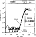
[0052]图5显示了通过使用式(1)所示的单体作为原料而形成的外层阻挡绝缘膜5a和5b的耐Cu扩散性。[0052] FIG. 5 shows Cu diffusion resistance of outer layer
[0053]通过在400nm膜厚度的硅衬底上形成外层阻挡绝缘膜5a和5b、用Cu对所述外层阻挡绝缘膜进行镀敷、然后在350℃下进行热处理七小时之后,利用SIMS(次级离子质谱)来测量深度方向上Cu分布,对所述外层阻挡绝缘膜5a、5b的耐Cu扩散性进行了评价。进行SIMS分析以检查热处理之前和之后在深度方向上Cu分布,所述热处理为通过从硅衬底面进行溅射以防止表面上的Cu与初级离子一起植入。[0053] After forming the outer
[0054]图5A为热处理之前在深度方向上的分布曲线,图5B为热处理之后在深度方向上的分布曲线。根据图5所示的结果发现,在热处理之前和之后,Cu在深度方向上的分布没有变化且通过使用式(1)所示单体形成的外层阻挡绝缘膜5a、5b展示了高耐Cu扩散性。此外,测量的含不饱和烃和无定形碳的有机二氧化硅结构的外层阻挡绝缘膜5a和5b的相对介电常数为3.1。[0054] FIG. 5A is a distribution curve in the depth direction before heat treatment, and FIG. 5B is a distribution curve in the depth direction after heat treatment. According to the results shown in FIG. 5, it was found that the distribution of Cu in the depth direction did not change before and after the heat treatment and the outer layer
[0055]此外还发现,所述外层阻挡绝缘膜5a、5b展示了高膜强度,且相对于内层阻挡绝缘膜4a、4b具有高粘合性能。图6显示了测量结果,其中所述外层阻挡绝缘膜5a、5b展示了高膜强度。在形成500nm膜厚度的外层阻挡绝缘膜5a、5b之后,通过使用纳米压痕仪测量所述外层阻挡绝缘膜的膜强度,来进行所述测量。图6同时显示了典型的SiOCH膜的膜强度和K值,能够看出,根据实施例1的外层阻挡绝缘膜5a、5b的膜强度展示了高达25GPa的值。[0055] It was also found that the outer
[0056]接下来,图7展示了外层阻挡绝缘膜5a和5b的粘合强度的评价结果。通过使用m-ELT进行了所述评价,以评价在SSiCN上形成膜之后的粘合性。图7同时显示了典型的SiOCH膜的粘合强度和K值,能够看出,根据实施例1的外层阻挡绝缘膜5a、5b的粘合强度展示了高达0.22MPa·ml/2的值。[0056] Next, FIG. 7 shows the evaluation results of the adhesive strength of the outer layer
[0057]如上所述,根据实施例1的外层阻挡绝缘膜不仅展示了高耐Cu扩散性,而且展示了高膜强度和高粘合性。[0057] As described above, the outer layer barrier insulating film according to Example 1 exhibited not only high Cu diffusion resistance but also high film strength and high adhesiveness.
[0058]在根据本发明实施例1的半导体装置中,在具有用于覆盖含铜布线3a、3b的表面的内层阻挡绝缘膜4a、4b和在所述内层阻挡绝缘膜4a、4b上堆叠的外层阻挡绝缘膜5a、5b的双层结构中形成了阻挡绝缘膜,且所述双层结构的阻挡绝缘膜4a和4b覆盖所述含铜布线3a、3b。因此,当形成外层阻挡绝缘膜时,所述内层阻挡绝缘膜用作抑制含铜布线表面氧化的缓冲层。因此,伴有在含不饱和烃和无定形碳的有机二氧化硅结构中的外层阻挡绝缘膜展示了耐Cu扩散性以及其相对介电常数小于3.5的事实,其能够降低布线的有效介电常数。因此,能够改善布线信号延迟。In the semiconductor device according to
[0059]此外,就实施例1而言,证实了在含不饱和烃和无定形碳的有机二氧化硅结构中的外层阻挡绝缘膜展示了耐Cu扩散性且其相对介电常数小于3.5。因此,所述内层阻挡绝缘膜可简单用作防止含铜布线表面氧化的缓冲层。因此,能够将所述内层阻挡绝缘膜的膜厚度设定得尽量薄,例如为5nm以下,其处于能够抑制含铜布线表面氧化的范围内。这可尽可能地降低含铜布线所占的体积。[0059] Furthermore, with regard to Example 1, it was confirmed that the outer layer barrier insulating film in the organosilica structure containing unsaturated hydrocarbon and amorphous carbon exhibited resistance to Cu diffusion and its relative dielectric constant was less than 3.5 . Therefore, the inner layer barrier insulating film can be used simply as a buffer layer for preventing oxidation of the copper-containing wiring surface. Therefore, the film thickness of the inner layer barrier insulating film can be set as thin as possible, for example, 5 nm or less, which is within a range capable of suppressing surface oxidation of copper-containing wiring. This minimizes the volume occupied by copper wiring.
实施例2Example 2
[0060]接下来,作为实施例2,描述了一种情况,其中使用SiN、SiCN或SiC作为内层阻挡绝缘膜,并使用具有内层阻挡绝缘膜和外层阻挡绝缘膜的双层结构的阻挡绝缘膜。Next, as
[0061]图8显示了截面图,所述截面图以根据本发明实施例2的半导体装置制造方法的制造步骤的顺序图示。首先,在硅衬底(未示出)上形成300nm的SiO2膜(绝缘膜)11,并在所述SiO2膜11上形成30nm厚的SiCN膜12作为蚀刻终止层。随后,通过等离子CVD法在SiCN膜12上形成80nm厚、相对介电常数为2.55的多孔SiOCH膜13,其将成为第一布线的布线间绝缘膜。其后,也通过等离子CVD法在所述SiOCH膜13上形成120nm厚的SiO2膜14,作为覆盖所述多孔低介电常数膜表面的硬掩模(图8A)。[0061] FIG. 8 shows cross-sectional views illustrating the order of manufacturing steps of the semiconductor device manufacturing method according to
[0062]通过平版印刷和干法蚀刻在所述堆叠绝缘膜中形成布线沟槽1c(图8B)。其后,通过离子溅射在所述衬底的整个表面上形成40nm的TaN膜和Ta膜以及Cu薄膜的阻挡金属膜15,并以所述Cu膜作为电极通过电镀将Cu 16嵌入布线沟槽1内部(图8C)。[0062] A
[0063]然后,在氮气气氛中于350℃下进行热处理三十分钟以用于生长Cu粒子之后,通过CMP除去各层中多余的Cu、Ta、TaN。另外,进行修整直至SiO2膜14的膜厚度变为约30nm,利用剩余的Cu 16在布线沟槽1c内部形成第一布线(含铜布线)16(图8D)。[0063] Then, after performing heat treatment at 350° C. for thirty minutes in a nitrogen atmosphere for growing Cu particles, excess Cu, Ta, and TaN in each layer were removed by CMP. In addition, trimming is performed until the film thickness of SiO 2 film 14 becomes about 30 nm, and first wiring (copper-containing wiring) 16 is formed inside
[0064]接下来,通过等离子CVD法在衬底的整个表面上形成5nm膜厚度的SiN(内层阻挡绝缘膜)17(图8E)。其后,使用异丙基乙烯基二甲氧基硅烷作为原料,通过等离子CVD法在SiN膜17上形成25nm厚的外层阻挡绝缘膜18,所述外层阻挡绝缘膜18在具有耐Cu扩散性的有机二氧化硅结构中(图8F)。此时,在用于形成外层阻挡绝缘膜18的成膜气体中包含氧气。然而,由Cu制成的第一布线16的表面由作为内层阻挡绝缘膜的SiN膜17来覆盖,使得能够抑制第一布线16表面的氧化。[0064] Next, SiN (interlayer barrier insulating film) 17 was formed with a film thickness of 5 nm on the entire surface of the substrate by the plasma CVD method (FIG. 8E). Thereafter, using isopropylvinyldimethoxysilane as a raw material, an outer layer
[0065]此外,作为通孔布线层间绝缘膜,通过等离子CVD法形成100nm、相对介电常数为2.8的多孔SiOCH膜19。然后,作为第二布线层中的布线间绝缘膜,通过等离子CVD法形成110nm、相对介电常数为2.25的多孔SiOCH膜20,并通过等离子CVD法形成120nm的SiO2膜21,作为硬掩模(图8G)。[0065] Furthermore, as a via wiring interlayer insulating film, a
[0066]使用外层阻挡绝缘膜18作为蚀刻终止层,通过平版印刷和各向异性干法蚀刻依次除去一部分SiO2膜21、一部分多孔SiOCH膜20以及一部分多孔SiOCH膜19,以在第一布线层和第二布线层之间形成通孔1e(图8H)。外层阻挡绝缘膜18和通孔布线层间绝缘膜19两者都为有机二氧化硅结构(SiOCH)。然而,C/Si的组成比不同,使得能够确保进行干法蚀刻时的选择比。[0066] Using the outer
[0067]连续地,通过平版印刷和各向异性干法蚀刻除去一部分硬掩模21和一部分布线间绝缘膜20,以形成第二布线层的布线沟槽1c。同时,除去所述通孔底部中的外层阻挡绝缘膜18和内层阻挡绝缘膜17(图8I)。通过使用有机剥离剂除去通孔和沟槽中的蚀刻残余物以及暴露在通孔底部中的Cu表面上的CuO、Cu2O。[0067] Successively, a part of the
[0068]然后,通过与形成第一布线层情况相同的步骤,利用离子溅射法形成40nm的Cu膜和其中依次堆叠TaN膜和Ta膜的阻挡金属膜22,以覆盖第二布线的布线沟槽的内表面和第一布线层与第二布线层之间通孔的内表面,并使用形成的膜作为种子电极,通过电镀来嵌入Cu23(图8J)。[0068] Then, by the same steps as in the case of forming the first wiring layer, a Cu film of 40 nm and a
[0069]然后,如同形成第一布线层中的情况,在氮气气氛中于350℃下进行热处理30分钟以生长Cu粒子。其后,除去各层中多余的Cu、Ta、TaN。另外,进行修整直至SiO2硬掩模的膜厚度变为约30nm,以形成第二布线(含铜布线)23(图8K)。[0069] Then, as in the case of forming the first wiring layer, heat treatment was performed at 350° C. for 30 minutes in a nitrogen atmosphere to grow Cu particles. Thereafter, excess Cu, Ta, and TaN in each layer are removed. In addition, trimming is performed until the film thickness of the SiO 2 hard mask becomes about 30 nm to form a second wiring (copper-containing wiring) 23 (FIG. 8K).
[0070]接下来,如同形成第一布线中的情况,通过等离子CVD法,在整个表面上形成5nm厚的SiN(内层阻挡绝缘膜)24,作为第一阻挡绝缘膜(图8I)。其后,使用异丙基乙烯基二甲氧基硅烷作为原料,通过等离子CVD法,在内层阻挡绝缘膜24上形成具有耐Cu扩散性的有机二氧化硅结构中厚度为25nm的外层阻挡绝缘膜25(图8M)。此外,形成SiO2膜26作为覆盖膜(图8N)。[0070] Next, as in the case of forming the first wiring, a 5 nm thick SiN (interlayer barrier insulating film) 24 was formed on the entire surface by the plasma CVD method as a first barrier insulating film (FIG. 8I). Thereafter, using isopropylvinyldimethoxysilane as a raw material, an outer layer barrier film with a thickness of 25 nm in an organic silicon dioxide structure having Cu diffusion resistance is formed on the inner layer
[0071]在通过平板印刷和蚀刻而在覆盖膜26中将相对于第二布线的接合部分开口之后,通过溅射依次沉积Ti、TiN和Al。通过平版印刷和蚀刻将Al/TiN/Ti堆叠膜加工成垫图案以用于测量电性。[0071] After the bonding portion with respect to the second wiring is opened in the
[0072]图9为上述实施例2所示结构的有效介电常数与通用结构的有效介电常数之间比较的图。与通常使用的SiCN=30nm的阻挡绝缘膜结构相比,能够看出,通过使用堆叠型阻挡绝缘膜结构将有效介电常数降低4.5%,所述结构使用25nm膜厚度的有机二氧化硅结构作为外层阻挡绝缘膜并使用5nm膜厚度的SiN膜作为内层阻挡绝缘膜,如实施例2中所述。[0072] FIG. 9 is a graph showing the comparison between the effective dielectric constant of the structure shown in the above-mentioned
[0073]尽管使用SiN作为内层阻挡绝缘膜,但是当使用SiCN或SiC代替SiN时,也证实有效介电常数以与图9中相同的方式降低。从图9能够看出,在使用SiCN膜作为内层阻挡绝缘膜的堆叠型内层和外层阻挡绝缘膜情况(有机二氧化硅/SiCN)下,所述有效介电常数能够降低约6.2%。[0073] Although SiN was used as the interlayer barrier insulating film, when SiCN or SiC was used instead of SiN, it was also confirmed that the effective dielectric constant decreased in the same manner as in FIG. 9 . As can be seen from FIG. 9, in the case of a stacked inner layer and outer layer barrier insulating film (organic silicon dioxide/SiCN) using a SiCN film as the inner barrier insulating film, the effective dielectric constant can be reduced by about 6.2%. .
实施例3Example 3
接下来,将描述含铜布线具有改性层或金属帽(cap)的情况,作为实施例3。Next, a case where a copper-containing wiring has a modified layer or a metal cap will be described as
[0074]如图10所示,实施例3具有包含大量杂质的改性层6a、6b,其在含铜布线3a、3b表面上形成。作为选择,如图11所示,实施例3具有在含铜布线3a、3b表面上形成的金属帽层7a、7b。[0074] As shown in FIG. 10, Example 3 has modified
[0075]在图10所示的情况下,在绝缘膜1a中形成由阻挡金属2a覆盖的含铜布线3a,在含铜布线3a顶部上堆叠Cu表面改性层6a,并在Cu表面改性层6a上进一步堆叠含不饱和烃和无定形碳的有机二氧化硅组分的阻挡绝缘膜5a。此外,在所述阻挡绝缘膜5a上堆叠绝缘膜1b,在所述绝缘膜1b中形成由阻挡金属2b覆盖的含铜布线3b,在含铜布线3b顶部上堆叠Cu表面改性层6b,并在Cu表面改性层6b上进一步堆叠含不饱和烃和无定形碳的有机二氧化硅组分的阻挡绝缘膜5b。In the case shown in FIG. 10, a copper-containing
[0076]在图10的情况中,将由SiOCH制成的有机二氧化硅结构的化合物用于阻挡绝缘膜5a和5b。此外,尽管在图10中在两步(上部的步骤和下部的步骤)中形成了含铜布线3a和3b,但是含铜布线的堆叠层数目不仅限于如图10所示情况中的“2”。[0076] In the case of FIG. 10, a compound of an organic silicon dioxide structure made of SiOCH is used for the
[0077]在图11所示的情况中,在绝缘膜1a中形成由阻挡金属2a覆盖的含铜布线3a,在含铜布线3a表面上堆叠金属帽层7a,并在金属帽层7a上进一步堆叠含不饱和烃和无定形碳的有机二氧化硅组分的阻挡绝缘膜5a。此外,在阻挡绝缘膜5a上堆叠绝缘膜1b,在绝缘膜1b中形成由阻挡金属2b覆盖的含铜布线3b,在含铜布线3b表面上堆叠金属帽层7b,并在金属帽层7b上进一步堆叠含不饱和烃和无定形碳的有机二氧化硅组分的阻挡绝缘膜5b。In the case shown in FIG. 11, a copper-containing
[0078]在图11的情况中,将由SiOCH制成的有机二氧化硅结构的化合物用于阻挡绝缘膜5a和5b。此外,尽管在图11中在两步(上部的步骤和下部的步骤)中形成了含铜布线3a和3b,但是含铜布线的堆叠层数目不仅限于如图11所示情况中的“2”。[0078] In the case of FIG. 11, a compound of an organic silicon dioxide structure made of SiOCH is used for the
[0079]如上所述,在Cu表面上形成具有耐氧化性的改性层(图10)或金属帽层(图11),作为用于抑制含铜布线表面氧化的氧化防止层,所述氧化是由在形成具有耐Cu扩散性的有机二氧化硅膜时在成膜气体中包含的O引起的,并在其上形成具有耐Cu扩散性的有机二氧化硅结构的阻挡绝缘膜5a和5b。[0079] As described above, a modified layer (FIG. 10) or a metal cap layer (FIG. 11) having oxidation resistance is formed on the surface of Cu as an oxidation prevention layer for suppressing oxidation of the surface of copper-containing wiring, which oxidizes It is caused by O contained in the film-forming gas when the organic silicon dioxide film having Cu diffusion resistance is formed, and the
[0080]接下来,通过参考图12,将对图10所示的半导体装置,即在含铜布线上形成具有耐氧化性的改性层的情况进行说明。[0080] Next, by referring to FIG. 12, the semiconductor device shown in FIG. 10, that is, the case where a modification layer having oxidation resistance is formed on a copper-containing wiring will be described.
[0081]在图12A中,在绝缘膜1a中形成由阻挡金属2a覆盖的含铜布线3a,在所述含铜布线3a表面上形成Cu表面改性层6a,并在所述Cu表面改性层6a上形成阻挡绝缘膜5a。通过与图12b中和其后所述的相同方法形成图12A中所述的结构。In FIG. 12A, a copper-containing
[0082]首先,在阻挡绝缘膜5a上形成绝缘膜1b(图12B),其后进行平版印刷和各向异性蚀刻以在绝缘膜中形成布线沟槽1c和布线孔1d(图12C)。然后,在布线沟槽1c和布线孔1d的内壁上形成阻挡金属膜2b,并在将嵌入到所述布线沟槽1c和布线孔1d内部的阻挡金属绝缘膜2b上沉积Cu 3b(图12D)。随后,进行热处理以生长Cu粒子。将所述热处理的温度设定为200℃~400℃,并将其时间设定为30秒~1小时。[0082] First, an insulating
[0083]然后,通过使用诸如CMP的研磨技术,除去多余的Cu和阻挡金属(图12E)。接下来,通过将衬底温度设定在200℃~350℃内,在真空室内将SiH4气照射到表面上,以在含铜布线1b表面上形成CuSi。随后,在同一个室内照射NH3等离子体,以在含铜布线3b表面上形成由CuSiN制成的表面改性层6b(图12F)。其后,通过实施例1中所述的等离子CVD法,形成具有耐Cu扩散性和相对介电常数小于3.5的有机二氧化硅结构的阻挡绝缘膜6b(图12G)。通过重复图12B~12G,能够形成更上侧的布线层。此外,在上述说明中,使用同时形成布线沟槽和布线孔的双重金属镶嵌法。然而,当通过使用单重金属镶嵌法形成布线层时,也使用相同的方法。[0083] Then, by using a grinding technique such as CMP, excess Cu and barrier metal are removed (FIG. 12E). Next, by setting the substrate temperature within 200°C to 350°C, SiH 4 gas was irradiated onto the surface in a vacuum chamber to form CuSi on the surface of the copper-containing
[0084]接下来,通过参考图13,将对图11所示的半导体装置即在含铜布线上形成金属帽层的情况进行说明。[0084] Next, by referring to FIG. 13, the semiconductor device shown in FIG. 11, that is, the case where a metal cap layer is formed on a copper-containing wiring will be described.
[0085]在图13A中,在绝缘膜1a中形成由阻挡金属2a覆盖的含铜布线3a,在含铜布线3a顶部上形成金属帽层6a,并在金属帽层6a上形成阻挡绝缘膜5a。通过与图13B中和其后所述方法相同的方法来形成图13A中所述的结构。In FIG. 13A, a copper-containing
[0086]首先,在阻挡绝缘膜5a上形成绝缘膜1b(图13B),其后进行平版印刷和各向异性蚀刻以在绝缘膜中形成布线沟槽1c和布线孔1d(图13C)。然后,在布线沟槽1c和布线孔1d的内壁上形成阻挡金属膜2b,并在将嵌入到所述布线沟槽1c和布线孔1d内部的阻挡金属绝缘膜2b上沉积Cu 3b(图13D)。随后,进行热处理以生长Cu粒子。将所述热处理的温度设定为200℃~400℃,并将其时间设定为30秒~1小时。接下来,通过使用诸如CMP的研磨技术除去多余的Cu和阻挡金属,以形成含铜布线3b(图13E)。然后,通过使用无电镀法在所述含铜布线3b表面上选择性地形成例如CoWP的金属帽层7b(图13F)。[0086] First, an insulating
[0087]其后,通过实施例1中所述的等离子CVD法,形成具有耐Cu扩散性和相对介电常数小于3.5的有机二氧化硅结构的阻挡绝缘膜7b(图13G)。通过重复图13B~13G,能够形成更上侧布线层。金属帽层通过无电镀法形成,并且除了利用CoWP之外,它可利用CoWB、CoSnP、CoSnB、NiB或NiMoB来形成。此外,在上述说明中,使用同时形成布线沟槽和布线孔的双重金属镶嵌法。然而,当通过使用单重金属镶嵌法形成布线层时,也使用相同的方法。[0087] Thereafter, by the plasma CVD method described in Example 1, a
[0088]在本发明的实施例3中,含铜布线3a、3b的表面由表面改性层或金属帽层6a、6b覆盖。因此,在形成阻挡绝缘膜7a、7b时,可阻止含铜布线3a、3b表面被氧化。[0088] In
[0089]此外,就实施例3而言,当存在在含铜布线3a、3b表面上形成的具有耐氧化性的表面改性层或金属帽层7a、7b时,不必使用SiN、SiCn等的内层阻挡绝缘膜4a、4b。就实施例3而言,使用有机二氧化硅结构的30nm膜厚度、相对介电常数为3.1的阻挡绝缘膜7a、7b,与通常使用的SiCN膜为30nm厚的阻挡绝缘膜结构的情况相比,能够将有效相对介电常数降低7.6%。[0089] Furthermore, in the case of Example 3, when there are surface modification layers having oxidation resistance or
[0090]接下来,将描述在由含铜布线3a、3b表面上形成的表面改性层或金属帽层上形成阻挡绝缘膜的情况,作为实施例4。[0090] Next, a case where a barrier insulating film is formed on the surface modification layer or the metal cap layer formed on the surface of the copper-containing
实施例4Example 4
[0091]在实施例4中,提供具有耐氧化性的改性层6a、6b(图14)或金属帽层6a、6b(图15),作为氧化防止层以抑制含铜布线表面的氧化,所述氧化由在形成具有耐Cu扩散性的有机二氧化硅膜(阻挡绝缘膜)时成膜气体中所包含的O引起,在其上提供由SiN、SiCN或SiC制成的膜厚度小于5nm的内层阻挡绝缘膜4a、4b,并在其上进一步形成具有耐Cu扩散性的有机二氧化硅膜,作为阻挡绝缘膜5a和5b。In
[0092]接下来,通过参考图16,将描述图14所示的半导体装置,尤其是布线结构。图16显示了在含铜布线3a、3b表面上形成具有耐氧化性的改性层6a、6b的情况。[0092] Next, by referring to FIG. 16, the semiconductor device shown in FIG. 14, particularly the wiring structure will be described. FIG. 16 shows a state where modified
[0093]在图16A中,在绝缘膜1a中形成由阻挡金属2a覆盖的含铜布线3a,在含铜布线3a顶部上堆叠Cu表面改性层6a,并在所述Cu表面改性层6a上形成内层阻挡绝缘膜5a。通过与图16B中和其后所述相同的方法形成图16A所示的结构。In FIG. 16A, a copper-containing
[0094]首先,在阻挡绝缘膜1a上形成绝缘膜1b(图16B),其后进行平版印刷和各向异性蚀刻以在绝缘膜中形成布线沟槽1c和布线孔1d(图16C)。然后,在布线沟槽1c和布线孔1d的内壁上形成阻挡金属膜2b,并在将嵌入到所述布线沟槽1c和布线孔1d内部的阻挡金属绝缘膜2b上沉积Cu 3b(图16D)。随后,进行热处理以生长Cu粒子。将所述热处理的温度设定为200℃~400℃,并将其时间设定为30秒~1小时。然后,通过使用诸如CMP的研磨技术除去多余的Cu和阻挡金属以形成含铜布线3b(图16E)。[0094] First, an insulating
[0095]接下来,通过将衬底温度设定在200℃~350℃内,在真空室内将SiH4气照射到表面上,以在含铜布线3b表面上形成CuSi。此外,在相同室内,照射等离子体,以形成由CuSiN制成的表面改性层6b(图16F)。随后,在相同室内,通过等离子CVD法形成由SiN、SiCN或SiC制成的内层阻挡绝缘膜4b(图16G)。其后,通过实施例1中所述的等离子CVD法,在内层阻挡绝缘膜4b上形成具有耐Cu扩散性和相对介电常数小于3.5的有机二氧化硅结构的外层阻挡绝缘膜5b(图16H)。通过重复图16B~16H,能够形成更上侧布线层。此外,在上述说明中,使用同时形成布线沟槽和布线孔的双重金属镶嵌法。然而,当通过使用单重金属镶嵌法形成布线层时,也使用相同的方法。[0095] Next, by setting the substrate temperature within 200°C to 350°C, SiH 4 gas was irradiated onto the surface in a vacuum chamber to form CuSi on the surface of the copper-containing
[0096]使用例如SiH4气和N2气或NH3气的复合气体簇离子束,使得可共同进行用于在含铜布线3b表面上形成改性层6b的加工(图16F)和用于形成内层阻挡绝缘膜4b的加工(图16G)。更具体地,将复合气体簇离子束照射在晶片表面上,以形成改性层6a、6b和含铜布线3a、3b表面上的内层阻挡膜4a、4b。当照射到含铜布线3a、3b上的气体簇离子束的照射时间短时,在几nm深度的极浅部分中形成CuSiN的改性层6a、6b。这是因为簇尺寸大,使得即使加速度能量高,每个原子的能量也通常为5eV以下。因此,离子束难以植入到深度方向中。当以这种状态连续进行照射时,在含铜布线3a、3b表面上不仅形成改性层6a、6b,而且形成SiN的内层阻挡绝缘膜4a、4b。通过改变加速度电压和衬底温度,能够控制改性层6a和6b的厚度。[0096] Using, for example, SiH 4 gas and N 2 gas or NH 3 gas complex gas cluster ion beam, so that the processing for forming the modified
[0097]接下来,通过参考图17,将描述图15所示的半导体装置,尤其是布线结构。图17显示了在含铜布线3a、3b表面上形成具有耐氧化性的金属帽层6a、6b的情况。[0097] Next, by referring to FIG. 17, the semiconductor device shown in FIG. 15, particularly the wiring structure will be described. FIG. 17 shows the case where
[0098]在图17A中,在绝缘膜1a中形成由阻挡金属2a覆盖的含铜布线3a,在含铜布线3a表面上形成金属帽层6a,并在所述金属帽层6a上形成内层阻挡绝缘膜5a。通过与图17B中和其后所述相同的方法,形成图17A中所述的结构。In FIG. 17A, a copper-containing
[0099]首先,在阻挡绝缘膜1a上形成绝缘膜1b(图17B),其后进行平版印刷和各向异性蚀刻以在绝缘膜中形成布线沟槽1c和布线孔1d(图17C)。然后,在布线沟槽1c和布线孔1d的内壁上形成阻挡金属膜2b,并在将嵌入到所述布线沟槽1c和布线孔1d内部的阻挡金属绝缘膜2b上沉积Cu 3b(图17D)。随后,进行热处理以生长Cu粒子。将所述热处理的温度设定为200℃~400℃,并将其时间设定为30秒~1小时。然后,通过使用诸如CMP的研磨技术除去多余的Cu和阻挡金属,以形成含铜布线3b(图17E)。[0099] First, an insulating
[0100]然后,通过使用无电镀法,在所述含铜布线3b表面上选择性地形成例如CoWP的金属帽层7b(图17F)。随后,通过等离子CVD法,在金属帽层7b上形成由SiN、SiCN或SiN制成的内层阻挡绝缘膜4b(图17G)。其后,通过实施例1中所述的等离子CVD法,在金属帽层7b上形成具有耐Cu扩散性和相对介电常数小于3.5的有机二氧化硅结构的阻挡绝缘膜5b(图17H)。通过重复图17B~17H,能够形成更上侧布线层。通过无电镀法,利用CoWP形成金属帽层7a、7b。然而,所述金属帽层7a、7b也可利用CoWB、CoSnP、CoSnB、NiB或NiMoB形成。此外,在上述说明中,使用同时形成布线沟槽和布线孔的双重金属镶嵌法。然而,当通过使用单重金属镶嵌法形成布线层时,也使用相同的方法。[0100] Then, by using an electroless plating method, a
实施例5Example 5
[0101]图18显示了根据本发明实施例5的含铜布线的截面图。如图18所示,在实施例5中,在绝缘膜41中形成由阻挡金属42a覆盖的含铜布线43a,在含铜布线43a表面上形成改性层44a,在改性层44a上形成阻挡绝缘膜45a,并在阻挡绝缘膜45a上形成通孔绝缘膜46和沟道绝缘膜47。此外,在沟道绝缘膜47中形成由阻挡金属42b覆盖的含铜布线43b,并通过通孔绝缘膜46的通孔将一部分含铜布线43b电连接到下层含铜布线43a上。此外,在上层含铜布线43b表面上形成改性层44b,并在改性层44a上形成阻挡绝缘膜45b。[0101] FIG. 18 shows a cross-sectional view of a copper-containing wiring according to
[0102]在实施例5中,改性层44a、44b用作氧化防止层以抑制含铜布线43a、43b表面的氧化,所述氧化是由在形成具有耐Cu扩散性的有机二氧化硅结构的阻挡绝缘膜45a、45b时在成膜气体中包含的O引起的。然后,在所述具有耐氧化性的改性层44a、44b上形成具有耐Cu扩散性的有机二氧化硅结构的阻挡绝缘膜45a、45b。[0102] In
[0103]接下来,通过参考图19,将对用于制造图18所示实施例5布线结构的方法进行描述。图19显示了含铜布线30的放大状态,其对应含铜布线43a和43b。在进行CMP之后,在含铜布线30表面上形成极薄的氧化物膜CuOX31(图19A)。[0103] Next, by referring to FIG. 19, a method for manufacturing the wiring structure of
[0104]在所述CuOX31上施加防蚀剂32,以防止进一步氧化(图19B)。然后,在形成具有耐氧化性的改性层之前,在氮气气氛中进行热处理,以除去防蚀剂32(图19C)。此时,极薄的氧化物膜CuOX31未被除去而是残留在含铜布线30的表面上(图19C)。其后,在同一个室内通过等离子CVD法形成由SiN、SiCN或SiC制成的阻挡绝缘膜33(图19D)。[0104] A
[0105]通过在形成阻挡绝缘膜33时将含铜布线30的表面暴露于SiH4气中,Si开始从含铜布线30表面向内部扩散。然而,CuOX31的存在阻碍了Si扩散,且Si累积在含铜布线30表面附近。因此,形成精细的氧扩散阻挡膜33,而不会明显增加布线电阻,因此能够提高耐氧化性(图19D)。更优选地,可利用NH3等离子体对氧扩散阻挡膜33进行脱氧,并可在含铜布线30表面上形成由Cu-Si-N制成的具有高耐氧化性的改性层34(图19C)。[0105] By exposing the surface of the copper-containing
[0106]此外,通过在N2气氛中进行热处理之后,利用NH3等离子体进行表面处理以对CuOX31脱氧的同时,在最外表面上形成氮化物可提高耐氧化性。而且,通过在N2气氛中进行热处理之后将表面暴露于SiH4气中,然后利用NH3等离子体来封端Cu活性位,可提高耐氧化性。作为选择,通过在N2气氛中进行热处理之后将表面暴露于SiH4和NH3的混合气中以脱氧/除去最外表面上的CuOX层并通过同时向Cu表面添加Si,可形成改性层。[0106] Furthermore, oxidation resistance can be improved by forming nitrides on the outermost surface while performing surface treatment with NH 3 plasma to deoxidize
[0107]而且,通过照射复合气体簇离子的步骤,可形成具有高耐氧化性的改性层,所述复合气体簇离子包含SiH4以及选自NH3、N2、CH3、C2H2和C2H4中的至少一种。[0107 ] And, by irradiating the step of composite gas cluster ions, a modified layer with high oxidation resistance can be formed . At least one of 2 and C 2 H 4 .
[0108]通过使用等离子CVD法,在具有高耐氧化性的改性层上形成阻挡绝缘膜,所述绝缘膜以上述方式形成。下文中,通过参考图20A,将对形成上层布线的步骤进行描述。在图20A中,在绝缘膜41中形成了由阻挡金属42a覆盖的含铜布线43a,并在所述含铜布线43a表面上形成了改性层44a和阻挡绝缘膜45a。[0108] By using the plasma CVD method, a barrier insulating film was formed on the modified layer having high oxidation resistance, the insulating film being formed in the above-described manner. Hereinafter, by referring to FIG. 20A , the steps of forming upper layer wiring will be described. In FIG. 20A, a copper-containing
[0109]在所述阻挡绝缘膜45上依次形成了通孔绝缘膜46、沟道绝缘膜47和硬掩模48(图21B)。可使用单独装置分别形成那些膜,或者使用同一个室,连续形成所述阻挡绝缘膜45a、通孔绝缘膜46、沟道绝缘膜47和硬掩模48。[0109] A via insulating
[0110]图34为显示用于形成本发明实施例5的阻挡绝缘膜45a、通孔绝缘膜46、沟道绝缘膜47和硬掩模48的等离子CVD装置的实例的示意图。图34所示的等离子CVD装置250具有反应室210、气体供应部件220、真空泵230以及高频电源240。所述气体供应部件220通过气体供应管道222连接到反应室210,并且真空泵230通过气体排出管道236连接到反应室210,所述气体排出管道236在其中部布置有阀门232和冷却汽水阀(cooling trap)234。此外,高频电源240通过高频电缆244连接到反应室210,所述高频电缆244在其中部布置有匹配箱242。34 is a schematic diagram showing an example of a plasma CVD apparatus for forming the
[0111]在所述反应室210内部,将衬底加热部件203(保持/加热成膜元件201)和喷淋头(用作连接到气体供应管道222一端的气体喷出部件)彼此相对设置。将地线207连接到衬底加热部件203,并将高频电缆244连接到喷淋头205。因此,通过借助于气体供应管道222将原料气等从气体供应部件220供应至喷淋头205,并通过将由高频电源240产生的高频电在通过位于高频电缆244中部的匹配箱242转换成预定频率之后供应至喷淋头205,能够将衬底加热部件203和喷淋头205之间的空间内的气体制成等离子体。[0111] Inside the
[0112]将在其中部布置有流量控制器224和阀门226的清洁气体供应管道228连接到气体供应管道222。通过在阀门232和冷却汽水阀234之间区域内从气体排出管道236分岔来提供排泄管238。优选通过在气体供应部件222周围提供加热器(未示出)来加热气体供应管道222,以防止各种气体在输送过程中变成液体。类似地,也优选通过在反应室210周围提供加热器(未示出)来加热反应室210。[0112] A cleaning
[0113]图35显示了气体供应部件220的内部。汽化控制单元VU1和VU2具有:储存液体有机硅氧烷材料301、303的原料罐302;借助于加压气体供应管道304向原料罐302内部供应加压气体的加压气体供应装置306;其一端插入原料罐302内部的原料输送管道308;在原料输送管道308中部提供的液体流量控制部件310;以及布置在原料输送管道308另一末端侧的汽化部件312。上述液体流量控制部件310具有两个阀310a、310b,以及布置在阀310a和310b之间的液体流量控制器310c。上述汽化部件具有在前述原料输送管道308另一末端侧上提供的阀312a,和连接到前述原料输送管道308另一末端的汽化器312b。[0113] FIG. 35 shows the inside of the
[0114]此外,各个汽化控制单元VU1和VU2具有:用于载气或稀释气的气体供应罐314(下文中称为“载气供应罐”);和液体流量控制部件310和汽化部件312之间提供以将载气供应罐314中的载气或稀释气供应至原料化合物输送管道308的管道316。在管道316中部提供气体流量控制部件318,所述气体流量控制部件318具有两个阀318a、318b以及布置在两个阀318a、318b之间的气体流量控制器318c。在汽化控制单元VU1中,当借助于加压气体供应管道304将加压气体从加压气体供应装置306供应至原料罐302内部时,原料罐302的内部压力升高。因此,借助于原料输送管道308将原料罐302内液体形式的第一有机硅氧烷原料301向汽化部件312输送,并在途中与载气或稀释气混合,以到达汽化部件312。已经到达汽化部件312的液体有机硅氧烷原料301因为汽化部件312的导入部件处压力的降低和由加热器(未示出)施加的热而汽化。[0114] Furthermore, each of the vaporization control units VU1 and VU2 has: a
[0115]类似地,在汽化控制单元VU2中,当借助于加压气体供应管道304将加压气体从加压气体供应装置306供应至原料罐302内部时,原料罐302的内部压力升高。因此,借助于原料输送管道308将原料罐302内液体形式的第二有机硅氧烷原料302向汽化部件312输送,并在途中与载气或稀释气混合,以到达汽化部件312。已经到达汽化部件312的液体环状有机硅氧烷原料301因为汽化部件312的导入部件处压力的降低和由加热器(未示出)施加的热而汽化。[0115] Similarly, in the vaporization control unit VU2, when pressurized gas is supplied from the pressurized
[0116]此外,还可向汽化控制单元VU1的原料罐302内部引入两种以上的有机二氧化硅材料,并在汽化控制单元VU1的汽化部件312中同时汽化该材料,而不使用汽化控制单元VU2。[0116] In addition, it is also possible to introduce more than two kinds of organic silicon dioxide materials into the
[0117]为了平稳地在各个汽化器312b中进行汽化,优选在液体流量控制部件310的阀门310c的下游侧上的原料化合物输送管道308的周围提供加热器,并加热原料化合物输送管道308。类似地,为了防止各种气体变成液体,优选在各个气体排出管道320、352和混合器340的周围提供加热器,以加热那些气体中的每一种。[0117] In order to smoothly perform vaporization in each
[0118]作为通过使用等离子CVD装置250而形成有机硅膜的方法,将成膜元件201如半导体衬底放置在衬底加热部件203上,并在打开阀232的同时启动真空泵230以将反应室210内部的初始真空度变为几个托。从反应室210排出的气体中的水分通过冷却汽水阀234除去。然后,将原料气(气态环状有机硅氧烷气体)与载气或稀释气一起从气体供应部件220供应至反应室210。同时,启动高频电源240和匹配箱242以向反应室210供应预定频率的高频电。[0118] As a method of forming an organic silicon film by using the
[0119]此时,通过对应的流量控制部件318对各种气体的流量进行控制,以在混合器340中生成预定组成的混合气,并将其供应至反应室210。优选将反应室210中原料气的分压适当地选定在约13~400Pa的范围内。此外,优选通过控制真空泵230的操作,将成膜时反应室210中的气压设定在约133~1333Pa的范围内。通过使用衬底加热部件3来加热成膜元件1,能够将成膜时成膜元件201的表面温度适当设定在100~400℃的范围内。更具体地,表面温度优选在250~350℃的范围内。如上所述,根据所使用化合物原料的种类,在供应原料气之前,将所述化合物原料供应至反应室210。[0119] At this time, the flow rates of various gases are controlled by the corresponding flow control parts 318 to generate a mixed gas of a predetermined composition in the
[0120]当在这种条件下成膜时,作为原料气的环状有机硅氧烷原料的分子被等离子体激发,且呈活化状态的分子到达成膜元件201的表面,以在那里形成绝缘膜。当绝缘膜包括具有不饱和键的基团时,所述被等离子体激发而活化的有机硅化合物分子到达成膜元件1的表面并接收进一步来自衬底加热部件3的热能。因此,基团中的不饱和键打开,分子间的热聚合推进,由此生长绝缘膜。[0120] When the film is formed under such conditions, the molecules of the cyclic organosiloxane raw material as the raw material gas are excited by the plasma, and the molecules in an activated state reach the surface of the film-forming
[0121]为了清洁反应室210,可使用气体如三氟化氮(NF3)、六氟化硫(SF6)、四氟甲烷(CF4)、六氟乙烷(C2F6)等。可以根据需要将那些气体与氧气、臭氧气体等混合而用作混合气。借助于清洁气体供应管道228将清洁气体供应至反应室210。如同成膜中的情况,在喷淋头205和衬底加热部件3之间施加高频电以诱导用于进行反应室210清洁的等离子体。使用通过使用远程等离子体等而预先使其处于等离子体状态的清洁气体也是有效的。[0121] In order to clean the
[0122]在该实施例中,通过使用储存在汽化控制单元VU1的原料罐302内的具有式2所示的环状有机硅氧烷结构的原料,和储存在汽化控制单元VU2的原料罐302内的具有式4所示的直链有机硅氧烷结构的原料,来形成膜。In this embodiment, by using the raw material having the cyclic organosiloxane structure shown in
[化学式2][chemical formula 2]

[化学式4][chemical formula 4]

[0123]其后,进行平版印刷和各向异性蚀刻以在绝缘膜46和47中形成布线沟槽1c和布线孔1d(图20C)。然后,在布线沟槽1c和布线孔1d的内壁上形成阻挡金属42b,并在将嵌入到布线沟槽1c和布线孔1d内部的阻挡金属绝缘膜42b上沉积Cu 43b(图20D)。随后,进行热处理以生长Cu颗粒。将热处理温度设定为200℃~400℃,并将其时间设定为30秒~1小时。然后,通过使用研磨技术如CMP来除去多余的Cu和阻挡金属以形成含铜布线43b,然后在所述含铜布线43b表面上形成具有高耐氧化性的改性层44b,并在其上形成阻挡绝缘膜45a(图20E)。[0123] Thereafter, lithography and anisotropic etching are performed to form
[0124]接下来,将详细描述根据本发明实施例5的半导体装置。图21显示了通过在含铜布线和CuOX上施加防蚀剂32之后而在N2气氛中进行热处理并通过对残留在表面上的防蚀剂32的残留状态进行热沉积分析而得到的质量数78的光谱。图22A显示了在N2气氛中进行热处理之前的状态,图22B显示了从在N2气氛中进行热处理10秒之后的结果。图22A中在250℃点附近处观察到的峰是由于防蚀剂32产生的,能够看出,当在N2气氛中的热处理在250℃以上进行时,能够除去防蚀剂。图22显示了在250℃点附近处的峰面积相对于热处理时间的曲线,这表明了在真空下进行热处理的情况相对于在N2气氛中的情况。在N2气氛中,可通过进行热处理10秒以上来除去防蚀剂,而在真空下即使进行热处理60秒也不可能除去防蚀剂。因此,证实了N2气氛热处理的优势。[0124] Next, a semiconductor device according to
[0125]图23显示了在N2气氛中进行热处理、照射SiH4、进行NH3等离子处理以在含铜布线表面上形成具有耐氧化性的改性层、然后将高温状态的衬底暴露于空气中以进行强制氧化之后,薄层电阻随SiH4流量而变化的曲线。23 shows heat treatment in N 2 atmosphere, irradiation of SiH 4 , NH 3 plasma treatment to form a modified layer with oxidation resistance on the copper-containing wiring surface, and then exposing the substrate in a high temperature state to Curves of sheet resistance as a function of SiH flow rate after forced oxidation in air.
[0126]当通过在N2气氛中的热处理来除去防蚀剂时,极薄的CuOX膜残留在含铜布线的最外表面上。这可抑制Si因照射SiH4而扩散到含铜布线内部。认为因此能够抑制膜层电阻因照射SiH4而显著增大。同时,通过NH3等离子处理,将在含铜布线表面上累积的Si原子制成氮化物,并形成高耐氧化性的改性层。从而,能够抑制氧扩散入含铜布线内部。图24显示了在距同一试样表面5nm深度处通过X射线光电子光谱分析而得到的氧浓度结果。根据该结果能够看出,SiH4照射抑制氧的扩散。从SiH4流量为25sccm的点处能够证实这种效果,能够看出,在100sccm以上的点处,完全抑制了氧化。如上所述,这种表面处理可形成具有高耐Cu氧化性的改性层,而含铜布线的薄层电阻仅小幅增加。[0126] When the corrosion resist was removed by heat treatment in the N 2 atmosphere, an extremely thin CuO x film remained on the outermost surface of the copper-containing wiring. This suppresses the diffusion of Si into the interior of the copper-containing wiring due to irradiation of SiH 4 . It is considered that it is thus possible to suppress a significant increase in film layer resistance due to irradiation of SiH 4 . At the same time, Si atoms accumulated on the surface of copper-containing wiring are made into nitrides by NH3 plasma treatment, and a modified layer with high oxidation resistance is formed. Accordingly, diffusion of oxygen into the interior of the copper-containing wiring can be suppressed. Fig. 24 shows the results of oxygen concentration analyzed by X-ray photoelectron spectroscopy at a depth of 5 nm from the surface of the same sample. From this result, it can be seen that SiH 4 irradiation inhibits the diffusion of oxygen. This effect can be confirmed from the point where the SiH 4 flow rate is 25 sccm, and it can be seen that oxidation is completely suppressed at the point above 100 sccm. As mentioned above, this surface treatment can form a modified layer with high resistance to Cu oxidation with only a small increase in sheet resistance of copper-containing wiring.
[0127]如上所述,通过照射SiH4形成了具有耐氧化性的改性层。通过使用SiH4和NH3的混合气,也可以在表面上形成含Cu、Si、N的具有耐氧化性的改性层。[0127] As described above, a modified layer having oxidation resistance was formed by irradiating SiH 4 . By using a mixed gas of SiH 4 and NH 3 , an oxidation-resistant modified layer containing Cu, Si, and N can also be formed on the surface.
[0128]通过使用实施例5所示的方法,在以上述方式形成的具有高耐氧化性的改性层上形成了阻挡绝缘膜。图25显示了通孔绝缘膜中Cu的扩散,其通过使用次级离子质谱分析(SIMS分析)法而测得,所进行的SIMS法是关于以上述方式形成的阻挡绝缘膜的Cu扩散阻挡特性。经证实,如同正常使用的SiCN阻挡的情况,抑制了Cu扩散。此外,图26为显示了以上述方式形成的阻挡绝缘膜的电流-电压特性曲线。经证实,与正常SiCN阻挡的情况相比,泄漏电流更低且耐压更高。[0128] By using the method shown in Example 5, a barrier insulating film was formed on the modified layer having high oxidation resistance formed in the above-described manner. FIG. 25 shows the diffusion of Cu in the via-hole insulating film, which was measured by using the secondary ion mass spectrometry (SIMS analysis) method performed on the Cu diffusion barrier properties of the barrier insulating film formed in the above-mentioned manner. . Cu diffusion was confirmed to be suppressed, as is the case with normally used SiCN barriers. In addition, FIG. 26 is a graph showing the current-voltage characteristics of the blocking insulating film formed in the above-described manner. It was confirmed that the leakage current was lower and the withstand voltage was higher than that of the normal SiCN barrier.
[0129]此外,在同一个室内连续形成了第二阻挡绝缘膜45a、通孔绝缘膜46、沟道绝缘膜47和硬掩模48。可通过变换等离子聚合的成膜条件,使用一种单体,在同一个室内形成所述第二阻挡绝缘膜45a、通孔绝缘膜46、沟道绝缘膜47和硬掩模48。作为选择,可通过变换两种以上单体的比例来形成所述第二绝缘膜45a、通孔绝缘膜46、沟道绝缘膜47和硬掩模48。[0129] Furthermore, the second
[0130]使用具有式5所示的直链有机二氧化硅结构的原料来形成阻挡绝缘膜45a。[0130] A raw material having a linear organic silica structure shown in
[化学式5][chemical formula 5]

[0131]将图35所示VU1侧的原料罐302内的原料单体通过从加压气体供应装置306供应的He气压出,并将其与由载气供应罐306供应的He气一起导入汽化部件312。引入到汽化部件312的原料单体优选为0.1g/分钟~10g/分钟,包括两个端值,更优选为2g/分钟以下。将原料单体在汽化部件中汽化,并将其与由载气供应罐306供应的He气一起导入反应室210。载气供应量优选为50sccm~5000sccm,包括两个端值,更优选为2000sccm以下。在反应室210中,通过由高频电源240供应的13.56MHz的高频,利用等离子聚合反应形成膜。由所述高频电源240所供应的功率优选为2000W以下,更优选为1000W以下。此外,成膜时反应室210内的压力优选为133~1333Pa。The raw material monomer in the
[0132]通过使用具有式3所示的环状有机二氧化硅结构的原料和具有式5所示的直链有机二氧化硅结构的原料,形成通孔绝缘膜46。[0132] By using a raw material having a cyclic organosilica structure represented by
[化学式3][chemical formula 3]

[0133]通过由加压气体供应装置306供应的He气,将图35所示VU1侧原料罐302内由式5所示的原料单体压出,并将其与由载气供应罐306供应的He气一起导入汽化部件312。导入到汽化部件312的原料单体优选为0.1g/分钟~10g/分钟,包括两个端值,更优选为2g/分钟以下。将原料单体在汽化部件312中汽化,并将其与由载气供应罐306供应的He气一起导入混合器340。载气供应量优选为50sccm~5000sccm,包括两个端值,更优选为2000sccm以下。同时,通过由加压气体供应装置306供应的He气,将VU2侧原料罐302内由式3所示的原料单体压出,并将其与载气供应罐306供应的He气一起导入汽化部件312中。引入到汽化部件312中的原料单体优选为0.1g/分钟~10g/分钟,包括两个端值,更优选为2g/分钟以下。将原料单体在汽化部件312中汽化,并将其与由载气供应罐306供应的He气一起导入混合器340。导入到混合器340中的式5所示原料单体与式3所示原料单体的混合比为1∶9~9∶1。将流经混合器340之后汽化的原料单体和载气导入反应室210。在反应室210内,通过由高频电源240供应的13.56MHz的高频,利用等离子聚合反应形成膜。由高频电源240供应的功率优选为2000W以下,更优选为1000W以下。此外,成膜时反应室210内的压力优选为133~1333Pa。By the He gas supplied by the pressurized
[0134]使用具有式3所示的直链有机二氧化硅结构的原料来形成沟道绝缘膜47。通过由加压气体供应装置306供应的He气,将图35所示VU2侧原料罐302内的原料单体压出,并将其与由载气供应罐306供应的He气一起导入汽化部件312中。导入汽化部件312中的原料单体优选为0.1g/分钟~10g/分钟,包括两个端值,更优选为2g/分钟以下。将原料单体在汽化部件312中汽化,并将其与由载气供应罐306供应的He气一起导入反应室210中。载气供应量优选为50sccm~5000scc,包括两个端值,更优选为2000sccm以下。在反应室210内,通过由高频电源240供应的13.56MHz的高频,利用等离子聚合反应形成膜。由所述高频电源240供应的功率优选为2000W以下,更优选为1000W以下。此外,在成膜时反应室210内的压力优选为133~1333Pa。[0134] The
[0135]使用具有式5所示直链有机二氧化硅结构的原料来形成硬掩模48。通过由加压气体供应装置306供应的He气,将图35所示VU1侧原料罐302内的原料单体压出,并将其与由载气供应罐306供应的He气一起导入汽化部件312。导入汽化部件312的原料单体优选为0.1g/分钟~10g/分钟,包括两个端值,更优选为2g/分钟以下。将原料单体在汽化部件312中汽化,并将其与由载气供应罐306供应的He气一起导入反应室210。载气供应量优选为50sccm~5000sccm,包括两个端值,更优选为2000sccm以下。在反应室210中,通过由高频电源240供应的13.56MHz的高频,利用等离子聚合反应形成膜。由所述高频电源240供应的功率优选为2000W以下,更优选为1000W以下。此外,在成膜时反应室210内的压力优选为133~1333Pa。[0135] The
[0136]在同一个室内,通过连续进行用于阻挡绝缘膜45a、通孔绝缘膜46、沟道绝缘膜47和硬掩模48的两个以上连续步骤来形成膜。作为选择,可通过使用不同成膜装置来形成那些膜。[0136] In the same chamber, films are formed by successively performing two or more consecutive steps for the
[0137]图27显示了通过使用X射线光电子光谱对元素分布进行的深度方向上的分析结果。通过以这种方式在同一个室内连续形成阻挡绝缘膜45a、通孔绝缘膜46、沟道绝缘膜47和硬掩模48,能够减少待提供装置的数量并预计提高产量。因此,可削减成本。[0137] FIG. 27 shows the results of analysis in the depth direction of element distribution by using X-ray photoelectron spectroscopy. By successively forming the
[0138]通过图16所示步骤制造了具有上层和下层的双层Cu布线(含铜布线)构型的半导体装置,所述装置呈以上述方式形成的堆叠绝缘膜结构。[0138] A semiconductor device having a double-layer Cu wiring (copper-containing wiring) configuration of upper and lower layers in a stacked insulating film structure formed in the above-described manner was manufactured through the steps shown in FIG. 16 .
[0139]比较例1Comparative example 1
作为比较例1,通过使用典型的SiCN膜(k=4.9)作为阻挡绝缘膜,如图36制造具有上层和下层的双层含铜布线构型的半导体装置。使用相对介电常数为2.8的SiOCH膜作为通孔绝缘膜,并且使用相对介电常数为3.1的SiOCH膜作为硬掩模。作为沟道绝缘膜,使用相对介电常数为2.45的膜,所述膜利用具有与上述实施例5的沟道绝缘膜相同环状有机二氧化硅结构的原料制成。形成各种膜,所述膜与上述实施例5的各种膜具有相同厚度,并在相互不同的室内形成各种膜。As Comparative Example 1, by using a typical SiCN film (k=4.9) as a barrier insulating film, a semiconductor device having a double-layer copper-containing wiring configuration of an upper layer and a lower layer as shown in FIG. 36 was manufactured. A SiOCH film with a relative permittivity of 2.8 was used as a via insulating film, and a SiOCH film with a relative permittivity of 3.1 was used as a hard mask. As the channel insulating film, a film having a relative permittivity of 2.45 made of a raw material having the same ring-shaped organic silica structure as the channel insulating film of Example 5 above was used. Various films were formed having the same thickness as the various films of Example 5 described above, and the various films were formed in mutually different chambers.
[0140]比较例2Comparative example 2
作为比较例2,通过使用典型的SiCN膜(k=4.9)作为阻挡绝缘膜,如图36制造了具有上层和下层的双层含铜布线构型的半导体装置。通过相同方法在同一个室内并使用与上述实施例5相同的材料,连续形成了阻挡绝缘膜之外的膜,即通孔绝缘膜(k=2.5)、沟道绝缘膜(k=2.45)和硬掩模(k=3.1),所述膜具有相同厚度。As Comparative Example 2, by using a typical SiCN film (k=4.9) as a barrier insulating film, a semiconductor device having a double-layer copper-containing wiring configuration of an upper layer and a lower layer was fabricated as shown in FIG. 36 . Films other than the barrier insulating film, namely, the via insulating film (k=2.5), the trench insulating film (k=2.45), and Hardmask (k=3.1), the films have the same thickness.
[0141]图36所示的表显示了用于实施例5、比较例1和比较例2中的绝缘膜的膜特性。[0141] The table shown in FIG. 36 shows the film characteristics of the insulating films used in Example 5, Comparative Example 1, and Comparative Example 2.
[0142]图28为显示实施例4的布线结构中阻挡绝缘膜和通孔绝缘膜之间界面的粘合强度相对于通孔绝缘膜有效介电常数的图。该图中的参考式与图36的表所示的那些式相对应。证实了,即使通孔的有效介电常数低,实施例5所示结构与比较例1的通孔(SiOCH)和阻挡(SiCN)的界面中的粘合性相比,也显示了更高的粘合强度。此外证实,即使当在作为典型阻挡的SiCN上形成通孔或沟道绝缘膜时,在此情况下通过插入用作阻挡绝缘膜的膜也能够提高界面中的粘合性。如上所述,此处使用的阻挡绝缘膜除了具有Cu扩散防止效果外,还具有提高粘合性的效果。28 is a graph showing the adhesive strength of the interface between the barrier insulating film and the via insulating film with respect to the effective dielectric constant of the via insulating film in the wiring structure of Example 4. The reference formulas in this figure correspond to those shown in the table of FIG. 36 . It was confirmed that even though the effective dielectric constant of the via hole was low, the structure shown in Example 5 showed higher adhesion in the interface of the via hole (SiOCH) and the barrier (SiCN) than that of Comparative Example 1. Adhesive strength. Furthermore, it was confirmed that even when a via hole or a channel insulating film was formed on SiCN as a typical barrier, the adhesion in the interface could be improved by inserting a film serving as a barrier insulating film in this case. As described above, the barrier insulating film used here has the effect of improving adhesion in addition to the effect of preventing Cu diffusion.
[0143]图29显示了实施例5和比较例1中制造的布线结构截面电子显微镜照片,所述布线结构通过在干法蚀刻通孔和沟槽之后施加稀氢氟酸而进行处理。就使用比较例1的通孔绝缘膜的结构而言,能够观察到通过稀氢氟酸处理而对通孔周围的通孔绝缘膜造成蚀刻的状况。这是因为在处理期间使用氧等离子体进行抗蚀剂灰化,受氧等离子体的影响(所谓的低k灰化损伤),通孔绝缘膜中的C被释放出来并转变成SiO。就所述灰化损伤而言,关注有效介电常数的升高以及对可靠性的影响。同时,就实施例5的结构而言,在绝缘膜中未观察到灰化损伤的侵蚀。实施例5将富集C的膜用于通孔绝缘膜(图36所示的表),因此认为对氧等离子体具有高耐性。[0143] FIG. 29 shows electron micrographs of cross-sections of wiring structures manufactured in Example 5 and Comparative Example 1, which were processed by applying dilute hydrofluoric acid after dry etching via holes and trenches. In the structure using the via-hole insulating film of Comparative Example 1, it was observed that the via-hole insulating film around the via hole was etched by the dilute hydrofluoric acid treatment. This is because resist ashing is performed using oxygen plasma during the process, and under the influence of oxygen plasma (so-called low-k ashing damage), C in the via insulating film is released and transformed into SiO. As for the ashing damage, attention is paid to the increase in effective dielectric constant and the influence on reliability. Meanwhile, with the structure of Example 5, erosion of ashing damage was not observed in the insulating film. Example 5 uses a C-rich film for the via insulating film (table shown in FIG. 36 ), and thus is considered to have high resistance to oxygen plasma.
[0144]图30为显示80nmφ通孔的通孔电阻分布(成品率)的图,所述通孔得自于根据实施例5、比较例1和比较例2制造的75兆个通孔链图案。所有结构都得到了约2Q的通孔电阻电阻并且实现90%以上的成品率。[0144] FIG. 30 is a graph showing via resistance distribution (yield) for 80 nm φ vias from 75 million via chains fabricated according to Example 5, Comparative Example 1, and Comparative Example 2 pattern. All structures achieved about 2Ω via resistance and achieved a yield of over 90%.
[0145]图31为对根据实施例5、比较例1和比较例2制造的双层布线结构中不同层之间电容进行比较的图。就实施例5的布线结构而言,相对于比较例1,观察到不同层之间的电容降低了11.7%,同时相对于比较例2降低了6.3%。认为这是因为通孔绝缘膜的介电常数(从k=2.8至k=2.5)和阻挡绝缘膜的介电常数(从k=4.9至k=3.1)降低的影响,以及将具有高耐灰化损伤性能的膜用于通孔绝缘膜的影响。[0145] FIG. 31 is a graph comparing the capacitance between different layers in the double-layer wiring structure manufactured according to Example 5, Comparative Example 1, and Comparative Example 2. With respect to the wiring structure of Example 5, an 11.7% reduction in capacitance between different layers was observed relative to Comparative Example 1, while a reduction of 6.3% relative to Comparative Example 2 was observed. It is considered that this is because the dielectric constant of the via hole insulating film (from k=2.8 to k=2.5) and the dielectric constant of the barrier insulating film (from k=4.9 to k=3.1) are lowered, and it will have a high dust resistance. Anti-damage properties of the film are used for via-hole insulation film effects.
[0146]图32为显示根据实施例5、比较例1和比较例2制造的布线结构的邻近布线之间(100nm的空间)电流-电压特性的图。在那些结构中,关于I-V特性没有明显不同,且介电击穿场为约6MV/cm。因此证实,获得了充分的绝缘特性。32 is a graph showing current-voltage characteristics between adjacent wirings (a space of 100 nm) of the wiring structures manufactured according to Example 5, Comparative Example 1, and Comparative Example 2. In those structures, there was no significant difference with respect to I-V characteristics, and the dielectric breakdown field was about 6 MV/cm. It was thus confirmed that sufficient insulating properties were obtained.
[0147]图33为显示对根据实施例5、比较例1和比较例2制造的双层布线结构中80nmφ通孔耐电迁移性而进行的试验的结果的图。具体地,在350℃的温度和6MA/cm2电流密度条件下进行试验。所述图显示了累积失效概率分布,同时以电阻升高率超过3%的时间作为失效时间。与比较例的试样相比,证实了实施例试样的寿命长且失效时间的变动更小。还证实了相比于其中累积失效概率变为0.1%的寿命(T0.1),实施例试样的耐电迁移性为5倍以上。[0147] FIG. 33 is a graph showing the results of tests conducted on the electromigration resistance of 80 nm φ via holes in the double-layer wiring structures manufactured according to Example 5, Comparative Example 1, and Comparative Example 2. Specifically, the test was performed under the conditions of a temperature of 350° C. and a current density of 6 MA/cm 2 . The figure shows the cumulative failure probability distribution with the time at which the resistance increase rate exceeds 3% as the failure time. Compared with the samples of the comparative examples, it was confirmed that the samples of the examples had a long life and less variation in failure time. It was also confirmed that the electromigration resistance of the samples of Examples was 5 times or more compared to the lifetime (T0.1) in which the cumulative failure probability became 0.1%.
[0148]尽管通过参考实施例(和实施方案)对本发明进行了描述,但是本发明不仅限于上述那些实施例(和实施方案)。本领域技术人员能够将多种变体应用于本发明范围内本发明的结构和细节中。[0148] Although the present invention has been described by referring to examples (and embodiments), the present invention is not limited to those examples (and embodiments) described above. Those skilled in the art can apply various modifications to the structure and details of the present invention within the scope of the present invention.
[0149]本申请主张基于2006年12月22日提交的JP 2006-345433和2007年7月18日提交的JP 2007-186482的优先权,且其公开内容通过参考以完整的形式并入到本文中。[0149] This application claims priority based on JP 2006-345433 filed on December 22, 2006 and JP 2007-186482 filed on July 18, 2007, and the disclosure thereof is incorporated herein by reference in its entirety middle.
附图说明 Description of drawings
[0150]图1为显示根据本发明实施例1的半导体装置的截面图;1 is a cross-sectional view showing a semiconductor device according to
图2为显示根据本发明实施例1的半导体装置制造方法的制造步骤顺序的截面图;2 is a cross-sectional view showing the sequence of manufacturing steps of the semiconductor device manufacturing method according to
图3为根据本发明实施例的成膜装置的示意图,其形成由低介电常数有机二氧化硅制成的外层阻挡绝缘膜。3 is a schematic diagram of a film forming apparatus according to an embodiment of the present invention, which forms an outer barrier insulating film made of low dielectric constant organic silicon dioxide.
图4为显示在根据本发明实施例的由低介电常数有机二氧化硅制成的外层阻挡绝缘膜上进行的拉曼光谱分析结果的图;4 is a graph showing the results of Raman spectroscopic analysis performed on an outer layer barrier insulating film made of low dielectric constant organic silicon dioxide according to an embodiment of the present invention;
图5显示了描述本发明实施例的效果(耐Cu扩散性)的图;Fig. 5 shows a graph describing the effect (Cu diffusion resistance) of an embodiment of the present invention;
图6显示了描述本发明实施例的效果(膜强度)的图;Figure 6 shows a graph describing the effect (film strength) of an embodiment of the invention;
图7显示了描述本发明实施例的效果(膜粘合强度)的图;Figure 7 shows a graph describing the effect (film adhesion strength) of an embodiment of the present invention;
图8显示了说明根据本发明实施例2的半导体装置的制造方法中制造步骤顺序的截面图。8 shows cross-sectional views illustrating the sequence of manufacturing steps in the manufacturing method of the semiconductor device according to
图9显示了用于描述本发明实施例2的效果(有效介电常数)的图;Figure 9 shows a graph for describing the effect (effective dielectric constant) of
图10为显示根据本发明实施例3的半导体装置的截面图;10 is a cross-sectional view showing a semiconductor device according to
图11为显示根据本发明实施例3的半导体装置的截面图;11 is a cross-sectional view showing a semiconductor device according to
图12显示了说明根据本发明实施例3的半导体装置的制造方法的截面图;12 shows a cross-sectional view illustrating a method of manufacturing a semiconductor device according to
图13显示了说明根据本发明实施例3的半导体装置的制造方法的截面图;13 shows a cross-sectional view illustrating a method of manufacturing a semiconductor device according to
图14为显示根据本发明实施例4的半导体装置的截面图;14 is a cross-sectional view showing a semiconductor device according to
图15为显示根据本发明实施例4的半导体装置的截面图;15 is a cross-sectional view showing a semiconductor device according to
图16显示了说明根据本发明实施例4的半导体装置的制造方法的截面图;16 shows a cross-sectional view illustrating a method of manufacturing a semiconductor device according to
图17显示了说明根据本发明实施例4的半导体装置的制造方法的截面图;17 shows a cross-sectional view illustrating a method of manufacturing a semiconductor device according to
图18为显示了根据本发明实施例5的半导体装置的截面图;18 is a cross-sectional view showing a semiconductor device according to
图19显示了说明根据本发明实施例5的半导体装置的制造方法的截面图;19 shows a cross-sectional view illustrating a method of manufacturing a semiconductor device according to
图20显示了说明根据本发明实施例5的半导体装置的制造方法的截面图;20 shows a cross-sectional view illustrating a method of manufacturing a semiconductor device according to
图21显示了关于根据本发明实施例5在N2气氛中进行热处理之前和之后防蚀剂残留量的热解吸分析谱图。FIG. 21 shows thermal desorption analysis spectra regarding the amount of corrosion inhibitor residue before and after heat treatment in N 2 atmosphere according to Example 5 of the present invention.
图22为显示根据本发明实施例5的防蚀剂残留量相对于热处理时间的图;Fig. 22 is a graph showing the amount of residual corrosion inhibitor relative to the heat treatment time according to Example 5 of the present invention;
图23为显示根据本发明实施例5的薄层电阻相对于SiH4流量变化的图;23 is a graph showing the change in sheet resistance with respect to SiH 4 flow according to Example 5 of the present invention;
图24为显示根据本发明实施例5的距表面5nm深度处氧气存在比相对于SiH4流量的图;24 is a graph showing the presence ratio of oxygen at a depth of 5 nm from the surface relative to the flow rate of SiH according to Example 5 of the present invention;
图25为显示根据本发明实施例5布线结构的阻挡绝缘膜的Cu扩散阻挡特性的图;25 is a graph showing Cu diffusion barrier properties of a barrier insulating film of a wiring structure according to
图26为显示根据本发明实施例5布线结构的阻挡绝缘膜的电流-电压特性的图;26 is a graph showing the current-voltage characteristics of the barrier insulating film of the wiring structure according to
图27为显示根据本发明实施例5布线结构的阻挡绝缘膜中元素分布实例的图;27 is a diagram showing an example of element distribution in a barrier insulating film of a wiring structure according to
图28为显示根据本发明实施例5的布线结构中阻挡绝缘膜和通孔绝缘膜之间界面的粘合强度的图;28 is a graph showing the adhesive strength of the interface between the barrier insulating film and the via insulating film in the wiring structure according to
图29显示了实施例5和比较例1中制造的布线结构截面的电子显微镜照片,所述布线结构通过在干法蚀刻通孔和沟槽之后施加稀氢氟酸而进行处理;29 shows electron micrographs of cross-sections of wiring structures processed by applying dilute hydrofluoric acid after dry etching via holes and trenches manufactured in Example 5 and Comparative Example 1;
图30为显示80nmφ通孔的通孔电阻分布(成品率)的图,所述通孔得自于根据实施例5、比较例1和比较例2制造的75兆个通孔链图案;30 is a graph showing via resistance distribution (yield) of 80 nm φ vias obtained from 75 million via chain patterns fabricated according to Example 5, Comparative Example 1, and Comparative Example 2;
图31为显示根据实施例5、比较例1和比较例2制造的双层布线结构中不同层之间电容分布的图;31 is a graph showing capacitance distribution between different layers in the double-layer wiring structure manufactured according to Example 5, Comparative Example 1, and Comparative Example 2;
图32为显示根据实施例5、比较例1和比较例2制造的布线结构的邻近布线之间(100nm的空间)电流-电压特性的图;32 is a graph showing current-voltage characteristics between adjacent wirings (space of 100 nm) of wiring structures manufactured according to Example 5, Comparative Example 1, and Comparative Example 2;
图33为显示由于根据实施例5、比较例1和比较例2制造的布线结构中80nmφ通孔的电迁移引起的失效时间分布的图;33 is a graph showing failure time distribution due to electromigration of 80 nm φ via holes in wiring structures manufactured according to Example 5, Comparative Example 1, and Comparative Example 2;
图34为根据本发明实施例5的成膜装置的示意图;34 is a schematic diagram of a film forming device according to
图35为根据本发明实施例5的成膜装置的示意图;35 is a schematic diagram of a film forming device according to
图36为显示用于实施例5、比较例1和比较例2中的绝缘膜的膜特性的表;及36 is a table showing film characteristics of insulating films used in Example 5, Comparative Example 1, and Comparative Example 2; and
图37显示了说明根据相关领域的半导体装置制造步骤的截面图。FIG. 37 shows cross-sectional views illustrating manufacturing steps of a semiconductor device according to the related art.
附图标记reference sign
[0151]1a 绝缘膜[0151] 1a insulating film
1b 绝缘膜1b insulating film
2a 阻挡金属2a Barrier metal
2b 阻挡金属2b Barrier metal
3a Cu或Cu合金3a Cu or Cu alloy
3b Cu或Cu合金3b Cu or Cu alloy
4a 阻挡绝缘膜4a Barrier insulating film
4b 阻挡绝缘膜4b Barrier insulating film
5a 由有机二氧化硅(SiOCH构型)制成的阻挡绝缘膜5a Block insulating film made of organic silicon dioxide (SiOCH configuration)
5b 由有机二氧化硅(SiOCH构型)制成的阻挡绝缘膜5b Blocking insulating film made of organic silicon dioxide (SiOCH configuration)
6a Cu表面改性层6a Cu surface modification layer
6b Cu表面改性层6b Cu surface modification layer
7a 金属帽层7a metal cap layer
7b 金属帽层7b metal cap layer
11 绝缘膜11 insulating film
12 蚀刻停止膜12 etch stop film
13 布线间绝缘膜13 Insulation film between wiring
24 阻挡绝缘膜(下层)24 Blocking insulating film (lower layer)
25 阻挡绝缘膜(上层)25 Block insulating film (upper layer)
26 覆盖绝缘膜26 cover insulation film
101 储存器101 storage
102 原料压出部件102 raw material extrusion parts
103 载气供应部件103 Carrier gas supply parts
104 液体质量流量计104 liquid mass flowmeter
105 气体质量流量计105 Gas mass flow meter
106 汽化器106 vaporizer
107 反应器107 Reactor
108 RF电源108 RF power supply
109 衬底109 Substrate
110 排出泵110 discharge pump
201 成膜元件201 film forming element
203 衬底加热部件203 Substrate heating part
205 喷淋头205 sprinkler head
207 地线207 ground wire
210 反应室210 reaction chamber
220 气体供应部件220 gas supply parts
222 气体供应管道222 gas supply pipe
224 流量控制器224 flow controller
226 阀226 valve
228 清洁气体供应管道228 clean gas supply line
230 真空泵230 vacuum pump
232 阀232 valve
234 冷却汽水阀234 Cooling soda valve
236 气体排出管道236 Gas discharge pipe
238 排泄管238 Exhaust pipe
240 高频电源240 high frequency power supply
242 匹配箱242 matching boxes
244 高频电缆244 high frequency cable
250 等离子CVD装置250 plasma CVD device
301、303 有机硅氧烷原料301, 303 organosiloxane raw materials
302 原料罐302 raw material tank
304 加压气体供应管道304 Pressurized gas supply lines
306 加压气体供应装置306 Pressurized gas supply device
308 原料输送管道308 raw material conveying pipeline
310 液体流量控制部件310 Liquid flow control components
310a、310b 阀310a, 310b valve
310c 液体流量控制器310c Liquid Flow Controller
312 汽化部件312 Vaporization components
312a 阀312a valve
312b 汽化器312b vaporizer
314 载气供应罐314 Carrier gas supply tank
316 管道316 pipeline
318 气体流量控制部件318 Gas flow control components
318a、318b 阀318a, 318b valve
318c 气体流量控制器318c Gas flow controller
320 气体排出管道320 Gas discharge pipe
340 混合340 mixed
352 气体排出管道352 Gas discharge pipe
Claims (34)


Applications Claiming Priority (5)
| Application Number | Priority Date | Filing Date | Title |
|---|---|---|---|
| JP345433/2006 | 2006-12-22 | ||
| JP2006345433 | 2006-12-22 | ||
| JP186482/2007 | 2007-07-18 | ||
| JP2007186482 | 2007-07-18 | ||
| PCT/JP2007/074543 WO2008078649A1 (en) | 2006-12-22 | 2007-12-20 | Semiconductor device and method for manufacturing the same |
Publications (2)
| Publication Number | Publication Date |
|---|---|
| CN101569003A true CN101569003A (en) | 2009-10-28 |
| CN101569003B CN101569003B (en) | 2011-02-16 |
Family
ID=39562441
Family Applications (1)
| Application Number | Title | Priority Date | Filing Date |
|---|---|---|---|
| CN200780047805XA Expired - Fee Related CN101569003B (en) | 2006-12-22 | 2007-12-20 | Semiconductor device and method for manufacturing the same |
Country Status (4)
| Country | Link |
|---|---|
| US (1) | US20100025852A1 (en) |
| JP (1) | JP5267130B2 (en) |
| CN (1) | CN101569003B (en) |
| WO (1) | WO2008078649A1 (en) |
Cited By (8)
| Publication number | Priority date | Publication date | Assignee | Title |
|---|---|---|---|---|
| CN102168255A (en) * | 2010-02-05 | 2011-08-31 | 东京毅力科创株式会社 | Method and apparatus for forming laminated structure including amorphous carbon film |
| CN103515297A (en) * | 2012-06-28 | 2014-01-15 | 中芯国际集成电路制造(上海)有限公司 | Manufacturing method of semi-conductor component |
| CN103647085A (en) * | 2013-12-19 | 2014-03-19 | 山东精工电子科技有限公司 | Lithium ion battery negative current collector material and preparation method thereof |
| CN104124197A (en) * | 2013-04-24 | 2014-10-29 | 中芯国际集成电路制造(上海)有限公司 | Preparation method of semiconductor device |
| CN104425444A (en) * | 2013-08-22 | 2015-03-18 | 台湾积体电路制造股份有限公司 | Semiconductor Devices and Methods of Manufacture Thereof |
| CN106463412A (en) * | 2014-06-16 | 2017-02-22 | 英特尔公司 | Selective diffusion barrier between metals of integrated circuit devices |
| CN109860293A (en) * | 2017-11-30 | 2019-06-07 | 台湾积体电路制造股份有限公司 | Semiconductor device and method of manufacturing the same |
| CN115261813A (en) * | 2022-08-05 | 2022-11-01 | 中国科学院光电技术研究所 | A kind of polycrystalline silver thin film with adjustable dielectric constant and preparation method thereof |
Families Citing this family (30)
| Publication number | Priority date | Publication date | Assignee | Title |
|---|---|---|---|---|
| WO2006137237A1 (en) * | 2005-06-22 | 2006-12-28 | Nec Corporation | Semiconductor device and method for manufacturing same |
| JP5353109B2 (en) * | 2008-08-15 | 2013-11-27 | 富士通セミコンダクター株式会社 | Manufacturing method of semiconductor device |
| US8361237B2 (en) | 2008-12-17 | 2013-01-29 | Air Products And Chemicals, Inc. | Wet clean compositions for CoWP and porous dielectrics |
| WO2010123925A2 (en) * | 2009-04-20 | 2010-10-28 | Flextronics Ap, Llc | Miniature rfid tag |
| JP2010278330A (en) * | 2009-05-29 | 2010-12-09 | Renesas Electronics Corp | Semiconductor device and manufacturing method of semiconductor device |
| CN102044406B (en) * | 2009-10-19 | 2012-10-03 | 中芯国际集成电路制造(上海)有限公司 | Processing method of detecting samples |
| JP2011166106A (en) * | 2010-01-13 | 2011-08-25 | Renesas Electronics Corp | Semiconductor device manufacturing method, and semiconductor device |
| JP2011155077A (en) | 2010-01-26 | 2011-08-11 | Renesas Electronics Corp | Method of manufacturing semiconductor device |
| KR102420689B1 (en) | 2010-02-26 | 2022-07-15 | 가부시키가이샤 한도오따이 에네루기 켄큐쇼 | Semiconductor device |
| JP5665557B2 (en) * | 2011-01-14 | 2015-02-04 | ルネサスエレクトロニクス株式会社 | Semiconductor device and manufacturing method of semiconductor device |
| US8461683B2 (en) * | 2011-04-01 | 2013-06-11 | Intel Corporation | Self-forming, self-aligned barriers for back-end interconnects and methods of making same |
| CN102324427B (en) * | 2011-10-20 | 2016-03-16 | 上海集成电路研发中心有限公司 | A kind of metal film resistor structure and manufacture method thereof |
| US9190323B2 (en) | 2012-01-19 | 2015-11-17 | GlobalFoundries, Inc. | Semiconductor devices with copper interconnects and methods for fabricating same |
| WO2013153777A1 (en) * | 2012-04-11 | 2013-10-17 | 東京エレクトロン株式会社 | Method for manufacturing semiconductor device, semiconductor device, and apparatus for producing semiconductor |
| JP5904866B2 (en) * | 2012-05-08 | 2016-04-20 | ルネサスエレクトロニクス株式会社 | Semiconductor device manufacturing method and semiconductor device |
| US8940637B2 (en) | 2012-07-05 | 2015-01-27 | Globalfoundries Singapore Pte. Ltd. | Method for forming through silicon via with wafer backside protection |
| US8987859B2 (en) * | 2012-12-04 | 2015-03-24 | Intel Corporation | Techniques for enhancing dielectric breakdown performance |
| JP5837869B2 (en) * | 2012-12-06 | 2015-12-24 | 株式会社フジキン | Raw material vaporizer |
| CN107430999B (en) | 2015-03-27 | 2020-12-22 | 三菱电机株式会社 | Semiconductor device and method of manufacturing the same |
| JP6545053B2 (en) * | 2015-03-30 | 2019-07-17 | 東京エレクトロン株式会社 | Processing apparatus and processing method, and gas cluster generating apparatus and generating method |
| CN106298637B (en) | 2015-06-01 | 2019-05-28 | 中芯国际集成电路制造(上海)有限公司 | The forming method of semiconductor structure |
| US10211093B2 (en) * | 2016-07-08 | 2019-02-19 | Samsung Electronics Co., Ltd. | Interconnect structure formed with a high aspect ratio single damascene copper line on a non-damascene via |
| US9911698B1 (en) * | 2016-08-25 | 2018-03-06 | International Business Machines Corporation | Metal alloy capping layers for metallic interconnect structures |
| KR102760195B1 (en) * | 2017-01-17 | 2025-02-04 | 삼성전자주식회사 | method for fabricating substrate and method for manufacturing semiconductor device using the same |
| US10276505B2 (en) | 2017-03-08 | 2019-04-30 | Samsung Electronics Co., Ltd. | Integrated circuit device and method of manufacturing the same |
| KR102217242B1 (en) | 2017-03-08 | 2021-02-18 | 삼성전자주식회사 | Integrated circuit device and method of manufacturing the same |
| WO2019187337A1 (en) * | 2018-03-28 | 2019-10-03 | 株式会社明電舎 | Oxide film formation method |
| JP7297516B2 (en) | 2019-04-25 | 2023-06-26 | キヤノン株式会社 | Semiconductor equipment and equipment |
| CN112202415B (en) | 2020-09-25 | 2021-09-24 | 杭州星阖科技有限公司 | Manufacturing process method of bulk acoustic wave resonator and bulk acoustic wave resonator |
| CN114688457B (en) * | 2020-12-29 | 2024-05-14 | 中微半导体设备(上海)股份有限公司 | Gas supply system of plasma processing device |
Family Cites Families (14)
| Publication number | Priority date | Publication date | Assignee | Title |
|---|---|---|---|---|
| US5582879A (en) * | 1993-11-08 | 1996-12-10 | Canon Kabushiki Kaisha | Cluster beam deposition method for manufacturing thin film |
| US5382447A (en) * | 1993-12-02 | 1995-01-17 | International Business Machines Corporation | Process for fabricating improved multilayer interconnect systems |
| US6147407A (en) * | 1998-03-27 | 2000-11-14 | Lucent Technologies Inc. | Article comprising fluorinated amorphous carbon and process for fabricating article |
| US6506677B1 (en) * | 2001-05-02 | 2003-01-14 | Advanced Micro Devices, Inc. | Method of forming capped copper interconnects with reduced hillock formation and improved electromigration resistance |
| JP4198906B2 (en) * | 2001-11-15 | 2008-12-17 | 株式会社ルネサステクノロジ | Semiconductor device and manufacturing method of semiconductor device |
| JP2004079761A (en) * | 2002-08-19 | 2004-03-11 | Nec Electronics Corp | Semiconductor device and method of manufacturing the same |
| JP2004103971A (en) * | 2002-09-12 | 2004-04-02 | Hitachi High-Technologies Corp | Damascene processing method, damascene processing apparatus, and damascene structure |
| WO2005053009A1 (en) * | 2003-11-28 | 2005-06-09 | Nec Corporation | Porous insulating film, method for producing same, and semiconductor device using porous insulating film |
| JP4963349B2 (en) * | 2005-01-14 | 2012-06-27 | ルネサスエレクトロニクス株式会社 | Manufacturing method of semiconductor device |
| JP4191692B2 (en) * | 2005-03-09 | 2008-12-03 | 富士通マイクロエレクトロニクス株式会社 | Method for forming SiC-based film and method for manufacturing semiconductor device |
| JP4710002B2 (en) * | 2005-03-14 | 2011-06-29 | 国立大学法人東京農工大学 | Membrane manufacturing method |
| JP2007134425A (en) * | 2005-11-09 | 2007-05-31 | Sony Corp | Semiconductor device and manufacturing method of semiconductor device |
| US7790617B2 (en) * | 2005-11-12 | 2010-09-07 | Chartered Semiconductor Manufacturing, Ltd. | Formation of metal silicide layer over copper interconnect for reliability enhancement |
| US7871922B2 (en) * | 2007-04-10 | 2011-01-18 | Taiwan Semiconductor Manufacturing Co., Ltd. | Methods for forming interconnect structures that include forming air gaps between conductive structures |
-
2007
- 2007-12-20 CN CN200780047805XA patent/CN101569003B/en not_active Expired - Fee Related
- 2007-12-20 WO PCT/JP2007/074543 patent/WO2008078649A1/en not_active Ceased
- 2007-12-20 JP JP2008551068A patent/JP5267130B2/en not_active Expired - Fee Related
- 2007-12-20 US US12/518,688 patent/US20100025852A1/en not_active Abandoned
Cited By (13)
| Publication number | Priority date | Publication date | Assignee | Title |
|---|---|---|---|---|
| CN102168255B (en) * | 2010-02-05 | 2015-03-25 | 东京毅力科创株式会社 | Method and apparatus for forming laminated structure including amorphous carbon film |
| CN102168255A (en) * | 2010-02-05 | 2011-08-31 | 东京毅力科创株式会社 | Method and apparatus for forming laminated structure including amorphous carbon film |
| CN103515297A (en) * | 2012-06-28 | 2014-01-15 | 中芯国际集成电路制造(上海)有限公司 | Manufacturing method of semi-conductor component |
| CN103515297B (en) * | 2012-06-28 | 2016-03-30 | 中芯国际集成电路制造(上海)有限公司 | A kind of manufacture method of semiconductor device |
| CN104124197A (en) * | 2013-04-24 | 2014-10-29 | 中芯国际集成电路制造(上海)有限公司 | Preparation method of semiconductor device |
| CN104124197B (en) * | 2013-04-24 | 2017-09-01 | 中芯国际集成电路制造(上海)有限公司 | A kind of preparation method of semiconductor devices |
| CN104425444A (en) * | 2013-08-22 | 2015-03-18 | 台湾积体电路制造股份有限公司 | Semiconductor Devices and Methods of Manufacture Thereof |
| CN104425444B (en) * | 2013-08-22 | 2018-07-20 | 台湾积体电路制造股份有限公司 | Semiconductor devices and its manufacturing method |
| CN103647085A (en) * | 2013-12-19 | 2014-03-19 | 山东精工电子科技有限公司 | Lithium ion battery negative current collector material and preparation method thereof |
| CN106463412A (en) * | 2014-06-16 | 2017-02-22 | 英特尔公司 | Selective diffusion barrier between metals of integrated circuit devices |
| CN109860293A (en) * | 2017-11-30 | 2019-06-07 | 台湾积体电路制造股份有限公司 | Semiconductor device and method of manufacturing the same |
| CN109860293B (en) * | 2017-11-30 | 2022-01-28 | 台湾积体电路制造股份有限公司 | Semiconductor device and method for manufacturing the same |
| CN115261813A (en) * | 2022-08-05 | 2022-11-01 | 中国科学院光电技术研究所 | A kind of polycrystalline silver thin film with adjustable dielectric constant and preparation method thereof |
Also Published As
| Publication number | Publication date |
|---|---|
| JPWO2008078649A1 (en) | 2010-04-22 |
| JP5267130B2 (en) | 2013-08-21 |
| CN101569003B (en) | 2011-02-16 |
| WO2008078649A1 (en) | 2008-07-03 |
| US20100025852A1 (en) | 2010-02-04 |
Similar Documents
| Publication | Publication Date | Title |
|---|---|---|
| CN101569003B (en) | Semiconductor device and method for manufacturing the same | |
| CN102237272B (en) | Semiconductor device and manufacturing method for semiconductor device | |
| TWI402887B (en) | Structure and method for integrating ultra-low K dielectric with improved reliability | |
| US7573061B1 (en) | Low-k SiC copper diffusion barrier films | |
| US7910476B2 (en) | Adhesion and minimizing oxidation on electroless CO alloy films for integration with low K inter-metal dielectric and etch stop | |
| US8445377B2 (en) | Mechanically robust metal/low-k interconnects | |
| US8384217B2 (en) | Increasing reliability of copper-based metallization structures in a microstructure device by using aluminum nitride | |
| JP5554951B2 (en) | Manufacturing method of semiconductor device | |
| US20090093100A1 (en) | Method for forming an air gap in multilevel interconnect structure | |
| US8765605B2 (en) | Surface treatment for a fluorocarbon film | |
| US8993435B2 (en) | Low-k Cu barriers in damascene interconnect structures | |
| US7557447B2 (en) | Semiconductor device and method for manufacturing same | |
| US7888741B2 (en) | Structures with improved interfacial strength of SiCOH dielectrics and method for preparing the same | |
| US20070197023A1 (en) | Entire encapsulation of Cu interconnects using self-aligned CuSiN film | |
| US20090305498A1 (en) | Semiconductor device comprising a copper alloy as a barrier layer in a copper metallization layer | |
| US20140127902A1 (en) | Method of providing stable and adhesive interface between fluorine based low k material and metal barrier layer | |
| JP5093479B2 (en) | Method for forming porous insulating film | |
| CN112435958A (en) | Integrated circuit structure and forming method thereof | |
| US20100219512A1 (en) | Method for Forming Porous Insulating Film and Semiconductor Device | |
| JP2011124472A (en) | Method of manufacturing semiconductor device | |
| US20110081503A1 (en) | Method of depositing stable and adhesive interface between fluorine-based low-k material and metal barrier layer | |
| TW200428470A (en) | Method for manufacturing semiconductor device | |
| JP2009117673A (en) | Semiconductor device and manufacturing method thereof | |
| US20220285266A1 (en) | Novel self-aligned via structure by selective deposition | |
| JP2010287653A (en) | Semiconductor device and manufacturing method thereof |
Legal Events
| Date | Code | Title | Description |
|---|---|---|---|
| C06 | Publication | ||
| PB01 | Publication | ||
| C10 | Entry into substantive examination | ||
| SE01 | Entry into force of request for substantive examination | ||
| C14 | Grant of patent or utility model | ||
| GR01 | Patent grant | ||
| CF01 | Termination of patent right due to non-payment of annual fee |
Granted publication date: 20110216 Termination date: 20151220 |
|
| EXPY | Termination of patent right or utility model |