CN101563180A - Spiral tap - Google Patents
Spiral tap Download PDFInfo
- Publication number
- CN101563180A CN101563180A CNA2006800566840A CN200680056684A CN101563180A CN 101563180 A CN101563180 A CN 101563180A CN A2006800566840 A CNA2006800566840 A CN A2006800566840A CN 200680056684 A CN200680056684 A CN 200680056684A CN 101563180 A CN101563180 A CN 101563180A
- Authority
- CN
- China
- Prior art keywords
- chamfer
- thread
- chamfering
- mentioned
- tooth top
- Prior art date
- Legal status (The legal status is an assumption and is not a legal conclusion. Google has not performed a legal analysis and makes no representation as to the accuracy of the status listed.)
- Pending
Links
Images


Classifications
-
- B—PERFORMING OPERATIONS; TRANSPORTING
- B23—MACHINE TOOLS; METAL-WORKING NOT OTHERWISE PROVIDED FOR
- B23G—THREAD CUTTING; WORKING OF SCREWS, BOLT HEADS, OR NUTS, IN CONJUNCTION THEREWITH
- B23G5/00—Thread-cutting tools; Die-heads
- B23G5/02—Thread-cutting tools; Die-heads without means for adjustment
- B23G5/06—Taps
-
- B—PERFORMING OPERATIONS; TRANSPORTING
- B23—MACHINE TOOLS; METAL-WORKING NOT OTHERWISE PROVIDED FOR
- B23G—THREAD CUTTING; WORKING OF SCREWS, BOLT HEADS, OR NUTS, IN CONJUNCTION THEREWITH
- B23G5/00—Thread-cutting tools; Die-heads
-
- B—PERFORMING OPERATIONS; TRANSPORTING
- B23—MACHINE TOOLS; METAL-WORKING NOT OTHERWISE PROVIDED FOR
- B23G—THREAD CUTTING; WORKING OF SCREWS, BOLT HEADS, OR NUTS, IN CONJUNCTION THEREWITH
- B23G2240/00—Details of equipment for threading other than threading tools, details of the threading process
- B23G2240/08—Evacuation of chips or fines
-
- Y—GENERAL TAGGING OF NEW TECHNOLOGICAL DEVELOPMENTS; GENERAL TAGGING OF CROSS-SECTIONAL TECHNOLOGIES SPANNING OVER SEVERAL SECTIONS OF THE IPC; TECHNICAL SUBJECTS COVERED BY FORMER USPC CROSS-REFERENCE ART COLLECTIONS [XRACs] AND DIGESTS
- Y10—TECHNICAL SUBJECTS COVERED BY FORMER USPC
- Y10T—TECHNICAL SUBJECTS COVERED BY FORMER US CLASSIFICATION
- Y10T408/00—Cutting by use of rotating axially moving tool
- Y10T408/89—Tool or Tool with support
- Y10T408/909—Having peripherally spaced cutting edges
- Y10T408/9095—Having peripherally spaced cutting edges with axially extending relief channel
- Y10T408/9097—Spiral channel
Landscapes
- Engineering & Computer Science (AREA)
- Mechanical Engineering (AREA)
- Milling Processes (AREA)
- Dental Tools And Instruments Or Auxiliary Dental Instruments (AREA)
Abstract
Description
技术领域 technical field
本发明涉及螺旋丝锥,特别是涉及防止在将完整齿顶部拧入由切入部形成的螺纹孔时,啮入切屑,产生刀豁口、折损的情况的技术。The present invention relates to a screw tap, and in particular relates to a technique for preventing chips from being bitten when screwing a complete tooth top into a threaded hole formed by a cut-in portion, resulting in chipping and breakage.
背景技术 Background technique
例如,专利文献1中记载了下述的螺旋丝锥,所述螺旋丝锥具有沿以将阳螺纹分断的方式设置的扭转槽形成切削刀的螺纹部,通过将该螺纹部拧入螺纹底孔内,由上述切削刀在该螺纹底孔的内周面切削加工阴螺纹,同时,通过上述扭转槽,将切屑向刀柄侧排出。图4的(a)是表示使用了这样的螺旋丝锥的攻丝加工的一个例子的剖视图,在该螺旋丝锥100的螺纹部102沿右螺纹的扭转槽104设置切削刀,通过从刀柄106侧看,向右旋转地被旋转驱动来进行攻丝。预先在被加工物110设置螺纹底孔112,通过从前端侧将螺旋丝锥100拧入该螺纹底孔112内,在该螺纹底孔112的内周面切削加工阴螺纹。在该情况下,虽然切屑由扭转槽104排出到螺纹底孔112的外部,但是,存在着在完整齿顶部被拧入由切入部形成的螺纹孔114时,啮入该切屑,产生刀豁口或者丝锥100折损的情况。特别是若由于使用水溶性切削油剂、MQL(Minimum Quantity Lubrication;最少量润滑)等锋利度不良,则切屑难以卷曲,延伸得长,进行不规则运动,因此,容易啮入切屑,刀豁口、折损明显。For example, Patent Document 1 describes a screw tap having a thread portion forming a cutting blade along a twist groove provided to divide the male thread, and by screwing the thread portion into the thread bottom hole, The inner peripheral surface of the thread bottom hole is cut and machined by the cutting blade, and at the same time, chips are discharged to the shank side through the twist groove. (a) of FIG. 4 is a cross-sectional view showing an example of tapping using such a spiral tap. A cutting tool is provided on the
对此,在专利文献2中,提出了下述技术,即,如图4的(b)所示,残留上述螺纹部102的完整齿顶部中与切入部120连续的前端侧的2~5齿顶的切入侧齿顶部122,从有效直径附近切除(齿顶清除)与之相比位于刀柄106侧的刀柄侧齿顶部124的顶部分,据此,防止切削刀的前端部分的刀豁口。In contrast, Patent Document 2 proposes a technique of leaving 2 to 5 teeth on the front end side continuous with the cut-in
专利文献1:特开平4-75816号公报Patent Document 1: JP-A-4-75816
专利文献2:特开平10-118844号公报Patent Document 2: Japanese Unexamined Patent Application Publication No. H10-118844
但是,上述专利文献2记载的螺旋丝锥由于仅仅是从有效直径附近将尖(外周侧)的部分切除,所以,在其切除后,切削刀侧的前端也尖锐,依然容易啮入切屑,同时,容易产生刀豁口,不一定能够充分满足。However, since the spiral tap described in the above-mentioned Patent Document 2 only cuts off the sharp (outer peripheral) portion from the vicinity of the effective diameter, the tip on the cutting blade side is also sharp after cutting, and it is still easy to bite chips. At the same time, It is easy to produce a knife gap and may not be fully satisfied.
本发明是以上述情况为背景产生的发明,其目的在于,更有效地防止在将完整齿顶部拧入由切入部形成的螺纹孔时,啮入切屑,产生刀豁口、折损的情况。The present invention was made against the background of the above-mentioned circumstances, and its object is to more effectively prevent cutting chips from being bitten when screwing the complete crest into the threaded hole formed by the cut-in portion, resulting in chipping and breakage.
发明内容 Contents of the invention
为了实现上述目的,第一发明是一种螺旋丝锥,所述螺旋丝锥具有沿以将阳螺纹分断的方式设置的扭转槽形成切削刀的螺纹部,通过将该螺纹部拧入螺纹底孔内,由上述切削刀在该螺纹底孔的内周面切削加工阴螺纹,同时,通过上述扭转槽将切屑向刀柄侧排出,其特征在于,(a)在上述螺纹部的完整齿顶部残留有与切入部连续的前端侧的超过1个齿顶并且5个齿顶以下的切入侧齿顶部,在与之相比位于刀柄侧的刀柄侧齿顶部的切削刀的前倾面,设置随着朝着螺纹牙的顶而向周方向后退的倒角,同时,(b)该倒角的倒角高度Hmen在上述完整齿顶部的螺纹牙高度Hneji的15%~100%的范围内。In order to achieve the above objects, the first invention is a screw tap having a threaded portion forming a cutting blade along a twisted groove provided in such a manner as to divide the male thread, and by screwing the threaded portion into a thread bottom hole, The female thread is cut and machined by the cutting tool on the inner peripheral surface of the threaded bottom hole, and at the same time, the chips are discharged to the shank side through the above-mentioned twisted groove. On the cutting side tooth tops with more than 1 addendum and less than 5 addendums on the front end side where the cutting part is continuous, the rake face of the cutting blade at the shank side tooth top located on the shank side is provided with the following (b) The chamfer height Hmen of the chamfer is in the range of 15% to 100% of the thread height Hneji of the complete crest.
第二发明是在第一发明的螺旋丝锥中,其特征在于,上述倒角是平坦的平倒角或者圆弧形状的R倒角。A second invention is the screw tap according to the first invention, wherein the chamfer is a flat chamfer or an arc-shaped R chamfer.
发明效果Invention effect
在这样的螺旋丝锥中,因为在螺纹部的完整齿顶部中,在位于刀柄侧的刀柄侧齿顶部的切削刀的前倾面,以完整齿顶部中的螺纹牙高度Hneji的15%~100%的范围内的倒角高度Hmen设置倒角,所以,容易沿该倒角向外周侧推出切屑,抑制切屑啮入本身,同时,由于通过倒角提高了切屑刀强度,因此,有效地防止了切屑的啮入造成的刀豁口、折损。另外,螺纹部的完整齿顶部中与切入部连续的前端侧的超过1个齿顶并且5个齿顶以下的切入侧齿顶部具有原来那样的完整的螺纹牙形状,同时,设置了上述倒角的刀柄侧齿顶部除切削刀部分以外,也能够维持原来的螺纹牙形状,因此,与从有效直径附近将对顶部分齿顶清除成圆筒形状的情况相比,在完整齿顶部的整个区域能够得到优异的引导作用(先导进给),能够以高的加工精度切削加工阴螺纹。In such a spiral tap, because in the complete crest of the thread part, the rake face of the cutter on the shank side crest located on the shank side is 15% of the thread height Hneji in the complete crest to The chamfer height Hmen in the range of 100% is chamfered, so it is easy to push out the chip to the outer peripheral side along the chamfer, and the chip bite itself is suppressed. At the same time, since the strength of the chip knife is improved by the chamfer, it is effectively prevented. The knife gap and breakage caused by the biting of chips are eliminated. In addition, among the complete crests of the threaded part, more than one crest and less than five crests on the leading end side that are continuous with the incision part have the original complete thread shape, and at the same time, the above-mentioned chamfering is provided. The top of the tooth on the shank side can also maintain the original thread shape except for the cutting tool part. Therefore, compared with the case where the tooth top of the opposite top part is cleared into a cylindrical shape from the vicinity of the effective diameter, the entire top of the complete tooth The area can obtain excellent guiding action (pilot feed), and can cut and process female threads with high machining accuracy.
附图说明 Description of drawings
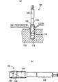
图1是表示作为本发明的一个实施例的螺旋丝锥的图,(a)是正视图,(b)是(a)中的B-B剖面的放大图,(c)是(a)中的C-C剖面的放大图。Fig. 1 is a diagram showing a screw tap as an embodiment of the present invention, (a) is a front view, (b) is an enlarged view of the B-B section in (a), and (c) is a C-C section in (a) Zoom in on the graph.
图2是说明本发明的其它的实施例的图,是与图1的(c)对应的剖视图。Fig. 2 is a diagram illustrating another embodiment of the present invention, and is a cross-sectional view corresponding to (c) of Fig. 1 .
图3是说明分别使用包括本发明品在内的十种试验品No1~No10各两根,进行耐久性试验的结果的图,(a)是说明十种试验品的诸元的图,(b)是表示耐久性试验的试验结果的图。Fig. 3 is the figure that explains the result of durability test using respectively two of ten kinds of test products No1~No10 including the product of the present invention, (a) is a figure illustrating the elements of ten kinds of test products, (b) ) is a graph showing the test results of the durability test.
图4是说明以往的螺旋丝锥的图,(a)是表示将螺纹部拧入螺纹底孔内进行攻丝的状态的剖视图,(b)是表示为了防止切屑的啮入而对完整齿顶部进行了圆筒齿顶清除的螺旋丝锥的正视图。Fig. 4 is a view explaining a conventional spiral tap, (a) is a cross-sectional view showing a state in which the threaded part is screwed into the thread bottom hole for tapping, and (b) is a view showing that the complete tooth crest is tapped to prevent chipping. Front view of a helical tap with cylindrical tip removal.
符号说明Symbol Description
10:螺旋丝锥 16:螺纹部 20:扭转槽 24:完整齿顶部 24a:切入侧齿顶部 24b:刀柄侧齿顶部 26:切削刀 30:倒角(平倒角)32:R倒角(倒角) O:轴心 Hmen:倒角高度 Hneji:螺纹牙高度θ:倒角角度10: Spiral tap 16: Thread part 20: Twist groove 24:
具体实施方式 Detailed ways
本发明的螺旋丝锥是将切屑向刀柄侧排出的螺旋丝锥,具体地说,有对从刀柄侧看向右旋转的旋转驱动沿右扭转的扭转槽设置了切削刀的螺旋丝锥进行切削加工的情况,以及对从刀柄侧看向左旋转的旋转驱动沿左扭转的扭转槽设置了切削刀的螺旋丝锥进行切削加工的情况。The spiral tap of the present invention is a spiral tap that discharges chips to the shank side. Specifically, it is a spiral tap that is provided with a cutting tool in a twisting groove that is twisted to the right when viewed from the shank side. The case of the case, and the case of cutting a spiral tap with a cutting tool for the rotation drive that rotates to the left when viewed from the shank side.
上述螺旋丝锥例如可以使用高速度工具钢(高速钢)、超硬合金等各种工具材料构成,还可以根据需要,涂层TiAlN、TiN、TiCN等硬质覆膜。另外,在水溶性切削油剂、MQL(最少量润滑)或者无切削油剂的干式加工等锋利度不良,切屑容易延伸,进行不规则的运动这样的情况下,本发明的螺旋丝锥能够发挥特别优异的效果,当然也能够在一面充分供给润滑油剂,一面进行丝锥的湿式加工中使用。The above-mentioned spiral tap can be made of various tool materials such as high-speed tool steel (high-speed steel) and cemented carbide, and can be coated with a hard coating such as TiAlN, TiN, TiCN, etc. as necessary. In addition, in the case of water-soluble cutting oil, MQL (Minimum Quantity Lubrication) or dry machining without cutting oil, etc., the sharpness is poor, the chips are easy to extend, and the spiral tap of the present invention can play a role in irregular motion. Particularly excellent effect, of course, can also be used in the wet machining of the tap while fully supplying the lubricating agent.
完整齿顶部中,没有在前倾面设置倒角的切入侧齿顶部若为1个齿顶以下,则不能以高精度引导(先导进给)丝锥,另一方面,若超过了5个齿顶,则容易啮入切屑,容易产生刀豁口、折损,因此,需要为超过1个齿顶并且在5个齿顶以下。Among the complete tooth tops, if there is less than 1 tooth top on the cutting side without chamfering on the rake face, the tap cannot be guided (pilot feed) with high precision. On the other hand, if it exceeds 5 tooth tops , it is easy to bite into chips, and it is easy to produce chipping and breakage. Therefore, it is necessary to have more than 1 tooth top and less than 5 tooth tops.
倒角高度Hmen是以倒角前的切削刀的前端(外周缘)为基准的径向的尺寸。完整齿顶部中的螺纹牙高度Hneji是从螺纹牙的牙根到顶的径向的尺寸,具体地说,用“(丝锥外径-丝锥根径)/2”来表示。这样,若倒角高度Hmen不足螺纹牙高度Hneji的15%,则不能充分获得倒角产生的抑制啮入切屑的作用,提高切削刀强度的效果,另一方面,若超过100%,则在与螺纹底孔(螺纹孔)之间产生间隙反而容易啮入切屑,因此,需要在螺纹牙高度Hneji的15%~100%的范围内。虽然该倒角高度Hmen也可以为一定,但是,也可以是在规定的范围内,在轴向连续或者阶段地变化,或者使多个切削刀的每一个为不同的尺寸。The chamfering height Hmen is a dimension in the radial direction on the basis of the front end (outer peripheral edge) of the cutting blade before chamfering. The thread height Hneji at the top of the complete tooth is a radial dimension from the root of the thread to the top, specifically expressed by "(tap outer diameter - tap root diameter)/2". In this way, if the chamfer height Hmen is less than 15% of the thread height Hneji, the effect of the chamfer to suppress biting chips and improve the strength of the cutting tool cannot be sufficiently obtained. On the other hand, if it exceeds 100%, the Since there is a gap between the threaded bottom holes (threaded holes), it is easy for chips to bite, so it needs to be within the range of 15% to 100% of the thread height Hneji. The chamfer height Hmen may be constant, but may be continuously or stepwise changed in the axial direction within a predetermined range, or may have different dimensions for each of the plurality of cutting blades.
倒角形状为平坦的平倒角或是圆弧形状的R倒角均可。在平倒角的情况下,若在相对于切削刀呈直角的剖面中,相对于将倒角前的切削刀的前端(外周缘)和丝锥轴心O连结的基准线L的倒角角度θ过小,则不能恰当地获得倒角产生的抑制啮入切屑的作用,提高切削刀强度的效果,因此,例如希望在20°程度以上。另外,若倒角角度θ过大,则倒角和前倾面之间的角度小,容易卡住切屑,因此,例如希望在60°程度以下。虽然该倒角角度θ可以为一定,但是,也可以是在规定的范围内,在轴向连续或者阶段地变化,或者使多个切削刀的每一个为不同的角度。The chamfer shape can be a flat chamfer or an arc-shaped R chamfer. In the case of flat chamfering, the chamfering angle θ with respect to the reference line L connecting the tip (outer peripheral edge) of the cutting tool before chamfering and the tap axis O in a cross section at right angles to the cutting tool If the angle is too small, the effect of suppressing the biting of chips by chamfering and improving the strength of the cutting tool cannot be properly obtained. Therefore, for example, it is preferably about 20° or more. In addition, if the chamfer angle θ is too large, the angle between the chamfer and the rake surface becomes small, and chips are likely to be caught, so it is preferably about 60° or less, for example. Although the chamfering angle θ may be constant, it may be continuously or stepwise changed in the axial direction within a predetermined range, or may be different for each of the plurality of cutting blades.
R倒角虽然例如是在相对于切削刀呈直角的截面中,相对于前倾面以及螺纹牙的顶平滑地被连接的大致一定半径的圆弧形状,但是也可以是曲率根据加工的情况等连续地变化的圆弧形状。The R chamfer is, for example, a circular arc shape with a substantially constant radius that is smoothly connected to the rake surface and the top of the thread thread in a cross section at a right angle to the cutting blade, but the curvature may be changed depending on the machining situation, etc. Continuously changing arc shape.
虽然希望在完整齿顶部的螺纹牙设置偏心释放槽等空刀槽,但是也可以采用没有空刀槽的一定直径尺寸的螺纹牙。即,本发明中只要在完整齿顶部中的刀柄侧齿顶部的切削刀的前倾面设置倒角即可,对螺纹牙的空刀槽而言,包括其有无在内,可以是各种样态,例如,也可以对螺纹牙的顶附近进行齿顶清除成圆筒形状。Although it is desirable to set empty slits such as eccentric relief grooves on the thread teeth at the top of the complete tooth, it is also possible to use thread teeth of a certain diameter without empty slits. That is, in the present invention, it is only necessary to provide chamfering on the rake face of the cutting blade on the shank side tooth top among the complete tooth tops, and the empty sipe of the thread thread, including its presence or absence, may be various In other ways, for example, it is also possible to remove the top of the tooth near the top of the thread into a cylindrical shape.
设置在螺纹部的扭转槽的扭转角从切屑的排出性的观点来看,希望在例如15°~50°程度的范围内。另外,切削刀的数量根据被切削材质、丝锥尺寸,例如为两片~六片程度合适。The twist angle of the twist grooves provided in the thread portion is preferably within a range of, for example, about 15° to 50° from the viewpoint of chip discharge performance. In addition, the number of cutting blades is suitable, for example, from about two to six depending on the material to be cut and the size of the tap.
实施例Example
下面,参照附图,详细说明本发明的实施例。Hereinafter, embodiments of the present invention will be described in detail with reference to the drawings.
图1是表示作为本发明的一个实施例的三片刀的螺旋丝锥10的图,(a)是从与轴心O呈直角方向看到的正视图,(b)是(a)中的B-B剖面的放大图,(c)是(a)中的C-C剖面的放大图。该螺旋丝锥10在同一轴心O上一体地依次具备刀柄12、颈部14以及螺纹部16,在螺纹部16设置与欲加工的阴螺纹对应的螺纹槽形状的阳螺纹,同时,以将该阳螺纹分断的方式设置三条扭转槽20。螺纹部16具备在轴向将阳螺纹的螺纹牙18锥状地除去的前端侧的切入部22和与该切入部22连续地设置的具有完整的螺纹牙18的完整齿顶部24,在与上述扭转槽20的棱角线部分形成切削刀26。扭转槽20为右扭转,其扭转角在15°~50°程度的范围内,例如为40°程度,螺旋丝锥10从刀柄12侧看右旋转地被旋转驱动,并且,例如通过从前端侧拧入上述图4的被加工物110的螺纹底孔112内,在该螺纹底孔112的内周面切屑加工阴螺纹,同时,通过扭转槽20,将切屑向刀柄12侧排出。Fig. 1 is a diagram showing a
在上述完整齿顶部24,残留有与切入部22连续的前端侧的超过1个齿顶并且5个齿顶以下的切入侧齿顶部24a,在与之相比位于刀柄12侧的刀柄侧齿顶部24b的切削刀26的前倾面(扭转槽20的一部分)上,设置随着朝着螺纹牙18的顶,即,外周侧而向周方向(跟部侧)后退的倒角30。图1的(b)是没有设置倒角30的切入侧齿顶部24a的剖视图,图1的(c)是设置了倒角30的刀柄侧齿顶部24b的剖视图,倒角30的倒角高度Hmen在完整齿顶部24的螺纹牙高度Hneji的15%~100%的范围内,例如在50%的程度。倒角高度Hmen是以倒角前的切削刀26的前端(外周缘)为基准的径向的尺寸,螺纹牙高度Henji是从螺纹牙18的牙根到顶的径向的尺寸,具体地说,是“(丝锥外径-丝锥根径)/2”。In the above-mentioned
另外,上述倒角30是平坦的平倒角,相对于将倒角前的切削刀26的前端(外周缘)和丝锥轴心O连结的基准线L的倒角角度θ在20°~60°的范围内,例如为45°的程度。虽然该倒角角度θ在图1的(c)中相对于轴心O显示出直角的截面,但是,严紧地说,按照相对于沿扭转槽20形成的切削刀26呈直角的截面的角度,该倒角角度θ被确定在20°~60°的范围内。In addition, the above-mentioned
另外,上述倒角高度Hmen以及倒角角度θ在本实施例中,都是在刀柄侧齿顶部24b的整个区域为一定的尺寸以及一定的角度。另外,本实施例的螺旋丝锥10由高速度工具钢(粉末高速钢)构成,同时,在螺纹部16涂层TiCN的硬质覆膜。另外,完整齿顶部24的螺纹牙18虽然存在着在图1的(b)、(c)中一直到跟部直径尺寸为一定,没有空刀槽的情况,但是,根据需要,设置偏心释放槽等空刀槽。在切入部22的螺纹牙18上设置规定的空刀槽。In addition, the above-mentioned chamfering height Hmen and chamfering angle θ have a constant size and a constant angle over the entire area of the shank-
根据这样的本发明的螺旋丝锥10,因为在螺纹部16的完整齿顶部24中,在位于刀柄12侧的刀柄侧齿顶部24b的切削刀26的前倾面,以螺纹牙高度Hneji的15%~100%的范围内的倒角高度Hmen设置倒角30,所以,容易沿该倒角30向外周侧推出切屑,抑制切屑啮入本身,同时,由于通过倒角30提高了切屑刀26的强度,因此,有效地防止了切屑的啮入造成的刀豁口、折损,耐久性(寿命)提高。According to such a
另外,螺纹部16的完整齿顶部24中与切入部22连续的前端侧的超过1个齿顶并且5个齿顶以下的切入侧齿顶部24a具有原来那样的完整的螺纹牙形状,同时,设置了倒角30的刀柄侧齿顶部24b除切削刀26部分以外,也是原来的螺纹牙形状,因此,与从有效直径附近将顶部分齿顶清除成圆筒形状的情况相比,在完整齿顶部24的整个区域得到优异的引导作用(先导进给),能够以高的加工精度切削加工阴螺纹。In addition, among the complete tooth tops 24 of the threaded
另外,在本实施例中,虽然作为倒角30设置了平坦的平倒角,但是,因为该倒角角度θ在20°~60°的范围内,所以,能够恰当地得到倒角30产生的抑制啮入切屑的作用、提高切削刀强度的效果,耐久性提高。In addition, in this embodiment, although a flat chamfer is provided as the
另外,在上述实施例中,虽然作为倒角30设置了平坦的平倒角,但是,也可以如图2所示,设置R倒角32。该R倒角32在相对于沿扭转槽20形成的切削刀26呈直角的截面中,都是相对于前倾面(扭转槽20)以及螺纹牙18的顶以平滑地连接的方式设置,例如,由半径大致一定的圆弧构成。In addition, in the above-mentioned embodiment, although the
图3是说明分别准备包括本发明品在内的十种试验品No1~No10各两根,按照下述的加工条件进行攻丝,并对耐久性进行调查的结果的图,(a)是说明十种试验品No1~No10的诸元的图。另外,(b)是以有无刀豁口或者折损来表示对耐久性进行调查的试验结果的图。Fig. 3 is a diagram explaining the results of investigating the durability by preparing two of ten kinds of test products No1 to No10 including the product of the present invention, tapping them according to the following processing conditions, and (a) is explanatory Diagrams of elements of ten test items No1 to No10. In addition, (b) is a figure which shows the test result which investigated durability with the presence or absence of a cut or breakage.
(加工条件)(Processing conditions)
·尺寸:M8×1.25·Size: M8×1.25
·被切削材料:SUS304·Material to be cut: SUS304
·切削速度:8m/min·Cutting speed: 8m/min
·螺纹底孔形状:通孔、Φ6.8×25mm·Thread bottom hole shape: through hole, Φ6.8×25mm
·螺纹有效长度:16mm(工具直径的两倍)Effective thread length: 16mm (twice the diameter of the tool)
·切削油剂:水溶性切削油剂Cutting oil: water-soluble cutting oil
·使用机械:卧式加工中心·Used machine: horizontal machining center
各试验品No1~No10的基本形状与上述实施例的螺旋丝锥10相同,在图3的(a)中标注了下划线的部分是与本发明不同的项目。即,试验品No1是没有设置上述倒角30或者32的以往品。试验品No2是切入侧齿顶部24a的齿顶数为4齿顶,在刀柄侧齿顶部24b中,从有效直径开始,顶侧的部分被齿顶清除成圆筒形状的上述专利文献2记载的以往品。试验品No3是切入侧齿顶部24a的齿顶数为4齿顶,倒角角度θ=45°,倒角高度Hmen为螺纹牙高度Hneji的10%的过小的比较品。试验品No4~No8均为本发明品,切入侧齿顶部24a的齿顶数为1.5个齿顶或者4个齿顶,倒角角度θ为30°或45°或者圆弧形状的R倒角,倒角高度Hmen为螺纹牙高度Hneji的20%、50%或100%。试验品No9是切入侧齿顶部24a的齿顶数为4个齿顶,倒角角度θ=45°,但倒角高度Hmen为螺纹牙高度Hneji的1.2倍的过大的比较品。试验品No10是倒角角度θ=45°,倒角高度Hmen为螺纹牙高度Hneji的50%,但切入侧齿顶部24a的齿顶数为6个齿顶的过多的比较品。The basic shape of each test product No1-No10 is the same as the
从图3的(b)的试验结果可以看出,根据本发明的试验品No4~No8,都能进行900个以上的攻丝,特别是试验品No5~No7在加工了1000个的阶段,仍能够继续进行攻丝。与此相对,试验品No1的以往品多的也就是在56个折损。在有效直径部分进行圆筒状齿顶清除的试验品No2多的在598个折损,虽然与试验品No1相比耐久性大幅提高,但是与本发明品(试验品No5~No8)相比,为一半的程度。另外,试验品No3的比较品多的在108个折损,不能充分获得倒角30产生的提高耐久性的效果。试验品No9、No10的比较品多的分别在608个、750个折损,虽然得到了大致的提高耐久性的效果,但是,与试验品No2的以往品相比没有太大的差别。From the test result of Fig. 3 (b), it can be seen that according to the test products No4-No8 of the present invention, more than 900 tappings can be carried out, and especially the test products No5-No7 are still at the stage of processing 1000 pieces. Able to continue tapping. On the other hand, the conventional product of test product No. 1 had 56 breakages. Test product No. 2, which has cylindrical addendum cleaning in the effective diameter part, has 598 breakages. Compared with test product No. 1, the durability is greatly improved, but compared with the products of the present invention (test products No. 5 to No. 8), to half the extent. In addition, the comparative product of the test product No. 3 had many breakages at 108 points, and the effect of improving the durability by the
上面,根据附图,详细说明了本发明的实施例,但这仅仅是一个实施方式,本发明能够在根据本领域技术人员的知识进行了各种变更,改进的基础的方式上进行实施。The embodiments of the present invention have been described above in detail with reference to the drawings, but this is only one embodiment, and the present invention can be implemented in various modifications and improvements based on the knowledge of those skilled in the art.
产业上利用的可能性Possibility of industrial use
本发明的螺旋丝锥,因为在螺纹部的完整齿顶部中,在位于刀柄侧的刀柄侧齿顶部的切削刀的前倾面,螺纹牙高度Hneji的15%~100%的范围内的倒角高度Hmen设置倒角,所以,容易沿该倒角向外周侧推出切屑,抑制切屑啮入本身,同时,由于通过倒角,提高了切屑刀的强度,因此,有效地防止了切屑的啮入造成的刀豁口、折损,能够得到优异的耐久性,适合用于阴螺纹的攻丝加工。In the spiral tap of the present invention, in the complete tooth top of the thread portion, the rake surface of the cutting blade located on the shank side tooth top on the shank side has a reverse in the range of 15% to 100% of the thread tooth height Hneji. The angle height Hmen is provided with a chamfer, so it is easy to push out the chip to the outer peripheral side along the chamfer, and the chip bite itself is suppressed. At the same time, since the strength of the chip knife is improved by the chamfer, the chip bite is effectively prevented. Excellent durability can be obtained due to chipping and breakage caused by the knife, and it is suitable for tapping of female threads.
Claims (5)
Applications Claiming Priority (1)
| Application Number | Priority Date | Filing Date | Title |
|---|---|---|---|
| PCT/JP2006/325210 WO2008075402A1 (en) | 2006-12-18 | 2006-12-18 | Spiral tap |
Publications (1)
| Publication Number | Publication Date |
|---|---|
| CN101563180A true CN101563180A (en) | 2009-10-21 |
Family
ID=39536041
Family Applications (1)
| Application Number | Title | Priority Date | Filing Date |
|---|---|---|---|
| CNA2006800566840A Pending CN101563180A (en) | 2006-12-18 | 2006-12-18 | Spiral tap |
Country Status (6)
| Country | Link |
|---|---|
| US (1) | US20090317203A1 (en) |
| JP (1) | JPWO2008075402A1 (en) |
| KR (1) | KR20090094005A (en) |
| CN (1) | CN101563180A (en) |
| DE (1) | DE112006004174T5 (en) |
| WO (1) | WO2008075402A1 (en) |
Cited By (2)
| Publication number | Priority date | Publication date | Assignee | Title |
|---|---|---|---|---|
| CN103909310A (en) * | 2014-04-08 | 2014-07-09 | 浙江美克工具有限公司 | Screw tap |
| CN105209202A (en) * | 2013-05-24 | 2015-12-30 | Osg株式会社 | Taps for Thread Cutting |
Families Citing this family (7)
| Publication number | Priority date | Publication date | Assignee | Title |
|---|---|---|---|---|
| DE112008004051T5 (en) * | 2008-10-27 | 2012-05-03 | Osg Corp. | Spiral tap |
| CN102438786A (en) * | 2009-02-20 | 2012-05-02 | Osg株式会社 | tap with drill bit |
| CN102581395A (en) * | 2012-03-21 | 2012-07-18 | 锑玛(苏州)精密工具有限公司 | Screw tap for high hardness steel |
| CN102554373A (en) * | 2012-03-21 | 2012-07-11 | 锑玛(苏州)精密工具有限公司 | Tool cutting edge inclination screw tap |
| CN103990869B (en) * | 2014-06-12 | 2016-03-30 | 航天精工股份有限公司 | Big L/D ratio titanium alloy screw tap for tapping |
| US9839984B2 (en) | 2014-08-14 | 2017-12-12 | Kennametal Inc. | Method of making a cutting tap with a correction grind |
| CN112356313B (en) * | 2020-09-29 | 2022-07-29 | 航天材料及工艺研究所 | A low-damage turning method for fine internal threads of ceramic matrix composites |
Family Cites Families (12)
| Publication number | Priority date | Publication date | Assignee | Title |
|---|---|---|---|---|
| US1613224A (en) * | 1925-03-06 | 1927-01-04 | Huron Mfg Co | Tap |
| US1826323A (en) * | 1930-02-19 | 1931-10-06 | Mueller Co | Combined drill, reamer, and tap |
| US3131407A (en) * | 1962-03-08 | 1964-05-05 | Glynton M Roberts | Thread swaging tap |
| JPH0475186A (en) | 1990-07-17 | 1992-03-10 | Mitsubishi Electric Corp | Character reader |
| JP2555470B2 (en) * | 1990-07-18 | 1996-11-20 | オーエスジー株式会社 | Twist groove tap |
| JP2603939Y2 (en) * | 1993-07-21 | 2000-04-04 | オーエスジー株式会社 | Tap for thread cutting |
| WO1999003631A1 (en) * | 1996-02-09 | 1999-01-28 | Osg Corporation | Cold forming tap with inside diameter finish blade and method of manufacturing same |
| JP2813173B2 (en) | 1996-10-25 | 1998-10-22 | 株式会社彌満和製作所 | Spiral tap |
| JPH10286723A (en) * | 1997-04-09 | 1998-10-27 | Nissan Motor Co Ltd | Tap for thread cutting |
| SE522664C2 (en) * | 2001-04-30 | 2004-02-24 | Sandvik Ab | Cutting thread pin and procedure for its manufacture |
| JP4711605B2 (en) * | 2003-05-12 | 2011-06-29 | 富士電機株式会社 | Thread cutting tap and its manufacturing method, tapping method and apparatus |
| DE10332930A1 (en) * | 2003-07-19 | 2005-02-03 | Sandvik Ab | screw tap |
-
2006
- 2006-12-18 WO PCT/JP2006/325210 patent/WO2008075402A1/en not_active Ceased
- 2006-12-18 KR KR1020097013221A patent/KR20090094005A/en not_active Ceased
- 2006-12-18 CN CNA2006800566840A patent/CN101563180A/en active Pending
- 2006-12-18 US US12/448,276 patent/US20090317203A1/en not_active Abandoned
- 2006-12-18 JP JP2008549997A patent/JPWO2008075402A1/en active Pending
- 2006-12-18 DE DE112006004174T patent/DE112006004174T5/en not_active Withdrawn
Cited By (3)
| Publication number | Priority date | Publication date | Assignee | Title |
|---|---|---|---|---|
| CN105209202A (en) * | 2013-05-24 | 2015-12-30 | Osg株式会社 | Taps for Thread Cutting |
| US9737944B2 (en) | 2013-05-24 | 2017-08-22 | Osg Corporation | Thread-cutting tap |
| CN103909310A (en) * | 2014-04-08 | 2014-07-09 | 浙江美克工具有限公司 | Screw tap |
Also Published As
| Publication number | Publication date |
|---|---|
| KR20090094005A (en) | 2009-09-02 |
| JPWO2008075402A1 (en) | 2010-04-02 |
| DE112006004174T5 (en) | 2009-10-29 |
| WO2008075402A1 (en) | 2008-06-26 |
| US20090317203A1 (en) | 2009-12-24 |
Similar Documents
| Publication | Publication Date | Title |
|---|---|---|
| CN101400469B (en) | Spiral tap | |
| EP1383623B1 (en) | A thread cutting tap and a method of its manufacture | |
| US20070056424A2 (en) | Radius end mill | |
| CN107000080A (en) | Radius end mill, ball end mill and slotting cutter | |
| CN107107212A (en) | Formed end mill | |
| CN100379514C (en) | thread cutting tool | |
| JP2008272856A (en) | Spiral tap | |
| CN101563180A (en) | Spiral tap | |
| KR20110073607A (en) | Spiral Tab | |
| JP5756562B2 (en) | Spiral tap | |
| JP5301452B2 (en) | Spiral tap and manufacturing method thereof | |
| WO2017154121A1 (en) | Taper thread-cutting spiral pipe tap | |
| KR101849445B1 (en) | Thread-cutting tap | |
| JP6692932B2 (en) | Thread milling | |
| JP2008036722A (en) | Radius end mill | |
| JP5237659B2 (en) | Cutting tap | |
| WO2017094152A1 (en) | Tapered pipe thread-machining spiral tap | |
| JP2019217577A (en) | Cutting tap | |
| JP2011161579A (en) | Cutting tap | |
| JP2025024849A (en) | Interrupt Tap | |
| JP2005271167A (en) | End mill | |
| JP2024140513A (en) | Spiral Tap | |
| WO2025186919A1 (en) | Point tap | |
| KR20090012300A (en) | Spiral Tab | |
| JP2004223633A (en) | Small diameter ball end mill |
Legal Events
| Date | Code | Title | Description |
|---|---|---|---|
| C06 | Publication | ||
| PB01 | Publication | ||
| C10 | Entry into substantive examination | ||
| SE01 | Entry into force of request for substantive examination | ||
| C02 | Deemed withdrawal of patent application after publication (patent law 2001) | ||
| WD01 | Invention patent application deemed withdrawn after publication |
Open date: 20091021 |