CN101550903A - Rack type wind energy device - Google Patents
Rack type wind energy device Download PDFInfo
- Publication number
- CN101550903A CN101550903A CNA2008100908177A CN200810090817A CN101550903A CN 101550903 A CN101550903 A CN 101550903A CN A2008100908177 A CNA2008100908177 A CN A2008100908177A CN 200810090817 A CN200810090817 A CN 200810090817A CN 101550903 A CN101550903 A CN 101550903A
- Authority
- CN
- China
- Prior art keywords
- wind
- rack
- cloth
- racks
- wind energy
- Prior art date
- Legal status (The legal status is an assumption and is not a legal conclusion. Google has not performed a legal analysis and makes no representation as to the accuracy of the status listed.)
- Pending
Links
- 239000000463 material Substances 0.000 claims abstract description 10
- 239000004744 fabric Substances 0.000 claims description 42
- 230000006855 networking Effects 0.000 claims description 5
- 238000004519 manufacturing process Methods 0.000 claims description 4
- 239000004677 Nylon Substances 0.000 claims description 3
- 229920001778 nylon Polymers 0.000 claims description 3
- 239000002985 plastic film Substances 0.000 claims description 3
- 229920006255 plastic film Polymers 0.000 claims description 3
- 238000007665 sagging Methods 0.000 claims description 3
- 239000000126 substance Substances 0.000 claims description 3
- 238000010248 power generation Methods 0.000 abstract 1
- 230000009286 beneficial effect Effects 0.000 description 1
- 238000004140 cleaning Methods 0.000 description 1
- 230000005611 electricity Effects 0.000 description 1
- 238000005516 engineering process Methods 0.000 description 1
- 238000005286 illumination Methods 0.000 description 1
- 230000008676 import Effects 0.000 description 1
- 239000003562 lightweight material Substances 0.000 description 1
- 238000000034 method Methods 0.000 description 1
Images
Classifications
-
- Y—GENERAL TAGGING OF NEW TECHNOLOGICAL DEVELOPMENTS; GENERAL TAGGING OF CROSS-SECTIONAL TECHNOLOGIES SPANNING OVER SEVERAL SECTIONS OF THE IPC; TECHNICAL SUBJECTS COVERED BY FORMER USPC CROSS-REFERENCE ART COLLECTIONS [XRACs] AND DIGESTS
- Y02—TECHNOLOGIES OR APPLICATIONS FOR MITIGATION OR ADAPTATION AGAINST CLIMATE CHANGE
- Y02E—REDUCTION OF GREENHOUSE GAS [GHG] EMISSIONS, RELATED TO ENERGY GENERATION, TRANSMISSION OR DISTRIBUTION
- Y02E10/00—Energy generation through renewable energy sources
- Y02E10/70—Wind energy
- Y02E10/74—Wind turbines with rotation axis perpendicular to the wind direction
-
- Y—GENERAL TAGGING OF NEW TECHNOLOGICAL DEVELOPMENTS; GENERAL TAGGING OF CROSS-SECTIONAL TECHNOLOGIES SPANNING OVER SEVERAL SECTIONS OF THE IPC; TECHNICAL SUBJECTS COVERED BY FORMER USPC CROSS-REFERENCE ART COLLECTIONS [XRACs] AND DIGESTS
- Y02—TECHNOLOGIES OR APPLICATIONS FOR MITIGATION OR ADAPTATION AGAINST CLIMATE CHANGE
- Y02P—CLIMATE CHANGE MITIGATION TECHNOLOGIES IN THE PRODUCTION OR PROCESSING OF GOODS
- Y02P70/00—Climate change mitigation technologies in the production process for final industrial or consumer products
- Y02P70/50—Manufacturing or production processes characterised by the final manufactured product
Landscapes
- Structures Of Non-Positive Displacement Pumps (AREA)
Abstract
The invention relates to a rack type wind energy device which is mainly used for wind energy power generation and wind energy utilization and is a vertical shaft wind energy device. The wind energy device comprises racks, cloths, an intermediate shaft, and the like, and utilizes the principle that the racks and the cloths can wrap wind and can be blown as well as lead wind to smoothly pass through. One side of each of four same square racks is arranged on the same shaft in parallel, every two adjacent racks form an angle of 90 degrees; and the upper ends of a plurality of cloths are in parallel fixed in the front of the racks according to the order of the rotation of the racks and are sequentially overspread. When wind blows from any direction, the resistance to wind occurs in contrast to lead the rotation for driving equipment of a generator, and the like to operate because of the function of the four racks and the cloths. The rack type wind energy device has large contact area with wind, large rotation power, simple structure, low cost and small occupation area, can rotate by gentle breeze without wind direction tail fin, can be made of common light materials, can be massively made, and can be made into a series of dynamic advisement and sight when in operation because of the integral fan shape.
Description
Technical field
The invention relates to the wind energy aspect, be mainly used in wind energy power and Wind Power Utilization.
Background technique
At present, as a kind of energy of green cleaning, the main collection wind devices of Wind Power Utilization is a propeller type, and mostly power is little for its middle-size and small-size family expenses wind energy plant, and can only keep general illumination and small-power electrical equipment.And because the utilization and the technology of wind are limit, all there is certain requirement large-scale wind energy power field to the size and the addressing of wind-force.And many equipment all need import, and cost is higher.These are all restricting the development of China's wind-powered electricity generation.Though so China has abundant wind resource but to fail well to be utilized and develop.
Summary of the invention
The present invention is the vertical shaft wind energy plant, is made up of rack, cloth, axis etc.; The principle of mainly utilizing rack and cloth can keep watch and catch and can be blown up and make it to pass through smoothly; Make contacting of rack energy maximum area on the one hand, increase resistance, can dissolve resistance on the other hand again to greatest extent, make corresponding two racks reach maximum value the resistance difference of wind to wind to wind with wind.
This device is made of the identical square rack of four fans, also three fans or more than four fans, rack is made up of frame and middle screen cloth, and frame is made by light weight, material that intensity is good; Mesh requires to try one's best and sparsely can catch fully till the cloth again to reduce the resistance to wind, is made by the wire netting of light weight or durable materials such as nylon net.Per two fan racks are one group, parallel connection, and the attachment portion is rotating shaft.On rack, the cloth on one of them rack is installed in its front with the upper end secured in parallel of each cloth, and the cloth on another rack is installed in its back, till being covered with successively; Mode is installed another networking frame like this, and the axis with four fan racks is installed together then, and every two adjacent racks at an angle of 90.Materials such as chemical fabric that also available other light weight softness of cloth can be blown afloat easily by wind or plastic film replace, and cloth is square, and area should be equal to or less than 1/4th of rack, is advisable to be no more than 1 square metre.
This device is installed in the place of wind, when wind in any direction blows, always having two wire sides facings the wind, the cloth of one of them wire side is blocked mesh by the wind exhibition fully in its front, and the cloth of another corresponding wire side is blown up in its back with it, wind is passed through smoothly, remaining two fan racks are state with the wind, cloth is sagging naturally and since two wire sides to the resistance difference of wind, block mesh one in the face of the resistance of wind big, the another side that is blown up cloth is little to the resistance of wind, so whole device is promoted by wind, causes rotation, drive equipment operations such as generator.
The beneficial effect of this device is: 1, the area of contact of this device and wind is big, and therefore the power of rotation is also big, but small-sized household also can maximize and manufacture.2, breeze start-up only needs 2-3 level wind can cause rotation, and also can rotating speed when blast occurring too not fast, and rotating speed is even.3, need not the wind direction empennage, no matter all can all can counterclockwise clockwise by fixing direction rotation from the wind of which direction.4, device is simple, and common lightweight material can be manufactured, and cost is low, and floor space is little.5, because the whole shape of covering of the fan also can be manufactured a series of dynamic advertisements in generating, increase the people's attention degree.For grade attractive in appearance special requirement, also the various abnormity of covering of the fan system can be equipped with various patterns and make it to become beautiful view one.
Description of drawings
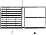
Fig. 1: manufacture two identical square racks, parallel linking to each other, middle is rotating shaft.The upper end of cloth is fixed on the rack, and the A rack will be contained in cloth its front, and the B rack will be contained in cloth its back, till being covered with.
Fig. 2: manufacture another networking frame C, D according to the mode of Fig. 1.
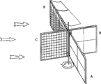
Fig. 3: the axis of two networking framves is installed together.Every fan rack angle is 90 °.When wind blows from left to right, wherein the cloth of A net, is blocked mesh by the wind exhibition fully in the front of net, has strengthened the resistance to wind; The cloth of B net is blown up in the back of rack, and wind passes through from rack, has reduced the resistance to wind; C net D net is in that the state cloth is sagging naturally with the wind; Final rack is promoted by wind, with this rotation that circulates, drives equipment operations such as generator.
Embodiment
This device is the vertical shaft wind energy plant, constitute by the identical square rack of four fans, cloth, axis etc., wherein rack is made up of frame and middle screen cloth, net frame light weight, the material that intensity is good are made, and the mesh sparse resistance that reduces to greatest extent wind that requires to try one's best can catch again till cloth makes it to pass fully, material is made by the wire netting of lightweight or durable nylon net etc., wherein per two fan racks are one group, parallel connection, and the attachment portion is rotating shaft.The upper end secured in parallel of each cloth on rack, till being covered with successively.Cloth on one of them rack is installed in its front, and the cloth on another rack is installed in its back, till being covered with successively; Materials such as chemical fabric that also available other light weight softness of cloth can be blown afloat easily by wind or plastic film replace, and mode is installed another networking frame like this, and the axis with four fan racks are installed together then, and every two adjacent racks at an angle of 90.When wind in any direction blows, because four fan racks contrast occurs to the resistance of wind,, cause rotation so promoted by wind, drive equipment operations such as generator thus.
Claims (6)
1, a kind of vertical shaft wind energy plant is mainly used in wind energy power and Wind Power Utilization etc., is made of rack, cloth, axis etc., wherein rack is square totally four fans, is made up of frame and middle screen cloth, and per two fan racks are one group, parallel connection, attachment portion are rotating shaft; With the upper end secured in parallel of cloth on rack, till being covered with successively; Cloth on one of them rack is installed in its front, cloth on another rack is installed in its back, mode is installed another networking frame like this, axis with four fan racks is installed together then, when wind in any direction blows, always have two wire sides and facing the wind, the cloth of one of them wire side is blocked mesh by the wind exhibition fully in the front of rack, and the cloth of another corresponding wire side is blown up in the back of rack with it, and wind is passed through smoothly; Remaining two fan racks are in state with the wind, and cloth is sagging naturally, owing to two racks contrast occurs to the resistance of wind, cause rotation, and sense of rotation can be adjusted, and drives equipment operations such as generator according to this.
According to right 1 described vertical shaft wind energy plant, it is characterized in that 2, described cardinal principle is a principle of utilizing rack and cloth can keep watch and catch and can be blown up and make it to pass through smoothly; Make contacting of rack energy maximum area on the one hand, increase resistance wind with wind; Can dissolve resistance on the other hand again to greatest extent, make two relative racks reach maximum value the resistance difference of wind to wind.
According to right 1 described vertical shaft wind energy plant, it is characterized in that 3, described four fan square racks also can be three fans or more than four fans, the area of rack and big or small identical.
According to right 1 described vertical shaft wind energy plant, it is characterized in that 4, described rack available quality material light, that intensity is good is made; Middle screen cloth can be made with the materials such as the also available nylon net of wire netting of lightweight; Mesh requires to try one's best sparse in to reduce the resistance to wind to greatest extent, can catch till the cloth fully again.
According to right 1 described vertical shaft wind energy plant, it is characterized in that 5, described cloth can be made with materials such as the chemical fabric that can be blown afloat easily by wind of softness or plastic films; Cloth is square, and area should be equal to or less than 1/4th of rack, is advisable to be no more than 1 square metre.
According to right 1 described vertical shaft wind energy plant, it is characterized in that 6, described rack covering of the fan is put in order shape, in operation, also can manufacture a series of dynamic advertisements, increase the people's attention degree; For grade attractive in appearance special requirement, also covering of the fan can be made various different shapes, be equipped with various patterns and make it to become beautiful view one.
Priority Applications (1)
| Application Number | Priority Date | Filing Date | Title |
|---|---|---|---|
| CNA2008100908177A CN101550903A (en) | 2008-04-05 | 2008-04-05 | Rack type wind energy device |
Applications Claiming Priority (1)
| Application Number | Priority Date | Filing Date | Title |
|---|---|---|---|
| CNA2008100908177A CN101550903A (en) | 2008-04-05 | 2008-04-05 | Rack type wind energy device |
Publications (1)
| Publication Number | Publication Date |
|---|---|
| CN101550903A true CN101550903A (en) | 2009-10-07 |
Family
ID=41155340
Family Applications (1)
| Application Number | Title | Priority Date | Filing Date |
|---|---|---|---|
| CNA2008100908177A Pending CN101550903A (en) | 2008-04-05 | 2008-04-05 | Rack type wind energy device |
Country Status (1)
| Country | Link |
|---|---|
| CN (1) | CN101550903A (en) |
Cited By (7)
| Publication number | Priority date | Publication date | Assignee | Title |
|---|---|---|---|---|
| GB2475552A (en) * | 2009-11-23 | 2011-05-25 | Rajendranath Balkee | Flapping wind generator |
| CN102086840A (en) * | 2009-12-04 | 2011-06-08 | 武汉光跃科技有限公司 | Blade device of vertical type resistance difference type wind driven generator |
| CN102943745A (en) * | 2012-12-07 | 2013-02-27 | 桂林理工大学 | Vertical-shaft grid curtain type small wind driven generator |
| CN103629053A (en) * | 2013-12-17 | 2014-03-12 | 中国矿业大学 | Bionic vertical-axis wind turbine |
| CN108457796A (en) * | 2018-05-15 | 2018-08-28 | 李婉玉 | A kind of horizontal rotation breeze wind wind-energy collecting device with flap valve structure |
| CN115506950A (en) * | 2022-10-12 | 2022-12-23 | 武汉云太极科技有限公司 | Open and close vertical axis fluid wheel power generation device |
| CN118979845A (en) * | 2024-10-13 | 2024-11-19 | 欧德曼(徐州)机械科技有限公司 | Flexible composite blade vertical axis wind turbine |
-
2008
- 2008-04-05 CN CNA2008100908177A patent/CN101550903A/en active Pending
Cited By (8)
| Publication number | Priority date | Publication date | Assignee | Title |
|---|---|---|---|---|
| GB2475552A (en) * | 2009-11-23 | 2011-05-25 | Rajendranath Balkee | Flapping wind generator |
| CN102086840A (en) * | 2009-12-04 | 2011-06-08 | 武汉光跃科技有限公司 | Blade device of vertical type resistance difference type wind driven generator |
| CN102943745A (en) * | 2012-12-07 | 2013-02-27 | 桂林理工大学 | Vertical-shaft grid curtain type small wind driven generator |
| CN103629053A (en) * | 2013-12-17 | 2014-03-12 | 中国矿业大学 | Bionic vertical-axis wind turbine |
| CN108457796A (en) * | 2018-05-15 | 2018-08-28 | 李婉玉 | A kind of horizontal rotation breeze wind wind-energy collecting device with flap valve structure |
| CN108457796B (en) * | 2018-05-15 | 2019-08-23 | 李婉玉 | A kind of horizontal rotation breeze wind wind-energy collecting device with flap valve structure |
| CN115506950A (en) * | 2022-10-12 | 2022-12-23 | 武汉云太极科技有限公司 | Open and close vertical axis fluid wheel power generation device |
| CN118979845A (en) * | 2024-10-13 | 2024-11-19 | 欧德曼(徐州)机械科技有限公司 | Flexible composite blade vertical axis wind turbine |
Similar Documents
| Publication | Publication Date | Title |
|---|---|---|
| CN101550903A (en) | Rack type wind energy device | |
| EP2311022B1 (en) | Solar power generation display assembly and method for providing same | |
| CN102290003B (en) | Photovoltaic, sunshade, display integral LED display screen | |
| CN205154497U (en) | Wind blade device | |
| CN202487092U (en) | 360-degree spherical LED display | |
| CN201765770U (en) | Rotatable LED display screen | |
| CN202217456U (en) | Light emitting diode (LED) flexible hung display screen | |
| US10756596B2 (en) | Fluid-powered generator | |
| KR20140028282A (en) | Led electric lighting board | |
| KR100936503B1 (en) | Segmental twisting wind generation system having booster blades | |
| WO2012005703A1 (en) | Rotating motion power generation by harnessing high altitude wind | |
| KR20140011876A (en) | A windmill having variable blades | |
| CN201810484U (en) | Vertical wind power generator with wind deflector | |
| JP2011196366A (en) | Wind power generator with variable wind-turbine blades | |
| CN209369986U (en) | Hang curtain windmill structure | |
| CN215979685U (en) | Automatic escalator type paddle-free wind power generation system | |
| CN210637187U (en) | Landscape type power generation device | |
| WO2019195562A1 (en) | Regenerative and sustainable energy structures | |
| CN105221338B (en) | Wind generator system | |
| CN101800491A (en) | Photovoltaic generating system and device | |
| TWI282531B (en) | A net structure for a large electronic screen | |
| CN115788777A (en) | Solar and wind power generation fence | |
| CN200959194Y (en) | Mesh structure of large electronic display screens | |
| CN210378226U (en) | Magic cube type LED display screen | |
| US9309864B2 (en) | Transverse axis turbine with controllable display |
Legal Events
| Date | Code | Title | Description |
|---|---|---|---|
| C06 | Publication | ||
| PB01 | Publication | ||
| C10 | Entry into substantive examination | ||
| SE01 | Entry into force of request for substantive examination | ||
| C02 | Deemed withdrawal of patent application after publication (patent law 2001) | ||
| WD01 | Invention patent application deemed withdrawn after publication |
Open date: 20091007 |