CN101548835B - high chair - Google Patents
high chair Download PDFInfo
- Publication number
- CN101548835B CN101548835B CN2009100067922A CN200910006792A CN101548835B CN 101548835 B CN101548835 B CN 101548835B CN 2009100067922 A CN2009100067922 A CN 2009100067922A CN 200910006792 A CN200910006792 A CN 200910006792A CN 101548835 B CN101548835 B CN 101548835B
- Authority
- CN
- China
- Prior art keywords
- seat
- rear foot
- group
- engaging
- high chair
- Prior art date
- Legal status (The legal status is an assumption and is not a legal conclusion. Google has not performed a legal analysis and makes no representation as to the accuracy of the status listed.)
- Active
Links
- 230000007246 mechanism Effects 0.000 claims abstract description 49
- 210000001364 upper extremity Anatomy 0.000 claims abstract description 9
- 230000009471 action Effects 0.000 abstract description 3
- 238000010586 diagram Methods 0.000 description 28
- 238000000034 method Methods 0.000 description 4
- 230000000712 assembly Effects 0.000 description 3
- 238000000429 assembly Methods 0.000 description 3
- 230000008878 coupling Effects 0.000 description 1
- 238000010168 coupling process Methods 0.000 description 1
- 238000005859 coupling reaction Methods 0.000 description 1
- 230000000694 effects Effects 0.000 description 1
- 238000005516 engineering process Methods 0.000 description 1
- 230000004048 modification Effects 0.000 description 1
- 238000012986 modification Methods 0.000 description 1
- 230000008569 process Effects 0.000 description 1
- 230000000284 resting effect Effects 0.000 description 1
Images


Classifications
-
- A—HUMAN NECESSITIES
- A47—FURNITURE; DOMESTIC ARTICLES OR APPLIANCES; COFFEE MILLS; SPICE MILLS; SUCTION CLEANERS IN GENERAL
- A47D—FURNITURE SPECIALLY ADAPTED FOR CHILDREN
- A47D1/00—Children's chairs
- A47D1/02—Foldable chairs
- A47D1/023—Foldable chairs of high chair type
-
- A—HUMAN NECESSITIES
- A47—FURNITURE; DOMESTIC ARTICLES OR APPLIANCES; COFFEE MILLS; SPICE MILLS; SUCTION CLEANERS IN GENERAL
- A47D—FURNITURE SPECIALLY ADAPTED FOR CHILDREN
- A47D1/00—Children's chairs
- A47D1/002—Children's chairs adjustable
-
- A—HUMAN NECESSITIES
- A47—FURNITURE; DOMESTIC ARTICLES OR APPLIANCES; COFFEE MILLS; SPICE MILLS; SUCTION CLEANERS IN GENERAL
- A47D—FURNITURE SPECIALLY ADAPTED FOR CHILDREN
- A47D1/00—Children's chairs
- A47D1/002—Children's chairs adjustable
- A47D1/004—Children's chairs adjustable in height
-
- Y—GENERAL TAGGING OF NEW TECHNOLOGICAL DEVELOPMENTS; GENERAL TAGGING OF CROSS-SECTIONAL TECHNOLOGIES SPANNING OVER SEVERAL SECTIONS OF THE IPC; TECHNICAL SUBJECTS COVERED BY FORMER USPC CROSS-REFERENCE ART COLLECTIONS [XRACs] AND DIGESTS
- Y10—TECHNICAL SUBJECTS COVERED BY FORMER USPC
- Y10T—TECHNICAL SUBJECTS COVERED BY FORMER US CLASSIFICATION
- Y10T403/00—Joints and connections
- Y10T403/32—Articulated members
- Y10T403/32254—Lockable at fixed position
- Y10T403/32262—At selected angle
- Y10T403/32319—At selected angle including pivot stud
- Y10T403/32327—At selected angle including pivot stud including radially spaced detent or latch component
- Y10T403/32336—Engaging notch or recess in outer periphery of component
-
- Y—GENERAL TAGGING OF NEW TECHNOLOGICAL DEVELOPMENTS; GENERAL TAGGING OF CROSS-SECTIONAL TECHNOLOGIES SPANNING OVER SEVERAL SECTIONS OF THE IPC; TECHNICAL SUBJECTS COVERED BY FORMER USPC CROSS-REFERENCE ART COLLECTIONS [XRACs] AND DIGESTS
- Y10—TECHNICAL SUBJECTS COVERED BY FORMER USPC
- Y10T—TECHNICAL SUBJECTS COVERED BY FORMER US CLASSIFICATION
- Y10T403/00—Joints and connections
- Y10T403/32—Articulated members
- Y10T403/32254—Lockable at fixed position
- Y10T403/32262—At selected angle
- Y10T403/32319—At selected angle including pivot stud
- Y10T403/32327—At selected angle including pivot stud including radially spaced detent or latch component
- Y10T403/32361—Engaging recess in radial face
-
- Y—GENERAL TAGGING OF NEW TECHNOLOGICAL DEVELOPMENTS; GENERAL TAGGING OF CROSS-SECTIONAL TECHNOLOGIES SPANNING OVER SEVERAL SECTIONS OF THE IPC; TECHNICAL SUBJECTS COVERED BY FORMER USPC CROSS-REFERENCE ART COLLECTIONS [XRACs] AND DIGESTS
- Y10—TECHNICAL SUBJECTS COVERED BY FORMER USPC
- Y10T—TECHNICAL SUBJECTS COVERED BY FORMER US CLASSIFICATION
- Y10T403/00—Joints and connections
- Y10T403/32—Articulated members
- Y10T403/32254—Lockable at fixed position
- Y10T403/32262—At selected angle
- Y10T403/32319—At selected angle including pivot stud
- Y10T403/32377—Radially spaced arcuate slot engages fastener
Landscapes
- Carriages For Children, Sleds, And Other Hand-Operated Vehicles (AREA)
- Chairs Characterized By Structure (AREA)
- Special Chairs (AREA)
Abstract
Description
技术领域technical field
本发明涉及一种高脚椅,尤其涉及一种具有机构简化且方便使用的收合机构的高脚椅。 The invention relates to a high chair, in particular to a high chair with a simple and convenient folding mechanism. the
背景技术Background technique
婴幼儿所使用的高脚椅带给照顾者照顾孩子极大的便利性,由于高脚椅具有较高的高度,当幼儿乘坐于高脚椅的座椅内时,其高度与照顾者坐下来的高度相当,使照顾者方便喂食幼儿或与幼儿互动。现有的高脚椅为了收纳方便,通常必须具备可收合的特性,通过折叠高脚椅的架体部分,将架体收合至一较小体积。 The high chairs used by infants bring great convenience to the caregivers to take care of the children. Due to the high height of the high chair, when the child sits in the seat of the high chair, its height is the same as that of the caregiver when sitting down. The same height makes it easy for caregivers to feed or interact with toddlers. In order to facilitate storage, the existing high chairs usually must have the feature of being able to be folded. By folding the frame part of the high chair, the frame body can be folded into a smaller volume. the
为了提供高脚椅收合的功能,现有技术中揭露了各种固定高脚椅架体前后脚组件的方式,以及对前后脚组件释锁以将前后脚组件彼此靠拢收合的方法。如美国专利号6,126,236以及5,104,180即利用在高脚椅的前脚组以及后脚组之间另加上一横向的支撑架,由于支撑架具有固定长度,且支撑架分别固定于前脚组以及后脚组上,因此支撑架在卡合状态时可以固定前后脚组的相对位置,达到固定展开的目的。而当要收合前后脚组时,则通过各专利不同的机构,由使用者直接操作位于支撑架上与前脚组(或后脚组)的卡合机构,使支撑架停止卡合前脚组(或后脚组)而将前脚组以及后脚组彼此收合。另外如美国专利号5,707,104则在高脚椅架体的前后脚组底管部位连动一可收合的支撑管,当高脚椅位于展开状态时,支撑管无法相对收合,即可将前后脚组维持于展开状态。而欲收合高脚椅时,通过使用者脚踩支撑管与后脚组底管上致动件,使支撑管可以相对收合,接着靠拢前后脚组而达到收合高脚椅的目的。 In order to provide the folding function of the high chair, various methods of fixing the front and rear foot assemblies of the high chair frame are disclosed in the prior art, as well as methods for releasing the locks of the front and rear foot assemblies so as to draw the front and rear foot assemblies closer to each other. For example, U.S. Patent Nos. 6,126,236 and 5,104,180 utilize a horizontal support frame between the front foot group and the rear foot group of the high chair. Since the support frame has a fixed length, and the support frame is respectively fixed on the front foot group and the rear foot group, Therefore, when the support frame is in the engaged state, the relative positions of the front and rear foot groups can be fixed, so as to achieve the purpose of fixed deployment. When the front and rear foot groups are to be folded, the user directly operates the engaging mechanism on the support frame and the front foot group (or rear foot group) through different mechanisms in each patent, so that the support frame stops engaging the front foot group (or rear foot group). rear foot group) and the front foot group and the rear foot group are folded together. In addition, as in U.S. Patent No. 5,707,104, a retractable support tube is linked to the bottom tube of the front and rear legs of the highchair frame. When the highchair is in the unfolded state, the support tube cannot be relatively retracted, and the front and rear The foot set is maintained in the unfolded state. When the high chair is to be folded, the user steps on the supporting tube and the actuating member on the bottom tube of the rear foot group, so that the supporting tube can be relatively folded, and then the front and rear foot groups are moved closer to achieve the purpose of folding the high chair. the
前述背景技术皆在前后脚组之间另外设置横向的支撑架体或管件,并通过直接操作支撑架体或管件上的收合机构,来收合高脚椅,其收合机构都比较复杂,使用不方便,且收合后体积仍大,难于收存。 In the above-mentioned background technologies, a horizontal support frame or pipe fittings are additionally provided between the front and rear foot groups, and the high chair is folded by directly operating the folding mechanism on the support frame body or pipe fittings. The folding mechanism is relatively complicated. It is inconvenient to use, and the volume is still large after being folded, making it difficult to store. the
发明内容Contents of the invention
本发明的目的在于提供一种高脚椅,以解决上述问题。 The object of the present invention is to provide a high chair to solve the above problems. the
本发明的目的是这样实现的,即提供一种高脚椅,包含有一座椅、一架体以及一收合机构。该架体用来承载该座椅,该架体可在一展开位置及一收合位置间移动。该架体包含彼此枢接的一前脚组以及一后脚组。该收合机构包含有一座体、一卡合件以及一致动件。该座体设置于该前脚组上,该后脚组的一枢接端枢接于该座体。该卡合件可移动地设置于该座体与该后脚组的该枢接端其中之一,并与该座体与该后脚组的该枢接端另外之一卡合,以使该架体维持在该展开位置。该致动件可移动地设置于该座体上,该致动件可带动该卡合件移离该座体与该后脚组的该枢接端另外之一,以使该架体可移动至该收合位置。 The object of the present invention is achieved by providing a high chair comprising a seat, a frame and a folding mechanism. The frame is used to carry the seat, and the frame can move between an unfolded position and a folded position. The frame body includes a front foot set and a rear foot set pivotally connected to each other. The folding mechanism includes a base, a locking part and an actuating part. The seat body is arranged on the front leg group, and a pivot end of the rear leg group is pivotally connected to the seat body. The engaging part is movably disposed on one of the pivot ends of the base and the rear leg group, and engages with the other one of the pivot ends of the seat and the rear leg group, so that the frame Stay in that expanded position. The actuating member is movably arranged on the base, and the actuating member can drive the engaging member to move away from the other one of the pivoting ends of the base and the rear foot group, so that the frame can move to The collapsed position. the
附图说明Description of drawings
图1为本发明所揭露的高脚椅展开状态的示意图; Fig. 1 is the schematic diagram of the unfolded state of the high chair disclosed by the present invention;
图2为高脚椅收合状态的示意图; Figure 2 is a schematic diagram of the high chair in a folded state;
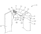
图3为高脚椅的立体示意图; Fig. 3 is the three-dimensional schematic diagram of high chair;
图4为本发明第一实施例的收合机构的示意图; Fig. 4 is the schematic diagram of the folding mechanism of the first embodiment of the present invention;
图5为收合机构各元件的分解示意图; Figure 5 is an exploded schematic view of the components of the folding mechanism;
图6为收合机构释锁的状态示意图; Figure 6 is a schematic diagram of the release state of the retracting mechanism;
图7为后脚组相对前脚组枢转至收合位置的示意图; Figure 7 is a schematic diagram of the rear foot group pivoting to the retracted position relative to the front foot group;
图8为后脚组的枢接端的示意图; Fig. 8 is the schematic diagram of the articulated end of rear foot group;
图9为本发明第二实施例的收合机构的示意图; Fig. 9 is the schematic diagram of the folding mechanism of the second embodiment of the present invention;
图10为收合机构各元件的分解示意图; Figure 10 is an exploded schematic view of the elements of the folding mechanism;
图11为收合机构释锁的状态示意图; Figure 11 is a schematic diagram of the release state of the retracting mechanism;
图12为后脚组相对前脚组枢转至收合位置的示意图; Figure 12 is a schematic diagram of the rear foot group pivoting to the retracted position relative to the front foot group;
图13为本发明第三实施例的收合机构的示意图; Fig. 13 is the schematic diagram of the folding mechanism of the third embodiment of the present invention;
图14为收合机构各元件的分解示意图; Figure 14 is an exploded schematic view of the elements of the folding mechanism;
图15为收合机构释锁的状态示意图; Figure 15 is a schematic diagram of the release state of the retracting mechanism;
图16为后脚组相对前脚组枢转至收合位置的示意图。 Fig. 16 is a schematic diagram of the pivoting of the rear foot group relative to the front foot group to the retracted position. the
主要元件符号说明 Description of main component symbols
10 座椅 20 前脚组 10
30 后脚组 31 枢接端 30
60、70、80 收合机构 61、71、81 座体 60, 70, 80
62、72、82 卡合件 63、73、83 致动件 62, 72, 82
64、74、84 转轴体 65、75、85 弹性件 64, 74, 84
100 高脚椅 311 第一抵靠部 100
312 第二抵靠部 611、711、760 滑槽 312
612、731 轴部 613 限位件 612, 731 Shaft
621、821 第二斜面 631、642 长槽 621, 821
632、832 第一斜面 641、741、811 卡槽 632, 832
721 斜向槽 731 第二轴部 721
N1、N2 方向 F1、F2 方向 N1, N2 Direction F1, F2 Direction
40 架体 200 上部件 40
202 下部件 614 第一臂部 202
615、810 第二臂部 616 开孔 615, 810 Second arm 616 Opening
620、720、820 卡合端 630、732 按压部 620, 720, 820 snapping
633 致动部 76 外盖 633
具体实施方式Detailed ways
请参考图1以及图2,其为本发明所揭露的高脚椅100的示意图,其中图1为高脚椅100于展开状态的示意图,图2为高脚椅100于收合状态的示意图。高脚椅100包含由一前脚组20以及一后脚组30所组成的架体40、设置于前后脚组20、30枢接处的一收合机构60(请参考图4)以及承载于架体40上的一座椅10。 Please refer to FIG. 1 and FIG. 2 , which are schematic diagrams of the
请参考图3,图3为高脚椅100的立体示意图。后脚组30大致与前脚组20中间位置枢接。前脚组20包含一上部件200及一下部件202,座椅10安装于上部件200,上部件200可相对下部件202移动,以进行座椅10的高度调整,后脚组20则是与下部件202上端枢接。 Please refer to FIG. 3 , which is a three-dimensional schematic view of the
在高脚椅100展开时,幼儿可以坐于座椅10内,并且座椅10的高度可自由调整以方便照顾者照顾坐在座椅10内的幼儿,座椅10可固定于架体40上,或是自架体40上拆卸下来以方便收纳或是放置于一般餐椅上以供较大的幼童使用。架体40的前脚组20的下部件202以及后脚组30在此实施例中则呈U型管件(如图3即显示本实施例的前脚组20的下部件202与后脚组30的U型结构)。 When the
架体40的前脚组20以及后脚组30彼此枢接,收合机构60则设置于后脚组30枢接于前脚组20的枢接处。架体40可通过收合机构60在一如图1的展开位置及一如图2的收合位置间移动。在展开位置时,后脚组30的下端与前脚组20的下端相互远离并相互固定,在收合位置时,前脚组20可与后脚组30相互枢转靠近,当前脚组20与后脚组30枢转至该收合位置时,高脚椅100可以收合至较小的体积以方便收纳。 The front foot set 20 and the rear foot set 30 of the
请参考图4以及图5,图4为本发明第一实施例的收合机构60的示意图,图5为收合机构60各元件的分解示意图,其中图4的收合机构60处于锁固状态后,此时后脚组30无法相对前脚组20枢转而使架体40被限制于该展开位置。收合机构60包含有一座体61、一卡合件62、一致动件63、一转轴体64以及一弹性件65。 Please refer to FIG. 4 and FIG. 5. FIG. 4 is a schematic diagram of the
如图4及图5所示,座体61包含一第一臂部614及一与第一臂部614成一角度连接的第二臂部615,在此实施例中,第一臂部614较第二臂部615短。第一臂部614设置于前脚组20的下部件202顶端,转轴体64连接于后脚组30的一枢接端31,同时另外与座体61的第二臂部615枢接,因此转轴 体64以及后脚组30可以相对座体61(以及座体61所在的前脚组20)枢转。在座体61的第二臂部615内具有一滑槽611,在本实施例中,滑槽611呈F1-F2方向走向,卡合件62则滑动地设置于滑槽611内,且可在滑槽611内沿F1或F2方向移动,以在如图4所示的一锁固位置或如图6所示的一释锁位置间移动,卡合件62包含一卡合端620及一位于卡合端620上方的一第二斜面621。弹性件65可为一弹簧,在本实施例中,弹性件65也设置于滑槽611内,且连接于卡合件62以及座体61间,当卡合件62在滑槽611内移动时,弹性件65会受压缩而具有弹性偏压力。致动件63可为一按钮,在本实施例中,致动件63包含一按压部630及一从按压部630横向延伸略呈三角形的致动部633,按压部630可从座体61的一开口突出,以供使用者操作,致动部633具有一可与卡合件62的第二斜面621相对应的第一斜面632及一长槽631,且座体61具有一轴部612延伸于长槽631,使得致动件63以可沿N1或N2方向相对座体61移动的方式设置于座体61上。在此实施例中,F1-F2及N1-N2方向相互垂直。 As shown in Figures 4 and 5, the
在本实施例中,转轴体64具有一卡槽641。如图4所示,当收合机构60的卡合件62位于锁固位置时,卡合件62的卡合端620延伸出座体61的滑槽611,且伸入于转轴体64的卡槽641内,此时卡合件62抵住卡槽641两侧壁面,且致动部633的第一斜面632与卡合件62的第二斜面621相抵接,转轴体64及连接的后脚组30无法相对座体61及前脚组20转动,以达到将架体40维持在该展开位置的目的。 In this embodiment, the
请参考图6以及图7,图6为收合机构60释锁状态示意图,图7为后脚组30相对前脚组20枢转至该收合位置的示意图。当欲通过收合机构60释锁以收合架体40至较小的收纳体积时,可以按压致动件63的按压部630,使致动件63沿N1方向向座体61移动。此时,致动件63的第一斜面632会与卡合件62的第二斜面621产生干涉作用,并推动卡合件62于滑槽611内向F2方向滑动,使卡合件62的卡合端620退出转轴体64的卡槽641,且使卡合件62整个退回座体61的滑槽611内。此时,卡合件62位于图6的该释锁位置,转轴体64的卡槽641两侧壁面不再被卡合件62抵位,转轴体64以及后脚组30即可相对座体61(以及前脚组20)枢转至如图7所示的收合位置,完成架体40的收合。 Please refer to FIG. 6 and FIG. 7 , FIG. 6 is a schematic diagram of the
当卡合件62位于如图6的该释锁位置时,连接于卡合件62与座体61 之间的弹性件65被压缩,从而在后脚组30自图7的该收合位置相对前脚组20枢转至图6的该展开位置时,弹性件65所具有的弹性偏压力会再度推动卡合件62的卡合端620自座体61的滑槽611向F1方向延伸于转轴体64的卡槽641内,以再度将架体40维持在该展开位置。 When the engaging
此外,如图4、图5以及图7所示,转轴体64在侧壁上具有一长槽642,一限位件613穿设于座体61的第二臂部615的开孔616及转轴体64的长槽642,并在前脚组20相对后脚组30枢转时可在长槽642内移动。在本实施例中,限位件613可以是设置在座体61上的铆钉,但不以此为限。请一并参考图8,图8为后脚组30的枢接端31的示意图。后脚组30的枢接端31具有一第一抵靠部311以及一第二抵靠部312。当架体40位于图4的展开位置时,第一抵靠部311刚好抵靠在限位件613上,以避免座椅10过载时导致前脚组20及后脚组30过度张开的问题产生。当架体位于图6的收合位置时,第二抵靠部312则会抵靠在限位件613上,以防止后脚组30过度旋转,且此时座体61刚好可遮盖住转轴体64的卡槽641,进而防止出现手指夹陷的空隙。 In addition, as shown in FIGS. 4 , 5 and 7 , the
请参考图9以及图10,图9为本发明第二实施例的收合机构70的示意图,图10为收合机构70各元件的分解示意图,其中图9的收合机构70处于锁固状态,此时后脚组30无法相对前脚组20枢转而使架体40被限制于该展开位置。收合机构70包含有一座体71、一卡合件72、一致动件73、一转轴体74以及一弹性件75。 Please refer to FIG. 9 and FIG. 10. FIG. 9 is a schematic diagram of a
第二实施例的收合机构70与前述第一实施例的收合机构60的主要不同之处在于卡合件72及致动件73,卡合件72具有一卡合端720及一位于卡合端720相对一端的斜向槽721,致动件73在此实施例中略呈三角形,具有一设置于顶端的轴部731及一按压部732。轴部731延伸于斜向槽721内,且二端分别卡入座体71内壁的滑槽及外盖76上的滑槽760中,以移动地设置于座体71上。轴部731可在斜向槽721内移动。当致动件73沿N1或N2方向移动时,轴部731会在斜向槽721内移动以带动卡合件72于滑槽711内沿F1或F2方向移动,在此实施例中,F1-F2及N1-N2方向不互相平行而呈一角度。 The main difference between the
请参考图11以及图12,图11为收合机构70释锁状态示意图,图12为后脚组30相对前脚组20枢转至收合位置的示意图。当欲通过收合机构70 释锁以收合架体至较小的收纳体积时,可以按压致动件73,使致动件73沿N1方向向座体71移动。此时,致动件73的轴部731会在斜向槽721内移动以带动卡合件72于滑槽711内沿F2方向移动,使卡合件72的卡合端720退出转轴体74的卡槽741,且使卡合件72整个退回座体71的滑槽711内。此时,卡合件72位于图11的该释锁位置,而转轴体74以及后脚组30即可相对座体71(以及前脚组20)枢转至如图12所示的收合位置,完成架体40的收合。此外,第二实施例的收合机构70的其他工作原理与前述第一实施例的收合机构60大致相同,且后脚组30的枢接端31同样具有一第一抵靠部311以及一第二抵靠部312,以在架体40位于展开位置或收合位置时,分别抵靠在限位件613上,在此不再赘述。 Please refer to FIG. 11 and FIG. 12 , FIG. 11 is a schematic diagram of the unlocked state of the
请参考图13以及图14,图13为本发明第三实施例的收合机构80的示意图,图14为收合机构80各元件的分解示意图,其中图13的收合机构80处于锁固状态,此时后脚组30无法相对前脚组20枢转而使架体40被限制于该展开位置。收合机构80包含有一座体81、一卡合件82、一致动件83、一转轴体84以及一弹性件85。 Please refer to FIG. 13 and FIG. 14. FIG. 13 is a schematic diagram of a
如图13所示,座体81设置于前脚组20的一端,转轴体84连接于后脚组30的一枢接端31,同时另外枢接于座体81的第二臂部810,因此转轴体84以及后脚组30可以相对座体81(以及座体81所在的前脚组20)枢转。卡合件82可滑动地与转轴体84连接,且可移动延伸出转轴体84以及后脚组30的枢接端31。在座体81内具有一卡槽811,在本实施例中,卡合件82一端具有卡合端820卡合于卡槽811,且可沿F1或F2方向移动至如图13所示的一锁固位置或如图15所示的一释锁位置,该卡合端820具有一第二斜面821。弹性件85可为一弹簧,在本实施例中,弹性件85设置于后脚组30的枢接端31与卡合件82之间,当卡合件82沿F1方向移动时,弹性件85会受压缩而具有弹性偏压力。致动件83可为一按钮,在本实施例中,致动件83枢接于座体81的第二臂部810,其在相对该枢接点的一端具有一第一斜面832致动面以与卡合件82的第二斜面821相对应,致动件83以可沿N1或N2方向相对座体81枢转的方式设置于座体81上。 As shown in Figure 13, the
如图13所示,当收合机构80的卡合件82位于该锁固位置时,卡合件82的卡合端820延伸于座体81的卡槽811内,此时卡合件82抵住卡槽811侧壁,致动件83的第一斜面832致动面则与卡合件82的卡合端820的第二 斜面821斜面相抵,此时转轴体84及连接的后脚组30无法相对座体81及前脚组20转动,以达到将架体40维持在该展开位置的作用。 As shown in FIG. 13 , when the engaging
请参考图15以及图16,图15为收合机构80释锁的状态示意图,图16为后脚组30相对前脚组20枢转至该收合位置的示意图。当欲通过收合机构80释锁以收合架体至较小的收纳体积时,可以按压致动件83,使致动件83沿N1方向相对座体81转动。此时,致动件83的第一斜面832会与卡合件82的第二斜面821产生干涉作用,并推动卡合件82向F1方向滑动,使卡合件82退出座体81的卡槽811。此时,卡合件82位于图15的该释锁位置,而转轴体84以及后脚组30即可相对座体81(以及前脚组20)枢转至如图16所示的收合位置,完成收合的动作。 Please refer to FIG. 15 and FIG. 16 , FIG. 15 is a schematic diagram of the unlocked state of the
当后脚组30自图16的该收合位置相对前脚组20枢转至图15的该展开位置时,连接于卡合件82与后脚组30之间的弹性件85会被压缩,而弹性件85所具有的弹性偏压力会再度推动卡合件82延伸于座体81的卡槽811内,以再度将架体维持在该展开位置。 When the
本发明所揭露的高脚椅在后脚组与前脚组枢转处设置收合机构,由使用者按压致动件即可轻易地完成单一致动的收合动作。当致动件被按压时,致动件带动卡合件相对座体移动至释锁位置,使后脚组与前脚组脱离卡合的状态,从而后脚组可相对前脚组枢转,以收合高脚椅。本发明的收合机构不仅结构简单,且方便使用者收合高脚椅。 The high chair disclosed by the present invention is provided with a folding mechanism at the pivot point of the rear foot group and the front foot group, and the user can easily complete the single-actuated folding action by pressing the actuator. When the actuating part is pressed, the actuating part drives the engaging part to move relative to the seat body to the unlocking position, so that the rear foot group and the front foot group are out of the engaged state, so that the rear foot group can pivot relative to the front foot group to fold the high foot chair. The folding mechanism of the present invention is not only simple in structure, but also convenient for the user to fold the high chair. the
以上所述仅为本发明的较佳实施例,凡依本发明申请专利范围所做的均等变化与修饰,皆应属本发明的涵盖范围。 The above descriptions are only preferred embodiments of the present invention, and all equivalent changes and modifications made according to the scope of the patent application of the present invention shall fall within the scope of the present invention. the
Claims (20)
Priority Applications (4)
| Application Number | Priority Date | Filing Date | Title |
|---|---|---|---|
| CN2009100067922A CN101548835B (en) | 2008-04-03 | 2009-02-27 | high chair |
| US12/416,937 US8419121B2 (en) | 2008-04-03 | 2009-04-02 | High chair |
| JP2009157487A JP5284200B2 (en) | 2009-02-27 | 2009-07-02 | High chair |
| US13/845,124 US8967710B2 (en) | 2008-04-03 | 2013-03-18 | High chair |
Applications Claiming Priority (3)
| Application Number | Priority Date | Filing Date | Title |
|---|---|---|---|
| US4192208P | 2008-04-03 | 2008-04-03 | |
| US61/041,922 | 2008-04-03 | ||
| CN2009100067922A CN101548835B (en) | 2008-04-03 | 2009-02-27 | high chair |
Publications (2)
| Publication Number | Publication Date |
|---|---|
| CN101548835A CN101548835A (en) | 2009-10-07 |
| CN101548835B true CN101548835B (en) | 2011-06-29 |
Family
ID=41132591
Family Applications (1)
| Application Number | Title | Priority Date | Filing Date |
|---|---|---|---|
| CN2009100067922A Active CN101548835B (en) | 2008-04-03 | 2009-02-27 | high chair |
Country Status (3)
| Country | Link |
|---|---|
| US (2) | US8419121B2 (en) |
| JP (1) | JP5284200B2 (en) |
| CN (1) | CN101548835B (en) |
Families Citing this family (28)
| Publication number | Priority date | Publication date | Assignee | Title |
|---|---|---|---|---|
| GB2460942B (en) * | 2008-06-19 | 2012-10-24 | Wonderland Nursery Goods | Child chair having engaging assembly for a seat |
| CN101907125B (en) * | 2010-08-03 | 2012-07-18 | 陈荣财 | High chair joint |
| CN202169958U (en) * | 2011-06-30 | 2012-03-21 | 明门香港股份有限公司 | Cart with auxiliary wheels |
| CN202820499U (en) * | 2012-02-21 | 2013-03-27 | 中山市隆成日用制品有限公司 | Baby carrier support frame |
| CN103863380B (en) * | 2012-12-13 | 2016-04-06 | 明门香港股份有限公司 | Infant carrier and safety lock mechanism thereof |
| USD742657S1 (en) | 2013-09-18 | 2015-11-10 | Graco Children's Products, Inc. | High chair |
| CN105029956B (en) | 2014-05-02 | 2018-04-03 | 明门香港股份有限公司 | Children high chair and operation method thereof |
| US11723477B2 (en) | 2015-04-25 | 2023-08-15 | Kids2, Inc. | Convertible highchair |
| US10588424B2 (en) | 2015-04-25 | 2020-03-17 | Kids2, Inc. | Convertible high chair |
| US11877671B2 (en) | 2015-04-25 | 2024-01-23 | Kids2, Inc. | Convertible high chair |
| US9752364B2 (en) * | 2015-06-08 | 2017-09-05 | Dowco, Inc. | Hinge |
| NL2016449B1 (en) * | 2016-03-17 | 2017-10-05 | Mutsy Bv | Device for transporting a child. |
| DE202016105140U1 (en) * | 2016-09-15 | 2016-12-19 | Cybex Gmbh | Stroller frame and stroller |
| US20180146796A1 (en) * | 2016-11-29 | 2018-05-31 | Artsana Usa, Inc. | Collapsible crib frame |
| US10321769B2 (en) * | 2016-11-29 | 2019-06-18 | Artsana Usa, Inc. | Clip-on child booster seat |
| TWI656856B (en) * | 2017-10-20 | 2019-04-21 | Unique Product & Design Co., Ltd. | Carrying device |
| CN110025165A (en) * | 2019-01-07 | 2019-07-19 | 明门瑞士股份有限公司 | Foldable high chair |
| CN109700233B (en) * | 2019-01-25 | 2024-10-29 | 宁波精英车业有限公司 | A height adjustment structure for children's dining chair and children's dining chair |
| US10858072B1 (en) | 2019-06-27 | 2020-12-08 | Dowco, Inc. | Articulated top assist mechanism |
| CN112515407B (en) | 2019-09-18 | 2024-11-15 | 明门瑞士股份有限公司 | Folding positioning mechanism and baby seat |
| US11046394B1 (en) | 2020-05-04 | 2021-06-29 | Dowco, Inc. | Reinforced articulated top |
| US11472512B1 (en) | 2021-05-17 | 2022-10-18 | Dowco, Inc. | Reinforced articulated top |
| US11807341B2 (en) | 2020-05-04 | 2023-11-07 | Dowco, Inc. | Reinforced articulated top |
| USD978545S1 (en) | 2020-09-17 | 2023-02-21 | Kids2, Inc. | Modular highchair |
| CN114802403A (en) * | 2021-01-22 | 2022-07-29 | 明门(中国)幼童用品有限公司 | Baby carriage |
| CN116172366A (en) * | 2021-11-29 | 2023-05-30 | 宝钜(中国)儿童用品有限公司 | high chair |
| CN116264929B (en) * | 2021-12-17 | 2025-11-04 | 明门(中国)幼童用品有限公司 | Portable and foldable bar stool |
| CN220069303U (en) * | 2023-04-07 | 2023-11-24 | 厦门梦贝比儿童用品有限公司 | A multi-purpose children's dining chair |
Citations (4)
| Publication number | Priority date | Publication date | Assignee | Title |
|---|---|---|---|---|
| CN2634944Y (en) * | 2003-06-25 | 2004-08-25 | 明门实业股份有限公司 | Collapsible baby high chair |
| EP1692973A1 (en) * | 2005-02-18 | 2006-08-23 | Atico International USA, Inc. | Anti-pinching device for use in a folding chair |
| CN1907182A (en) * | 2005-08-02 | 2007-02-07 | 天使圣临公司 | Folding high chair |
| CN1985716A (en) * | 2005-12-20 | 2007-06-27 | Evenflo有限责任公司 | Juvenile high chair |
Family Cites Families (53)
| Publication number | Priority date | Publication date | Assignee | Title |
|---|---|---|---|---|
| USRE23744E (en) * | 1953-11-24 | Push and pull friction type | ||
| US316810A (en) * | 1885-04-28 | Abnee niebel | ||
| US2591373A (en) * | 1950-12-16 | 1952-04-01 | Petruch Methodius Ciryllus | Lockable knee joint for orthopedic braces or artificial limbs |
| US2812961A (en) * | 1955-06-21 | 1957-11-12 | A J Hosmer Corp | Prosthetic locking hinge |
| SE377757B (en) * | 1971-06-23 | 1975-07-28 | Castelli Sas Anonima | |
| IT1017185B (en) * | 1974-07-16 | 1977-07-20 | Artsana Spa | FOLDABLE BABY BACKPACK |
| DE2514940C2 (en) * | 1975-04-05 | 1985-03-07 | Wilhelm Bahmüller Maschinen- und Apparatebau, 7067 Plüderhausen | Joint that can be locked in several working positions to connect the ladder stiles to a ladder that can be locked in several positions or the like. |
| DE2618292C3 (en) | 1976-04-27 | 1978-10-05 | Fa. Heinrich Wilhelm Dreyer, 4515 Bad Essen | Standing work seat |
| US4191397A (en) * | 1977-06-15 | 1980-03-04 | Kassai Kabushikikaisha | Baby carriage |
| US4441757A (en) * | 1980-02-13 | 1984-04-10 | Jesus Gasca Burges | Structural joint for folding chair |
| DE8131385U1 (en) * | 1981-10-28 | 1982-03-25 | Benjamin Products B.V., 4879 Etten-Leur | "FOLDABLE BABY SEAT" |
| JPS59113499U (en) * | 1983-01-20 | 1984-07-31 | 青輪企業股ふん有限公司 | Joint device for folding ladders, furniture, etc. |
| US4540306A (en) * | 1983-10-19 | 1985-09-10 | Wang Chien Yuan | Positioning joint for folding ladders |
| US4543006A (en) * | 1984-11-16 | 1985-09-24 | Wang Chien Yuan | Foldable multi-position ladder joint |
| US4645371A (en) * | 1986-05-01 | 1987-02-24 | Wang Chien Yuan | Safety joint mechanism, particularly for folding ladders |
| KR910000302Y1 (en) * | 1987-02-21 | 1991-01-18 | 장문수 | Hinge for foldabel ladder |
| US4805737A (en) * | 1987-11-18 | 1989-02-21 | Peng Ching L | Ladder positioning mechanism |
| US4904018A (en) * | 1988-10-20 | 1990-02-27 | Young Noah W | All-terrain foldable seat |
| US4925329A (en) * | 1988-11-25 | 1990-05-15 | Chuang Yuan Chan | Joint for foldable ladders |
| US4983063A (en) * | 1990-04-12 | 1991-01-08 | Phillips Terry J | Bicycle seat adapter |
| GB2252494B (en) * | 1991-02-09 | 1994-09-07 | David Robert Reade | Improvements relating to collapsible seats |
| US5169257A (en) * | 1992-06-26 | 1992-12-08 | Liou Shuen Yi | Angle adjustable joint |
| US5244301A (en) * | 1992-09-22 | 1993-09-14 | Kurke Martin I | Bicycle seat mount |
| JP3418486B2 (en) * | 1994-09-06 | 2003-06-23 | 成興工業株式会社 | Height-adjustable folding chair |
| US6547321B2 (en) * | 2001-07-17 | 2003-04-15 | Chung-Sen Wu | Folding chair |
| US6877801B2 (en) * | 2001-10-04 | 2005-04-12 | Mattel, Inc. | Adjustable child support structure with accessories |
| US6645080B1 (en) * | 2002-11-26 | 2003-11-11 | Graco Children's Products Inc. | Foldable swing with seat recline mechanism |
| TW573658U (en) * | 2003-04-08 | 2004-01-21 | J & X Pros & Orth Co Ltd | Foldable walking assisted scooter |
| GB2403768B (en) * | 2003-06-30 | 2005-07-13 | Cheng Kenny | Folding device for highchair |
| GB2403898B (en) * | 2003-07-18 | 2005-11-16 | Wonderland Nursery Goods | Collapsible high chair for children |
| US7021650B2 (en) * | 2003-08-07 | 2006-04-04 | Wonderland Nurserygoods Co., Ltd. | Collapsing device for carrier |
| DE202004006903U1 (en) * | 2004-04-29 | 2004-07-01 | Heinz Kettler Gmbh & Co Kg | Foldable frame for a tricycle, balance bike or children's bike |
| EP1744941B1 (en) * | 2004-04-30 | 2014-11-19 | BabyJogger, LLC | Folding baby stroller |
| JP2008541956A (en) | 2005-06-09 | 2008-11-27 | ファンタスティック リミテッド | Adjustable pediatric chair |
| CN2875875Y (en) * | 2005-09-30 | 2007-03-07 | 明门实业股份有限公司 | Child car safety seat armrest rotation adjustment device |
| US7156405B1 (en) * | 2005-10-13 | 2007-01-02 | James Wong Ka Ming | Folding scooter |
| US7419171B1 (en) * | 2005-10-13 | 2008-09-02 | James Wong Ka Ming | Folding scooter with foot board connector |
| CN2927864Y (en) * | 2006-02-21 | 2007-08-01 | 明门实业股份有限公司 | foldable seat |
| ITVR20060060A1 (en) * | 2006-03-30 | 2007-09-30 | Inglesina Baby Spa | STRUCTURE OF CHAIRS |
| DE602006018863D1 (en) * | 2006-04-21 | 2011-01-27 | Wonderland Nursery Goods | Foldable stroller |
| CN200980503Y (en) * | 2006-06-20 | 2007-11-28 | 明门实业股份有限公司 | High chair folding device |
| CN201082719Y (en) * | 2006-09-21 | 2008-07-09 | 明门实业股份有限公司 | Foldable baby carriage |
| GB2442127B (en) * | 2006-09-21 | 2011-08-31 | Wonderland Nursery Goods | Foldable stroller |
| CN201116134Y (en) * | 2006-10-22 | 2008-09-17 | 明门实业股份有限公司 | Baby carriage with single folding shaft and single-axis frame folding mechanism |
| DE202006017551U1 (en) * | 2006-11-17 | 2007-03-01 | Ilinko Ltd. | Frame and children accommodating device e.g. seat, connecting device for e.g. perambulator, has locking unit and snap-fit that are movable in same direction from locking position into unlocking position by actuation of pushbuttons |
| CN201016003Y (en) * | 2007-01-18 | 2008-02-06 | 明门实业股份有限公司 | Baby carriage safety lock and baby carriage frame with same |
| US8011722B2 (en) * | 2007-03-15 | 2011-09-06 | Wonderland Nurserygoods Company Limited | Foldable frame with detachable infant carrier |
| CN201082718Y (en) * | 2007-07-19 | 2008-07-09 | 明门实业股份有限公司 | Single-hand folding actuating mechanism of baby carriage |
| US7900952B2 (en) * | 2008-02-08 | 2011-03-08 | Dick Cone Industrial Design, Inc. | Folding stroller including locking mechanism |
| US7878584B2 (en) * | 2008-06-19 | 2011-02-01 | Wonderland Nurserygoods Company Limited | Safety belt storage assembly and child seat having the same |
| GB2460942B (en) * | 2008-06-19 | 2012-10-24 | Wonderland Nursery Goods | Child chair having engaging assembly for a seat |
| CN101785618B (en) * | 2009-01-22 | 2014-04-09 | 明门香港股份有限公司 | toddler seat |
| CN101862090B (en) * | 2009-04-15 | 2011-12-07 | 明门实业股份有限公司 | High chair retractable mechanism |
-
2009
- 2009-02-27 CN CN2009100067922A patent/CN101548835B/en active Active
- 2009-04-02 US US12/416,937 patent/US8419121B2/en active Active
- 2009-07-02 JP JP2009157487A patent/JP5284200B2/en active Active
-
2013
- 2013-03-18 US US13/845,124 patent/US8967710B2/en active Active
Patent Citations (4)
| Publication number | Priority date | Publication date | Assignee | Title |
|---|---|---|---|---|
| CN2634944Y (en) * | 2003-06-25 | 2004-08-25 | 明门实业股份有限公司 | Collapsible baby high chair |
| EP1692973A1 (en) * | 2005-02-18 | 2006-08-23 | Atico International USA, Inc. | Anti-pinching device for use in a folding chair |
| CN1907182A (en) * | 2005-08-02 | 2007-02-07 | 天使圣临公司 | Folding high chair |
| CN1985716A (en) * | 2005-12-20 | 2007-06-27 | Evenflo有限责任公司 | Juvenile high chair |
Also Published As
| Publication number | Publication date |
|---|---|
| US8419121B2 (en) | 2013-04-16 |
| US20130214564A1 (en) | 2013-08-22 |
| JP5284200B2 (en) | 2013-09-11 |
| US8967710B2 (en) | 2015-03-03 |
| US20090250977A1 (en) | 2009-10-08 |
| JP2010201151A (en) | 2010-09-16 |
| CN101548835A (en) | 2009-10-07 |
Similar Documents
| Publication | Publication Date | Title |
|---|---|---|
| CN101548835B (en) | high chair | |
| CN101785618B (en) | toddler seat | |
| CN101862090B (en) | High chair retractable mechanism | |
| CN113104091B (en) | Frame folding mechanism, frame locking mechanism, backrest unlocking mechanism and baby carriage | |
| TWI839209B (en) | Foldable locking mechanism | |
| CN107364483B (en) | baby stroller | |
| TWI817901B (en) | Carrier frame | |
| TWI795166B (en) | Crib frame | |
| CN112224267B (en) | Rod folding locking mechanism and stroller frame | |
| CN209833735U (en) | Baby carriage frame folding device capable of being interlocked and unlocked by seat folding | |
| TWI906132B (en) | Bed frame structure | |
| CN100367894C (en) | folding seat | |
| TW202241747A (en) | Vehicle frame and stroller | |
| CN108313110B (en) | Folding mechanism and infant carrier | |
| CN201365729Y (en) | Operating device for child seat and child seat having the same | |
| CN101513311A (en) | Portable diaper changing table | |
| CN211139435U (en) | An easy-to-fold stroller frame | |
| CN109808759A (en) | Perambulator and its fold hook device | |
| CN111038571B (en) | A foldable baby stroller | |
| CN209018217U (en) | a booster chair | |
| CN213292404U (en) | Locking structure of children's shallow and children's shallow | |
| CN102211604B (en) | Collapsible infant carrier | |
| CN121894027A (en) | Child cart | |
| CN115817618A (en) | Seats and passenger equipment | |
| CN101907125A (en) | High chair joint |
Legal Events
| Date | Code | Title | Description |
|---|---|---|---|
| C06 | Publication | ||
| PB01 | Publication | ||
| C10 | Entry into substantive examination | ||
| SE01 | Entry into force of request for substantive examination | ||
| C14 | Grant of patent or utility model | ||
| GR01 | Patent grant |