CN101518466A - Biopsy site marker deployment instrument - Google Patents
Biopsy site marker deployment instrument Download PDFInfo
- Publication number
- CN101518466A CN101518466A CN200910118214A CN200910118214A CN101518466A CN 101518466 A CN101518466 A CN 101518466A CN 200910118214 A CN200910118214 A CN 200910118214A CN 200910118214 A CN200910118214 A CN 200910118214A CN 101518466 A CN101518466 A CN 101518466A
- Authority
- CN
- China
- Prior art keywords
- label
- sleeve pipe
- far
- label body
- opening
- Prior art date
- Legal status (The legal status is an assumption and is not a legal conclusion. Google has not performed a legal analysis and makes no representation as to the accuracy of the status listed.)
- Pending
Links
- 238000001574 biopsy Methods 0.000 title claims description 59
- 239000003550 marker Substances 0.000 title abstract description 17
- 230000001737 promoting effect Effects 0.000 claims description 4
- 230000006835 compression Effects 0.000 abstract description 2
- 238000007906 compression Methods 0.000 abstract description 2
- 239000000463 material Substances 0.000 description 21
- 238000005516 engineering process Methods 0.000 description 14
- 230000004048 modification Effects 0.000 description 14
- 238000012986 modification Methods 0.000 description 14
- 239000000758 substrate Substances 0.000 description 14
- 102000008186 Collagen Human genes 0.000 description 13
- 108010035532 Collagen Proteins 0.000 description 13
- 229920001436 collagen Polymers 0.000 description 13
- 238000000034 method Methods 0.000 description 13
- 210000001519 tissue Anatomy 0.000 description 11
- 230000006872 improvement Effects 0.000 description 6
- 238000002372 labelling Methods 0.000 description 6
- 238000003780 insertion Methods 0.000 description 5
- 230000037431 insertion Effects 0.000 description 5
- 239000004033 plastic Substances 0.000 description 4
- 229920003023 plastic Polymers 0.000 description 4
- 230000005855 radiation Effects 0.000 description 4
- 238000005452 bending Methods 0.000 description 3
- 238000004140 cleaning Methods 0.000 description 3
- 238000003384 imaging method Methods 0.000 description 3
- 230000008569 process Effects 0.000 description 3
- 238000001356 surgical procedure Methods 0.000 description 3
- 241000283690 Bos taurus Species 0.000 description 2
- IAYPIBMASNFSPL-UHFFFAOYSA-N Ethylene oxide Chemical compound C1CO1 IAYPIBMASNFSPL-UHFFFAOYSA-N 0.000 description 2
- 229920002614 Polyether block amide Polymers 0.000 description 2
- 229920000954 Polyglycolide Polymers 0.000 description 2
- RTAQQCXQSZGOHL-UHFFFAOYSA-N Titanium Chemical compound [Ti] RTAQQCXQSZGOHL-UHFFFAOYSA-N 0.000 description 2
- 230000008859 change Effects 0.000 description 2
- 238000011503 in vivo imaging Methods 0.000 description 2
- 238000010348 incorporation Methods 0.000 description 2
- 229910052751 metal Inorganic materials 0.000 description 2
- 239000002184 metal Substances 0.000 description 2
- 229920000747 poly(lactic acid) Polymers 0.000 description 2
- 239000004626 polylactic acid Substances 0.000 description 2
- 238000004080 punching Methods 0.000 description 2
- 238000007789 sealing Methods 0.000 description 2
- 230000001954 sterilising effect Effects 0.000 description 2
- 238000004659 sterilization and disinfection Methods 0.000 description 2
- 238000005481 NMR spectroscopy Methods 0.000 description 1
- 235000010627 Phaseolus vulgaris Nutrition 0.000 description 1
- 244000046052 Phaseolus vulgaris Species 0.000 description 1
- 239000004952 Polyamide Substances 0.000 description 1
- 239000004775 Tyvek Substances 0.000 description 1
- 229920000690 Tyvek Polymers 0.000 description 1
- 230000003213 activating effect Effects 0.000 description 1
- 230000000844 anti-bacterial effect Effects 0.000 description 1
- 239000011324 bead Substances 0.000 description 1
- 230000008901 benefit Effects 0.000 description 1
- 230000015572 biosynthetic process Effects 0.000 description 1
- 235000019994 cava Nutrition 0.000 description 1
- 229920002678 cellulose Polymers 0.000 description 1
- 239000001913 cellulose Substances 0.000 description 1
- 230000001143 conditioned effect Effects 0.000 description 1
- 230000008878 coupling Effects 0.000 description 1
- 238000010168 coupling process Methods 0.000 description 1
- 238000005859 coupling reaction Methods 0.000 description 1
- 238000005520 cutting process Methods 0.000 description 1
- 229920001971 elastomer Polymers 0.000 description 1
- 239000000806 elastomer Substances 0.000 description 1
- 210000003811 finger Anatomy 0.000 description 1
- 239000012634 fragment Substances 0.000 description 1
- 229920006258 high performance thermoplastic Polymers 0.000 description 1
- 239000000017 hydrogel Substances 0.000 description 1
- 239000000203 mixture Substances 0.000 description 1
- 238000005457 optimization Methods 0.000 description 1
- 229920002647 polyamide Polymers 0.000 description 1
- 239000004633 polyglycolic acid Substances 0.000 description 1
- 229920000642 polymer Polymers 0.000 description 1
- 238000005381 potential energy Methods 0.000 description 1
- 230000008439 repair process Effects 0.000 description 1
- 210000004872 soft tissue Anatomy 0.000 description 1
- 238000003860 storage Methods 0.000 description 1
- 238000007920 subcutaneous administration Methods 0.000 description 1
- 210000003813 thumb Anatomy 0.000 description 1
- 239000010936 titanium Substances 0.000 description 1
- 229910052719 titanium Inorganic materials 0.000 description 1
- 238000013519 translation Methods 0.000 description 1
Images






Classifications
-
- A—HUMAN NECESSITIES
- A61—MEDICAL OR VETERINARY SCIENCE; HYGIENE
- A61B—DIAGNOSIS; SURGERY; IDENTIFICATION
- A61B90/00—Instruments, implements or accessories specially adapted for surgery or diagnosis and not covered by any of the groups A61B1/00 - A61B50/00, e.g. for luxation treatment or for protecting wound edges
- A61B90/39—Markers, e.g. radio-opaque or breast lesions markers
-
- A—HUMAN NECESSITIES
- A61—MEDICAL OR VETERINARY SCIENCE; HYGIENE
- A61B—DIAGNOSIS; SURGERY; IDENTIFICATION
- A61B10/00—Instruments for taking body samples for diagnostic purposes; Other methods or instruments for diagnosis, e.g. for vaccination diagnosis, sex determination or ovulation-period determination; Throat striking implements
- A61B10/02—Instruments for taking cell samples or for biopsy
- A61B10/0233—Pointed or sharp biopsy instruments
-
- A—HUMAN NECESSITIES
- A61—MEDICAL OR VETERINARY SCIENCE; HYGIENE
- A61B—DIAGNOSIS; SURGERY; IDENTIFICATION
- A61B90/00—Instruments, implements or accessories specially adapted for surgery or diagnosis and not covered by any of the groups A61B1/00 - A61B50/00, e.g. for luxation treatment or for protecting wound edges
- A61B90/39—Markers, e.g. radio-opaque or breast lesions markers
- A61B2090/3904—Markers, e.g. radio-opaque or breast lesions markers specially adapted for marking specified tissue
- A61B2090/3908—Soft tissue, e.g. breast tissue
-
- A—HUMAN NECESSITIES
- A61—MEDICAL OR VETERINARY SCIENCE; HYGIENE
- A61B—DIAGNOSIS; SURGERY; IDENTIFICATION
- A61B90/00—Instruments, implements or accessories specially adapted for surgery or diagnosis and not covered by any of the groups A61B1/00 - A61B50/00, e.g. for luxation treatment or for protecting wound edges
- A61B90/39—Markers, e.g. radio-opaque or breast lesions markers
- A61B2090/3987—Applicators for implanting markers
Landscapes
- Health & Medical Sciences (AREA)
- Surgery (AREA)
- Life Sciences & Earth Sciences (AREA)
- Heart & Thoracic Surgery (AREA)
- Molecular Biology (AREA)
- Oral & Maxillofacial Surgery (AREA)
- Engineering & Computer Science (AREA)
- Biomedical Technology (AREA)
- Nuclear Medicine, Radiotherapy & Molecular Imaging (AREA)
- Medical Informatics (AREA)
- Pathology (AREA)
- Animal Behavior & Ethology (AREA)
- General Health & Medical Sciences (AREA)
- Public Health (AREA)
- Veterinary Medicine (AREA)
- Surgical Instruments (AREA)
- Infusion, Injection, And Reservoir Apparatuses (AREA)
- Media Introduction/Drainage Providing Device (AREA)
Abstract
An instrument for deploying a marker at a site within a patient may include an elongate cannula , an elongate pusher, and a marker disposed within the cannula. The cannula may have a tip at its distal end and a transverse opening. The pusher may be disposed within the cannula, and may be moved longitudinally within the cannula. The pusher may have a ramped distal end. The marker may be configured to exit the transverse opening upon urging by the ramped distal end of the pusher. In some versions, the tip of the cannula has a flat proximal face, and the marker has a recessed region that is configured to buckle in response to longitudinal compression, such that the marker will pop out of the cannula upon buckling. In other versions, the cannula has an external sheath or an open and curved distal end, or a plate spring.
Description
Technical field
The present invention relates to a kind of biopsy site marker deployment instrument.
Background technology
Used multiple device in various medical operating processes, to obtain biopsy sample at present with multiple means.The MAMMOTOME device of the Ethicon Endo-Surgery company that a kind of exemplary biopsy device is the Ohio, USA Cincinnati.These biopsy devices can use under the guiding of three-dimensional position guiding device, ultrasonic guidance device, nuclear magnetic resonance (MRI) guiding device or other guiding devices.Other exemplary biopsy devices are disclosed in the following document: on June 18th, 1996 bulletin be entitled as " Method and Apparatus forAutomated Biopsy and Collection of Soft Tissue ", the patent No. is No.5,526,822 United States Patent (USP); On July 11st, 2000 bulletin be entitled as " ControlApparatus for an Automated Surgical Biopsy Device ", the patent No. is No.6,086,544 United States Patent (USP); Announced on June 12nd, 2003 be entitled as " MRI CompatibleSurgical Biopsy Device ", publication number is the U.S. Patent Application Publication of No.2003/0109803; Announced on May 24th, 2007 be entitled as " Remote Thumbwheel for aSurgical Biopsy Device ", publication number is the U.S. Patent Application Publication of No.2007/0118048; December in 2006 was submitted on the 13rd is entitled as " Biopsy System ", serial number is No.60/869,736 U.S. Provisional Patent Application; December in 2006 was submitted on the 13rd is entitled as " Biopsy Sample Storage ", serial number is No.60/874,792 U.S. Provisional Patent Application and on November 21st, 2007 submit to is entitled as " Revolving Tissue SampleHolder for Biopsy Device ", serial number is No.11/942, the non-temporary patent application of 785 the U.S..The disclosure of each piece in the non-temporary patent application of above-mentioned United States Patent (USP), U.S. Patent Application Publication, U.S. Provisional Patent Application and the U.S. is incorporated by reference this paper.
In some placement process, the position that hope can the labelling biopsy site is used for reference in the future.For example, the process of obtaining tissue samples from biopsy site, before or after, one or more labels can be arranged on biopsy site.Exemplary label place tool comprises MAMMOMARK, MICROMARK and the CORMARK device of the Ethicon Endo-Surgery company of Ohio, USA Cincinnati.Other exemplary apparatus and method that are used for the labelling biopsy site are disclosed in following document: announced on October 13rd, 2005 be entitled as " Marker Device and Method of Deploying a CavityMarker Using a Surgical Biopsy Device ", publication number is the U.S. Patent Application Publication of No.2005/0228311; On February 7th, 2006 bulletin be entitled as " Imageable BiopsySite Marker ", the patent No. is the United States Patent (USP) of No.6996433; On January 31st, 2006 bulletin be entitled as " Tissue Site Markers for In Vivo Imaging ", the patent No. is the United States Patent (USP) of No.6993375; On May 16th, 2006 bulletin be entitled as " Tissue SiteMarkers for In Vivo Imaging ", the patent No. is the United States Patent (USP) of No.7047063; On June 12nd, 2007 bulletin be entitled as " Methods for Marking a Biopsy Site ", the patent No. is the United States Patent (USP) of No.7229417; On May 16th, 2006 bulletin be entitled as " Devices for Defining and Marking Tissue ", the patent No. is the United States Patent (USP) of No.7044957; May 8 calendar year 2001 bulletin be entitled as " Devices for Marking andDefining Particular Locations in Body Tissue ", the patent No. is the United States Patent (USP) of No.6228055; With on April 16th, 2002 bulletin be entitled as " Subcutaneous CavityMarking Device and Method ", the patent No. is the United States Patent (USP) of No.6371904.The disclosure of each piece in please disclosing in above-mentioned United States Patent (USP) and the United States Patent (USP) is incorporated by reference this paper.
Although multiple systems and method are provided and have used it for the intravital position of labelling patient, it is believed that nobody before the inventor to propose or use the present invention who in appended claims, limits.
Summary of the invention
The present invention specifically discloses following content:
(1). a kind of apparatus that is used for label is placed into the intravital position of patient, described apparatus comprises:
(a) have the elongated sleeve pipe of near-end and far-end, described sleeve pipe also is included in the most advanced and sophisticated of described far-end and at the transverse opening of described most advanced and sophisticated nearside;
(b) be arranged on elongated pusher in the described sleeve pipe, wherein, described pusher is formed at motion longitudinally in the described sleeve pipe, and described elongated pusher has the far-end of inclination; With
(c) be arranged on label in the described sleeve pipe, wherein, described label is formed at far-end by the described inclination of described pusher to be left from described transverse opening when promoting.
(2). according to (1) described apparatus, wherein, described telescopic tip comprises flat basically proximal side.
(3). according to (2) described apparatus, wherein, described label is positioned between the proximal side at the far-end of described inclination and described tip.
(4). according to (1) described apparatus, wherein, described label has first end towards the far-end of the described inclination of described pusher, and described first end of described label comprises the surface of one or more inclinations.
(5). according to (4) described apparatus, wherein, described first end of described label is taper or truncated cone shape basically.
(6). according to (4) described apparatus, wherein, described label has second end, and described second end is flat basically.
(7). according to (1) described apparatus, wherein, described pusher comprises bar and is positioned at the plunger of the proximal end of described bar.
(8). according to (1) described apparatus, wherein, at least a portion of described elongated pusher is extended from described elongated telescopic near-end proximad.
(9). according to (1) described apparatus, wherein, described elongated telescopic size can be inserted through the biopsy needle inside of hollow.
(10). according to (1) described apparatus, also comprise the sheath that is provided with around described elongated sleeve pipe, described sheath limits and is configured for the chamber that holds described label.
(11). a kind of apparatus that is used for label is placed into the intravital position of patient, described apparatus comprises:
(a) have the elongated sleeve pipe of inside, near-end and far-end, described sleeve pipe also comprises one or more in opening and the following element:
(i) have the tip of the flat basically proximal side that is arranged in described inside pipe casing,
(ii) center on the sheath that described elongated sleeve pipe is provided with, described sheath limits the chamber that is configured to hold label, or
(iii) be formed on the sweep of described far-end;
(b) be arranged on elongated pusher in the described sleeve pipe, described pusher is formed at motion longitudinally in the described sleeve pipe; With
(c) be arranged on label in the described sleeve pipe, described label is formed at far-end by the described inclination of described pusher to be left from described transverse opening when promoting.
(12). according to (11) described apparatus, wherein, described sleeve pipe comprises the tip, and this tip has the flat basically proximal side that is arranged in described inside pipe casing, and described label has concave regions.
(13). according to (12) described apparatus, wherein, described concave regions is configured to respond by described pusher and described proximal side and is applied to the pressure of described label and buckles.
(14). according to (13) described apparatus, wherein, described label is formed at described concave regions when buckling, and the described opening from described sleeve pipe ejects.
(15). according to (11) described apparatus, wherein, described sleeve pipe comprises the sheath that is provided with around described elongated sleeve pipe, and described sheath limits the chamber that is configured to hold label, plunger is configured to engage described sheath, to place the described label from described chamber.
(16). according to (15) described apparatus, wherein, described sleeve pipe also comprises the tip, and this tip has the proximal side of the inclination that is arranged in described inside pipe casing.
(17). according to (11) described apparatus, wherein, described sleeve pipe also comprises the sweep that is formed on described far-end, and described sweep ends at described opening part, makes described sweep provide crooked placement path for described label.
(18). according to (17) described apparatus, wherein, described sweep is elastic, and at least a portion of described pusher is flexible at least a portion with the placement path of following described bending.
(19). a kind of apparatus that is used for label is placed into the intravital position of patient, described apparatus comprises:
(a) have the first elongated member of near-end and far-end, the described first elongated member also comprises elastic part, and this elastic part is configured to receive the chamber of label being in spill configuration time limit standardize solution;
(b) be arranged on label in the described chamber, described chamber is limited by the elastic that is in the spill configuration; With
(c) the second elongated member that is associated with described elongated first member, described elongated first member and the described second elongated member are constructed such that in described elongated first member and described elongated second member can longitudinally move with respect to another, the elastic part of described elongated first member is configured to outwards be actuated into the convex configuration, places described label when being scheduled to vertical relative motion between described first elongated member and the described second elongated member.
(20). according to (19) described apparatus, wherein, described elastic part comprises the sheet spring, and the described second elongated member comprises any of following element:
(i) be arranged on bar in described elongated first member, or
(ii) biopsy needle, the described first elongated member is arranged in the described biopsy needle.
Description of drawings
Although this description is to particularly point out and to explicitly call for protection claims of the present invention as summary; but believe that the following explanation of in conjunction with the drawings some embodiment being carried out can help to understand better the present invention; in the accompanying drawings, identical Reference numeral is represented components identical, wherein:
Fig. 1 shows the perspective view of exemplary label place tool;
Fig. 2 shows the partial sectional view of the label place tool among Fig. 1, and wherein, this label place tool is inserted in a kind of exemplary biopsy device and is used to place label;
Fig. 3 shows a kind of partial sectional view of example improvement of the far-end of the label place tool among Fig. 1;
Fig. 4 shows the partial sectional view of another kind of example improvement of the far-end of the label place tool among Fig. 1;
Fig. 5 shows the partial sectional view of another example improvement of the far-end of the label place tool among Fig. 1;
Fig. 6 shows the partial sectional view of another example improvement of the far-end of the label place tool among Fig. 1;
Fig. 7 shows the partial sectional view of another example improvement of the far-end of the label place tool among Fig. 1;
Fig. 8 shows the part figure of another kind of example improvement of the far-end of the label place tool among Fig. 1;
Fig. 9 A-9C shows a kind of perspective view, plane graph and side view of exemplary indicia thing respectively;
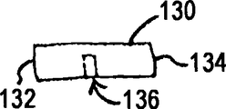
Figure 10 A-10C shows perspective view, vertical view and the side view of another kind of exemplary indicia thing respectively;
Figure 11 A-11C shows perspective view, vertical view and the side view of another exemplary indicia thing respectively;
Figure 12 A-12C shows perspective view, vertical view and the side view of another exemplary indicia thing respectively;
Figure 13 A-13C shows perspective view, vertical view and the side view of another kind of exemplary indicia thing respectively;
Figure 14 A-14C shows perspective view, vertical view and the side view of another exemplary indicia thing respectively;
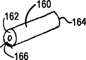
Figure 15 A-15C shows perspective view, vertical view and the side view of another exemplary indicia thing respectively;
Figure 16 shows the cutaway view of parts that is used for marker element is inserted into the exemplary device of label body;
Figure 17 shows device among Figure 16 in the first exemplary operational phase;
Figure 18 shows device among Figure 16 in the second exemplary operational phase; And
Figure 19 shows device among Figure 16 in the 3rd exemplary operational phase.
The specific embodiment
The following explanation of some embodiments of the invention be shall not be applied to limit the scope of the invention.By following explanation, it is very clear that other embodiment of the present invention, feature, aspect, embodiment and advantage can become to those skilled in the art, below explanation be provide by way of example be used for carrying out a kind of of optimization model of the present invention.As being recognized, the present invention can also realize other different and tangible aspects, and all these does not deviate from the present invention.Therefore, drawing and description should be thought exemplary with nonrestrictive in itself.
As shown in Figure 1, exemplary label applicator 10 comprises elongated trocar sheath 12, is formed with transverse opening 14 near the far-end of this elongated trocar sheath 12.The far-end of sleeve pipe 12 comprises the tip 22 of sealing.Near-end at sleeve pipe 12 is provided with handle 16.Sleeve pipe 12 and most advanced and sophisticated 22 can be formed by high-performance thermoplastic polyamide elastomer (PEBAX), any suitable polymer, metal or any other suitable material (comprising their combination).Bar 18 is inserted in the sleeve pipe 12 and can translation in sleeve pipe 12.Bar 18 has enough rigidity so that label 30 is released by opening 14, will illustrate in further detail as following.But in this example, bar 18 and sleeve pipe 12 are flexible.Be provided with plunger 20 in the proximal end of bar 18, it is used for making bar 18 distad to be promoted at sleeve pipe 12.Particularly, user can be with two finger grip handles 16, and can use the thumb of the same hand to promote plunger 20, thereby user can be used one-handed performance applicator 10.Spring (not shown) or miscellaneous part can be provided with around bar 18, with proximad bias stem 18.
A kind of exemplary usage of label applicator 10 has been shown among Fig. 2.Particularly, Fig. 2 far-end of showing label applicator 10 is arranged in the outer needles 24 of biopsy device.Outer needles 24 has puncture tip organized 26 and is positioned at the transverse opening 28 of described most advanced and sophisticated 26 nearsides.In the present example, pin 24 and applicator 10 are constructed such that opening 28 substantial registration when sleeve pipe 12 is inserted in the pin 24 of the opening 14 and the pin 24 of sleeve pipe 12.In other words, the opening 14 of sleeve pipe 12 makes label 30 to place by two openings 14,28 with respect to opening 28 location of pin 24.In order to place label 30, user actuating plunger 20 is drive rod 18 distad.The tip 22 of label applicator 10 comprises the inclined surface 23 towards nearside, and when bar 18 was distad driven, this inclined surface 23 forced label 30 outwards to enter biopsy site by opening 14,28.
The label 30 of this example comprises label body 32 and identification element 34.In some forms, label body 32 under ultra sonic imaging as seen, identification element 34 in other imaging forms MRI and X ray under as seen.For example, label body 32 can be by bovine collagen, cellulose, polylactic acid/polyglycolic acid (PLA/PGA), glycoprene, gel-like material hydrogel for example, and/or any other suitable material, comprises that their compositions forms.In addition, label body 32 can be biodegradable or biological absorbable, perhaps can have other characteristics.Identification element 34 can comprise titanium wire, bead or other structures.Certainly, identification element 34 can use any other material, comprises the combination of described material.In some forms, label body 32 is formed by rectangle collagen pad, and this rectangle collagen pad folds and/or rolls around titanium identification element 34, to form label 30 cylindraceous basically.Then, in this example, label applicator 10 is loaded with inside compact token thing 30 radially before placing label 30 being inserted in the sleeve pipe 12.Certainly, label 30 can have various alternate structures, can form in order to crossing various technology, and can use by various other modes.Several only for illustrative purposes embodiment that below will describe this modification in further detail.
I. the modification of label applicator far-end
In view of herein instruction is appreciated that label applicator 10 can adopt various ways and have various structures.Below will describe some such structures in further detail, and other such structure can be expected under the instruction of this paper for those of ordinary skills.
As shown in Figure 3, according to a kind of only be exemplary modification, label applicator 10 can be included in the inclined surface 40 towards the distally on the far-end of bar 18.In view of instruction herein, the suitable angle of inclined surface 40 can be expected for those of ordinary skills.In the present example, most advanced and sophisticated 22 have the flat basically inner face 42 towards nearside.At user actuating plunger 20 and distad during drive rod 18, inclined surface 40 engages labels 30.When label 30 inclined surface 40 of engaging lever 18 at one end, when the flat inner face 42 of other end engaging tip 22, label 30 is outwards ordered about (for example, radially outside) and is entered the intravital position of patient via opening 14 from sleeve pipe 12.
Fig. 4 shows the similar modification of label applicator 10.In the present example, label applicator 10 is also included within the inclined surface 40 on the far-end of bar 18.In addition, most advanced and sophisticated 22 have flat basically inner face 42.But in the present example, label 30 has angled end 36.In view of instruction herein, the suitable angle of angled end 36 can be expected for those of ordinary skills.Angled end 36 can form in many ways.For example, angled end 36 can be taper or truncated cone shape basically.Alternatively, angled end 36 can by two or more on common limit, the plane assembled of face or point forms.In view of instruction herein, the alternate manner that the angled end 36 of label 30 can be set can be expected for those of ordinary skills.
In the present example, angled end 36 is configured to interact with the inclined surface 40 of bar 18.Particularly, at user actuating plunger 20 and distad during drive rod 18, inclined surface 40 engages the angled end 36 of labels 30.When the inclined surface 40 of label 30 at angled end 36 1 end engaging levers 18, when the flat inner face 42 of other end engaging tip 22, label 30 is outwards ordered about (for example, radially outside) and is entered into the intravital position of patient from sleeve pipe 12 via opening 14.
Fig. 5 shows the another kind of modification of label applicator 10.In the present example, bar 18 has flat basically far-end 44, and this far-end 44 is arranged essentially parallel to most advanced and sophisticated 22 flat inner face 42.Alternatively, far-end 44 and/or inner face 42 can be tilt or have some other structures.Label 30 in the present example has concave regions 38 at its substantial middle place.Concave regions 38 can form around the whole circumference of label 30.Alternatively, concave regions 38 can be formed by two or more general plane of assembling at common circumferential zones place.In view of instruction herein, can construct the alternate manner of concave regions 38 and can expect for those of ordinary skills.Concave regions 38 can or otherwise remove material by cutting material from label body 32 and form.Alternatively, concave regions 38 can form by the central authorities of compression or curling label body 32.In view of instruction herein, the alternate manner that can form concave regions 38 can be expected for those of ordinary skills.
In the present example, label 30 is constructed such that when bar 18 is distad driven, and is squeezed in the far-end 44 of bar 18 and the label 30 between most advanced and sophisticated 22 the inner face 42, and label body 32 is crooked or buckle (buckle) at concave regions 38 places.This bending can cause label 30 " ejection (pop out) " opening 14, leaves sleeve pipe 12 thus and enters in the biopsy site.Additionally or alternatively, this bending can cause label body 32 to fragment into two halves and " ejection " opening, leaves sleeve pipe 12 thus and enters in the biopsy site.
Fig. 6 shows the another kind of modification of label applicator 10.In this example, bar 18 has flat basically far-end 44, is similar to the bar 18 shown in Fig. 5.Most advanced and sophisticated 22 have the surface 23 of inclination, are similar to the tip 22 shown in Fig. 2.But, in the present example, be provided with thin plastic sheath 50 around sleeve pipe 12.Especially, sheath 50 is around the outer setting of the sleeve pipe 12 that comprises tip 22.The part of sheath 50 caves in opening 14, and so that chamber 52 to be provided, label 30 is contained in the chamber 52 and in the outside of sheath 50.When bar 18 was distad driven, the far-end 44 of bar 18 engaged sheath 50, and this outwards drives label 30.In addition or replace bar 18 distal motion placing label 30, the part of sheath 50 can the proximad withdrawal with outside driving label 30.For example, collar (not shown) or other parts can be fixed to sheath 50, for example the handle 16 of close label applicator 10.(for example by the proximad pulling collar) makes the withdrawal of sheath 50 proximads can cause sheath 50 to become and strains basically.Thisly make the rate of tension increase of sheath 50 can outwards draw chamber 52, outwards drive label 30 thus.Certainly, sheath 50 can multiple alternate manner setting and use, and can combine with other any variations about label applicator 10 and label 30 described herein.
Fig. 7 shows another modification of label applicator 10.In this example, bar 18 has flat basically far-end 44, is similar to the bar 18 shown in Fig. 5 to 6.But in this example, sleeve pipe 12 has open and crooked far-end 60.The far-end 60 of sleeve pipe 12 is constructed such that when bar 18 is distad driven the far-end 44 of bar 18 is released label 30 and entered in the intravital biopsy site of patient or other position by the far-end 60 of the opening of sleeve pipe 12.Bar 18 can have enough flexible, moves with at least a portion of the curvature of the far-end 60 of following sleeve pipe 12 in sleeve pipe 12 when bar 18 is distad driven basically.Alternatively, sleeve pipe 12, label 30 and/or bar 18 can be constructed such that bar 18 needn't follow the arbitrary portion of the curvature of far-end 60 and move to place label 30.
In addition, the far-end 60 of sleeve pipe 12 can have enough elasticity distad advances by biopsy needle 24 to allow sleeve pipe 12, makes that far-end 60 becomes straight relatively when sleeve pipe 12 is advanced in biopsy needle 24.When far-end 60 arrived the opening 28 of biopsy needle 24, far-end 60 can outwards " be upspring " subsequently owing to the elasticity of its material.Therefore, far-end 60 can form curved configuration again when arriving the opening 28 of biopsy needle 24.In some forms, the far-end 60 of sleeve pipe 12 is molded as curved configuration, so that this elasticity to be provided.In view of instruction herein, the alternate manner of structure and formation far-end 60 can be expected for those of ordinary skills.In addition, in view of instruction herein, suitable radius of curvature or other form for curvature of far-end 60 can be expected for those of ordinary skills.
Fig. 8 shows another form of label applicator 10.In this example, sleeve pipe 12 comprises the sheet spring 60 near most advanced and sophisticated 22.When sheet spring 60 as shown in Figure 8 during the indent archwise, sheet spring 60 forms chambers 62, is provided with label 30 in this chamber 62.Sheet spring 60 can be by forming with the remainder identical materials that forms sleeve pipe 12 (for example, PEBAX, any suitable plastic material etc.), and/or can form as one with sleeve pipe 12.Alternatively, sheet spring 60 can be individually formed (for example, being formed by metal, some other plastic materials etc.) and be fixed to sleeve pipe 12.
As shown in Figure 8, sheet spring 60 is in the spill configuration, forms chamber 62 and deposit potential energy.Yet when fully activating, sheet spring 60 outside " upspringing " forms the convex configuration, thus label 30 is placed in the intravital biopsy site of patient or other position.With dashed lines 64 shows a kind of exemplary convex configuration of sheet spring 60 among Fig. 8.
The braking plate spring 60 in many ways, for example by sheet spring 60 is buckled.For example, can use distad drive rod 18 of plunger 20, the far-end 44 with bar 18 is driven in the sheet spring 60 thus, with braking plate spring 60.Certainly, also can use bar 18 with inclined surface 40.Alternatively, can (for example by distad driving handle 16) distad drive whole sleeve pipe 12, be driven in the proximal side 27 at tip 36 of pin 24 of biopsy device most advanced and sophisticated 22 thus.This tip 22 is driven into can cause sheet spring 60 to be buckled in the proximal side 27, thus sheet spring 60 is actuated into convex configuration.Therefore, except other parts, applicator 10 can not be provided with bar 18 fully.In view of instruction herein, can be used for braking plate spring 60 and can expect for those of ordinary skills with the alternate manner of placing label 30.
Any variations of aforementioned tagging material applicator 10 can engage with biopsy device in every way.Particularly, biopsy device can be formed at its at least a portion and still be inserted in the intravital label applicator 10 that receives simultaneously of patient.In other words, biopsy device can be used to obtain tissue samples, and label applicator 10 can be introduced and needn't draw back the biopsy device in tissue or biopsy device inserted in the tissue again by biopsy device.For example, biopsy device can have opening in its case side, to allow user sleeve pipe 12 is inserted through the side opening of biopsy device and passes through pin 24.Biopsy device also can comprise the passage (for example with the coaxially aligned passage of pin 24) in the portions of proximal that is formed on biopsy device, thereby allows user to be inserted in the pin 24 of biopsy device by the sleeve pipe 12 of proximal channel with label applicator 10.One of this proximal channel only for exemplary example be disclosed in submitted on November 20th, 2007 be entitled as " Deployment Device Interface for Biopsy Device ", serial number is in U.S.'s non-provisional application of No.11/942791, the content of this U.S.'s non-provisional application is incorporated in this by reference.In view of instruction herein, the alternate manner that label applicator 10 can be used in combination with biopsy device can be expected for those of ordinary skills.Alternatively, label applicator 10 can be independent of biopsy device to be used, and perhaps uses in other operation.
II. the modification of label body
In view of herein instruction is further appreciated that label 30 can adopt various ways and have multiple structure.Below will describe some such structures in further detail, and other such structure can be expected under the instruction of this paper for those of ordinary skills.In the example of some forms of describing in further detail shown in Fig. 9-15 and hereinafter, the label body forms the collagen pin, and identification element is inserted into or otherwise be arranged in the collagen pin.But, should be understood that, can use various other materials to form the label body.In addition, should be understood that, identification element except or replace being arranged in the label body, can also be arranged on the label body exterior.
Shown in Fig. 9 A-9C, label body 100 comprises the bovine collagen pin.Label body 100 has cylindrical form basically, does not form otch or groove therein.Identification element 34 can be inserted in the label body 100 and/or be positioned at label body 100 outsides (for example, be wrapped in label body 100 around etc.).For example, can use the following insertion device of describing in further detail with reference to Figure 16-19 200 or use any other proper device or technology that identification element 34 is inserted in the label body 100.In some forms, after identification element 34 was inserted in the label body 100 and/or centers on label body 100 location, label body 100 was radially inwardly compressed.Also can compress the two ends 102,104 of label body 100.Then, label body 100 is positioned in the sleeve pipe 12 of label applicator 10, prepares to be placed in the intravital biopsy site of patient or other position.In view of instruction herein, the suitable length of label body 100 and diameter and the suitable method that label body 100 is made collagen pin or other form can be expected for those of ordinary skills.
Figure 10 A-10C shows another kind of exemplary label body 110.In this example, label body 110 also comprises the collagen pin, is similar to above-mentioned label body 100, but also can use other above-mentioned material.But label body 110 also has the longitudinal slot 116 that is formed on wherein.Slit 116 longitudinally extends to the other end 114 of label body 110 from an end 112 of label body 110; And radially extend to the central authorities of label body 110 from the outer surface of label body 110.Slit 116 can or use any other suitable technology to form by cut mark thing body 110, curling label body 110.As illustrating best among Figure 10 C, slit 116 provides and eats profile like bean people (PAC-MAN, the video game image) feature class for label body 110.
Figure 11 A-11C shows the another kind of exemplary label body 120 that only is.In this example, label body 120 also comprises the collagen pin, is similar to above-mentioned label body 100, but also can use other above-mentioned material.In label body 120, be formed with groove 126.The longitudinal boundary of groove 126 makes groove 126 not extend along the total length of label body 120 between the end 122,124 of label 120.Though shown in groove 126 be in substantial middle place between the end 122,124, groove 126 can have any other suitable lengthwise position.Groove 126 radially extends to the central authorities of marker body 120 from the outer surface of marker body 120.Alternatively, groove 126 can pass completely through label body 120 (for example, the full diameter along label body 120 extends).
Groove 126 can or utilize any other suitable technology to form by cut mark thing body 120, punch mark thing body 120.Groove 126 in this example provides a zone, and identification element 34 can insert or otherwise be positioned in this zone.In some forms, remove label body 120 (not shown) to form groove 126 from label body 120, this piece label body relays in the return-enclosure 126 after identification element 34 is placed in the groove 126.In addition or alternatively, label body 120 can be compressed before or after identification element 34 is positioned in the groove 126 as described above.In view of instruction herein, one or more identification elements 34 can be able to be expected for those of ordinary skills with label body 120 bonded other suitable modes.
Figure 12 A-12C shows another and only is exemplary label body 130.In this example, label body 130 also comprises the collagen pin, is similar to above-mentioned label body 100, but also can use other above-mentioned material.Label body 130 is formed with transverse opening 136 therein.Transverse opening 136 and radially extends to the central authorities of label body 130 from the outer surface of label body 130 between the end 132,134 of label body 130.Though opening 136 is shown in the substantial middle between the end 132,134, opening 136 can have any other suitable lengthwise position.
Opening 136 can be by to 130 borings of label body, punching press or jab or utilize any other suitable technology to form.Opening 136 in this example provides a zone, and identification element 34 can insert or otherwise be positioned in this zone.Identification element 34 can laterally or with respect to label body 130 longitudinally be introduced in opening 136 with respect to label body 130.Label body 130 can be compressed before or after identification element 34 is positioned in the opening 136 as described above.In view of instruction herein, one or more identification elements 34 can be able to be expected for those of ordinary skills with label body 130 bonded other suitable modes.
Figure 13 A-13C shows another and only is exemplary label body 140.In this example, label body 140 also comprises the collagen pin, is similar to above-mentioned label body 100, but can use other above-mentioned material.In addition, label body 140 has the transverse opening 146 that is positioned between the end 142,144, is similar to aforesaid label body 130.But different with the opening 136 of label body 130, the opening 146 of label body 140 extends through label body 140.In addition, label body 140 is substantially the same with label body 130, and mode incorporation of markings element 34 that can be identical as above-mentioned label body 130.
Figure 14 A-14C shows another exemplary label body 150.In this example, label body 150 also comprises the collagen pin, is similar to above-mentioned label body 100, but can use other above-mentioned material.Label body 150 is formed with longitudinal opening 156 therein.Longitudinal opening 156 extends to the central authorities of label body 150 from an end 152 of label body 150, and does not arrive the other end 154 of label body 150.Though opening 156 is depicted as along the axis location that is limited by label body 150, opening 156 can have any other suitable position.
Opening 156 can be by to 150 borings of label body, punching press or jab or utilize any other suitable technology to form.Opening 156 in this example provides a zone, and identification element 34 can insert or otherwise be positioned in this zone.Identification element 34 can laterally or with respect to label body 150 longitudinally be introduced in opening 156 with respect to label body 150.Label body 150 can be compressed before or after identification element 34 foot positions are in opening 156 as described above.In view of instruction herein, one or more identification elements 34 can be able to be expected for those of ordinary skills with label body 150 bonded other suitable modes.
Figure 15 A-15C shows another and only is exemplary label body 160.In this example, label body 160 also comprises the collagen pin, is similar to above-mentioned label body 100, but can use other above-mentioned material.In addition, label body 160 is formed with longitudinal opening 166 therein, is similar to above-mentioned label body 150.But different with the opening 156 of label body 150, the opening 166 of label body 160 runs through the whole length extension (that is 162 164 extensions to the end from the end) of label body 160.In addition, label body 160 is substantially the same with label body 150, and can the mode incorporation of markings element 34 identical with above-mentioned label body 150.
Previous example comprises in the different possible modification of many kinds of label body 32 some.In view of instruction herein, some other modification of label body 32 can be expected for those of ordinary skills.In addition, though single marking thing 30 is loaded in the label applicator 10 in this example, should be appreciated that a plurality of labels 30 can be loaded in the label applicator 10.For example, each label 30 in described a plurality of labels 30 can have the feature different with other label 30 in described a plurality of labels 30 (for example, but different materials, different sizes, different shapes, different imagings etc.).Alternatively, some or all labels 30 in these multiple labels can have substantially the same feature (if not having similar characteristics).A plurality of labels 30 in label applicator 10 can be placed in the intravital identical biopsy site of patient or other position, perhaps can be placed on the intravital diverse location of patient.
III. label is inserted in the label body
In view of also being appreciated that, herein instruction can utilize various devices and technology that identification element 34 is arranged in the label body 30.A kind ofly only will hereafter be described in more detail, and can expect for those of ordinary skills in view of other device and technology of herein instruction for exemplary device 200 and technology.
Shown in Figure 16-19, the device 200 that is used for identification element 34 is inserted into label body 32 comprises substrate 210, connector 230, needle member 250 and plunger 270.Substrate 210 comprises base portion 212 and cervical region 214.Plug open 216 is formed in the base portion 212.Plug open 216 is configured to receive connector 230 as following as described in will be in further detail.Label opening 218 also is formed in the base portion 212.Label opening 218 is configured to receive marker body 32 as following as described in will be in further detail.In this example, the diameter of plug open 216 is bigger than the diameter of label opening 218, but in other form, label opening 218 can have bigger diameter, and perhaps opening 216,218 can have the diameter that equates basically.Cervical region 214 is formed with neck opening 220 therein, and has chamfered edge 222.Certainly, can be cut sth. askew in edge 222, and can rounded angle, meet at right angles or have any other suitable structure.In addition, though opening 216,218,220 is coaxially aimed in this example, opening 216,218 and 220 can have any other suitable relation.For example, label opening 218 can be substantially perpendicular to neck opening 220.
The hollow needle 256 that needle member 250 in this example comprises main body 252, open top 254 and is positioned in the main body 252 and extends from main body 252.Open top 254 forms the funnel-shaped structure of the inside opening that leads to hollow needle 256.Holding screw 258 is transverse to pin 256 location, and operationally locking pin 256 with respect to the lengthwise position of main body 252.In other words, pin 256 is adjustable with respect to the lengthwise position of main body 252 in this example.Certainly, can omit holding screw 258, make that pin 256 is fixed basically with respect to the lengthwise position of main body 252, perhaps can utilize any other suitable structure.
In this example, the diameter of needle member 250 is substantially equal to or less than the diameter of neck opening 220.Therefore, needle member 250 can be inserted in the neck opening 220.In addition, the length of neck opening 220, main body 252 and pin 256 is designed such that pin 256 extends in the label opening 218 when needle member 250 is inserted in the neck opening 220 as shown in figure 18.Cooperation between needle member 250 and the neck opening 220 can be to closely cooperate or loose cooperation as required.Alternatively, needle member 250 and substrate 210 can also have any other suitable relation by tool.
In this example, the diameter of hollow interior section 274 is substantially equal to or greater than the diameter of cervical region 214.The diameter of pin 276 is less than the internal diameter of hollow needle 256.Therefore, plunger 270 can link to each other with cervical region 214, makes hollow interior section 274 receive cervical region 214.Chamfered edge 222 can help this connection.In addition, cervical region 214, hollow interior section 274 and the length of selling 276 are designed such that pin 276 extends through pin 256 when plunger 270 links to each other with cervical region 214 as shown in figure 19.Especially, in this example, pin 276 extends by pin 256 fully.Cooperation between plunger 270 and the cervical region 214 can be to closely cooperate or loose cooperation as required.Alternatively, plunger 270 and substrate 210 can have any other suitable relation.
Figure 17-19 shows a series of exemplary use step that label inserts device 200.Though should be noted that to show marker body 32 among Figure 17-19 respectively that Figure 18-the 19th show marker body 32 with the form of cutaway view, and Figure 17 is not.At first, as shown in figure 17, connector 230 can be positioned in the substrate 210.After connector 230 is positioned in the substrate 210, label body 32 is inserted in the label opening 218, also as shown in figure 17.This cooperation between label body 32 and the label opening 218 can be to closely cooperate or loose cooperation as required.Alternatively, label body 32 and substrate 210 can have any other suitable relation.
Then, as shown in figure 18, needle member 250 is engaged with substrate 210.Identification element 34 can be introduced by needle member 250 then.Particularly, can make identification element 34 fall into open top 254.In this example, the open top 254 with funnel-like configuration can be as the guiding piece of identification element 34, with the inside opening guiding of identification element 34 towards hollow needle 256.The size of the inside opening of hollow needle 256 can be designed to the size of greater than flag element 34 slightly, thereby allows identification element 34 by hollow needle 256.Before being inserted into needle member 250 in the neck opening 220, the lengthwise position of pin 256 can be adjusted to and make that when needle member 250 was inserted in the neck opening 220, the free tip of pin 256 was arranged in the substantial middle place of the label body 32 that is positioned at label opening 218.Alternatively, the tip of pin 256 can be longitudinal positioning of the position of the central authorities of no show label body 32 still or surpass the position of the central authorities of label body 32 slightly.
Then, engage with substrate 210 as shown in figure 18 and after identification element 34 fell into open top 254, plunger 270 can link to each other with cervical region 214 as shown in figure 19 at needle member 250.Particularly, pin 276 can promote identification element 34 fully by in pin 256 and the arrival label body 32.The lengthwise position that depends on pin 256 and pin 276, this can cause identification element 34 to be positioned at the substantial middle place of label body 32.Then, can make plunger 270 and needle member 250 break away from substrate 210, draw back pin 176 and pin 256 from label body 32 thus, identification element 34 is stayed in the label body 32.
Then, can remove label body 32 from substrate 210.For example, can promote the head 232 of connector 230 up, make the post 234 of connector 230 upwards drive label body 32 and enter neck opening 220, label body 32 can easily be removed (for example pull out, pour out etc.) in this neck opening 220.Alternatively, can remove connector 230, and can use and jab apparatus and upwards promote label body 32 and make it pass through neck opening 220 to discharge; Perhaps promoting label body 32 downwards makes it pass through plug open 216 discharges.In view of instruction herein, label body 32 can be able to be expected for those of ordinary skills from the alternate manner that label insertion device 200 removes.
Should be understood that, can change the method that label inserts device 200 and usage flag thing insertion device 200 in many ways.Only as an example, can save connector 230.For example, plug open 216 can be substituted by the opening of diameter less than the diameter of label body 32.This alternate opening can be enough little, moves downward by essential part 212 with limit markers thing body; But want enough big, discharge by neck opening 220 to allow apparatus to insert to jab label body 32 by described opening.
The another kind that the thing that serves as a mark inserts device 200 only is the modification of illustrative example, and label opening 218 can laterally be positioned in the substrate 210.In other words, label opening 218 may be oriented to and makes that pin 256 and pin 276 can be laterally but not longitudinally enter label body 32.Also should be understood that, label insert device 200 can with push machinery or other automatic system links to each other, thus in the use automatization that makes label insertion device 200 at least to a certain extent.In view of instruction herein, the alternate manner that can change label insertion device 200 and use thereof can be expected for those of ordinary skills.
Embodiments of the present invention can be applied to also be used for the auxiliary surgical operation of robot in conventional endoscope and the open surgical apparatus.
The embodiment of device disclosed herein can be designed to abandon after once using, and perhaps can be designed to repeatedly use.In any case or in both cases, embodiment can be included in and at least once use the back to repair in order to reusing.Reparation can comprise the combination of the demounting procedure of device, and cleaning or replacement special order are assembled subsequently subsequently.Particularly, the embodiment of device can be dismantled, and can any bonded mode replaces or pull down the special order or the parts of the arbitrary number of device selectively.Along with cleaning and/or the replacement to specific features, assembling before the embodiment of device can be about to carry out surgical operation at the restoration facilities place or by surgery team is so that use subsequently.It will be appreciated by those skilled in the art that and to use the various technology that are used to dismantle, clean/replace and assemble to come prosthetic device.The good device of the use of these technology and the reparation that is obtained all within the scope of the present invention.
As just example, embodiment as herein described can be handled before operation.At first, obtain new or exhausted apparatus and cleaning as required.Can sterilize to apparatus then.In a kind of sterilization technology, apparatus is placed in the sealed container (for example plastics or TYVEK bag) of sealing.Afterwards, container and apparatus can be placed in the radiation area that can penetrate container, for example gamma radiation district, x ray district or high energy electron district.Radiation can kill on the apparatus and container in antibacterial.Sterilized instrument can be stored in sterilization container subsequently.Sealed container can keep instrument sterile, is opened in medical facilities up to container.Can also use other technologies known in the art (including but not limited to β or gamma radiation, ethylene oxide,1,2-epoxyethane or steam) that device is sterilized.
Though illustrated and described various embodiment of the present invention, without departing from the present invention,, can finish further coupling to method and system as herein described by those skilled in the art's suitable modification.In these possible modifications several are referred, and other modification it may occur to persons skilled in the art that.For example, the above embodiments, embodiment, geometric figure, material, size, ratio, step and similar parameters are schematic rather than necessary.Therefore, scope of the present invention should take in the accompanying Claim book, and is not to be construed as limiting shown in description and the accompanying drawing and the details of described structure and operation.
Claims (10)
1. one kind is used for label is placed into the intravital apparatus of patient, and described apparatus comprises:
(a) have the elongated sleeve pipe of near-end and far-end, described sleeve pipe also is included in the most advanced and sophisticated of described far-end and at the transverse opening of described most advanced and sophisticated nearside;
(b) be arranged on elongated pusher in the described sleeve pipe, wherein, described pusher is formed at motion longitudinally in the described sleeve pipe, and described elongated pusher has the far-end of inclination; With
(c) be arranged on label in the described sleeve pipe, wherein, described label is formed at far-end by the described inclination of described pusher to be left from described transverse opening when promoting.
2. apparatus according to claim 1, wherein, described telescopic tip comprises flat basically proximal side.
3. apparatus according to claim 2, wherein, described label is positioned between the proximal side at the far-end of described inclination and described tip.
4. apparatus according to claim 1, wherein, described label has first end towards the far-end of the described inclination of described pusher, and described first end of described label comprises the surface of one or more inclinations.
5. apparatus according to claim 4, wherein, described first end of described label is taper or truncated cone shape basically.
6. apparatus according to claim 4, wherein, described label has second end, and described second end is flat basically.
7. apparatus according to claim 1, wherein, described pusher comprises bar and is positioned at the plunger of the proximal end of described bar.
8. apparatus according to claim 1, wherein, at least a portion of described elongated pusher is extended from described elongated telescopic near-end proximad.
9. apparatus according to claim 1, wherein, described elongated telescopic size can be inserted through the biopsy needle inside of hollow.
10. apparatus according to claim 1 also comprises the sheath that is provided with around described elongated sleeve pipe, and described sheath limits and is configured for the chamber that holds described label.
Applications Claiming Priority (2)
| Application Number | Priority Date | Filing Date | Title |
|---|---|---|---|
| US12/036,521 US8068895B2 (en) | 2008-02-25 | 2008-02-25 | Biopsy site marker deployment instrument |
| US12/036,521 | 2008-02-25 |
Publications (1)
| Publication Number | Publication Date |
|---|---|
| CN101518466A true CN101518466A (en) | 2009-09-02 |
Family
ID=40548764
Family Applications (1)
| Application Number | Title | Priority Date | Filing Date |
|---|---|---|---|
| CN200910118214A Pending CN101518466A (en) | 2008-02-25 | 2009-02-25 | Biopsy site marker deployment instrument |
Country Status (6)
| Country | Link |
|---|---|
| US (1) | US8068895B2 (en) |
| EP (1) | EP2092906A3 (en) |
| CN (1) | CN101518466A (en) |
| AU (1) | AU2009200662A1 (en) |
| BR (1) | BRPI0901510A2 (en) |
| CA (1) | CA2655588A1 (en) |
Cited By (6)
| Publication number | Priority date | Publication date | Assignee | Title |
|---|---|---|---|---|
| CN104605897A (en) * | 2015-01-04 | 2015-05-13 | 中国人民解放军第四军医大学 | Mechanism capable of marking tumor boundary used for biopsy needle |
| CN105073022A (en) * | 2013-03-15 | 2015-11-18 | 德维克医疗产品公司 | Biopsy site marker releaser |
| CN105473098A (en) * | 2013-08-15 | 2016-04-06 | 直观外科手术操作公司 | Systems and methods for medical procedure confirmation |
| CN105749300A (en) * | 2016-02-24 | 2016-07-13 | 赛昂国际医疗技术(中国)有限公司 | Marker and transferring device thereof |
| CN110876630A (en) * | 2018-09-05 | 2020-03-13 | 新加坡国立大学 | Transurethral prostate sampling device and method of making same |
| CN116672035A (en) * | 2023-05-30 | 2023-09-01 | 无锡海斯凯尔医学技术有限公司 | Conveying structure, marking device and rotary cutting equipment |
Families Citing this family (15)
| Publication number | Priority date | Publication date | Assignee | Title |
|---|---|---|---|---|
| CA2494377C (en) * | 2002-08-01 | 2012-09-25 | James E. Selis | Biopsy devices and methods |
| US8075568B2 (en) | 2004-06-11 | 2011-12-13 | Selis James E | Biopsy devices and methods |
| EP3106089B1 (en) | 2009-06-26 | 2020-12-02 | Cianna Medical, Inc. | System for localizing markers or tissue structures within a body |
| US9386942B2 (en) * | 2009-06-26 | 2016-07-12 | Cianna Medical, Inc. | Apparatus, systems, and methods for localizing markers or tissue structures within a body |
| US9414816B2 (en) * | 2011-06-23 | 2016-08-16 | Devicor Medical Products, Inc. | Introducer for biopsy device |
| US10391291B2 (en) | 2012-10-02 | 2019-08-27 | Robert F. Wallace | Implant insertion system |
| US10683119B2 (en) | 2014-05-23 | 2020-06-16 | Merit Medical Systems, Inc. | Marker element, device for making a marker element, and method for making a marker element |
| US10166084B2 (en) * | 2014-11-06 | 2019-01-01 | Devicor Medical Products, Inc. | Spring-ejected biopsy marker |
| US10646208B2 (en) * | 2015-05-06 | 2020-05-12 | Devicor Medical Products, Inc. | Marker delivery device for use with MRI breast biopsy system |
| KR20180082444A (en) | 2015-11-11 | 2018-07-18 | 데비코어 메디컬 프로덕츠, 인코포레이티드 | How to Place Marker Delivery Devices and Markers |
| WO2017083417A1 (en) | 2015-11-12 | 2017-05-18 | Devicor Medical Products, Inc. | Marker delivery device and method of deploying a marker |
| US10335124B1 (en) | 2016-02-29 | 2019-07-02 | Devicor Medical Products, Inc. | Marker delivery device with adaptor for biopsy site marking and method of use thereof |
| CN110267600B (en) * | 2017-02-06 | 2022-12-20 | 设备与设计有限责任公司 | Systems, methods, and devices for integrated tissue sampling and tissue marker placement |
| US11266481B2 (en) | 2018-10-12 | 2022-03-08 | Hologic, Inc. | Tissue localization marker with D-shaped cross-section |
| WO2020243386A1 (en) * | 2019-05-30 | 2020-12-03 | Devicor Medical Products, Inc. | Shape memory marker deployment device |
Citations (2)
| Publication number | Priority date | Publication date | Assignee | Title |
|---|---|---|---|---|
| US5906599A (en) * | 1995-11-09 | 1999-05-25 | Intermed, Inc. | Device for delivering biological agents |
| US20070142725A1 (en) * | 2005-12-16 | 2007-06-21 | Hardin Terry D | Biopsy site marker deployment device |
Family Cites Families (42)
| Publication number | Priority date | Publication date | Assignee | Title |
|---|---|---|---|---|
| US421072A (en) * | 1890-02-11 | Surgical | ||
| US2828744A (en) * | 1956-02-13 | 1958-04-01 | Hirsch Sidney | Flexible needle for use in intravenous therapy |
| US5002548A (en) * | 1986-10-06 | 1991-03-26 | Bio Medic Data Systems, Inc. | Animal marker implanting system |
| US5024727A (en) * | 1986-10-06 | 1991-06-18 | Bio Medic Data Systems, Inc. | Method of forming an animal marker implanting system |
| US4787384A (en) * | 1986-10-06 | 1988-11-29 | Bio Medic Data System, Inc. | Animal marker implanting system |
| US5526822A (en) * | 1994-03-24 | 1996-06-18 | Biopsys Medical, Inc. | Method and apparatus for automated biopsy and collection of soft tissue |
| CA2199864C (en) * | 1994-09-16 | 2006-06-20 | Seth A. Foerster | Methods and devices for defining and marking tissue |
| DE19541266A1 (en) | 1995-11-06 | 1997-05-07 | Bayer Ag | Method and device for carrying out chemical reactions using a microstructure lamella mixer |
| US5853366A (en) * | 1996-07-08 | 1998-12-29 | Kelsey, Inc. | Marker element for interstitial treatment and localizing device and method using same |
| US6270464B1 (en) * | 1998-06-22 | 2001-08-07 | Artemis Medical, Inc. | Biopsy localization method and device |
| JP4077951B2 (en) * | 1998-01-14 | 2008-04-23 | 株式会社ルネサステクノロジ | Defect analysis method, recording medium, and process management method |
| US6455186B1 (en) | 1998-03-05 | 2002-09-24 | Black & Decker Inc. | Battery cooling system |
| US6347241B2 (en) * | 1999-02-02 | 2002-02-12 | Senorx, Inc. | Ultrasonic and x-ray detectable biopsy site marker and apparatus for applying it |
| US6161034A (en) * | 1999-02-02 | 2000-12-12 | Senorx, Inc. | Methods and chemical preparations for time-limited marking of biopsy sites |
| US7063681B1 (en) * | 1998-04-23 | 2006-06-20 | Alza Corporation | Trocar for inserting implants |
| US6220248B1 (en) * | 1998-10-21 | 2001-04-24 | Ethicon Endo-Surgery, Inc. | Method for implanting a biopsy marker |
| US6356782B1 (en) * | 1998-12-24 | 2002-03-12 | Vivant Medical, Inc. | Subcutaneous cavity marking device and method |
| US6371904B1 (en) * | 1998-12-24 | 2002-04-16 | Vivant Medical, Inc. | Subcutaneous cavity marking device and method |
| US6270472B1 (en) * | 1998-12-29 | 2001-08-07 | University Of Pittsburgh Of The Commonwealth System Of Higher Education | Apparatus and a method for automatically introducing implants into soft tissue with adjustable spacing |
| US6862470B2 (en) * | 1999-02-02 | 2005-03-01 | Senorx, Inc. | Cavity-filling biopsy site markers |
| US7983734B2 (en) * | 2003-05-23 | 2011-07-19 | Senorx, Inc. | Fibrous marker and intracorporeal delivery thereof |
| US6725083B1 (en) * | 1999-02-02 | 2004-04-20 | Senorx, Inc. | Tissue site markers for in VIVO imaging |
| US20080039819A1 (en) * | 2006-08-04 | 2008-02-14 | Senorx, Inc. | Marker formed of starch or other suitable polysaccharide |
| US6086544A (en) * | 1999-03-31 | 2000-07-11 | Ethicon Endo-Surgery, Inc. | Control apparatus for an automated surgical biopsy device |
| US6161304A (en) * | 1999-10-05 | 2000-12-19 | M&R Printing Equipment, Inc. | Dryer assembly |
| US6450938B1 (en) * | 2000-03-21 | 2002-09-17 | Promex, Llc | Brachytherapy device |
| US6602203B2 (en) * | 2000-10-13 | 2003-08-05 | Ethicon Endo-Surgery, Inc. | Remote thumbwheel for a surgical biopsy device |
| US6544185B2 (en) * | 2000-10-23 | 2003-04-08 | Valentino Montegrande | Ultrasound imaging marker and method of use |
| US6626849B2 (en) * | 2001-11-01 | 2003-09-30 | Ethicon Endo-Surgery, Inc. | MRI compatible surgical biopsy device |
| US7329414B2 (en) * | 2002-05-03 | 2008-02-12 | Biopsy Sciences, Llc | Biodegradable polymer for marking tissue and sealing tracts |
| US6889833B2 (en) * | 2002-12-30 | 2005-05-10 | Calypso Medical Technologies, Inc. | Packaged systems for implanting markers in a patient and methods for manufacturing and using such systems |
| US7247160B2 (en) * | 2002-12-30 | 2007-07-24 | Calypso Medical Technologies, Inc. | Apparatuses and methods for percutaneously implanting objects in patients |
| US20050119562A1 (en) * | 2003-05-23 | 2005-06-02 | Senorx, Inc. | Fibrous marker formed of synthetic polymer strands |
| US7744852B2 (en) | 2003-07-25 | 2010-06-29 | Rubicor Medical, Llc | Methods and systems for marking post biopsy cavity sites |
| US7465279B2 (en) * | 2004-03-31 | 2008-12-16 | Ethicon Endo-Surgery, Inc. | Marker device and method of deploying a cavity marker using a surgical biopsy device |
| EP1796693A2 (en) * | 2004-08-26 | 2007-06-20 | Chandrashekhar P. Pathak | Implantable tissue compositions and method |
| US20060079805A1 (en) * | 2004-10-13 | 2006-04-13 | Miller Michael E | Site marker visable under multiple modalities |
| US8062230B1 (en) * | 2004-10-14 | 2011-11-22 | Suros Surgical Systems, Inc. | Surgical site marker delivery system |
| US7594195B2 (en) * | 2005-06-07 | 2009-09-22 | Fujitsu Limited | Multithreaded reachability |
| US7945307B2 (en) * | 2006-08-04 | 2011-05-17 | Senorx, Inc. | Marker delivery system with obturator |
| US8251916B2 (en) * | 2006-12-13 | 2012-08-28 | Devicor Medical Products, Inc. | Revolving tissue sample holder for biopsy device |
| US20090192408A1 (en) * | 2008-01-28 | 2009-07-30 | Mark Joseph L | Surgical site marker delivery system |
-
2008
- 2008-02-25 US US12/036,521 patent/US8068895B2/en not_active Expired - Fee Related
-
2009
- 2009-02-19 AU AU2009200662A patent/AU2009200662A1/en not_active Abandoned
- 2009-02-24 EP EP09250485A patent/EP2092906A3/en not_active Withdrawn
- 2009-02-25 CA CA002655588A patent/CA2655588A1/en not_active Abandoned
- 2009-02-25 CN CN200910118214A patent/CN101518466A/en active Pending
- 2009-02-25 BR BRPI0901510-8A patent/BRPI0901510A2/en not_active Application Discontinuation
Patent Citations (2)
| Publication number | Priority date | Publication date | Assignee | Title |
|---|---|---|---|---|
| US5906599A (en) * | 1995-11-09 | 1999-05-25 | Intermed, Inc. | Device for delivering biological agents |
| US20070142725A1 (en) * | 2005-12-16 | 2007-06-21 | Hardin Terry D | Biopsy site marker deployment device |
Cited By (8)
| Publication number | Priority date | Publication date | Assignee | Title |
|---|---|---|---|---|
| CN105073022A (en) * | 2013-03-15 | 2015-11-18 | 德维克医疗产品公司 | Biopsy site marker releaser |
| US10874841B2 (en) | 2013-03-15 | 2020-12-29 | Devicor Medical Products, Inc. | Biopsy site marker applier |
| CN105473098A (en) * | 2013-08-15 | 2016-04-06 | 直观外科手术操作公司 | Systems and methods for medical procedure confirmation |
| US11166646B2 (en) | 2013-08-15 | 2021-11-09 | Intuitive Surgical Operations Inc. | Systems and methods for medical procedure confirmation |
| CN104605897A (en) * | 2015-01-04 | 2015-05-13 | 中国人民解放军第四军医大学 | Mechanism capable of marking tumor boundary used for biopsy needle |
| CN105749300A (en) * | 2016-02-24 | 2016-07-13 | 赛昂国际医疗技术(中国)有限公司 | Marker and transferring device thereof |
| CN110876630A (en) * | 2018-09-05 | 2020-03-13 | 新加坡国立大学 | Transurethral prostate sampling device and method of making same |
| CN116672035A (en) * | 2023-05-30 | 2023-09-01 | 无锡海斯凯尔医学技术有限公司 | Conveying structure, marking device and rotary cutting equipment |
Also Published As
| Publication number | Publication date |
|---|---|
| AU2009200662A1 (en) | 2009-09-10 |
| CA2655588A1 (en) | 2009-08-25 |
| US20090216181A1 (en) | 2009-08-27 |
| EP2092906A2 (en) | 2009-08-26 |
| BRPI0901510A2 (en) | 2010-01-26 |
| EP2092906A3 (en) | 2009-10-07 |
| US8068895B2 (en) | 2011-11-29 |
Similar Documents
| Publication | Publication Date | Title |
|---|---|---|
| CN101518466A (en) | Biopsy site marker deployment instrument | |
| EP2156807B1 (en) | Biopsy marker delivery device | |
| US8079964B2 (en) | Method and apparatus for inserting biopsy site marker in marker body | |
| CN103637845A (en) | Biopsy site maker applier and use method thereof | |
| US6695834B2 (en) | Apparatus and method for stone removal from a body | |
| JP6388413B2 (en) | Biopsy site marker applier | |
| CN101953698A (en) | Methods and devices for delivering and attaching tissue scaffolds | |
| US8050742B2 (en) | Biopsy device | |
| US20110144666A1 (en) | Surgical apparatus | |
| US20100049085A1 (en) | Method of making a biopsy marker delivery device | |
| EP3373840B1 (en) | Marker delivery device | |
| HK1191207B (en) | Biopsy marker delivery device | |
| HK1191206A (en) | Biopsy site marker applier and method | |
| HK1222783B (en) | Biopsy site marker applier |
Legal Events
| Date | Code | Title | Description |
|---|---|---|---|
| C06 | Publication | ||
| PB01 | Publication | ||
| C10 | Entry into substantive examination | ||
| SE01 | Entry into force of request for substantive examination | ||
| ASS | Succession or assignment of patent right |
Owner name: DEVICOR MEDICAL PRODUCTS, INC. Free format text: FORMER OWNER: ETHICON ENDO-SURGERY, INC. Effective date: 20111102 |
|
| C41 | Transfer of patent application or patent right or utility model | ||
| TA01 | Transfer of patent application right |
Effective date of registration: 20111102 Address after: ohio Applicant after: Devicor Medical Products, Inc. Address before: ohio Applicant before: Ethicon Endo-Surgery Inc. |
|
| C02 | Deemed withdrawal of patent application after publication (patent law 2001) | ||
| WD01 | Invention patent application deemed withdrawn after publication |
Application publication date: 20090902 |