CN101512122B - Integration of exhaust air coolers in turbochargers - Google Patents
Integration of exhaust air coolers in turbochargers Download PDFInfo
- Publication number
- CN101512122B CN101512122B CN2007800322465A CN200780032246A CN101512122B CN 101512122 B CN101512122 B CN 101512122B CN 2007800322465 A CN2007800322465 A CN 2007800322465A CN 200780032246 A CN200780032246 A CN 200780032246A CN 101512122 B CN101512122 B CN 101512122B
- Authority
- CN
- China
- Prior art keywords
- compressor
- cooler
- exhaust
- mixer
- separator
- Prior art date
- Legal status (The legal status is an assumption and is not a legal conclusion. Google has not performed a legal analysis and makes no representation as to the accuracy of the status listed.)
- Expired - Fee Related
Links
Images


Classifications
-
- F—MECHANICAL ENGINEERING; LIGHTING; HEATING; WEAPONS; BLASTING
- F04—POSITIVE - DISPLACEMENT MACHINES FOR LIQUIDS; PUMPS FOR LIQUIDS OR ELASTIC FLUIDS
- F04D—NON-POSITIVE-DISPLACEMENT PUMPS
- F04D29/00—Details, component parts, or accessories
- F04D29/58—Cooling; Heating; Diminishing heat transfer
- F04D29/582—Cooling; Heating; Diminishing heat transfer specially adapted for elastic fluid pumps
- F04D29/5826—Cooling at least part of the working fluid in a heat exchanger
-
- F—MECHANICAL ENGINEERING; LIGHTING; HEATING; WEAPONS; BLASTING
- F02—COMBUSTION ENGINES; HOT-GAS OR COMBUSTION-PRODUCT ENGINE PLANTS
- F02B—INTERNAL-COMBUSTION PISTON ENGINES; COMBUSTION ENGINES IN GENERAL
- F02B29/00—Engines characterised by provision for charging or scavenging not provided for in groups F02B25/00, F02B27/00 or F02B33/00 - F02B39/00; Details thereof
- F02B29/04—Cooling of air intake supply
- F02B29/045—Constructional details of the heat exchangers, e.g. pipes, plates, ribs, insulation, materials, or manufacturing and assembly
- F02B29/0475—Constructional details of the heat exchangers, e.g. pipes, plates, ribs, insulation, materials, or manufacturing and assembly the intake air cooler being combined with another device, e.g. heater, valve, compressor, filter or EGR cooler, or being assembled on a special engine location
-
- F—MECHANICAL ENGINEERING; LIGHTING; HEATING; WEAPONS; BLASTING
- F02—COMBUSTION ENGINES; HOT-GAS OR COMBUSTION-PRODUCT ENGINE PLANTS
- F02B—INTERNAL-COMBUSTION PISTON ENGINES; COMBUSTION ENGINES IN GENERAL
- F02B37/00—Engines characterised by provision of pumps driven at least for part of the time by exhaust
- F02B37/02—Gas passages between engine outlet and pump drive, e.g. reservoirs
- F02B37/025—Multiple scrolls or multiple gas passages guiding the gas to the pump drive
-
- F—MECHANICAL ENGINEERING; LIGHTING; HEATING; WEAPONS; BLASTING
- F02—COMBUSTION ENGINES; HOT-GAS OR COMBUSTION-PRODUCT ENGINE PLANTS
- F02C—GAS-TURBINE PLANTS; AIR INTAKES FOR JET-PROPULSION PLANTS; CONTROLLING FUEL SUPPLY IN AIR-BREATHING JET-PROPULSION PLANTS
- F02C6/00—Plural gas-turbine plants; Combinations of gas-turbine plants with other apparatus; Adaptations of gas-turbine plants for special use
- F02C6/04—Gas-turbine plants providing heated or pressurised working fluid for other apparatus, e.g. without mechanical power output
- F02C6/10—Gas-turbine plants providing heated or pressurised working fluid for other apparatus, e.g. without mechanical power output supplying working fluid to a user, e.g. a chemical process, which returns working fluid to a turbine of the plant
- F02C6/12—Turbochargers, i.e. plants for augmenting mechanical power output of internal-combustion piston engines by increase of charge pressure
-
- F—MECHANICAL ENGINEERING; LIGHTING; HEATING; WEAPONS; BLASTING
- F02—COMBUSTION ENGINES; HOT-GAS OR COMBUSTION-PRODUCT ENGINE PLANTS
- F02C—GAS-TURBINE PLANTS; AIR INTAKES FOR JET-PROPULSION PLANTS; CONTROLLING FUEL SUPPLY IN AIR-BREATHING JET-PROPULSION PLANTS
- F02C7/00—Features, components parts, details or accessories, not provided for in, or of interest apart form groups F02C1/00 - F02C6/00; Air intakes for jet-propulsion plants
- F02C7/04—Air intakes for gas-turbine plants or jet-propulsion plants
- F02C7/045—Air intakes for gas-turbine plants or jet-propulsion plants having provisions for noise suppression
-
- F—MECHANICAL ENGINEERING; LIGHTING; HEATING; WEAPONS; BLASTING
- F02—COMBUSTION ENGINES; HOT-GAS OR COMBUSTION-PRODUCT ENGINE PLANTS
- F02C—GAS-TURBINE PLANTS; AIR INTAKES FOR JET-PROPULSION PLANTS; CONTROLLING FUEL SUPPLY IN AIR-BREATHING JET-PROPULSION PLANTS
- F02C7/00—Features, components parts, details or accessories, not provided for in, or of interest apart form groups F02C1/00 - F02C6/00; Air intakes for jet-propulsion plants
- F02C7/04—Air intakes for gas-turbine plants or jet-propulsion plants
- F02C7/05—Air intakes for gas-turbine plants or jet-propulsion plants having provisions for obviating the penetration of damaging objects or particles
- F02C7/055—Air intakes for gas-turbine plants or jet-propulsion plants having provisions for obviating the penetration of damaging objects or particles with intake grids, screens or guards
-
- F—MECHANICAL ENGINEERING; LIGHTING; HEATING; WEAPONS; BLASTING
- F02—COMBUSTION ENGINES; HOT-GAS OR COMBUSTION-PRODUCT ENGINE PLANTS
- F02C—GAS-TURBINE PLANTS; AIR INTAKES FOR JET-PROPULSION PLANTS; CONTROLLING FUEL SUPPLY IN AIR-BREATHING JET-PROPULSION PLANTS
- F02C7/00—Features, components parts, details or accessories, not provided for in, or of interest apart form groups F02C1/00 - F02C6/00; Air intakes for jet-propulsion plants
- F02C7/12—Cooling of plants
- F02C7/14—Cooling of plants of fluids in the plant, e.g. lubricant or fuel
- F02C7/141—Cooling of plants of fluids in the plant, e.g. lubricant or fuel of working fluid
- F02C7/143—Cooling of plants of fluids in the plant, e.g. lubricant or fuel of working fluid before or between the compressor stages
-
- F—MECHANICAL ENGINEERING; LIGHTING; HEATING; WEAPONS; BLASTING
- F02—COMBUSTION ENGINES; HOT-GAS OR COMBUSTION-PRODUCT ENGINE PLANTS
- F02M—SUPPLYING COMBUSTION ENGINES IN GENERAL WITH COMBUSTIBLE MIXTURES OR CONSTITUENTS THEREOF
- F02M26/00—Engine-pertinent apparatus for adding exhaust gases to combustion-air, main fuel or fuel-air mixture, e.g. by exhaust gas recirculation [EGR] systems
- F02M26/02—EGR systems specially adapted for supercharged engines
- F02M26/04—EGR systems specially adapted for supercharged engines with a single turbocharger
- F02M26/05—High pressure loops, i.e. wherein recirculated exhaust gas is taken out from the exhaust system upstream of the turbine and reintroduced into the intake system downstream of the compressor
-
- F—MECHANICAL ENGINEERING; LIGHTING; HEATING; WEAPONS; BLASTING
- F02—COMBUSTION ENGINES; HOT-GAS OR COMBUSTION-PRODUCT ENGINE PLANTS
- F02M—SUPPLYING COMBUSTION ENGINES IN GENERAL WITH COMBUSTIBLE MIXTURES OR CONSTITUENTS THEREOF
- F02M26/00—Engine-pertinent apparatus for adding exhaust gases to combustion-air, main fuel or fuel-air mixture, e.g. by exhaust gas recirculation [EGR] systems
- F02M26/02—EGR systems specially adapted for supercharged engines
- F02M26/04—EGR systems specially adapted for supercharged engines with a single turbocharger
- F02M26/06—Low pressure loops, i.e. wherein recirculated exhaust gas is taken out from the exhaust downstream of the turbocharger turbine and reintroduced into the intake system upstream of the compressor
-
- F—MECHANICAL ENGINEERING; LIGHTING; HEATING; WEAPONS; BLASTING
- F02—COMBUSTION ENGINES; HOT-GAS OR COMBUSTION-PRODUCT ENGINE PLANTS
- F02M—SUPPLYING COMBUSTION ENGINES IN GENERAL WITH COMBUSTIBLE MIXTURES OR CONSTITUENTS THEREOF
- F02M26/00—Engine-pertinent apparatus for adding exhaust gases to combustion-air, main fuel or fuel-air mixture, e.g. by exhaust gas recirculation [EGR] systems
- F02M26/02—EGR systems specially adapted for supercharged engines
- F02M26/09—Constructional details, e.g. structural combinations of EGR systems and supercharger systems; Arrangement of the EGR and supercharger systems with respect to the engine
- F02M26/10—Constructional details, e.g. structural combinations of EGR systems and supercharger systems; Arrangement of the EGR and supercharger systems with respect to the engine having means to increase the pressure difference between the exhaust and intake system, e.g. venturis, variable geometry turbines, check valves using pressure pulsations or throttles in the air intake or exhaust system
-
- F—MECHANICAL ENGINEERING; LIGHTING; HEATING; WEAPONS; BLASTING
- F02—COMBUSTION ENGINES; HOT-GAS OR COMBUSTION-PRODUCT ENGINE PLANTS
- F02M—SUPPLYING COMBUSTION ENGINES IN GENERAL WITH COMBUSTIBLE MIXTURES OR CONSTITUENTS THEREOF
- F02M26/00—Engine-pertinent apparatus for adding exhaust gases to combustion-air, main fuel or fuel-air mixture, e.g. by exhaust gas recirculation [EGR] systems
- F02M26/13—Arrangement or layout of EGR passages, e.g. in relation to specific engine parts or for incorporation of accessories
- F02M26/17—Arrangement or layout of EGR passages, e.g. in relation to specific engine parts or for incorporation of accessories in relation to the intake system
-
- F—MECHANICAL ENGINEERING; LIGHTING; HEATING; WEAPONS; BLASTING
- F02—COMBUSTION ENGINES; HOT-GAS OR COMBUSTION-PRODUCT ENGINE PLANTS
- F02M—SUPPLYING COMBUSTION ENGINES IN GENERAL WITH COMBUSTIBLE MIXTURES OR CONSTITUENTS THEREOF
- F02M26/00—Engine-pertinent apparatus for adding exhaust gases to combustion-air, main fuel or fuel-air mixture, e.g. by exhaust gas recirculation [EGR] systems
- F02M26/13—Arrangement or layout of EGR passages, e.g. in relation to specific engine parts or for incorporation of accessories
- F02M26/22—Arrangement or layout of EGR passages, e.g. in relation to specific engine parts or for incorporation of accessories with coolers in the recirculation passage
- F02M26/23—Layout, e.g. schematics
- F02M26/25—Layout, e.g. schematics with coolers having bypasses
-
- F—MECHANICAL ENGINEERING; LIGHTING; HEATING; WEAPONS; BLASTING
- F02—COMBUSTION ENGINES; HOT-GAS OR COMBUSTION-PRODUCT ENGINE PLANTS
- F02M—SUPPLYING COMBUSTION ENGINES IN GENERAL WITH COMBUSTIBLE MIXTURES OR CONSTITUENTS THEREOF
- F02M26/00—Engine-pertinent apparatus for adding exhaust gases to combustion-air, main fuel or fuel-air mixture, e.g. by exhaust gas recirculation [EGR] systems
- F02M26/13—Arrangement or layout of EGR passages, e.g. in relation to specific engine parts or for incorporation of accessories
- F02M26/22—Arrangement or layout of EGR passages, e.g. in relation to specific engine parts or for incorporation of accessories with coolers in the recirculation passage
- F02M26/29—Constructional details of the coolers, e.g. pipes, plates, ribs, insulation or materials
- F02M26/30—Connections of coolers to other devices, e.g. to valves, heaters, compressors or filters; Coolers characterised by their location on the engine
-
- F—MECHANICAL ENGINEERING; LIGHTING; HEATING; WEAPONS; BLASTING
- F04—POSITIVE - DISPLACEMENT MACHINES FOR LIQUIDS; PUMPS FOR LIQUIDS OR ELASTIC FLUIDS
- F04D—NON-POSITIVE-DISPLACEMENT PUMPS
- F04D29/00—Details, component parts, or accessories
- F04D29/40—Casings; Connections of working fluid
- F04D29/42—Casings; Connections of working fluid for radial or helico-centrifugal pumps
- F04D29/4206—Casings; Connections of working fluid for radial or helico-centrifugal pumps especially adapted for elastic fluid pumps
-
- F—MECHANICAL ENGINEERING; LIGHTING; HEATING; WEAPONS; BLASTING
- F01—MACHINES OR ENGINES IN GENERAL; ENGINE PLANTS IN GENERAL; STEAM ENGINES
- F01N—GAS-FLOW SILENCERS OR EXHAUST APPARATUS FOR MACHINES OR ENGINES IN GENERAL; GAS-FLOW SILENCERS OR EXHAUST APPARATUS FOR INTERNAL-COMBUSTION ENGINES
- F01N2340/00—Dimensional characteristics of the exhaust system, e.g. length, diameter or volume of the exhaust apparatus; Spatial arrangements of exhaust apparatuses
- F01N2340/06—Arrangement of the exhaust apparatus relative to the turbine of a turbocharger
-
- F—MECHANICAL ENGINEERING; LIGHTING; HEATING; WEAPONS; BLASTING
- F01—MACHINES OR ENGINES IN GENERAL; ENGINE PLANTS IN GENERAL; STEAM ENGINES
- F01N—GAS-FLOW SILENCERS OR EXHAUST APPARATUS FOR MACHINES OR ENGINES IN GENERAL; GAS-FLOW SILENCERS OR EXHAUST APPARATUS FOR INTERNAL-COMBUSTION ENGINES
- F01N3/00—Exhaust or silencing apparatus having means for purifying, rendering innocuous, or otherwise treating exhaust
- F01N3/02—Exhaust or silencing apparatus having means for purifying, rendering innocuous, or otherwise treating exhaust for cooling, or for removing solid constituents of, exhaust
- F01N3/021—Exhaust or silencing apparatus having means for purifying, rendering innocuous, or otherwise treating exhaust for cooling, or for removing solid constituents of, exhaust by means of filters
-
- F—MECHANICAL ENGINEERING; LIGHTING; HEATING; WEAPONS; BLASTING
- F02—COMBUSTION ENGINES; HOT-GAS OR COMBUSTION-PRODUCT ENGINE PLANTS
- F02B—INTERNAL-COMBUSTION PISTON ENGINES; COMBUSTION ENGINES IN GENERAL
- F02B33/00—Engines characterised by provision of pumps for charging or scavenging
- F02B33/32—Engines with pumps other than of reciprocating-piston type
- F02B33/34—Engines with pumps other than of reciprocating-piston type with rotary pumps
- F02B33/40—Engines with pumps other than of reciprocating-piston type with rotary pumps of non-positive-displacement type
-
- F—MECHANICAL ENGINEERING; LIGHTING; HEATING; WEAPONS; BLASTING
- F02—COMBUSTION ENGINES; HOT-GAS OR COMBUSTION-PRODUCT ENGINE PLANTS
- F02B—INTERNAL-COMBUSTION PISTON ENGINES; COMBUSTION ENGINES IN GENERAL
- F02B37/00—Engines characterised by provision of pumps driven at least for part of the time by exhaust
- F02B37/12—Control of the pumps
- F02B37/22—Control of the pumps by varying cross-section of exhaust passages or air passages, e.g. by throttling turbine inlets or outlets or by varying effective number of guide conduits
-
- F—MECHANICAL ENGINEERING; LIGHTING; HEATING; WEAPONS; BLASTING
- F02—COMBUSTION ENGINES; HOT-GAS OR COMBUSTION-PRODUCT ENGINE PLANTS
- F02M—SUPPLYING COMBUSTION ENGINES IN GENERAL WITH COMBUSTIBLE MIXTURES OR CONSTITUENTS THEREOF
- F02M26/00—Engine-pertinent apparatus for adding exhaust gases to combustion-air, main fuel or fuel-air mixture, e.g. by exhaust gas recirculation [EGR] systems
- F02M26/13—Arrangement or layout of EGR passages, e.g. in relation to specific engine parts or for incorporation of accessories
- F02M26/14—Arrangement or layout of EGR passages, e.g. in relation to specific engine parts or for incorporation of accessories in relation to the exhaust system
- F02M26/15—Arrangement or layout of EGR passages, e.g. in relation to specific engine parts or for incorporation of accessories in relation to the exhaust system in relation to engine exhaust purifying apparatus
-
- F—MECHANICAL ENGINEERING; LIGHTING; HEATING; WEAPONS; BLASTING
- F05—INDEXING SCHEMES RELATING TO ENGINES OR PUMPS IN VARIOUS SUBCLASSES OF CLASSES F01-F04
- F05D—INDEXING SCHEME FOR ASPECTS RELATING TO NON-POSITIVE-DISPLACEMENT MACHINES OR ENGINES, GAS-TURBINES OR JET-PROPULSION PLANTS
- F05D2220/00—Application
- F05D2220/40—Application in turbochargers
-
- F—MECHANICAL ENGINEERING; LIGHTING; HEATING; WEAPONS; BLASTING
- F05—INDEXING SCHEMES RELATING TO ENGINES OR PUMPS IN VARIOUS SUBCLASSES OF CLASSES F01-F04
- F05D—INDEXING SCHEME FOR ASPECTS RELATING TO NON-POSITIVE-DISPLACEMENT MACHINES OR ENGINES, GAS-TURBINES OR JET-PROPULSION PLANTS
- F05D2260/00—Function
- F05D2260/96—Preventing, counteracting or reducing vibration or noise
-
- Y—GENERAL TAGGING OF NEW TECHNOLOGICAL DEVELOPMENTS; GENERAL TAGGING OF CROSS-SECTIONAL TECHNOLOGIES SPANNING OVER SEVERAL SECTIONS OF THE IPC; TECHNICAL SUBJECTS COVERED BY FORMER USPC CROSS-REFERENCE ART COLLECTIONS [XRACs] AND DIGESTS
- Y02—TECHNOLOGIES OR APPLICATIONS FOR MITIGATION OR ADAPTATION AGAINST CLIMATE CHANGE
- Y02T—CLIMATE CHANGE MITIGATION TECHNOLOGIES RELATED TO TRANSPORTATION
- Y02T10/00—Road transport of goods or passengers
- Y02T10/10—Internal combustion engine [ICE] based vehicles
- Y02T10/12—Improving ICE efficiencies
Landscapes
- Engineering & Computer Science (AREA)
- Chemical & Material Sciences (AREA)
- Combustion & Propulsion (AREA)
- Mechanical Engineering (AREA)
- General Engineering & Computer Science (AREA)
- Physics & Mathematics (AREA)
- Thermal Sciences (AREA)
- Chemical Kinetics & Catalysis (AREA)
- General Chemical & Material Sciences (AREA)
- Exhaust-Gas Circulating Devices (AREA)
- Supercharger (AREA)
Abstract
Description
相关申请的交叉引用Cross References to Related Applications
本申请要求于2006年9月13日提交的美国临时申请号60/844,248的权益。This application claims the benefit of US Provisional Application No. 60/844,248, filed September 13, 2006.
技术领域 technical field
本发明涉及一种发动机组件,该发动机组件具有整合到涡轮增压器中的排出空气冷却器。The invention relates to an engine assembly having an exhaust air cooler integrated into a turbocharger.
背景技术 Background technique
在欧洲、美国以及大多数国外市场中,对当前和未来柴油发动机的排放需要将要求能够实现低氮氧化物(NOx)和小微粒状物质(PM)排放的发动机概念,而这类概念同时具有部件和功能的高度整合连同降低的成本。需要减少排放的系统(如低压排气再循环(EGR))同时进气口空气的冷却变得越来越重要,以便减少不希望的排放。不同的进气口气体冷却器(如增压空气冷却器或低压EGR冷却器)到包括涡轮增压器的压缩机的一个铸件中的整合能够提供改进的压缩机效率、降低的整体成本以及较小的包装。The emissions needs of current and future diesel engines in Europe, the United States and most foreign markets will require engine concepts capable of low nitrogen oxides (NOx) and small particulate matter (PM) emissions with both High integration of components and functions together with reduced costs. Systems that reduce emissions, such as low-pressure exhaust gas recirculation (EGR), are required, while cooling of the intake air is becoming increasingly important in order to reduce unwanted emissions. The integration of different inlet gas coolers, such as charge air coolers or low pressure EGR coolers, into one casting of the compressor including the turbocharger can provide improved compressor efficiency, reduced overall cost, and lower small package.
发明内容 Contents of the invention
本发明涉及一种压缩机-冷却器模块,该模块具有:一个壳体,一个包含于该壳体内的压缩机、以及一个置于该壳体中并且定位在该压缩机的流动路径中的空气冷却器。本发明还包括:一个与该壳体流体连通的进气口,一个与该空气冷却器和压缩机可运行地相关联的冷却器旁路阀,以及一个与该冷却器旁路阀可运行地相关联的低压排气再循环通道。该冷却器旁路阀选择性地引导排气绕过该空气冷却器。The present invention relates to a compressor-cooler module having a housing, a compressor contained within the housing, and an air disposed within the housing and positioned in the flow path of the compressor cooler. The present invention also includes an air inlet in fluid communication with the housing, a cooler bypass valve operably associated with the air cooler and compressor, and a cooler bypass valve operably associated with the air cooler Associated low-pressure exhaust gas recirculation passage. The cooler bypass valve selectively directs exhaust to bypass the air cooler.
从以下提供的详细说明中,本发明的进一步的应用领域将变得清楚。应该理解,详细的说明和多个特定的实例在表明本发明的优选的实施方案的同时是旨在仅仅用于说明的目的而并非旨在限制本发明的范围。Further fields of application of the present invention will become apparent from the detailed description provided below. It should be understood that the detailed description and numerous specific examples, while indicating the preferred embodiment of the invention, are intended for purposes of illustration only and are not intended to limit the scope of the invention.
附图说明 Description of drawings
从详细的说明和以下附图中将更全面地理解本发明,在附图中:The invention will be more fully understood from the detailed description and from the following drawings, in which:
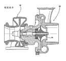
图1是现有技术涡轮增压器单元的一个截面侧视图;Figure 1 is a cross-sectional side view of a prior art turbocharger unit;
图2是根据本发明被整合到涡轮增压器中的一个排出空气冷却器的示意图;Figure 2 is a schematic diagram of an exhaust air cooler integrated into a turbocharger according to the present invention;
图3是根据本发明被整合到涡轮增压器中的排出空气冷却器的一个替代实施方案的示意图;Figure 3 is a schematic diagram of an alternative embodiment of an exhaust air cooler integrated into a turbocharger according to the invention;
图4是根据本发明将一个分离器单元结合在压缩机的上游的一个替代实施方案的示意图;Figure 4 is a schematic diagram of an alternative embodiment incorporating a separator unit upstream of the compressor according to the invention;
图5是根据本发明将一个分离器单元结合在压缩机的下游的一个替代实施方案的示意图;Figure 5 is a schematic diagram of an alternative embodiment incorporating a separator unit downstream of the compressor according to the invention;
图6是根据本发明一个分离器单元的分解视图;并且Figure 6 is an exploded view of a separator unit according to the present invention; and
图7是根据本发明带具有一个消声器的压缩机的截面侧视图。Figure 7 is a cross-sectional side view of a compressor with a muffler according to the present invention.
具体实施方式 Detailed ways
这个或这些优选实施方案的以下说明本质上仅仅是示例性的而并非旨在限制本发明、其应用或使用。The following description of the preferred embodiment(s) is merely exemplary in nature and is not intended to limit the invention, its application or uses.
图2是根据本发明的一个系统10的示意图。该系统具有一个高压EGR回路12和一个低压EGR回路14。该低压EGR回路14在一个涡轮16的下游,该涡轮是具有压缩机20的涡轮增压器单元18的一部分。该低压EGR回路14在该压缩机20的上游。通过利用一个轴22使该涡轮16与压缩机20连接。该高压EGR回路12位于该压缩机20的下游,并且位于该涡轮16的上游。Figure 2 is a schematic diagram of a
排气是由一台发动机24产生,并且经过一个排气歧管26排出。一个排气导管28被连接到该排气歧管26,该排气导管用于将排气传送给高压EGR回路12或者涡轮机16。如果排气穿过涡轮机16,这些排气将流入一个排气管30,其中排气然后将流过该低压EGR回路14或者流到该排气管30之外进入大气。Exhaust is produced by an
如果通过高压EGR回路12使排气再循环,则排气将穿过EGR阀门32、EGR冷却器34,并且然后被引入通向进气歧管38的一个进气管36。为了产生足够的EGR流通量,可以相应地调节EGR阀门32。如果该阀门32被完全打开从而要求更多流通量,进气管36还包括一个进气节流阀40,可以调节该进气节流阀以用来在该阀门32的下游产生更多的流量,由此增加高压EGR回路12进入进气管36的流量。If exhaust gas is recirculated through the high
如果来自发动机24的排气在低压EGR回路14中进行再循环,则排气穿过可变涡轮机16而进入该排气管30。柴油微粒过滤器(DPF)42被置于该排气管30中,其中排气被清除碳烟和一氧化碳以及碳氢化合物。在经过DPF 42之后,低压EGR回路14中的一个EGR阀门44被打开以便允许排气流过该低压EGR回路14进入一个压缩机-冷却器模块(总体上示为46)。If exhaust gas from the
该压缩机-冷却器模块46包含该压缩机20以及被整合到单一壳体50中的冷却器48。如图2所示,冷却器48可定位于压缩机20的上游,或在如图3所示的一个替代实施方案中,冷却器48可以定位于压缩机20的下游。还有可能具有两个冷却器48,一个在该压缩机20的上游并且一个在该压缩机的下游。在冷却器48被定位于该压缩机20的上游的应用中,一个EGR冷却器旁路阀52被用来使进入的排气绕过该冷却器48,这样排气选择性地流过一个旁路导管54并且被直接引入到该压缩机20中,而不是流过该冷却器48。新鲜空气被引入一个进气口或进气导道56、与来自该低压EGR回路14的排气混合(如果存在的话),并由压缩机20压缩、由一个次级增压空气冷却器58冷却,并且流过节流阀40。然后该气体混合物在流入进气歧管38之前与流经该高压EGR回路12的EGR混合。其他发动机布置可以包括仅一个EGR回路或多个涡轮增压器。如图3所示,该次级增压空气冷却器58位于所述压缩机20和冷却器48的下游,这样允许该增压空气冷却器58进一步降低压缩空气的温度。The compressor-
低压EGR冷却器48典型地位于低压EGR回路14的路径上。低压EGR阀门44是一个单独的阀门,它被螺栓固定在该低压EGR路径14或该冷却器48中。该低压EGR阀门44可以在定位于该冷却器48之前(即,起一个“热侧阀”的作用)或者定位于该冷却器之后(即,起一个“冷侧阀”的作用)。该EGR阀门44可以是一个提升阀类型、挡板类型的阀门或者其他类似的阀门类型。如果该冷却器48位于所述压缩机20的下游,则该排气和空气混合物将流入增压空气冷却器58中。A low pressure EGR cooler 48 is typically located in the path of the low
如图2和图3所示,一个排气节流阀60位于该排气管30内、在该低压EGR回路14的下游的某个位置,以便控制该涡轮机16的下游排气的流量和压力。还可将该低压EGR阀门44和该排气节流阀60整合到一个组合的模块(利用一个或两个致动器)中。这个模块可以位于该低压EGR回路14的接合处的排气侧上或者进气侧上。As shown in FIGS. 2 and 3 , an
图3还描述了本发明的一个替代实施方案,其中高压EGR回路12穿过模块46。EGR阀门32包含于该模块46中并控制从发动机24进入该模块46的排气的流量。在这个实施方案中,微粒过滤器42位于可变涡轮机16的上游,从而在排气经过低压或者高压EGR回路12,14进入模块46之前将排气过滤。除了该EGR阀门32位于模块46中以外,还存在一个增压空气冷却器旁路阀62,该增压空气冷却器旁路阀可以引导流经环绕压缩机-冷却器模块46的部件的EGR阀门32的排气流量。FIG. 3 also depicts an alternative embodiment of the invention in which the high
图4至图7示出本发明的其他的实施方案,其中相同的数字表示相同的元件。在图4、图6和图7中,一个总体上示为64的分离器单元被整合到压缩机-冷却器模块46中。该分离器单元64包括被连接至进气道56和低压EGR回路14的一个盖件66。该盖件66通过利用具有一个开口70的圆形凸缘68连接到进气道56上,并且通过利用一个方形的凸缘72连接到低压EGR回路14上,该方形凸缘以相对于该圆形凸缘68垂直的方式从该盖件66延伸。该盖件66的空心的,并接受一个混合器74。混合器74是一个总体上圆柱形的构件,该构件包括一连串的开口76;该混合器被一个分离器78环绕。该分离器78由金属丝网制成,该金属丝网收集并且保留来自流经该低压EGR回路14的排气中的杂物。混合器74可以形成为壳体50的一部分或者混合器74可以形成为一个分离的部件。如在此说明的混合器74和分离器78减小了气体流动的速度,这还将减小进入压缩机20的气流的压降,由此提高了压缩机20的效率。Figures 4 to 7 illustrate other embodiments of the invention, wherein like numerals indicate like elements. In FIGS. 4 , 6 and 7 , a separator unit, shown generally at 64 , is integrated into compressor-
当混合器74被置于该盖件66中时,混合器74将抵靠形成为盖件66的一部分的肩台80。这将确保任何流入盖件66的气体将被迫流过分离器78,接着流经混合器74的这些开口76。在排气穿过这些开口76之后,排气将与流入开口70的新鲜空气混合。新鲜空气与排气的混合物然后将流入压缩机20或者冷却器48,这取决于旁路阀52是否开放或者关闭。When the
该分离器单元64还包括具有多个叶片84的一个旋流器82。当空气进入分离器单元64时,这些叶片84将起作用以便在空气的流动中产生湍流,这允许空气流经混合器74时与排气更有效地混合。The
图4说明的分离器单元64被结合以便与该低压EGR回路14一起使用。然而,图4示出被结合为与EGR回路12一起使用的分离器单元64。在这个实施方案中,已经被压缩机20压缩的新鲜空气流过进气管36并流入开口70。被压缩的新鲜空气然后与来自高压EGR回路12、流入分离器单元64的排气相混合,并流入进气歧管38。该高压EGR回路12被连接到方形凸缘72上,并且将排气送入盖件66。The
图4、图5和图7示出了本发明的另一个实施方案。在这个实施方案中,一个总体上示为86的消声器被整合为压缩机-冷却器模块46的一部分。该消声器86被形成为该壳体50的一部分。这与示出一个不带有消声器86的涡轮增压器单元的图1相反。图7示出了根据这个实施方案的压缩机20的一个截面视图。该压缩机20包括一个安装于轴22上的压缩机叶轮88。一个蜗壳90环绕该压缩机叶轮88。在运行中,当压缩机叶轮88旋转时,多个鳍片92使流入该压缩机20中的空气压缩,并且迫使空气进入蜗壳90中,其中被压缩的空气然后被迫进入进气道36。消声器86包括形成于壳体50中的系列的室94。这些室94在截面上是圆形的并且环绕蜗壳90。这些室94是空心的、并且具有不同的直径以用来降低由压缩机20产生的噪声。这些不同直径的室94将各自具有不同的自然频率、并由此在压缩机叶轮88以不同的速度旋转时抵消由压缩机20产生的不同频率。Figures 4, 5 and 7 illustrate another embodiment of the present invention. In this embodiment, a muffler, shown generally at 86 , is integrated as part of the compressor-
在另一个实施方案中,这些室94都具有相同的直径,并且包含一种填充物(未示出)。该填充物是基于橡胶或有机硅的填充物,它可以吸收振动。同样可以采用其他的截面形状,例如方形、长方形、三角形、梯形或可以减小压缩机20中的噪声的其他的形状。In another embodiment, the
本发明的说明本质上仅仅是示例性的,并且因此旨在将未背离本发明的要旨的多个变体包括在本发明的范围之内。这类变体不被认为是背离开本发明的精神和范围。The description of the invention is merely exemplary in nature and, therefore, various modifications which do not depart from the gist of the invention are intended to be within the scope of the invention. Such variations are not to be regarded as a departure from the spirit and scope of the invention.
Claims (31)
Applications Claiming Priority (3)
| Application Number | Priority Date | Filing Date | Title |
|---|---|---|---|
| US84424806P | 2006-09-13 | 2006-09-13 | |
| US60/844,248 | 2006-09-13 | ||
| PCT/US2007/019847 WO2008033418A1 (en) | 2006-09-13 | 2007-09-13 | Integration of an exhaust air cooler into a turbocharger |
Publications (2)
| Publication Number | Publication Date |
|---|---|
| CN101512122A CN101512122A (en) | 2009-08-19 |
| CN101512122B true CN101512122B (en) | 2012-09-05 |
Family
ID=39184097
Family Applications (1)
| Application Number | Title | Priority Date | Filing Date |
|---|---|---|---|
| CN2007800322465A Expired - Fee Related CN101512122B (en) | 2006-09-13 | 2007-09-13 | Integration of exhaust air coolers in turbochargers |
Country Status (4)
| Country | Link |
|---|---|
| US (1) | US8122717B2 (en) |
| EP (1) | EP2076663A4 (en) |
| CN (1) | CN101512122B (en) |
| WO (1) | WO2008033418A1 (en) |
Families Citing this family (36)
| Publication number | Priority date | Publication date | Assignee | Title |
|---|---|---|---|---|
| WO2008033418A1 (en) * | 2006-09-13 | 2008-03-20 | Borgwarner Inc. | Integration of an exhaust air cooler into a turbocharger |
| DE102007024631A1 (en) * | 2007-05-24 | 2008-11-27 | Behr Gmbh & Co. Kg | Integrated charging module |
| US20090241541A1 (en) * | 2008-03-25 | 2009-10-01 | International Truck Intellectual Property Company, Llc | Pre-turbo exahust filtration system for internal combustion engines |
| EP2131022B1 (en) * | 2008-06-04 | 2011-07-13 | Iveco Motorenforschung AG | Thermal management of the after treatment system |
| WO2010045075A2 (en) * | 2008-10-16 | 2010-04-22 | Borgwarner Inc. | Module integrating mixer and particulate separator into a common housing and an engine breathing system having the module |
| WO2010072227A1 (en) * | 2008-12-22 | 2010-07-01 | Fev Motorentechnik Gmbh | Exhaust gas recirculation system and method for exhaust gas recirculation |
| DE102009027539A1 (en) * | 2009-07-08 | 2011-01-20 | Ford Global Technologies, LLC, Dearborn | Internal combustion engine with intercooler |
| GB2472228B (en) * | 2009-07-29 | 2016-01-27 | Ford Global Tech Llc | A method for reducing the fuel consumption of an engine |
| US8381518B2 (en) * | 2009-08-12 | 2013-02-26 | International Engine Intellectual Property Company, Llc | Engine exhaust system having filter before turbocharger |
| DE102009051028B4 (en) * | 2009-10-28 | 2017-12-07 | Audi Ag | Drive unit and method for operating a drive unit |
| GB2475274B (en) * | 2009-11-12 | 2016-06-15 | Gm Global Tech Operations Llc | Device and method for compressor and charge air cooler protection in an internal combustion engine |
| US8096125B2 (en) * | 2009-12-23 | 2012-01-17 | Ford Global Technologies, Llc | Methods and systems for emission system control |
| EP2546506B1 (en) * | 2010-03-09 | 2015-12-16 | Toyota Jidosha Kabushiki Kaisha | Control device for internal combustion engine |
| KR101741618B1 (en) * | 2010-06-04 | 2017-05-30 | 보르그워너 인코퍼레이티드 | Compressor of an exhaust-gas turbocharger |
| US8042527B2 (en) * | 2010-08-05 | 2011-10-25 | Ford Global Technologies, Llc | Coordination of HP and LP EGR |
| US8539767B2 (en) | 2011-03-16 | 2013-09-24 | GM Global Technology Operations LLC | Exhaust treatment system for an internal combustion engine |
| JP5585942B2 (en) * | 2011-05-27 | 2014-09-10 | 株式会社デンソー | Control device for internal combustion engine |
| DE102011078457B4 (en) * | 2011-06-30 | 2013-05-08 | Ford Global Technologies, Llc | Method for operating an internal combustion engine with intercooler |
| DE102011078454B4 (en) * | 2011-06-30 | 2013-05-08 | Ford Global Technologies, Llc | Internal combustion engine with charge air cooling |
| CN103958856B (en) * | 2011-08-15 | 2016-10-12 | 伊顿公司 | Fuel system using dual pressure high speed centrifugal pump unit |
| DE102012205027A1 (en) * | 2012-03-28 | 2013-10-02 | Mahle International Gmbh | Introducer for gases, in particular an exhaust gas recirculation device |
| US10337529B2 (en) | 2012-06-20 | 2019-07-02 | Ford Global Technologies, Llc | Turbocharger compressor noise reduction system and method |
| US9303561B2 (en) | 2012-06-20 | 2016-04-05 | Ford Global Technologies, Llc | Turbocharger compressor noise reduction system and method |
| FR2992356B1 (en) * | 2012-06-21 | 2016-04-15 | Peugeot Citroen Automobiles Sa | ENGINE GROUP WITH RECIRCULATION LINE |
| CN103912364A (en) * | 2012-12-31 | 2014-07-09 | 现代自动车株式会社 | Turbo-charger system |
| DE102013006302B4 (en) * | 2013-04-12 | 2022-07-07 | Man Energy Solutions Se | Supercharged internal combustion engine in modular design and modular systems for such internal combustion engines and charging devices |
| US8960166B2 (en) | 2013-06-03 | 2015-02-24 | Ford Global Technologies, Llc | Systems and methods for heating a pre-compressor duct to reduce condensate formation |
| KR20150111322A (en) * | 2014-03-25 | 2015-10-05 | 한온시스템 주식회사 | Device for recirculating exhaust gas of an internal combustion engine in a motor vehicle |
| DE102015104179B4 (en) | 2014-03-25 | 2022-03-03 | Hanon Systems | Devices for recirculating exhaust gas from an internal combustion engine in a motor vehicle |
| JP6183294B2 (en) * | 2014-05-30 | 2017-08-23 | トヨタ自動車株式会社 | Internal combustion engine with a supercharger |
| US9517842B2 (en) * | 2014-05-30 | 2016-12-13 | Bell Helicopter Textron Inc. | Filters for aircraft engine inlets |
| DE102014212606B4 (en) * | 2014-06-30 | 2020-12-17 | Ford Global Technologies, Llc | Motor vehicle and air filter box |
| DE102015114356A1 (en) | 2014-10-07 | 2016-04-07 | Halla Visteon Climate Control Corporation | Device of a system for guiding air of an internal combustion engine in a motor vehicle |
| DK178781B1 (en) * | 2015-06-19 | 2017-01-23 | Man Diesel & Turbo Filial Af Man Diesel & Turbo Se Tyskland | Large two-stroke turbocharged compression ignited internal combustion engine with an exhaust gas purification system |
| US11268523B2 (en) | 2017-10-10 | 2022-03-08 | Daikin Industries, Ltd. | Centrifugal compressor with recirculation structure |
| WO2022256010A1 (en) * | 2021-06-03 | 2022-12-08 | Ptp Turbo Solutions, Llc. | Systems and methods associated with a removable inlet shield |
Citations (2)
| Publication number | Priority date | Publication date | Assignee | Title |
|---|---|---|---|---|
| US5617726A (en) * | 1995-03-31 | 1997-04-08 | Cummins Engine Company, Inc. | Cooled exhaust gas recirculation system with load and ambient bypasses |
| CN1735747A (en) * | 2002-11-13 | 2006-02-15 | 霍尼韦尔国际公司 | Dual-hybrid EGR system used with turbocharged engines |
Family Cites Families (27)
| Publication number | Priority date | Publication date | Assignee | Title |
|---|---|---|---|---|
| DE2965419D1 (en) * | 1979-02-19 | 1983-07-07 | Bbc Brown Boveri & Cie | Exhaust-gas driven turbocharger having two stages |
| US4835963A (en) * | 1986-08-28 | 1989-06-06 | Allied-Signal Inc. | Diesel engine particulate trap regeneration system |
| JPH08170539A (en) * | 1994-12-16 | 1996-07-02 | Mitsubishi Motors Corp | Supercharged internal combustion engine with exhaust gas recirculation controller |
| AT408785B (en) * | 1995-11-30 | 2002-03-25 | Blank Otto Ing | CHARGER FOR THE CHARGE AIR OF AN INTERNAL COMBUSTION ENGINE |
| JP3134751B2 (en) | 1995-12-20 | 2001-02-13 | 国産電機株式会社 | Capacitor discharge type ignition device for internal combustion engine |
| US5791144A (en) * | 1997-05-09 | 1998-08-11 | Alliedsignal Inc. | Turbocharger pressure compensation system |
| US5771868A (en) | 1997-07-03 | 1998-06-30 | Turbodyne Systems, Inc. | Turbocharging systems for internal combustion engines |
| GB0018406D0 (en) * | 2000-07-28 | 2000-09-13 | Serck Heat Transfer Limited | EGR bypass tube cooler |
| JP4295904B2 (en) * | 2000-10-05 | 2009-07-15 | 株式会社小松製作所 | Multi-cylinder engine air supply structure |
| US6367256B1 (en) * | 2001-03-26 | 2002-04-09 | Detroit Diesel Corporation | Exhaust gas recirculation with condensation control |
| DE10203003B4 (en) * | 2002-01-26 | 2007-03-15 | Behr Gmbh & Co. Kg | Exhaust gas heat exchanger |
| US7278472B2 (en) * | 2002-09-20 | 2007-10-09 | Modine Manufacturing Company | Internally mounted radial flow intercooler for a combustion air changer |
| GB2393759B (en) * | 2002-10-04 | 2004-12-15 | Visteon Global Tech Inc | Air intake cooling system and method |
| US6805108B2 (en) * | 2002-12-20 | 2004-10-19 | Caterpillar Inc | Heat exchanger for a supercharger |
| US6868840B2 (en) * | 2003-06-05 | 2005-03-22 | Detroit Diesel Corporation | Charged air intake system for an internal combustion engine |
| US6981375B2 (en) | 2003-09-16 | 2006-01-03 | Detroit Diesel Corporation | Turbocharged internal combustion engine with EGR flow |
| DE10348136A1 (en) * | 2003-10-16 | 2005-05-12 | Daimler Chrysler Ag | Internal combustion engine with charge |
| DE102004019554C5 (en) | 2004-04-22 | 2014-03-27 | Pierburg Gmbh | Exhaust gas recirculation system for an internal combustion engine |
| JP4389739B2 (en) * | 2004-09-29 | 2009-12-24 | 三菱自動車工業株式会社 | Internal combustion engine with a supercharger |
| US7299122B2 (en) * | 2004-11-15 | 2007-11-20 | Perkins Michael T | On demand boost conditioner (ODBC) |
| US7195006B2 (en) * | 2004-11-29 | 2007-03-27 | Southwest Research Institute | Exhaust gas recirculation system with control of EGR gas temperature |
| US8171731B2 (en) | 2005-05-11 | 2012-05-08 | Borgwarner Inc. | Engine air management system |
| JP2007023911A (en) * | 2005-07-19 | 2007-02-01 | Denso Corp | Exhaust gas recirculation device |
| WO2007025204A2 (en) * | 2005-08-26 | 2007-03-01 | Saleen Incorporated | Apparatus and method for boosting engine performance |
| DE102006005106A1 (en) * | 2006-02-04 | 2007-08-09 | Modine Manufacturing Co., Racine | Heat exchanger with a connection plate, in particular intercooler |
| WO2008033418A1 (en) * | 2006-09-13 | 2008-03-20 | Borgwarner Inc. | Integration of an exhaust air cooler into a turbocharger |
| US8701635B2 (en) * | 2008-11-03 | 2014-04-22 | Robert Simons | Supercharger system for motorized vehicles and related transportation |
-
2007
- 2007-09-13 WO PCT/US2007/019847 patent/WO2008033418A1/en not_active Ceased
- 2007-09-13 CN CN2007800322465A patent/CN101512122B/en not_active Expired - Fee Related
- 2007-09-13 EP EP07838112A patent/EP2076663A4/en not_active Withdrawn
- 2007-09-13 US US12/440,480 patent/US8122717B2/en not_active Expired - Fee Related
Patent Citations (2)
| Publication number | Priority date | Publication date | Assignee | Title |
|---|---|---|---|---|
| US5617726A (en) * | 1995-03-31 | 1997-04-08 | Cummins Engine Company, Inc. | Cooled exhaust gas recirculation system with load and ambient bypasses |
| CN1735747A (en) * | 2002-11-13 | 2006-02-15 | 霍尼韦尔国际公司 | Dual-hybrid EGR system used with turbocharged engines |
Non-Patent Citations (1)
| Title |
|---|
| JP特开平8-170539A 1996.07.02 |
Also Published As
| Publication number | Publication date |
|---|---|
| EP2076663A1 (en) | 2009-07-08 |
| CN101512122A (en) | 2009-08-19 |
| EP2076663A4 (en) | 2010-11-24 |
| US8122717B2 (en) | 2012-02-28 |
| WO2008033418A1 (en) | 2008-03-20 |
| US20100043761A1 (en) | 2010-02-25 |
Similar Documents
| Publication | Publication Date | Title |
|---|---|---|
| CN101512122B (en) | Integration of exhaust air coolers in turbochargers | |
| JP4906847B2 (en) | Engine air management device | |
| EP2342446B1 (en) | Module integrating mixer and particulate separator into a common housing and an engine breathing system having the module | |
| US7343742B2 (en) | Exhaust turbocharger | |
| US9157396B2 (en) | Nozzled turbine | |
| US20070039320A1 (en) | Surge control system for a compressor | |
| KR20080095843A (en) | Mixing unit for low pressure EBR condensate entering the compressor | |
| CN101578439B (en) | Turbocharger | |
| CN101960132A (en) | Motor vehicle internal combustion engine egr loop | |
| JP2011220127A (en) | Exhaust gas circulation device | |
| CN101479447A (en) | Enhanced engine air breathing system with after treatment device before the turbocharger | |
| CN102817646A (en) | Turbine housing and method for directing exhaust | |
| JP6057834B2 (en) | Combustion engine | |
| EP3438429B1 (en) | Engine with turbo supercharger | |
| US20070261399A1 (en) | Cooling device | |
| JP2013238144A (en) | Low-pressure loop egr device | |
| CN102562367B (en) | For the EGR valve device of internal-combustion engine | |
| CN101321944A (en) | Exhaust gas recirculation mixer for turbocharged internal combustion engines | |
| US7654078B2 (en) | Exhaust gas particle collector | |
| WO2009076342A2 (en) | Module integrating various combinations of an exhaust air cooler, valve, throttle valve, mixer and particle separator into a common housing | |
| EP2825761B1 (en) | Turbo pump | |
| JP2007127070A (en) | Supercharged internal combustion engine | |
| KR20230074925A (en) | Engine system | |
| JP2017180386A (en) | Engine with turbo supercharger |
Legal Events
| Date | Code | Title | Description |
|---|---|---|---|
| C06 | Publication | ||
| PB01 | Publication | ||
| C10 | Entry into substantive examination | ||
| SE01 | Entry into force of request for substantive examination | ||
| C14 | Grant of patent or utility model | ||
| GR01 | Patent grant | ||
| CF01 | Termination of patent right due to non-payment of annual fee | ||
| CF01 | Termination of patent right due to non-payment of annual fee |
Granted publication date: 20120905 |