CN101466500B - Abrasive articles and methods of making and using same - Google Patents
Abrasive articles and methods of making and using same Download PDFInfo
- Publication number
- CN101466500B CN101466500B CN2007800219515A CN200780021951A CN101466500B CN 101466500 B CN101466500 B CN 101466500B CN 2007800219515 A CN2007800219515 A CN 2007800219515A CN 200780021951 A CN200780021951 A CN 200780021951A CN 101466500 B CN101466500 B CN 101466500B
- Authority
- CN
- China
- Prior art keywords
- filter medium
- abrasive
- filter
- attachment interface
- interface member
- Prior art date
- Legal status (The legal status is an assumption and is not a legal conclusion. Google has not performed a legal analysis and makes no representation as to the accuracy of the status listed.)
- Expired - Fee Related
Links
Images


Classifications
-
- B—PERFORMING OPERATIONS; TRANSPORTING
- B24—GRINDING; POLISHING
- B24D—TOOLS FOR GRINDING, BUFFING OR SHARPENING
- B24D11/00—Constructional features of flexible abrasive materials; Special features in the manufacture of such materials
- B24D11/02—Backings, e.g. foils, webs, mesh fabrics
-
- B—PERFORMING OPERATIONS; TRANSPORTING
- B24—GRINDING; POLISHING
- B24B—MACHINES, DEVICES, OR PROCESSES FOR GRINDING OR POLISHING; DRESSING OR CONDITIONING OF ABRADING SURFACES; FEEDING OF GRINDING, POLISHING, OR LAPPING AGENTS
- B24B23/00—Portable grinding machines, e.g. hand-guided; Accessories therefor
- B24B23/005—Auxiliary devices used in connection with portable grinding machines, e.g. holders
Landscapes
- Engineering & Computer Science (AREA)
- Mechanical Engineering (AREA)
- Polishing Bodies And Polishing Tools (AREA)
- Finish Polishing, Edge Sharpening, And Grinding By Specific Grinding Devices (AREA)
- Filtering Materials (AREA)
Abstract
本发明描述了一种通过超声波焊接工艺形成的磨料制品,该磨料制品具有多孔的涂覆磨料构件、过滤介质和附连界面构件。所述磨料制品可以用于研磨工件。
This invention describes an abrasive article formed by an ultrasonic welding process, the abrasive article having a porous coated abrasive component, a filter medium, and an attachment interface component. The abrasive article can be used for grinding workpieces.
Description
背景技术Background technique
磨料制品用在进行研磨、磨削和抛光应用的行业中。磨料制品可以有多种尺寸和形状,如带状、盘状及片状等。Abrasive articles are used in industries where grinding, grinding and polishing applications are performed. Abrasive articles can come in a variety of sizes and shapes, such as ribbons, discs, and flakes.
通常,在采用“片状制品”(即,盘状和片状)形式的磨料制品时,使用支撑垫将磨料制品装配或连接到研磨工具上。一种支撑垫具有多个集尘孔,这些集尘孔通过一系列凹槽相连。集尘孔通常与真空源相连,以帮助控制切屑在磨料制品的研磨表面上的积聚。已知的是,去除研磨表面上的切屑、尘屑和碎屑会提高磨料制品的性能。Typically, when abrasive articles are employed in the form of "sheet articles" (ie, disks and sheets), back-up pads are used to mount or attach the abrasive article to the abrasive tool. A support pad has a plurality of dust collection holes connected by a series of grooves. The dust collection holes are often connected to a vacuum source to help control the accumulation of swarf on the abrasive surface of the abrasive article. It is known that the removal of swarf, dust and debris from abrasive surfaces improves the performance of abrasive articles.
一些研磨工具具有带集尘装置的一体式真空系统。这些研磨工具的吸出能力和保持能力有限,这部分是由于现有磨盘及其相关的支撑垫所需要的抽吸要求所造成的。Some grinding tools have an integrated vacuum system with dust collection. The limited suction and retention capabilities of these abrasive tools are due in part to the suction requirements required by existing abrasive discs and their associated back-up pads.
在一些研磨工具的构造中,通过与研磨工具相连的软管将切屑收集在复杂的集尘系统中。然而,研磨工具操作人员手头并非总有集尘系统可用。此外,集尘系统需要使用软管,而这些软管可能会很笨重,并且可能影响到操作人员对研磨工具的操作。In some constructions of grinding tools, the chips are collected in complex dust collection systems via hoses connected to the grinding tool. However, abrasive tool operators do not always have a dust collection system at hand. Additionally, dust collection systems require the use of hoses, which can be cumbersome and can interfere with the operator's ability to access the abrasive tool.
因此,一直需要一种提供具有吸尘能力的研磨系统的替代方式。Accordingly, there remains a need for an alternative way of providing grinding systems with dust suction capabilities.
发明内容Contents of the invention
在一个方面,本发明提供一种磨料制品,该磨料制品包括:In one aspect, the invention provides an abrasive article comprising:
多孔的涂覆磨料构件,该多孔的涂覆磨料构件包含磨粒,所述磨粒通过底胶层和复胶层固定到柔性的不可压缩的薄背衬的第一主表面上;和a porous coated abrasive member comprising abrasive particles secured by a make layer and a size layer to the first major surface of the flexible, incompressible thin backing; and
粘合剂层,其粘附到背衬的与第一主表面相对的第二主表面上,其中孔延伸穿过磨料层、背衬、以及粘合剂层;an adhesive layer adhered to a second major surface of the backing opposite the first major surface, wherein the holes extend through the abrasive layer, the backing, and the adhesive layer;
第一过滤介质,其具有第一表面和与第一表面相对的第二表面,第一过滤介质的第一表面粘附到多孔的涂覆磨料构件的粘合剂层上,第一过滤介质限定由通道侧壁形成的分立通道,该分立通道从第一过滤介质的第一表面延伸到第一过滤介质的第二表面;A first filter medium having a first surface and a second surface opposite the first surface, the first surface of the first filter medium adhered to the adhesive layer of the porous coated abrasive member, the first filter medium defining discrete channels formed by channel sidewalls extending from the first surface of the first filter medium to the second surface of the first filter medium;
第二过滤介质,其具有第一表面和与之相对的第二表面,其中第二过滤介质的第一表面与第一过滤介质的第二表面在界面处紧邻;和a second filter medium having a first surface and an opposite second surface, wherein the first surface of the second filter medium is immediately adjacent at the interface with the second surface of the first filter medium; and
附连界面构件,其固定到第二过滤介质的第二表面上,其中附连界面构件包含织物,并具有紧邻第二过滤介质的后表面和与后表面相对的向外设置的可接合表面;an attachment interface member secured to a second surface of the second filter medium, wherein the attachment interface member comprises a fabric and has a rear surface proximate to the second filter media and an outwardly disposed engageable surface opposite the rear surface;
其中至少一部分的孔与至少一部分的分立通道相配合,以允许颗粒从多孔的涂覆磨料构件流向第二过滤介质,其中第一过滤介质、第二过滤介质、以及附连界面构件通过位于界面处的至少一个焊接区(weld)连接在一起。wherein at least a portion of the pores cooperate with at least a portion of the discrete channels to allow particles to flow from the porous coated abrasive member to the second filter medium, wherein the first filter medium, the second filter medium, and the attached interface member pass through at the interface At least one welding area (weld) of the connected together.
根据本发明的磨料制品可用于(例如)研磨工件的表面。因此,在另一方面,本发明提供了一种研磨表面的方法,包括使表面与根据本发明的磨料制品摩擦接触,并使磨料制品与表面相对移动,以研磨表面。Abrasive articles according to the invention can be used, for example, to abrade the surface of a workpiece. Accordingly, in another aspect, the invention provides a method of abrading a surface comprising frictionally contacting the surface with an abrasive article according to the invention and moving the abrasive article relative to the surface to abrade the surface.
相对于使焊接区与涂覆磨料构件紧邻的对应的磨料制品而言,根据本发明的磨料制品一般显示出至少一种改进的研磨特性。Abrasive articles according to the present invention generally exhibit at least one improved abrasive characteristic relative to corresponding abrasive articles having a weld zone in close proximity to a coated abrasive member.
在另一方面,本发明提供一种制备磨料制品的方法,该方法包括:提供多孔的涂覆磨料构件,该多孔的涂覆磨料构件包含:磨粒,所述磨粒通过底胶层和复胶层固定到柔性的不可压缩的薄背衬的第一主表面上;和In another aspect, the present invention provides a method of making an abrasive article, the method comprising: providing a porous coated abrasive member, the porous coated abrasive member comprising: abrasive particles, the abrasive particles through the make layer and the overcoat a bondline secured to the first major surface of the flexible, incompressible, thin backing; and
粘合剂层,其粘附到背衬的与第一主表面相对的第二主表面上,其中孔延伸穿过磨料层、背衬、和粘合剂层;an adhesive layer adhered to a second major surface of the backing opposite the first major surface, wherein the holes extend through the abrasive layer, the backing, and the adhesive layer;
提供第一过滤介质,其具有第一表面和与第一表面相对的第二表面,第一过滤介质限定由通道侧壁形成的分立通道,该分立通道从第一过滤介质的第一表面延伸到第一过滤介质的第二表面;A first filter medium is provided having a first surface and a second surface opposite the first surface, the first filter medium defining discrete channels formed by channel sidewalls extending from the first surface of the first filter medium to a second surface of the first filter medium;
提供第二过滤介质,其具有第一表面和与之相对的第二表面;providing a second filter medium having a first surface and an opposite second surface;
提供附连界面构件,其包含织物,并具有后表面和与后表面相对的可接合表面;providing an attachment interface member comprising a fabric and having a rear surface and an engageable surface opposite the rear surface;
使第二过滤介质的第一表面与第一过滤介质的第二表面接触;contacting the first surface of the second filter medium with the second surface of the first filter medium;
使附连界面构件的后表面与第二过滤介质的第二表面接触;contacting the rear surface of the attachment interface member with the second surface of the second filter media;
形成至少一个焊接区以连接第一过滤介质、第二过滤介质、以及附连界面构件,其中该焊接区位于第一介质的第二表面处;并且forming at least one weld to connect the first filter medium, the second filter medium, and the attachment interface member, wherein the weld is located at the second surface of the first medium; and
将多孔的涂覆磨料构件的粘合剂层粘附到第一过滤介质的第一表面上,adhering the adhesive layer of the porous coated abrasive member to the first surface of the first filter medium,
其中至少一部分的孔与至少一部分的分立通道相配合,以允许颗粒从多孔的涂覆磨料构件流向第二过滤介质。At least a portion of the pores cooperate with at least a portion of the discrete channels to allow particles to flow from the porous coated abrasive member to the second filter medium.
在一些实施例中,所述的至少一个焊接区由以下方法形成,所述方法包括:In some embodiments, the at least one pad is formed by a method comprising:
使第一过滤介质的第一表面与超声波焊接头或砧中的一者接触,使附连界面构件的可接合表面与超声波焊接头或砧中的另一者接触,并且超声形成至少一个焊接区以连接第一过滤介质、第二过滤介质、以及附连界面构件。contacting the first surface of the first filter medium with one of the sonotrode or the anvil, contacting the engageable surface of the attachment interface member with the other of the sonotrode or the anvil, and ultrasonically forming at least one weld to connect the first filter medium, the second filter medium, and the attachment interface member.
在一些实施例中,该方法还包括在连接第一过滤介质、第二过滤介质、以及附连界面构件之前将第一过滤介质粘结到第二过滤介质上。In some embodiments, the method further includes bonding the first filter medium to the second filter medium prior to connecting the first filter medium, the second filter medium, and attaching the interface member.
在一些实施例中,第一过滤介质、第二过滤介质、以及附连界面构件通过焊接区连接在一起,该焊接区包括由相交线段形成的连续网状结构。在一些实施例中,第一过滤介质、第二过滤介质、以及附连界面构件通过至少20个焊接区连接在一起。在一些实施例中,焊接区具有从1至10毫米范围内的最大宽度。在一些实施例中,第一过滤介质具有1至20毫米范围内的最大厚度。在一些实施例中,通道侧壁包含聚合物薄膜,该聚合物薄膜可以包括结构化表面,并且可以带有静电荷。在一些实施例中,分立通道具有至少0.1毫米的平均有效圆直径。在一些实施例中,第二过滤介质包含非织造过滤材料,该非织造过滤材料可以包含聚烯烃纤维并且具有在10至200克/平方米范围内的基重。在一些实施例中,多孔的涂覆磨料构件、第一过滤介质、第二过滤介质以及附连界面构件中的至少两者是共延伸的。在一些实施例中,附连界面构件包含压敏粘合剂。在一些实施例中,附连界面构件的织物包含聚丙烯。在一些实施例中,附连界面构件具有两部分机械接合系统的套环部分或者钩部分。在一些实施例中,磨料制品包括磨盘。In some embodiments, the first filter medium, the second filter medium, and the attachment interface member are joined together by a weld zone comprising a continuous network of intersecting line segments. In some embodiments, the first filter medium, the second filter medium, and the attachment interface member are joined together by at least 20 welds. In some embodiments, the weld zone has a maximum width ranging from 1 to 10 millimeters. In some embodiments, the first filter medium has a maximum thickness in the range of 1 to 20 millimeters. In some embodiments, the channel sidewalls comprise a polymer film, which can include a structured surface, and which can be electrostatically charged. In some embodiments, the discrete channels have an average effective circular diameter of at least 0.1 mm. In some embodiments, the second filter medium comprises a nonwoven filter material, which may comprise polyolefin fibers and have a basis weight in the range of 10 to 200 grams per square meter. In some embodiments, at least two of the porous coated abrasive member, the first filter medium, the second filter medium, and the attachment interface member are coextensive. In some embodiments, the attachment interface member comprises a pressure sensitive adhesive. In some embodiments, the fabric to which the interface member is attached comprises polypropylene. In some embodiments, the attachment interface member has either a loop portion or a hook portion of a two-part mechanical engagement system. In some embodiments, the abrasive article includes an abrasive disc.
如本文所用,As used herein,
术语“织物”包括布和网状制品,其可以是织造的、非织造的、针织的或粘结的;The term "fabric" includes cloth and mesh articles, which may be woven, nonwoven, knitted or bonded;
“柔性的”是指能够挠曲,而不会永久经受物理损坏;"flexible" means capable of flexing without permanently sustaining physical damage;
“不可压缩的”是指强的抗压缩性;"Incompressible" means strong resistance to compression;
“薄”是指从一个表面到相对的表面的量值相对较小;并且"thin" means a relatively small amount from one surface to the opposite surface; and
“工件”是指待研磨的物体,例如木材、金属、清水墙或涂漆表面。"Workpiece" means the object to be ground, such as wood, metal, drywall or painted surfaces.
附图说明Description of drawings
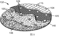
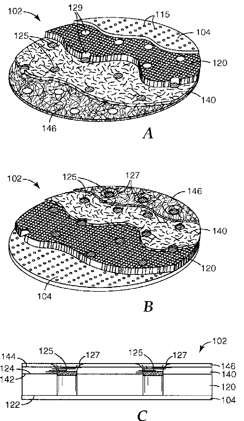
图1A是示例性磨料制品的透视图,此示例性磨料制品被部分切除以显露形成磨料制品的组件;Figure 1A is a perspective view of an exemplary abrasive article partially cut away to reveal components forming the abrasive article;
图1B是图1A中示出的示例性磨料制品的透视图,此示例性磨料制品的取向被倒置并且被部分切除以显露形成磨料制品的组件;FIG. 1B is a perspective view of the exemplary abrasive article shown in FIG. 1A , with the orientation of the exemplary abrasive article inverted and partially cut away to reveal components forming the abrasive article;
图1C是图1B中示出的示例性磨料制品的示意性剖视图;Figure 1C is a schematic cross-sectional view of the exemplary abrasive article shown in Figure 1B;
图2是示例性磨料制品的透视示意图,此示例性磨料制品被部分切除以显露形成磨料制品的组件;Figure 2 is a schematic perspective view of an exemplary abrasive article partially cut away to reveal components forming the abrasive article;
图3A是包括堆叠的薄膜层的示例性第一过滤介质的透视图;3A is a perspective view of an exemplary first filter medium comprising stacked film layers;
图3B是图3A所示的第一过滤介质的一部分的俯视图;Figure 3B is a top view of a portion of the first filter medium shown in Figure 3A;
图4是包括打孔主体的示例性第一过滤介质的透视图;Figure 4 is a perspective view of an exemplary first filter media comprising a perforated body;
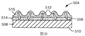
图5A是示例性的多孔涂覆磨料构件的俯视图;并且Figure 5A is a top view of an exemplary porous coated abrasive member; and
图5B是图5A示出的多孔涂覆磨料构件的截面的剖视图。5B is a cross-sectional view of a section of the porous coated abrasive member shown in FIG. 5A.
具体实施方式Detailed ways
图1A为被部分切除的示例性磨料制品102的透视图。如图1A所示,磨料制品102具有多孔的涂覆磨料构件104、第一过滤介质120、第二过滤介质140、以及附连界面构件146。第一过滤介质120、第二过滤介质140、以及附连界面构件146通过焊接区125连接在一起。如在这个视图中所示,在用于将第一过滤介质120、第二过滤介质140、以及附连界面构件146结合的超声波焊接工艺中,紧邻焊接区125的腔129形成于第一过滤介质120中。多孔的涂敷磨料构件104具有孔115,所述孔在研磨过程中允许碎屑通过多孔的涂覆磨料构件104流动。然后由磨料制品中的过滤介质来捕获颗粒。FIG. 1A is a perspective view of an exemplary
图1B示出了已被部分切除以显露磨料制品的组件的磨料制品102的倒置透视图。如本视图所示,在用于将第一过滤介质120、第二过滤介质140、以及附连界面构件146结合的超声波焊接工艺中,紧邻焊接区125的褶皱127形成于第二过滤介质140和附连界面构件146中。Figure IB shows an inverted perspective view of
图1C示出磨料制品102(图1B所示)的示意性剖视图。如图1C所示,磨料制品102包括多个层。第一过滤介质120具有第一表面122和与第一表面122相对的第二表面124。第二过滤介质140具有第一表面142和与第一表面142相对的第二表面144。第一过滤介质120的第一表面122紧邻多孔的涂覆磨料构件104。第一过滤介质120的第二表面124紧邻第二过滤介质140的第一表面142。附连界面构件146固定到第二过滤介质140的第二表面144上。焊接区125位于第一介质120的第二表面124处并且形成褶皱127的末端。Figure 1C shows a schematic cross-sectional view of abrasive article 102 (shown in Figure IB). As shown in Figure 1C,
图2示出另一个示例性磨料制品202。第一过滤介质220包括第一表面222和与第一表面222相对的第二表面224。第二过滤介质240包括第一表面242和与第一表面242相对的第二表面244。第一过滤介质220的第一表面222紧邻多孔的涂覆磨料构件204。第一过滤介质220的第二表面224紧邻第二过滤介质240的第一表面242。附连界面构件246固定到第二过滤介质240的第二表面244上。磨料制品202不同于磨料制品102(图1A和2A中所示)之处在于,(例如)单个焊接区226包括沿着第二表面244设置的由相交线段形成的连续网状结构225。焊接区226位于第一介质220的第二表面224处并且形成褶皱227的末端。Another exemplary
通常,不管是多个分立的焊接区还是包括由相交的焊接线或线段形成的连续网状结构的单个焊接区都可以是直的或弯曲的,并且应当在第一过滤介质的整个第二表面上大体上均匀地分布,以在整个磨料制品中提供相对均匀的结构特性和性能特性。这可以通过多个点焊或者为线状和/或线段(即相对短的焊接线)状的焊接区来实现,或通过由相交的线和/或线段形成的焊接连续网状结构(例如,蜂窝式图案或筛网图案)来实现。因此,焊接区的密度为在每30平方英寸的第一过滤介质的第二表面上具有至少一个焊接区,并可以是(例如)至少5、10、15、20、25、30、40、50个或以上的焊接区,通常选择的实际数目使得满足适当的性能指标(例如,结构完整性或粉尘容量)。当然,较大的磨料制品通常比较小的磨料制品具有更多的焊接区。In general, either a plurality of discrete welds or a single weld comprising a continuous network of intersecting weld lines or line segments may be straight or curved and should be formed over the entire second surface of the first filter media substantially evenly distributed throughout the abrasive article to provide relatively uniform structural and performance properties. This can be accomplished by multiple spot welds or weld zones in the form of lines and/or line segments (i.e., relatively short weld lines), or by a continuous network of welds formed by intersecting lines and/or line segments (e.g., honeycomb pattern or screen pattern) to achieve. Accordingly, the density of welded areas is such that there is at least one welded area per 30 square inches of the second surface of the first filter media, and can be, for example, at least 5, 10, 15, 20, 25, 30, 40, 50 One or more weld zones, usually a practical number chosen such that appropriate performance criteria (eg, structural integrity or dust holding capacity) are met. Of course, larger abrasive articles generally have more weld zones than smaller abrasive articles.
附连界面构件包含织物,并且可以包括两部分机械接合系统的(例如)套环部分或者钩部分。在一些实施例中,附连界面构件可以包含其上具有压敏粘合剂层织物,所述的粘合剂层具有可任选的隔离衬片以搬运时对其进行保护。通常,附连界面构件是多孔的并且允许空气通过,然而这不是必要条件。The attachment interface member comprises a fabric and may include, for example, a loop portion or a hook portion of a two-part mechanical engagement system. In some embodiments, the attachment interface member may comprise a fabric having thereon a layer of pressure sensitive adhesive with an optional release liner to protect it during handling. Typically, the attachment interface member is porous and allows air to pass through, however this is not a requirement.
附连界面构件可以包括非织造的、织造的或针织的套环织物,其可以用于将磨料制品固定于具有互补配套组件的支撑垫上。The attachment interface member may comprise a nonwoven, woven or knitted loop fabric, which may be used to secure the abrasive article to a back-up pad with complementary mating components.
织造和针织的套环织物可以具有包含在其织物结构内的套环形成细丝或纱线,以形成与钩接合的直立的套环。非织造的套环织物可以具有由互锁纤维形成的套环。在一些非织造套环附连界面织物中,套环是通过使纱线穿过非织造纤维网进行缝合而形成,从而形成直立的套环。Woven and knitted loop fabrics may have loop-forming filaments or yarns incorporated within their fabric structure to form upstanding loops that engage hooks. Nonwoven loop fabrics may have loops formed from interlocking fibers. In some nonwoven loop attachment interface fabrics, the loops are formed by stitching yarns through the nonwoven web to form standing loops.
适合于用作套环织物的可用的非织造物包括(例如):气流成网织物、纺粘织物、水刺织物、熔喷织物以及粘合梳理纤维网。可通过本领域的技术人员所知的各种方法(包括(例如)针刺法、缝编法、水刺法、化学粘接法和热粘接法)来粘合非织造织物。所用的织造或非织造织物可由天然纤维(例如木纤维或棉纤维)、合成纤维(例如聚酯纤维或聚丙烯纤维)或天然纤维与合成纤维的组合制成。在一些实施例中,附连界面构件由尼龙、聚酯、聚丙烯或其组合制成。Useful nonwovens suitable for use as loop fabrics include, for example, airlaid fabrics, spunbond fabrics, spunlace fabrics, meltblown fabrics, and bonded carded webs. Nonwovens can be bonded by various methods known to those skilled in the art including, for example, needle punching, stitchbonding, hydroentanglement, chemical bonding, and thermal bonding. The woven or nonwoven fabrics used may be made of natural fibers such as wood fibers or cotton fibers, synthetic fibers such as polyester fibers or polypropylene fibers, or a combination of natural and synthetic fibers. In some embodiments, the attachment interface member is made of nylon, polyester, polypropylene, or combinations thereof.
套环织物可以具有开放式结构,其不会显著妨碍气流从其通过。The loop fabric may have an open structure that does not significantly impede airflow therethrough.
附连界面构件可以包括钩状物,其可以用本领域的技术人员已知的许多不同的方法之一而制得。一些合适的钩状物及其制备工艺包括(例如)在美国专利No.5,058,247(Thomas等人)和No.6,579,161(Chesley等人)、以及美国专利申请公开No.2004/0170801 A1(Seth等人)中所描述的那些。The attachment interface member may include hooks, which may be made by one of many different methods known to those skilled in the art. Some suitable hooks and their preparation are described, for example, in U.S. Patent Nos. 5,058,247 (Thomas et al.) and No. 6,579,161 (Chesley et al.), and in U.S. Patent Application Publication No. 2004/0170801 A1 (Seth et al. ) described in those.
第二过滤介质可以包括在过滤产品(尤其是空气过滤产品)中经常使用的各种开孔过滤介质。例如,第二过滤介质可以是纤维材料、泡沫、开孔薄膜等。在一些实施例中,第二过滤介质包括纤维材料,例如,纤维过滤网(例如非织造纤维网),但是也可以使用织造纤维网和针织纤维网。The second filter media may include various open cell filter media commonly used in filtration products, especially air filtration products. For example, the second filter medium may be a fibrous material, foam, open cell film, or the like. In some embodiments, the second filter medium comprises a fibrous material, eg, a fibrous filter web (eg, a nonwoven web), although woven and knitted webs may also be used.
在一些实施例中,第二过滤介质包括纤维材料,所述纤维材料具有的纤维直径小于100微米,有时小于50微米,有时小于1微米。在第二过滤介质中可以使用纤维材料的多种基重。第二过滤介质的基重通常在5克/平方米至1000克/平方米的范围内。在一些实施例中,第二过滤介质的基重在10克/平方米至200克/平方米的范围内。如果需要,第二过滤介质可以包括一个或多个过滤介质层(网)。In some embodiments, the second filter medium comprises a fibrous material having a fiber diameter of less than 100 microns, sometimes less than 50 microns, sometimes less than 1 micron. Various basis weights of fibrous materials can be used in the second filter media. The basis weight of the second filter media typically ranges from 5 grams per square meter to 1000 grams per square meter. In some embodiments, the second filter media has a basis weight in the range of 10 grams/square meter to 200 grams/square meter. If desired, the second filter media may comprise one or more layers (mesh) of filter media.
第二过滤介质可以由多种有机聚合物材料(包括混合物和共混物)制成。合适的有机聚合物材料的实例包括多种市售材料,例如:聚烯烃,例如,聚丙烯、线性低密度聚乙烯、聚-1-丁烯、聚(4-甲基-1-戊烯)、聚四氟乙烯、聚三氟氯乙烯、或聚氯乙烯;芳族聚芳烃,例如,聚苯乙烯;聚碳酸酯;聚酯,例如,聚对苯二甲酸乙二醇酯或聚乳酸(PLA);以及它们的组合(包括共混物或共聚物)。可用的聚烯烃可以不含支链烷基。其它合适的材料包括:非热塑性纤维,例如纤维素纤维、人造丝、丙烯酸纤维以及改性的丙烯酸纤维(卤素改性的丙烯酸纤维);聚酰胺或聚酰亚胺纤维,例如以商品名“NOMEX”和“KEVLAR”从杜邦公司(E.I.du Pont deNemours and Co.)获得的那些;以及它们的组合。The second filter media can be made from a variety of organic polymeric materials including mixtures and blends. Examples of suitable organic polymeric materials include various commercially available materials such as: polyolefins, e.g., polypropylene, linear low density polyethylene, poly-1-butene, poly(4-methyl-1-pentene) , polytetrafluoroethylene, polychlorotrifluoroethylene, or polyvinyl chloride; aromatic polyaromatics, such as polystyrene; polycarbonate; polyesters, such as polyethylene terephthalate or polylactic acid ( PLA); and combinations thereof (including blends or copolymers). Useful polyolefins may be free of branched chain alkyl groups. Other suitable materials include: non-thermoplastic fibers such as cellulosic fibers, rayon, acrylic fibers and modified acrylic fibers (halogen-modified acrylic fibers); polyamide or polyimide fibers such as those sold under the trade name "NOMEX ” and “KEVLAR” those obtained from E.I. du Pont de Nemours and Co.; and combinations thereof.
在采用了非织造材料作为第二过滤介质的实施例中,可以采用传统非织造技术(包括熔喷法、纺粘法、梳理法、气流成网法(干法成网)、湿法成网等)将非织造过滤介质形成为纤维网。如果需要,可以采用已知方法(包括,例如使用电晕放电电极或高强度电场)使纤维或纤维网带电。可以在形成纤维期间、将纤维形成过滤纤维网之前、或形成过程中、或者形成过滤纤维网之后,使纤维带电。形成第二过滤介质的纤维甚至还可以在与第一过滤介质连接之后再带电。第二过滤介质可以包括涂覆有聚合物粘结剂或粘合剂(包括压敏粘合剂)的纤维。In embodiments where a nonwoven material is used as the second filter medium, conventional nonwoven techniques (including meltblown, spunbond, carded, airlaid (drylaid), wetlaid) may be used. etc.) to form the nonwoven filter media into a fiber web. If desired, the fibers or webs can be charged using known methods including, for example, the use of corona discharge electrodes or high intensity electric fields. The fibers may be charged during fiber formation, before forming the fibers into a filter web, or during formation, or after forming a filter web. The fibers forming the second filter medium can even be recharged after connection with the first filter medium. The second filter media can include fibers coated with a polymeric binder or adhesive, including pressure sensitive adhesives.
图3A示出了包括堆叠薄膜层的示例性第一过滤介质320的透视图。图3B示出了图3A所示的第一过滤介质320的部分俯视图。如图3A所示,第一过滤介质320具有可以变化以适应不同应用的厚度H。例如,如果特定研磨应用需要具有颗粒保持能力较大的磨料制品,则可以增大第一过滤介质的厚度。可以通过其它参数(包括,例如,磨料制品的所需刚性)来限定第一过滤介质的厚度。在一些实施例中,与磨料制品中使用的其它过滤介质相比,根据本发明的磨料制品的第一过滤介质刚性相对较大。FIG. 3A shows a perspective view of an exemplary
通常第一过滤介质具有至少0.5毫米的平均厚度。在一些实施例中,第一过滤介质具有至少1毫米的平均厚度。在其它实施例中,第一过滤介质具有至少3毫米的平均厚度。Typically the first filter medium has an average thickness of at least 0.5 mm. In some embodiments, the first filter media has an average thickness of at least 1 millimeter. In other embodiments, the first filter medium has an average thickness of at least 3 millimeters.
通常,第一过滤介质具有小于30毫米的平均厚度。在一些实施例中,第一过滤介质具有小于20毫米的平均厚度。在其它实施例中,第一过滤介质具有小于10毫米的平均厚度。Typically, the first filter medium has an average thickness of less than 30 millimeters. In some embodiments, the first filter media has an average thickness of less than 20 millimeters. In other embodiments, the first filter media has an average thickness of less than 10 millimeters.
如图3B所示,示例性的第一过滤介质320包括聚合物薄膜的堆叠件332,所述聚合物薄膜形成了延伸通过第一过滤介质320的厚度的通道326的侧壁328。侧壁328在粘结区域334处被保持到一起。As shown in FIG. 3B , the exemplary
根据本发明的磨料制品中可以包括的第一过滤介质包括(例如)美国专利No.6,280,824(Insley等人)、美国专利No.6,454,839(Hagglund等人)以及美国专利No.6,589,317(Zhang等人)中所描述的过滤介质。First filter media that may be included in abrasive articles according to the present invention include, for example, U.S. Patent No. 6,280,824 (Insley et al.), U.S. Patent No. 6,454,839 (Hagglund et al.), and U.S. Patent No. 6,589,317 (Zhang et al.) filter media as described in .
用于形成本发明中可使用的第一过滤介质的聚合物薄膜侧壁的聚合物包括(但不限于)聚烯烃,例如,聚乙烯和聚乙烯共聚物、聚丙烯和聚丙烯共聚物、聚偏二氟乙烯(PVDF)以及聚四氟乙烯(PTFE)。其他聚合物材料包括醋酸酯、纤维素醚、聚乙烯醇、多糖、聚酯、聚酰胺、聚氯乙烯、聚氨酯、聚脲、聚碳酸酯和聚苯乙烯。聚合物薄膜层可以由可固化树脂材料(如丙烯酸酯或环氧树脂)浇铸成,并通过在加热、紫外线辐射、或电子束辐射的作用下以化学方式促进的自由基途径来固化。在一些优选的实施例中,聚合物薄膜层由能够带电的聚合物材料(即介电聚合物)及共混物(如聚烯烃或聚苯乙烯的共混物)形成。Polymers used to form the polymeric film sidewalls of the first filter media useful in the present invention include, but are not limited to, polyolefins such as polyethylene and polyethylene copolymers, polypropylene and polypropylene copolymers, polypropylene Vinylidene fluoride (PVDF) and polytetrafluoroethylene (PTFE). Other polymeric materials include acetates, cellulose ethers, polyvinyl alcohol, polysaccharides, polyesters, polyamides, polyvinyl chloride, polyurethane, polyurea, polycarbonate and polystyrene. The polymer film layer can be cast from a curable resin material such as an acrylate or epoxy and cured by a chemically accelerated free radical pathway under the action of heat, ultraviolet radiation, or electron beam radiation. In some preferred embodiments, the polymeric film layer is formed from polymeric materials capable of charging (ie, dielectric polymers) and blends (eg, blends of polyolefins or polystyrenes).
如美国专利No.6,280,824(Insley等人)所报道的那样,聚合物薄膜层可以具有限定在一面或两面上的结构化表面。结构化表面的形状可以是直立杆或凸起(例如,棱锥、立体角、J形钩、蘑菇头等);连续的或断续的脊(例如,其间带有沟槽的矩形脊或V形脊);或它们的组合。这些凸起可以是规则的、随机的或断续的,或与(例如)脊等其他结构相组合。脊式结构可以是规则的、随机的、断续的、彼此平行延伸的、或呈相交或不相交角度的、以及在脊与脊之间组合其他结构(如套叠脊或凸起)。通常,高的纵横比结构可以在薄膜的整个范围内或只在薄膜的某一区域延伸。当薄膜区域中存在这种结构时,该结构将提供比对应的平面薄膜大的表面积。As reported in US Patent No. 6,280,824 (Insley et al.), the polymeric film layer can have a structured surface defined on one or both sides. The shape of the structured surface can be upright stems or protrusions (e.g., pyramids, cube corners, J-hooks, mushroom heads, etc.); continuous or intermittent ridges (e.g., rectangular or V-shaped ridges with grooves in between ); or a combination thereof. These protrusions may be regular, random or intermittent, or combined with other structures such as ridges. The ridge-like structures can be regular, random, intermittent, extending parallel to each other, or at intersecting or non-intersecting angles, as well as combining other structures between ridges (such as telescopic ridges or protrusions). In general, high aspect ratio structures can extend across the entire extent of the film or only in certain regions of the film. When such a structure is present in a film region, the structure will provide a larger surface area than a corresponding planar film.
结构化表面可以通过形成结构化薄膜的任何已知方法来形成,例如在美国专利No.5,069,403(Marantic等人)、5,133,516(Marantic等人)、5,691,846(Benson等人)、5,514,120(Johnston等人)、5,175,030(Lu等人)、4,668,558(Barber)、4,775,310(Fisher)、3,594,863(Erb)或5,077,870(Melbye等人)中公开的方法。Structured surfaces can be formed by any known method of forming structured films, for example in U.S. Pat. , 5,175,030 (Lu et al), 4,668,558 (Barber), 4,775,310 (Fisher), 3,594,863 (Erb) or 5,077,870 (Melbye et al).
图4示出包括打孔主体的另一个示例性第一过滤介质的透视图。如图4所示,第一过滤介质420包括带有通道侧壁428的通道426,这些通道侧壁从第一过滤介质的第一表面延伸至第一过滤介质的第二表面。图4所示的过滤介质可以由多种材料构造而成,所述材料包括(例如)泡沫、纸张或包括模制热塑性材料和模制热固性材料在内的塑料。在一些实施例中,第一过滤介质由有孔的开孔泡沫材料制成。在其它实施例中,第一过滤介质由有孔的或有切口且经过拉伸的薄片材料制成。在一些使用打孔主体作为第一过滤介质的实施例中,该打孔主体由玻璃纤维、尼龙、聚酯或聚丙烯制成。4 illustrates a perspective view of another exemplary first filter media including a perforated body. As shown in FIG. 4, the
在一些实施例中,第一过滤介质具有从其第一表面延伸至其第二表面的分立通道。该通道可以具有从第一过滤介质的第一表面直接延伸至其第二表面的非曲折路径。通道的横截面积可以用有效圆直径来描述,有效圆直径是指穿过单个通道的最大圆直径。In some embodiments, the first filter media has discrete channels extending from its first surface to its second surface. The channel may have a non-tortuous path extending directly from the first surface of the first filter media to the second surface thereof. The cross-sectional area of a channel can be described by an effective circular diameter, which is the largest circle diameter passing through a single channel.
通常,第一过滤介质的通道具有至少0.1毫米的平均有效圆直径,但这不是必要条件。在一些实施例中,第一过滤介质的通道具有至少0.3毫米的平均有效圆直径。在其它实施例中,第一过滤介质的通道具有至少0.5毫米的平均有效圆直径。Typically, the channels of the first filter medium have an average effective circular diameter of at least 0.1 mm, but this is not a requirement. In some embodiments, the channels of the first filter medium have an average effective circular diameter of at least 0.3 millimeters. In other embodiments, the channels of the first filter medium have an average effective circular diameter of at least 0.5 mm.
通常,第一过滤介质的通道具有小于2毫米的平均有效圆直径。在一些实施例中,第一过滤介质的通道具有小于1毫米的平均有效圆直径。在其它实施例中,第一过滤介质的通道具有小于0.5毫米的平均有效圆直径。Typically, the channels of the first filter medium have an average effective circular diameter of less than 2 millimeters. In some embodiments, the channels of the first filter medium have an average effective circular diameter of less than 1 millimeter. In other embodiments, the channels of the first filter medium have an average effective circular diameter of less than 0.5 mm.
根据本发明的磨料制品的过滤介质(包括第一和第二过滤介质)可以是带静电荷的。带有静电荷能够增加颗粒和过滤介质表面之间的吸引力,从而提高过滤介质从流体流中除去颗粒物的能力。靠近侧壁通过的非撞击颗粒更容易脱离流体流,而撞击颗粒受到的粘附力更强。可通过驻极体实现被动地带静电荷,驻极体是一种长时间带有电荷的介电材料。可带有电荷的驻极体聚合物材料包括非极性聚合物,如聚四氟乙烯(PTFE)和聚丙烯。The filter media (including the first and second filter media) of abrasive articles according to the present invention may be electrostatically charged. Having an electrostatic charge increases the attractive force between the particles and the surface of the filter media, thereby improving the ability of the filter media to remove particles from the fluid stream. Non-impacting particles passing close to the sidewall are more likely to break away from the fluid flow, while impacting particles are subject to stronger adhesion forces. Passive electrostatic charging can be achieved with electrets, which are dielectric materials that hold a charge for a long time. Electret polymer materials that can be charged include non-polar polymers such as polytetrafluoroethylene (PTFE) and polypropylene.
可使用多种方法使介电材料带电,其中任何一种方法均可用于使本发明的磨料制品的过滤介质带电,这些方法包括电晕放电法、在带电场中加热和冷却材料的方法、接触起电法、用带电颗粒喷射纤维网及用水喷流或水滴流撞击表面的方法。此外,可以使用混合材料提高表面的带电能力。已知的充电方法的实例包括在以下专利中公开的那些:美国专利No.RE30,782(van Turnhout等人)、美国专利No.RE31,285(vanTurnhout等人)、美国专利No.5,496,507(Angadjivand等人)、美国专利No.5,472,481(Jones等人)、美国专利No.4,215,682(Kubik等人)、美国专利No.5,057,710(Nishiura等人)和美国专利No.4,592,815(Nakao)。Various methods can be used to charge the dielectric material, any of which can be used to charge the filter media of the abrasive articles of the present invention, including corona discharge methods, methods of heating and cooling the material in a charged field, contact The electrification method, the method of spraying the fiber web with charged particles and hitting the surface with a water jet or water droplet. In addition, hybrid materials can be used to increase the chargeability of the surface. Examples of known charging methods include those disclosed in U.S. Patent No. RE30,782 (van Turnhout et al.), U.S. Patent No. RE31,285 (van Turnhout et al.), U.S. Patent No. 5,496,507 (Angadjivand et al), US Patent No. 5,472,481 (Jones et al), US Patent No. 4,215,682 (Kubik et al), US Patent No. 5,057,710 (Nishiura et al), and US Patent No. 4,592,815 (Nakao).
第一和第二过滤介质可以在将它们连接到附连界面构件之前粘结在一起。可用的粘结技术包括粘合剂法和超声波焊接法。The first and second filter media may be bonded together prior to connecting them to the attachment interface member. Available bonding techniques include adhesives and ultrasonic welding.
超声波焊接法是众所周知的技术,其涉及使用高频声能以将要焊接的材料熔融和熔合在一起。超声波焊接设备可广泛地商购获得。在超声波焊接工艺中,将要焊接的工件在通常称为“砧”(无源元件)和“焊头”(超声波振动元件)的元件之间的压力下结合到一起,然后使其经受超声波振动,通常超声频率为20至40kHz。在超声波频率下的机械振动能量从焊接焊头转移到被压缩的材料,从而形成超声波焊接区。焊头和砧可以具有任意形状。通常,无论是焊头还是砧,具有较小接触面积的那个往往比另一个更快速地穿透待焊接的物品。在这种情况下,通常是可用的是,将焊接设备布置为使得无论是焊头还是砧中的具有较小接触面积的那个在焊接过程中接触第一过滤介质的第一表面。Ultrasonic welding is a well known technique that involves the use of high frequency sound energy to melt and fuse together the materials to be welded. Ultrasonic welding equipment is widely commercially available. In the ultrasonic welding process, the workpieces to be welded are joined together under pressure between elements commonly referred to as the "anvil" (passive element) and the "horn" (ultrasonic vibrating element), and then subjected to ultrasonic vibrations, Typically the ultrasonic frequency is 20 to 40 kHz. Mechanical vibration energy at ultrasonic frequencies is transferred from the welding horn to the material being compressed, creating an ultrasonic weld zone. The horn and anvil can have any shape. Generally, whether it is the horn or the anvil, the one with the smaller contact area tends to penetrate the item to be welded more quickly than the other. In this case, it is generally available to arrange the welding device such that whichever has the smaller contact area, either the horn or the anvil, contacts the first surface of the first filter medium during welding.
形成焊接区所需的时间通常小于一秒,但这将取决于诸如振幅以及要焊接的材料的类型等因素。关于后一点,超声波焊接通常对不能熔合在一起而形成焊接区的材料是无效的。为此,通常将第一过滤介质、第二过滤介质、以及附连界面构件中的至少一部分选择为使得它们具有相同或类似的可熔融相容的材料。例如,第一和第二过滤介质可以包含聚丙烯,而附连界面构件包含尼龙和聚丙烯的纤维共混物。The time required to form the weld zone is typically less than a second, but this will depend on factors such as the amplitude of the vibration and the type of material being welded. With regard to the latter point, ultrasonic welding is generally ineffective on materials that do not fuse together to form a weld zone. To this end, typically at least a portion of the first filter medium, the second filter medium, and the attached interface member are selected such that they are of the same or similar melt-compatible material. For example, the first and second filter media may comprise polypropylene while the attachment interface member comprises a fiber blend of nylon and polypropylene.
一旦第一介质、第二过滤介质以及附连界面构件已经被焊接在一起,则将多孔的涂覆磨料构件通过压敏粘合剂层粘附到第一过滤介质上。Once the first media, second filter media, and attachment interface member have been welded together, the porous coated abrasive member is adhered to the first filter media by the pressure sensitive adhesive layer.
图5A示出示例性的多孔涂覆磨料构件504的俯视图。图5B示出多孔的涂覆磨料构件504(如图5A所示)的截面的剖视图。如图5B所示,多孔的涂覆磨料构件504包括具有第一表面508和第二表面510的柔性的不可压缩的薄背衬506、底胶层514、磨粒512以及复胶层515。如图5A所示,多孔的涂覆磨料构件504包括孔516(未在图5B中示出)。FIG. 5A shows a top view of an exemplary porous coated
柔性的不可压缩的薄背衬可以由金属、纸张或塑料薄膜(例如,包括(例如)热塑性材料,如聚酯、聚乙烯和聚丙烯)制成。Flexible, non-compressible thin backings can be made of metal, paper, or plastic films (eg, including, for example, thermoplastic materials such as polyester, polyethylene, and polypropylene).
多孔的涂覆磨料制品的实例包括以商品名“NORTON MULTI-AIR”商购自Saint-Gobain Abrasives GmbH(Wesseling,Germany)的材料,以及以商品名“360L MULTIHOLE HOOKIT”得自3M公司(Saint Paul.Minnesota)的涂覆磨盘。可以被打孔(例如,通过冲模或激光进行打孔)以提供多孔的涂覆磨料制品的可商购获得的涂覆磨料制品的实例包括以商品名“373L MICRON MICROFINISHING FILM”商购得自3M公司的磨料。Examples of porous coated abrasive articles include material commercially available under the trade designation "NORTON MULTI-AIR" from Saint-Gobain Abrasives GmbH (Wesseling, Germany), and material commercially available under the trade designation "360L MULTIHOLE HOOKIT" from 3M Company (Saint Paul .Minnesota) coated abrasive disc. Examples of commercially available coated abrasive articles that can be perforated (e.g., by a die or laser) to provide a porous coated abrasive article include commercially available under the trade designation "373L MICRON MICROFINISHING FILM" from 3M Abrasives of the company.
目前发现实施超声波焊接步骤的方式影响所得到的磨料制品的产品性能。例如,如果将砧靠着第一过滤介质放置并且将焊头靠着附连界面构件放置,则焊接区通常在第一过滤介质的第一表面处形成,而如果将焊头靠着第一过滤介质放置并且将砧靠着附连界面构件放置,则焊接区通常在第一过滤介质的第二表面处形成。It has now been found that the manner in which the ultrasonic welding step is carried out affects the product properties of the resulting abrasive article. For example, if the anvil is placed against the first filter medium and the horn is placed against the attachment interface member, the weld zone is typically formed at the first surface of the first filter medium, whereas if the horn is placed against the first filter Once the media is placed and the anvil is placed against the attachment interface member, a weld zone is typically formed at the second surface of the first filter media.
不希望被理论所约束,据信相对刚性的焊接区存在于第一介质的第一表面处并且附着到柔性的不可压缩的薄背衬上使得多孔的涂敷磨料制品的研磨性能具有局部差异,这可以导致研磨性能(例如,切削量)发生一定程度的下降。此外,焊接区位于第一过滤介质的第一表面处时所形成的褶皱比焊接区位于第一过滤介质的第二表面处时形成的褶皱更深,这将导致整个磨料制品发生弯曲或翘曲,从而再次导致研磨性能(例如切削量和/或集尘效率)发生一定程度的下降。Without wishing to be bound by theory, it is believed that a relatively rigid weld zone exists at the first surface of the first media and is attached to the flexible, incompressible thin backing to provide localized differences in the abrasive performance of the porous coated abrasive article, This can lead to some reduction in grinding performance (eg, stock removal). In addition, the weld zone at the first surface of the first filter media forms deeper wrinkles than the weld zone at the second surface of the first filter medium, which causes the entire abrasive article to bow or warp, This again leads to a certain reduction in grinding performance (eg cutting capacity and/or dust collection efficiency).
如上所述,多孔的涂覆磨料构件包括通过底胶层和复胶层以及可任选的顶胶层固定到背衬上的磨粒。在一些实施例中,可以对基底进行处理,例如涂覆预胶层(presize)、背胶层(backsize)、亚胶层(subsize)或浸渍剂。As noted above, the porous coated abrasive member includes abrasive particles secured to a backing by make and size layers and an optional topsize layer. In some embodiments, the substrate may be treated, such as coated with a presize, backsize, subsize, or impregnating agent.
通常,通过在(处理过的或未处理过的)基底的至少一部分上涂覆底胶层前体来制备涂覆磨料的底胶层。然后磨粒被至少部分地嵌入(例如,通过静电涂覆实现)到包含第一粘结剂前体的底胶层前体中,并且至少部分地固化此底胶层前体。对磨粒进行静电涂覆通常提供直立取向的磨粒,其中术语“直立取向”是指其中大多数磨粒的较长维度以基本上垂直于(即在60到120度之间)背衬的方向取向的特性。也可以使用使磨粒直立取向的其它技术。Typically, the make coat of the coated abrasive is prepared by coating a make coat precursor on at least a portion of a substrate (treated or untreated). Abrasive particles are then at least partially embedded (eg, by electrostatic coating) into the make coat precursor comprising the first binder precursor, and the make coat precursor is at least partially cured. Electrostatic coating of abrasive grains generally provides abrasive grains in an upright orientation, where the term "upright orientation" refers to an orientation in which the longer dimension of the majority of the abrasive grains is aligned substantially perpendicular (i.e., between 60 and 120 degrees) to the backing. Orientation properties. Other techniques for vertically orienting the abrasive grains may also be used.
然后,通过以下方式制备复胶层:在底胶层和磨粒的至少一部分上涂覆包含第二粘结剂前体(其可能与第一粘结剂前体相同或不同)的复胶层前体,并且至少部分地固化此复胶层前体。在一些涂覆的磨料制品中,在复胶层的至少一部分上涂覆顶胶层。如果存在,则顶胶层通常包括助磨剂和/或抗填充材料。The size layer is then prepared by coating the make layer and at least a portion of the abrasive grains with a size layer comprising a second binder precursor (which may or may not be the same as the first binder precursor) precursor, and at least partially curing the size coat precursor. In some coated abrasive articles, a topsize layer is applied over at least a portion of the size layer. If present, the topsize layer typically includes grinding aids and/or anti-filling materials.
通常,底胶层和复胶层通过固化(例如,通过加热方式或通过使用电磁或颗粒辐射)对应的底胶层前体和复胶层前体而形成。磨料领域内所知的可用的底胶层前体和复胶层前体包括(例如):可自由基聚合的单体和/或低聚物、环氧树脂、丙烯酸类树脂、聚氨酯树脂、酚醛树脂、脲醛树脂、三聚氰胺甲醛树脂、氨基塑料树脂、氰酸酯树脂、或它们的组合。可用的底胶层前体和复胶层前体包括可热固化的树脂和可辐射固化的树脂,这些树脂可以通过(例如)加热和/或暴露在辐射中的方式而被固化。Typically, make coats and size coats are formed by curing (eg, by heating means or by using electromagnetic or particle radiation) corresponding make coat precursors and size coat precursors. Useful make coat precursors and size coat precursors known in the abrasive art include, for example: free radically polymerizable monomers and/or oligomers, epoxy resins, acrylic resins, polyurethane resins, phenolic resins, resin, urea-formaldehyde resin, melamine-formaldehyde resin, aminoplast resin, cyanate resin, or combinations thereof. Useful make coat precursors and size coat precursors include thermally curable resins and radiation curable resins that can be cured by, for example, heating and/or exposure to radiation.
适合用于本发明的涂覆磨料的磨粒可以是在磨料制品中常用的任何已知的磨粒或材料。可用于涂覆磨料的磨粒的实例包括(例如):熔融氧化铝、热处理过的氧化铝、熔融白刚玉、黑碳化硅、绿碳化硅、二硼化钛、碳化硼、碳化钨、碳化钛、金刚石、立方氮化硼、石榴石、熔融氧化铝-氧化锆、溶胶-凝胶磨粒、硅石、氧化铁、氧化铬、二氧化铈、氧化锆、二氧化钛、硅酸盐、金属碳酸盐(如碳酸钙(例如,白垩、方解石、泥灰岩、石灰华、大理石和石灰石)、碳酸钙镁、碳酸钠、碳酸镁)、硅石(例如,石英、玻璃珠、玻璃泡和玻璃纤维)、硅酸盐(例如,滑石、粘土(蒙脱石)、长石、云母、硅酸钙、偏硅酸钙、铝硅酸钠、硅酸钠)、金属硫酸盐(例如,硫酸钙、硫酸钡、硫酸钠、硫酸铝钠、硫酸铝)、石膏、三水合铝、石墨、金属氧化物(例如,氧化锡、氧化钙、氧化铝、二氧化钛)和金属亚硫酸盐(例如,亚硫酸钙)、金属颗粒(例如,锡、铅、铜)、由热塑性材料(例如,聚碳酸酯、聚醚酰亚胺、聚酯、聚乙烯、聚砜、聚苯乙烯、丙烯腈-丁二烯-苯乙烯嵌段共聚物、聚丙烯、缩醛聚合物、聚氯乙烯、聚氨酯、尼龙)形成的塑料磨粒、由交联聚合物(例如,酚醛树脂、氨基塑料树脂、聚氨酯树脂、环氧树脂、三聚氰胺-甲醛树脂、丙烯酸酯树脂、丙烯酸改性异氰脲酸酯树脂、脲醛树脂、异氰脲酸酯树脂、丙烯酸改性聚氨酯树脂、丙烯酸改性环氧树脂)形成的塑料磨粒、以及它们的组合。磨粒也可以是包括附加组分(如粘结剂)的聚集体或复合材料。在选择用于具体研磨应用的磨粒时所采用的标准通常包括:研磨寿命、切削速率、基底表面光洁度、磨削效率、和产品成本。Abrasive particles suitable for use in the coated abrasive of the present invention can be any known abrasive particle or material commonly used in abrasive articles. Examples of abrasive grains that can be used for coated abrasives include, for example: fused alumina, heat-treated alumina, fused white alumina, black silicon carbide, green silicon carbide, titanium diboride, boron carbide, tungsten carbide, titanium carbide , diamond, cubic boron nitride, garnet, fused alumina-zirconia, sol-gel abrasive grains, silica, iron oxide, chromium oxide, ceria, zirconia, titanium dioxide, silicate, metal carbonate (such as calcium carbonate (e.g., chalk, calcite, marl, travertine, marble, and limestone), calcium magnesium carbonate, sodium carbonate, magnesium carbonate), silica (e.g., quartz, glass beads, glass bubbles, and fiberglass), Silicates (e.g., talc, clay (montmorillonite), feldspar, mica, calcium silicate, calcium metasilicate, sodium aluminosilicate, sodium silicate), metal sulfates (e.g., calcium sulfate, barium sulfate , sodium sulfate, sodium aluminum sulfate, aluminum sulfate), gypsum, aluminum trihydrate, graphite, metal oxides (for example, tin oxide, calcium oxide, aluminum oxide, titanium dioxide) and metal sulfites (for example, calcium sulfite), Metal particles (e.g., tin, lead, copper), made of thermoplastic materials (e.g., polycarbonate, polyetherimide, polyester, polyethylene, polysulfone, polystyrene, acrylonitrile-butadiene-styrene Plastic abrasive grains formed of block copolymers, polypropylene, acetal polymers, polyvinyl chloride, polyurethane, nylon), cross-linked polymers (e.g., phenolic resins, aminoplast resins, polyurethane resins, epoxy resins, melamine - Plastic abrasive grains formed of formaldehyde resin, acrylate resin, acrylic-modified isocyanurate resin, urea-formaldehyde resin, isocyanurate resin, acrylic-modified urethane resin, acrylic-modified epoxy resin), and their combination. The abrasive particles may also be aggregates or composites that include additional components such as binders. Criteria used in selecting abrasive grains for a particular abrasive application typically include: abrasive life, cut rate, substrate surface finish, grinding efficiency, and product cost.
根据本发明的磨粒可以在大范围的粒度条件下使用,其粒度通常在0.1至5000微米范围内,更通常从1至2000微米;通常从5至1500微米,并且更通常从10至1500微米。磨粒通常根据标准的磨料行业分级标准(例如ANSI、JIS或FEPA等级)来进行选择,但是这不是必要条件。根据行业公认的分级标准分级的磨粒将每个标称等级的粒度分布规定在若干数值范围内。这种行业公认的分级标准包括通称为美国国家标准学会(ANSI)标准、欧洲研磨产品制造商联合会(FEPA)标准以及日本工业标准(JIS)的那些。示例性的ANSI等级名称(也就是说,指定的标称等级)包括:ANSI 4、ANSI 6、ANSI 8、ANSI 16、ANSI 24、ANSI 36、ANSI40、ANSI 50、ANSI 60、ANSI 80、ANSI 100、ANSI 120、ANSI 150、ANSI180、ANSI 220、ANSI 240、ANSI 280、ANSI 320、ANSI 360、ANSI 400、以及ANSI 600。示例性的FEPA等级名称包括P8、P12、P16、P24、P36、P40、P50、P60、P80、P100、P120、P150、P180、P220、P320、P400、P500、600、P800、P1000、以及P1200。示例性的JIS等级名称包括HS8、JIS12、JIS16、JIS24、JIS36、JIS46、JIS54、JIS60、JIS80、JIS100、JIS150、JIS180、JIS220、JIS240、JIS280、JIS320、JIS360、JIS400、JIS400、JIS600、JIS800、JIS1000、JIS1500、JIS2500、JIS4000、JIS6000、JIS8000、以及JIS10,000。Abrasive particles according to the invention may be used in a wide range of particle sizes, typically in the range of 0.1 to 5000 microns, more typically from 1 to 2000 microns; typically from 5 to 1500 microns, and more typically from 10 to 1500 microns . Abrasive grains are typically selected according to standard abrasive industry grading standards such as ANSI, JIS or FEPA grades, but this is not a requirement. Abrasive particles graded according to industry-recognized grading standards specify the particle size distribution for each nominal grade within several numerical ranges. Such industry-recognized grading standards include those commonly known as the American National Standards Institute (ANSI) standards, the European Federation of Abrasive Products Manufacturers (FEPA) standards, and the Japanese Industrial Standards (JIS). Exemplary ANSI grade designations (that is, designated nominal grades) include: ANSI 4, ANSI 6, ANSI 8, ANSI 16, ANSI 24, ANSI 36, ANSI 40, ANSI 50, ANSI 60, ANSI 80, ANSI 100 ,
当磨粒具有50微米或更小(例如,40微米或更小、或甚至30微米或更小)的平均粒度时,本发明的优点通常最为明显。The advantages of the present invention are generally most pronounced when the abrasive particles have an average particle size of 50 microns or less (eg, 40 microns or less, or even 30 microns or less).
可用的多孔的涂覆磨料还可以包括可任选的添加剂,如磨粒表面改性添加剂、偶联剂、增塑剂、填充剂、膨胀剂、纤维、抗静电剂、引发剂、悬浮剂、光敏剂、润滑剂、润湿剂、表面活性剂、颜料、染料、紫外稳定剂和悬浮剂。通常选择这些材料的用量以提供所需的特性。也可将添加剂混入粘结剂中、作为单独的涂层涂覆、保持在聚集体的孔内或采用上述方式的组合。Useful porous coated abrasives may also include optional additives such as abrasive grain surface modification additives, coupling agents, plasticizers, fillers, swelling agents, fibers, antistatic agents, initiators, suspending agents, Photosensitizers, lubricants, wetting agents, surfactants, pigments, dyes, UV stabilizers and suspending agents. The amounts of these materials are generally selected to provide the desired properties. Additives can also be mixed into the binder, applied as a separate coating, held within the pores of the aggregate, or a combination of the above.
多孔的涂覆磨料构件可以包括具有不同开口面积的孔。孔的“开口面积”是指在多孔的涂覆磨料构件的厚度上测量的开口的面积(即,由构成开口的材料的周边所限定的面积,其中三维物体可通过该开口)。本发明可用的多孔磨料层通常具有的平均开口面积为每个开口至少0.5平方毫米。在一些实施例中,多孔的涂覆磨料构件具有的平均开口面积为每个开口至少1平方毫米;例如,多孔的涂覆磨料构件可以具有的平均开口面积为每个开口至少1.5平方毫米。通常,多孔的涂覆磨料构件具有的平均开口面积为每个开口小于4平方毫米。在一些实施例中,多孔的涂覆磨料构件具有的平均开口面积为每个开口小于3平方毫米;例如,多孔的涂覆磨料构件具有的平均开口面积为每个开口小于2.5平方毫米。Porous coated abrasive members can include pores having different open areas. The "open area" of a pore refers to the area of the opening (ie, the area defined by the perimeter of the material making up the opening through which a three-dimensional object can pass) measured through the thickness of the porous coated abrasive member. Porous abrasive layers useful in the present invention typically have an average open area of at least 0.5 square millimeters per opening. In some embodiments, the porous coated abrasive member has an average open area of at least 1 square millimeter per opening; for example, the porous coated abrasive member can have an average open area of at least 1.5 square millimeters per opening. Typically, porous coated abrasive members have an average open area of less than 4 square millimeters per opening. In some embodiments, the porous coated abrasive member has an average open area of less than 3 square millimeters per opening; for example, the porous coated abrasive member has an average open area of less than 2.5 square millimeters per opening.
多孔的涂覆磨料构件(无论织造的、打孔的或其它形式的)都具有总开口面积,该总开口面积会影响可穿过多孔的涂覆磨料构件的空气量以及磨料构件的有效面积和性能。多孔的涂覆磨料构件的“总开口面积”指在由多孔的涂覆磨料构件的周边所形成的区域上测得的开口的累计开口面积。通常,本发明中可用的多孔磨料构件具有的总开口面积是每平方厘米的磨料构件至少0.01平方厘米(即,1%的开口面积)。在一些实施例中,多孔的涂覆磨料构件具有的总开口面积是每平方厘米的磨料构件至少0.03平方厘米(即,3%的开口面积)。在更多的实施例中,多孔的涂覆磨料构件具有的总开口面积是每平方厘米的磨料构件至少0.05平方厘米(即,5%的开口面积)。Porous coated abrasive members (whether woven, perforated or otherwise) have a total open area that affects the amount of air that can pass through the porous coated abrasive member as well as the abrasive member's effective area and performance. The "total open area" of a porous coated abrasive member refers to the cumulative open area of the openings measured over the area formed by the perimeter of the porous coated abrasive member. Typically, porous abrasive members useful in the present invention have a total open area of at least 0.01 square centimeter per square centimeter of abrasive member (ie, 1% open area). In some embodiments, the porous coated abrasive member has a total open area of at least 0.03 square centimeters per square centimeter of abrasive member (ie, 3% open area). In further embodiments, the porous coated abrasive member has a total open area of at least 0.05 square centimeters per square centimeter of abrasive member (ie, 5% open area).
通常,多孔的涂覆磨料构件具有的总开口面积是每平方厘米的磨料构件小于0.95平方厘米(即,95%的开口面积)。在一些实施例中,多孔的涂覆磨料构件具有的总开口面积是每平方厘米的磨料构件小于0.9平方厘米(即,90%的开口面积)。在更多的实施例中,多孔的涂覆磨料构件具有的总开口面积是每平方厘米的磨料构件小于0.8平方厘米(即,80%的开口面积)。孔可以根据图案或以随机或伪随机方式进行排列。Typically, porous coated abrasive members have a total open area of less than 0.95 square centimeters per square centimeter of abrasive member (ie, 95% open area). In some embodiments, the porous coated abrasive member has a total open area of less than 0.9 square centimeters per square centimeter of abrasive member (ie, 90% open area). In further embodiments, the porous coated abrasive member has a total open area of less than 0.8 square centimeters per square centimeter of abrasive member (ie, 80% open area). The holes can be arranged according to a pattern or in a random or pseudo-random manner.
根据本发明的磨料制品中的各层可以使用任何合适的连接形式(例如,胶粘法、压敏粘合剂法、热熔粘合剂法、喷涂型粘合剂法、加热粘结法以及超声波粘结法)来保持在一起。在一些实施例中,通过将喷涂型粘合剂(例如,以商品名“3M SUPER 77 ADHESIVE”得自3M公司(St.Paul,Minnesota)的喷涂型粘合剂)涂覆到多孔磨料的一侧上而将某些层彼此粘附。在其它实施例中,使用热熔喷枪或具有梳状垫片的挤出机将热熔粘合剂涂覆到层的一侧上。在其它实施例中,在待连接的一些层之间放置预成形的粘合剂网。The layers in the abrasive article according to the present invention can be joined using any suitable form (e.g., adhesives, pressure-sensitive adhesives, hot-melt adhesives, spray-on adhesives, heat bonding, and ultrasonic bonding) to hold them together. In some embodiments, a spray-on adhesive (e.g., available under the trade designation "3M SUPER 77 ADHESIVE" from 3M Company, St. Paul, Minnesota) is applied to one side of the porous abrasive. Some layers are adhered to each other on the side. In other embodiments, the hot melt adhesive is applied to one side of the layer using a hot melt spray gun or an extruder with a comb pad. In other embodiments, a preformed adhesive web is placed between some of the layers to be joined.
根据本发明的磨料制品的多孔涂覆磨料构件与各个过滤介质层彼此的结合方式应不阻碍颗粒从一层流向另一层。在一些实施例中,根据本发明的磨料制品的多孔涂覆磨料构件与各个过滤介质层彼此的接合方式应基本上不阻碍颗粒从一层流向另一层。通过在多孔的涂覆磨料构件与第一过滤介质之间或第一过滤介质与第二过滤介质之间引入粘合剂可至少部分地限制颗粒穿过磨料制品的流动程度。可以通过采用不连续的方式在层之间涂覆粘合剂来使上述受限制的程度最小化,所述的方式例如为分立的粘合剂区域(例如喷雾的方式或采用贫料挤出模头(starved extrusion die)的方式)或分开的粘合剂线(例如热熔旋流喷涂的方式或采用图案化的辊涂机)。The porous coated abrasive member and the individual filter media layers of abrasive articles according to the present invention are bonded to one another in such a way as not to impede the flow of particles from one layer to the other. In some embodiments, the porous coated abrasive members of abrasive articles according to the present invention and the respective filter media layers engage each other in a manner that does not substantially impede the flow of particles from one layer to the other. The extent to which particles flow through the abrasive article can be limited, at least in part, by introducing a binder between the porous coated abrasive member and the first filter media or between the first filter media and the second filter media. This limitation can be minimized by applying the adhesive between layers in a discontinuous manner, such as discrete areas of adhesive (e.g. by spraying or using a lean extrusion die). head (starved extrusion die) or separate lines of adhesive (such as hot melt swirl spray or using a patterned roller coater).
根据本发明的磨料制品的附连界面构件与过滤介质的接合方式应不阻碍气流穿过过滤介质。在一些实施例中,根据本发明的磨料制品的附连界面构件与过滤介质的接合方式应基本上不阻碍气流穿过过滤介质。通过在包括薄片材料的附连界面构件与过滤介质之间引入粘合剂可至少部分地限制气流穿过附连界面构件的流动程度。可以通过采用不连续的方式在附连界面构件的薄片材料与过滤介质之间涂覆粘合剂来使上述限制的程度最小化,所述方式例如为分立的粘合剂区域(例如喷雾的方式或采用贫料挤出模头的方式)或不同的粘合剂线(例如热熔旋流喷涂的方式或采用图案化的辊涂机)。The attachment interface members of abrasive articles according to the present invention should engage the filter media in such a manner as not to impede airflow through the filter media. In some embodiments, the attachment interface members of abrasive articles according to the present invention engage the filter media in a manner that does not substantially impede airflow through the filter media. The extent to which airflow passes through the attachment interface member may be at least partially restricted by introducing an adhesive between the attachment interface member comprising the sheet material and the filter media. The extent of this limitation can be minimized by applying the adhesive between the sheet material to which the interface member is attached and the filter media in a discontinuous manner, such as discrete areas of adhesive (e.g., by spraying or by lean extrusion dies) or different adhesive lines (for example by hot melt swirl spray or by patterned roll coaters).
本发明中可用的粘合剂既包括压敏粘合剂又包括非压敏粘合剂。压敏粘合剂通常在室温下就具有粘性,而且至多用手指轻轻一压就能粘附到表面,而非压敏粘合剂包括溶剂活化、加热活化或辐射活化的粘合剂体系。本发明中可用的粘合剂实例包括基于以下材料的常见组合物的粘合剂:聚丙烯酸酯;聚乙烯醚;包含二烯的橡胶,如天然橡胶、聚异戊二烯和聚异丁烯;聚氯丁二烯;丁基橡胶;丁二烯-丙烯腈聚合物;热塑性弹性体;嵌段共聚物,如苯乙烯-异戊二烯嵌段共聚物和苯乙烯-异戊二烯-苯乙烯嵌段共聚物、乙烯-丙烯-二烯聚合物和苯乙烯一丁二烯聚合物;聚(α-烯烃)聚合物;无定形聚烯烃;硅酮;包含亚乙基的共聚物(如乙烯-醋酸乙烯酯共聚物、乙烯-丙烯酸乙酯共聚物、和乙烯-甲基丙烯酸乙酯共聚物);聚氨酯;聚酰胺;聚酯;环氧树脂;聚乙烯吡咯烷酮和乙烯基吡咯烷酮共聚物;以及上述材料的混合物。另外,粘合剂可以包含添加剂,如增粘剂、增塑剂、填充剂、抗氧化剂、稳定剂、颜料、散射颗粒、固化剂和溶剂。Adhesives useful in the present invention include both pressure sensitive and non-pressure sensitive adhesives. Pressure-sensitive adhesives are typically tacky at room temperature and adhere to surfaces with no more than light finger pressure, while non-pressure-sensitive adhesives include solvent-activated, heat-activated, or radiation-activated adhesive systems. Examples of adhesives usable in the present invention include adhesives based on common compositions of the following materials: polyacrylates; polyvinyl ethers; diene-containing rubbers such as natural rubber, polyisoprene, and polyisobutylene; Chloroprene; butyl rubber; butadiene-acrylonitrile polymers; thermoplastic elastomers; block copolymers such as styrene-isoprene block copolymer and styrene-isoprene-styrene Block copolymers, ethylene-propylene-diene polymers and styrene-butadiene polymers; poly(alpha-olefin) polymers; amorphous polyolefins; silicones; - vinyl acetate copolymers, ethylene-ethyl acrylate copolymers, and ethylene-ethyl methacrylate copolymers); polyurethanes; polyamides; polyesters; epoxy resins; polyvinylpyrrolidone and vinylpyrrolidone copolymers; and A mixture of the above materials. In addition, the adhesive may contain additives such as tackifiers, plasticizers, fillers, antioxidants, stabilizers, pigments, scattering particles, curing agents and solvents.
通过以下的非限制性实例进一步说明本发明的目的以及优点,但在这些实例中所列举的具体材料及其用量以及其它的条件和细节不应被解释为是对本发明的不当限制。Objects and advantages of this invention are further illustrated by the following non-limiting examples, but the particular materials and amounts thereof recited in these examples, as well as other conditions and details, should not be construed to unduly limit this invention.
实例example
除非另外注明,否则在这些实例和说明书其余部分中的所有份数、百分比、比值等均按重量计,并且实例中使用的所有试剂均得自(或可得自)普通化学品供应商,如(例如)Sigma-Aldrich Company(SaintLouis,Missouri),或者可以通过常规方法合成。Unless otherwise noted, all parts, percentages, ratios, etc. in these examples and the rest of the specification are by weight, and all reagents used in the examples were obtained (or can be obtained from) common chemical suppliers, as, for example, Sigma-Aldrich Company (Saint Louis, Missouri), or can be synthesized by conventional methods.
在下面的实例中将使用下列缩写:The following abbreviations will be used in the examples below:
样品制备Sample Preparation
以下缩写用于描述装配磨料制品所用的组件层:L1-多孔的涂覆磨料构件;L2-紧邻多孔的涂覆磨料构件的第一过滤介质;L3-位于L2和L4之间的过滤介质;以及L4-附连界面构件。The following abbreviations are used to describe the component layers with which the abrasive article is assembled: L1 - the porous coated abrasive member; L2 - the first filter media immediately adjacent to the porous coated abrasive member; L3 - the filter media located between L2 and L4; L4 - Attach interface member.
将大约2.5克/平方厘米(g/cm2)的粘合剂(以商品名“HIGHSTRENGTH 90 SPRAY ADHESIVE”商购得自3M公司)涂覆到附连界面层L4的非套环侧。然后将具有相似尺寸的过滤介质L3的薄片层合到涂覆有粘合剂的附连界面材料上并允许干燥。然后将相同量的粘合剂喷涂到L2和L3之间的表面上,将过滤介质层合在一起并且允许其在超声波焊接步骤之前干燥。Approximately 2.5 grams per square centimeter (g/cm 2 ) of adhesive (commercially available from 3M Company under the trade designation "HIGHSTRENGTH 90 SPRAY ADHESIVE") was applied to the non-collar side of attachment interface layer L4. A sheet of similarly sized filter media L3 was then laminated to the adhesive-coated attachment interface material and allowed to dry. The same amount of adhesive was then sprayed onto the surface between L2 and L3, the filter media laminated together and allowed to dry prior to the ultrasonic welding step.
砂磨测试sanding test
将待评价的5英寸(12.7厘米(cm))的样品磨盘附接到直径为5英寸(12.7厘米(cm))、厚度为3/8英寸(0.95cm)的泡沫支撑垫(其可以以商品名“DYNABRADE BACK-UP PAD,Model56320”得自DynabradeCorporation(Clarence,New York))上。对支撑垫和磨盘组件进行称重,然后将其装配到同样可购自Dynabrade Corporation的“21038”型双功能定轨磨砂机上。移除磨砂机上的中央吸尘真空管。Attach the 5 inch (12.7 centimeter (cm)) sample abrasive disc to be evaluated to a 5 inch (12.7 centimeter (cm)) diameter, 3/8 inch (0.95 cm) thick foam support pad (available commercially as The name "DYNABRADE BACK-UP PAD, Model 56320" was obtained from Dynabrade Corporation (Clarence, New York)). The back up pad and sanding disc assembly was weighed and assembled on a dual function orbital sander, Model "21038", also available from Dynabrade Corporation. Remove the central vacuum hose on the sander.
使磨盘的研磨面自动与预称重的18英寸×30英寸(45.7cm×76.2cm)涂布有凝胶的玻璃纤维强化塑料面板(可购自White Bear BoatWorks(White Bear Lake,Minnesota))相接触。使磨砂机在空气管道压力为每平方英寸91.5磅(630.9千帕(Kpa))和下压力为15磅力(66.7N)的条件下运行。采用与所用工件的表面呈0度的角度。每次测试都由长度为21英寸(53.3厘米)的24或者48次重叠的横向磨道构成,从而形成打磨均匀的18×26英寸(45.7×66.0厘米)测试面板区域。工具在板面上沿X轴和Y轴方向运动的速率均为5英寸/秒(12.7厘米/秒)。在完成最后一道打磨之后,再次对测试板和带支撑垫的测试样品进行称重。然后清洁测试板,并再次称重。从支撑垫上移除样品并且清洗支撑垫和工具,以准备另一个测试。The abrasive surface of the disc was automatically aligned with a pre-weighed 18 inch by 30 inch (45.7 cm by 76.2 cm) gel-coated fiberglass reinforced plastic panel (available from White Bear BoatWorks, White Bear Lake, Minnesota). touch. The sander was operated with an air line pressure of 91.5 pounds per square inch (630.9 kilopascals (KPa)) and a downforce of 15 pounds force (66.7N). An angle of 0 degrees to the surface of the workpiece used is employed. Each test consisted of 24 or 48 overlapping transverse passes with a length of 21 inches (53.3 cm), resulting in a uniformly sanded 18 by 26 inch (45.7 by 66.0 cm) test panel area. The rate of movement of the tool in both the X and Y directions on the plate was 5 in/sec (12.7 cm/sec). After the last pass of sanding, the test panels and the test specimens with backing pads are weighed again. The test panels were then cleaned and weighed again. The sample is removed from the back-up pad and the back-up pad and tools are cleaned in preparation for another test.
每项测试均进行以下测量,并以平均值进行记录:The following measurements were made for each test and reported as average values:
“切削量”:从测试板上移除的重量,以克为单位。"Amount of removal": the weight removed from the test panel in grams.
“保留量”:在带支撑垫的样品中捕获的切屑重量,以克为单位。"Retained Amount": The weight of chips captured in the sample with backing pad, in grams.
“表面量”:残留在测试板表面上的切屑重量,以克为单位。"Surface Amount": The weight of chips remaining on the surface of the test plate in grams.
“损失量”:未计入并且不包含在“保留量”值或“表面量”值中的切屑重量,以克为单位。"Loss": The weight of chips in grams not accounted for and not included in the "Retained" or "Surface" values.
“捕获百分比”:“保留量”与切削量”的比值。"Capture percentage": the ratio of "retained amount" to "cut amount".
比较例AComparative Example A
根据上述的前体粘结步骤制备具有过滤材料F1、F2和附连材料AT1(它们分别与层L2、L3和L4对应)的层合物。然后使用得自DukaneIntelligent Assembly Solutions(St.Charles,Illinois)的DUKANE3000 AUTO TRAC型20KHZ的超声波焊接机(“DUKANE 3000 AUTO TRAC20KHZ ULTRASONIC WELDER”)对层合物进行超声波焊接。焊接条件如下:A laminate with filter materials F1, F2 and attachment material AT1 (which correspond to layers L2, L3 and L4, respectively) was prepared according to the precursor bonding procedure described above. The laminate was then ultrasonically welded using a DUKANE 3000 AUTO TRAC Model 20KHZ Ultrasonic Welder (“DUKANE 3000 AUTO TRAC20KHZ ULTRASONIC WELDER”) from Dukane Intelligent Assembly Solutions (St. Charles, Illinois). The welding conditions are as follows:
焊接能量 1,100焦耳Welding Energy 1,100 Joules
触发力 30磅力(lbf)(133.5牛顿(N))Trigger force 30 pounds force (lbf) (133.5 Newtons (N))
焊接力 460lbf(2,046N)Welding Force 460lbf(2,046N)
焊头振幅 0.0014英寸(35.6毫米),峰间值Horn Amplitude 0.0014 inches (35.6 mm), peak-to-peak
最长焊接时间 2.0秒Maximum welding time 2.0 seconds
保持时间 1.0秒Hold time 1.0 seconds
砧 2.5×2.5mm基部×6.4mm高度的多个方钢柱Anvil 2.5×2.5mm base×6.4mm height multiple square steel columns
焊头 5×5英寸(12.7×12.7cm)铝块焊头Welding head 5×5 inches (12.7×12.7cm) aluminum block welding head
层合物取向 焊头邻近L2Laminate Orientation Weld Head Proximity to L2
焊接形状/尺寸 大约2.5mm×2.5mm的正方形Welding shape/size about 2.5mm x 2.5mm square
焊接图案 间隔为2.1cm的均匀分布的六角形阵列,大约37个焊接区 /磨盘Weld pattern Uniformly spaced hexagonal array at 2.1 cm intervals, approximately 37 weld zones / disc
将大约2.5g/cm2的喷涂型粘合剂涂覆到F1的暴露面上,在其上层合具有相似尺寸的多孔磨料A2的薄片。将其在25℃下干燥2小时,然后从经过超声波焊接的层合物上冲切下5英寸(13cm)的磨盘,并且进行上述的24和48磨道的砂磨测试。About 2.5 g/ cm2 of spray-on adhesive was applied to the exposed face of F1, on which was laminated a sheet of porous abrasive A2 of similar size. This was dried at 25°C for 2 hours, then 5 inch (13 cm) abrasive discs were die cut from the ultrasonically welded laminate and subjected to the 24 and 48 grit sanding tests described above.
比较例BComparative Example B
根据比较例A描述的方法制备磨盘,不同的是使用磨料A3替代A2。Abrasive discs were prepared according to the method described in Comparative Example A, except that abrasive A3 was used instead of A2.
实例1Example 1
根据比较例A描述的方法制备磨盘,不同的是使用附连材料AT3代替AT1,并且焊接取向相反。Abrasive discs were prepared according to the method described in Comparative Example A, except that the attachment material AT3 was used instead of AT1 and the welding orientation was reversed.
实例2Example 2
根据实例B描述的方法制备磨盘,不同的是焊接取向相反。Abrasive discs were prepared as described in Example B, except that the welding orientation was reversed.
评价比较例A-B和实例1-2的结果记录于表1(如下)中。The results of evaluating Comparative Examples A-B and Examples 1-2 are reported in Table 1 (below).
表1Table 1

比较例CComparative Example C
根据比较例A描述的方法制备磨盘,不同的是使用A4作为磨料。Abrasive discs were prepared according to the method described in Comparative Example A, except that A4 was used as the abrasive.
比较例Dcomparative example D
根据比较例C描述的方法制备磨盘,不同的是使用AT3作为附连材料。Abrasive discs were prepared according to the method described in Comparative Example C, except that AT3 was used as the attachment material.
实例3Example 3
根据比较例C描述的方法制备磨盘,不同的是焊接取向相反。Abrasive discs were prepared as described in Comparative Example C, except that the welding orientation was reversed.
实例4Example 4
根据实例D描述的方法制备磨盘,不同的是焊接取向相反。Abrasive discs were prepared as described in Example D, except that the welding orientation was reversed.
表2(如下)记录的结果表示六个重复试验的砂磨测试数据,每次测试为48磨道。The results reported in Table 2 (below) represent sanding test data for six replicates of 48 passes per test.
表2Table 2

比较例E和FComparative Examples E and F
根据比较例A和实例3中所描述的方法来制备分别对应比较例E和F的磨盘,不同的是使用A5作为磨料。表3中记录的结果表示每次测试为48磨道的砂磨数据。Abrasive discs corresponding to Comparative Examples E and F, respectively, were prepared according to the method described in Comparative Example A and Example 3, except that A5 was used as the abrasive. The results reported in Table 3 represent sanding data for 48 passes per test.
比较例G和HComparative Examples G and H
根据比较例A和实例3中所描述的方法来制备分别对应比较例G和H的磨盘,不同的是使用A3作为磨料。表3中记录的结果表示每次测试为48磨道的砂磨数据。Abrasive discs corresponding to Comparative Examples G and H, respectively, were prepared according to the methods described in Comparative Example A and Example 3, except that A3 was used as the abrasive. The results reported in Table 3 represent sanding data for 48 passes per test.
比较例I和JComparative Examples I and J
根据比较例A和实例4中所描述的方法来制备分别对应比较例I和J的磨盘,不同的是使用A6作为磨料。Abrasive discs corresponding to Comparative Examples I and J, respectively, were prepared according to the methods described in Comparative Example A and Example 4, except that A6 was used as the abrasive.
表3(如下)中记录的结果表示每次测试为48磨道的砂磨数据。The results reported in Table 3 (below) represent sanding data for 48 passes per test.
表3table 3
在不脱离本发明的范围和精神的前提下,本领域的技术人员可以对本发明作出各种修改和更改,并且应当理解的是,不应该将本发明不当地限制于本文中给出的示例性实施例。Various modifications and alterations of this invention can be made by those skilled in the art without departing from the scope and spirit of this invention, and it should be understood that this invention should not be unduly limited to the exemplary embodiments set forth herein. Example.
Claims (21)
Applications Claiming Priority (3)
| Application Number | Priority Date | Filing Date | Title |
|---|---|---|---|
| US11/423,829 US7338355B2 (en) | 2006-06-13 | 2006-06-13 | Abrasive article and methods of making and using the same |
| US11/423,829 | 2006-06-13 | ||
| PCT/US2007/070094 WO2007146608A2 (en) | 2006-06-13 | 2007-05-31 | Abrasive article and methods of making and using the same |
Publications (2)
| Publication Number | Publication Date |
|---|---|
| CN101466500A CN101466500A (en) | 2009-06-24 |
| CN101466500B true CN101466500B (en) | 2010-12-22 |
Family
ID=38822545
Family Applications (1)
| Application Number | Title | Priority Date | Filing Date |
|---|---|---|---|
| CN2007800219515A Expired - Fee Related CN101466500B (en) | 2006-06-13 | 2007-05-31 | Abrasive articles and methods of making and using same |
Country Status (6)
| Country | Link |
|---|---|
| US (1) | US7338355B2 (en) |
| EP (1) | EP2035189B1 (en) |
| JP (1) | JP2009539638A (en) |
| CN (1) | CN101466500B (en) |
| AT (1) | ATE550147T1 (en) |
| WO (1) | WO2007146608A2 (en) |
Families Citing this family (21)
| Publication number | Priority date | Publication date | Assignee | Title |
|---|---|---|---|---|
| US20080233850A1 (en) * | 2007-03-20 | 2008-09-25 | 3M Innovative Properties Company | Abrasive article and method of making and using the same |
| US7628829B2 (en) * | 2007-03-20 | 2009-12-08 | 3M Innovative Properties Company | Abrasive article and method of making and using the same |
| US20080318506A1 (en) * | 2007-06-19 | 2008-12-25 | John Edward Brown | Abrasive article and method of making |
| US8444454B2 (en) * | 2007-12-31 | 2013-05-21 | Saint-Gobain Abrasives, Inc. | Interface pad for use between an abrasive article and a support tool |
| US20090233528A1 (en) | 2008-03-07 | 2009-09-17 | Saint-Gobain Abrasives, Inc. | Floor sanding sponge pads |
| US20100075578A1 (en) * | 2008-09-19 | 2010-03-25 | Hung-Ke Chou | Abrasive polishing net with a stickable fiber layer |
| RU2506152C2 (en) | 2008-12-17 | 2014-02-10 | 3М Инновейтив Пропертиз Компани | Shaped abrasive grooved particles |
| US10137556B2 (en) * | 2009-06-22 | 2018-11-27 | 3M Innovative Properties Company | Shaped abrasive particles with low roundness factor |
| EP2385888A4 (en) * | 2008-12-30 | 2013-01-09 | Saint Gobain Abrasives Inc | Multi-air aqua reservoir moist sanding system |
| GB0904770D0 (en) * | 2009-03-20 | 2009-05-06 | Brentnall Nicholas | Filter and method of manufacture |
| EP2675591B1 (en) | 2011-02-16 | 2022-08-17 | 3M Innovative Properties Company | Coated abrasive article having rotationally aligned formed ceramic abrasive particles and method of manufacturing the same |
| EP2758210B1 (en) * | 2011-09-20 | 2016-05-18 | Robert Bosch GmbH | Retaining body for flexible grinding means, grinding system, and grinding tool |
| US9644283B2 (en) * | 2011-09-30 | 2017-05-09 | Apple Inc. | Laser texturizing and anodization surface treatment |
| CN203210209U (en) * | 2013-04-03 | 2013-09-25 | 淄博理研泰山涂附磨具有限公司 | Anti-blocking mesh abrasive cloth |
| TWI589406B (en) * | 2013-06-28 | 2017-07-01 | 聖高拜磨料有限公司 | Abrasive article having a dross ridge and method of forming same |
| WO2015085211A1 (en) * | 2013-12-06 | 2015-06-11 | Saint-Gobain Abrasives, Inc. | Coated abrasive article including a non-woven material |
| ES2746375T3 (en) | 2016-08-02 | 2020-03-05 | Fitesa Germany Gmbh | System and process for the preparation of polylactic acid nonwoven fabrics |
| US11441251B2 (en) | 2016-08-16 | 2022-09-13 | Fitesa Germany Gmbh | Nonwoven fabrics comprising polylactic acid having improved strength and toughness |
| CN112512748A (en) * | 2018-07-23 | 2021-03-16 | 3M创新有限公司 | Articles including polyester backings and primer layers and related methods |
| EP3829816A1 (en) * | 2018-07-30 | 2021-06-09 | 3M Innovative Properties Company | Self-contained buffing articles |
| CN112536736A (en) * | 2020-12-28 | 2021-03-23 | 常州冠日电器工具有限公司 | Grinding flap wheel machining process |
Citations (4)
| Publication number | Priority date | Publication date | Assignee | Title |
|---|---|---|---|---|
| EP0285042A1 (en) * | 1987-04-01 | 1988-10-05 | Manfred Ihmels | Backup plate for abrasive discs |
| US4962748A (en) * | 1987-11-09 | 1990-10-16 | Schweickhardt Karl B | Diamond abrasive saw blade and method of dry sawing concrete |
| US5674122A (en) * | 1994-10-27 | 1997-10-07 | Minnesota Mining And Manufacturing Company | Abrasive articles and methods for their manufacture |
| EP1524077A1 (en) * | 2003-10-13 | 2005-04-20 | Luca Lavazza | Combined system of abrasive disc and related support or rotary backup pad for direct radial suction of the dust |
Family Cites Families (70)
| Publication number | Priority date | Publication date | Assignee | Title |
|---|---|---|---|---|
| US3420007A (en) | 1966-07-11 | 1969-01-07 | Wallace Murray Corp | Abrasive tool |
| US3594863A (en) | 1969-07-10 | 1971-07-27 | American Velcro Inc | Apparatus for molding plastic shapes in molding recesses formed in a moving endless belt |
| US3861892A (en) | 1973-02-08 | 1975-01-21 | Norton Co | Coated abrasive material and manner of manufacture |
| NL160303C (en) | 1974-03-25 | 1979-10-15 | Verto Nv | METHOD FOR MANUFACTURING A FIBER FILTER |
| GB1466545A (en) | 1974-03-26 | 1977-03-09 | Nederman B | Abrasive disc |
| NL181632C (en) | 1976-12-23 | 1987-10-01 | Minnesota Mining & Mfg | ELECTRIC FILTER AND METHOD FOR MANUFACTURING THAT. |
| US4215682A (en) | 1978-02-06 | 1980-08-05 | Minnesota Mining And Manufacturing Company | Melt-blown fibrous electrets |
| US4668558A (en) | 1978-07-20 | 1987-05-26 | Minnesota Mining And Manufacturing Company | Shaped plastic articles having replicated microstructure surfaces |
| US4287685A (en) | 1978-12-08 | 1981-09-08 | Miksa Marton | Pad assembly for vacuum rotary sander |
| US4282011A (en) | 1980-05-30 | 1981-08-04 | Dan River Incorporated | Woven fabrics containing glass fibers and abrasive belts made from same |
| US4374888A (en) | 1981-09-25 | 1983-02-22 | Kimberly-Clark Corporation | Nonwoven laminate for recreation fabric |
| JPS60168511A (en) | 1984-02-10 | 1985-09-02 | Japan Vilene Co Ltd | Production of electret filter |
| US4775310A (en) | 1984-04-16 | 1988-10-04 | Velcro Industries B.V. | Apparatus for making a separable fastener |
| US4609581A (en) | 1985-04-15 | 1986-09-02 | Minnesota Mining And Manufacturing Company | Coated abrasive sheet material with loop attachment means |
| US4986496A (en) | 1985-05-31 | 1991-01-22 | Minnesota Mining And Manufacturing | Drag reduction article |
| US5133516A (en) | 1985-05-31 | 1992-07-28 | Minnesota Mining And Manufacturing Co. | Drag reduction article |
| US5059277A (en) | 1986-02-28 | 1991-10-22 | The Procter & Gamble Company | Adhesive-free bonding of continuously moving webs to form laminate web |
| US4659609A (en) | 1986-05-02 | 1987-04-21 | Kimberly-Clark Corporation | Abrasive web and method of making same |
| JP2672329B2 (en) | 1988-05-13 | 1997-11-05 | 東レ株式会社 | Electret material |
| US5058247A (en) | 1989-01-31 | 1991-10-22 | The Procter & Gamble Company | Mechanical fastening prong |
| US5175030A (en) | 1989-02-10 | 1992-12-29 | Minnesota Mining And Manufacturing Company | Microstructure-bearing composite plastic articles and method of making |
| US5131924A (en) | 1990-02-02 | 1992-07-21 | Wiand Ronald C | Abrasive sheet and method |
| US5077870A (en) | 1990-09-21 | 1992-01-07 | Minnesota Mining And Manufacturing Company | Mushroom-type hook strip for a mechanical fastener |
| EP0505027B1 (en) | 1991-03-22 | 1996-11-06 | Kappler Safety Group | Breathable composite barrier fabric |
| CA2056812A1 (en) | 1991-09-26 | 1993-03-27 | David Loring Covington | Combination bond method for nonwoven fabrics |
| US5306545A (en) | 1991-12-11 | 1994-04-26 | Mitsui Petrochemical Industries, Ltd. | Melt-blown non-woven fabric and laminated non-woven fabric material using the same |
| US5514120A (en) | 1991-12-18 | 1996-05-07 | Minnesota Mining And Manufacturing Company | Liquid management member for absorbent articles |
| US5344688A (en) | 1992-08-19 | 1994-09-06 | Minnesota Mining And Manufacturing Company | Coated abrasive article and a method of making same |
| AU669420B2 (en) | 1993-03-26 | 1996-06-06 | Minnesota Mining And Manufacturing Company | Oily mist resistant electret filter media |
| WO1995005501A2 (en) | 1993-08-17 | 1995-02-23 | Minnesota Mining And Manufacturing Company | Method of charging electret filter media |
| US5691846A (en) | 1993-10-20 | 1997-11-25 | Minnesota Mining And Manufacturing Company | Ultra-flexible retroreflective cube corner composite sheetings and methods of manufacture |
| TW317223U (en) | 1994-01-13 | 1997-10-01 | Minnesota Mining & Mfg | Abrasive article |
| FI96585C (en) | 1994-09-06 | 1996-07-25 | Kwh Mirka Ab Oy | sanding |
| DE29505847U1 (en) | 1995-04-11 | 1995-06-14 | Jöst, Peter, 69518 Abtsteinach | Abrasives with a contact surface for adaptation with a tool |
| CA2192880C (en) | 1996-12-13 | 2005-02-22 | Brian H. Parrott | Sanding devices and the like for removing materials |
| US5900305A (en) | 1997-01-24 | 1999-05-04 | Chapman; Rick L. | Laminated high efficiency filter |
| SE9802517L (en) | 1997-12-03 | 1999-06-04 | Sca Hygiene Prod Ab | Method of making a fiber-based material layer |
| GB9805176D0 (en) | 1998-03-12 | 1998-05-06 | Rosslyn Precision Ltd | Ultrasonic seam bonding method and apparatus |
| US6077601A (en) | 1998-05-01 | 2000-06-20 | 3M Innovative Properties Company | Coated abrasive article |
| US6074292A (en) * | 1998-06-05 | 2000-06-13 | Gilday; Mark Byron | Compounding, glazing, or polishing pad with vacuum action |
| DE19843266A1 (en) | 1998-09-21 | 2000-03-23 | Martin Wiemann | Lattice line abrasive material and abrasive processes |
| US6910823B2 (en) * | 1998-11-09 | 2005-06-28 | The Procter & Gamble Company | Cleaning composition, pad, wipe, implement, and system and method of use thereof |
| JP3526226B2 (en) | 1998-11-11 | 2004-05-10 | キヤノン株式会社 | Sheet processing apparatus and image forming apparatus having the same |
| US6280824B1 (en) * | 1999-01-29 | 2001-08-28 | 3M Innovative Properties Company | Contoured layer channel flow filtration media |
| US6267832B1 (en) | 1999-08-11 | 2001-07-31 | Aaf International | Method and apparatus for automated manufacture of unit filters |
| US6454839B1 (en) | 1999-10-19 | 2002-09-24 | 3M Innovative Properties Company | Electrofiltration apparatus |
| EP1110610A1 (en) | 1999-12-23 | 2001-06-27 | 3M Innovative Properties Company | Micro-titer plate with filter inserts and method of making same |
| US6713413B2 (en) | 2000-01-03 | 2004-03-30 | Freudenberg Nonwovens Limited Partnership | Nonwoven buffing or polishing material having increased strength and dimensional stability |
| US6575821B2 (en) | 2000-08-01 | 2003-06-10 | Joest Peter | Abrasive belt for a belt grinding machine |
| AU2002213054A1 (en) * | 2000-10-06 | 2002-04-15 | 3M Innovative Properties Company | Ceramic aggregate particles |
| US20020090901A1 (en) | 2000-11-03 | 2002-07-11 | 3M Innovative Properties Company | Flexible abrasive product and method of making and using the same |
| US7108594B2 (en) | 2001-03-16 | 2006-09-19 | Saint-Gobain Abrasives Technology Company | Perforated sanding disc |
| US6589317B2 (en) | 2001-08-10 | 2003-07-08 | 3M Innovative Properties Company | Structured surface filtration media array |
| US20040180618A1 (en) | 2001-09-03 | 2004-09-16 | Kazuo Suzuki | Sheet-form abrasive with dimples or perforations |
| US6613113B2 (en) | 2001-12-28 | 2003-09-02 | 3M Innovative Properties Company | Abrasive product and method of making the same |
| US6773527B2 (en) | 2002-04-01 | 2004-08-10 | Kimberly-Clark Worldwide, Inc. | Method for obtaining improved ultrasonic bond strength |
| US20040098923A1 (en) | 2002-11-25 | 2004-05-27 | 3M Innovative Properties Company | Nonwoven abrasive articles and methods for making and using the same |
| US20040166788A1 (en) | 2003-02-20 | 2004-08-26 | George Travis | Sanding disc |
| US7048984B2 (en) | 2003-02-28 | 2006-05-23 | 3M Innovative Properties Company | Net structure and method of making |
| FR2856323B1 (en) | 2003-06-16 | 2007-03-23 | Marc Bottazzi | ABRASIVE DISC FOR ELECTROMAGNETIC MACHINE IN MEULER |
| US20050133145A1 (en) | 2003-12-22 | 2005-06-23 | Kimberly-Clark Worldwide, Inc. | Laminated absorbent product with ultrasonic bond |
| US7955710B2 (en) | 2003-12-22 | 2011-06-07 | Kimberly-Clark Worldwide, Inc. | Ultrasonic bonding of dissimilar materials |
| US20060019579A1 (en) | 2004-07-26 | 2006-01-26 | Braunschweig Ehrich J | Non-loading abrasive article |
| CA2592804A1 (en) | 2004-12-30 | 2006-07-13 | 3M Innovative Properties Company | Abrasive article and methods of making same |
| FI121653B (en) | 2005-06-13 | 2011-02-28 | Kwh Mirka Ab Oy | Flexible abrasive product and process for manufacturing the same |
| US7252694B2 (en) | 2005-08-05 | 2007-08-07 | 3M Innovative Properties Company | Abrasive article and methods of making same |
| US7258705B2 (en) | 2005-08-05 | 2007-08-21 | 3M Innovative Properties Company | Abrasive article and methods of making same |
| US7390244B2 (en) | 2005-09-16 | 2008-06-24 | 3M Innovative Properties Company | Abrasive article mounting assembly and methods of making same |
| US7393269B2 (en) | 2005-09-16 | 2008-07-01 | 3M Innovative Properties Company | Abrasive filter assembly and methods of making same |
| US7244170B2 (en) | 2005-09-16 | 2007-07-17 | 3M Innovative Properties Co. | Abrasive article and methods of making same |
-
2006
- 2006-06-13 US US11/423,829 patent/US7338355B2/en not_active Expired - Fee Related
-
2007
- 2007-05-31 AT AT07811982T patent/ATE550147T1/en active
- 2007-05-31 WO PCT/US2007/070094 patent/WO2007146608A2/en not_active Ceased
- 2007-05-31 CN CN2007800219515A patent/CN101466500B/en not_active Expired - Fee Related
- 2007-05-31 EP EP07811982A patent/EP2035189B1/en not_active Not-in-force
- 2007-05-31 JP JP2009515562A patent/JP2009539638A/en active Pending
Patent Citations (4)
| Publication number | Priority date | Publication date | Assignee | Title |
|---|---|---|---|---|
| EP0285042A1 (en) * | 1987-04-01 | 1988-10-05 | Manfred Ihmels | Backup plate for abrasive discs |
| US4962748A (en) * | 1987-11-09 | 1990-10-16 | Schweickhardt Karl B | Diamond abrasive saw blade and method of dry sawing concrete |
| US5674122A (en) * | 1994-10-27 | 1997-10-07 | Minnesota Mining And Manufacturing Company | Abrasive articles and methods for their manufacture |
| EP1524077A1 (en) * | 2003-10-13 | 2005-04-20 | Luca Lavazza | Combined system of abrasive disc and related support or rotary backup pad for direct radial suction of the dust |
Also Published As
| Publication number | Publication date |
|---|---|
| EP2035189B1 (en) | 2012-03-21 |
| EP2035189A4 (en) | 2010-09-08 |
| ATE550147T1 (en) | 2012-04-15 |
| US20070287366A1 (en) | 2007-12-13 |
| CN101466500A (en) | 2009-06-24 |
| US7338355B2 (en) | 2008-03-04 |
| WO2007146608A3 (en) | 2008-02-14 |
| EP2035189A2 (en) | 2009-03-18 |
| WO2007146608A2 (en) | 2007-12-21 |
| JP2009539638A (en) | 2009-11-19 |
Similar Documents
| Publication | Publication Date | Title |
|---|---|---|
| CN101466500B (en) | Abrasive articles and methods of making and using same | |
| CN101267915B (en) | Abrasive article with an integral dust collection system and abrasive disc | |
| CN101115584B (en) | Abrasive article and method of manufacture | |
| CN101636243B (en) | Abrasive article and method of making and using the same | |
| CN101636244B (en) | Abrasive article and method for making same | |
| CN101563189B (en) | Abrasive article and method for making same | |
| EP1931500B1 (en) | Abrasive filter assembly | |
| CN103068525B (en) | The method of hybrid abrasive hand pad and lapped face | |
| CN101267916B (en) | Abrasive article mounting assembly |
Legal Events
| Date | Code | Title | Description |
|---|---|---|---|
| C06 | Publication | ||
| PB01 | Publication | ||
| C10 | Entry into substantive examination | ||
| SE01 | Entry into force of request for substantive examination | ||
| C14 | Grant of patent or utility model | ||
| GR01 | Patent grant | ||
| C17 | Cessation of patent right | ||
| CF01 | Termination of patent right due to non-payment of annual fee |
Granted publication date: 20101222 Termination date: 20120531 |