CN101455543A - Cyclonic separating apparatus for a cleaning appliance - Google Patents
Cyclonic separating apparatus for a cleaning appliance Download PDFInfo
- Publication number
- CN101455543A CN101455543A CNA2008101911849A CN200810191184A CN101455543A CN 101455543 A CN101455543 A CN 101455543A CN A2008101911849 A CNA2008101911849 A CN A2008101911849A CN 200810191184 A CN200810191184 A CN 200810191184A CN 101455543 A CN101455543 A CN 101455543A
- Authority
- CN
- China
- Prior art keywords
- cyclone separator
- seal
- cyclone
- gatherer
- collector
- Prior art date
- Legal status (The legal status is an assumption and is not a legal conclusion. Google has not performed a legal analysis and makes no representation as to the accuracy of the status listed.)
- Granted
Links
- 238000004140 cleaning Methods 0.000 title claims abstract description 13
- 239000000428 dust Substances 0.000 claims abstract description 33
- 239000002245 particle Substances 0.000 claims abstract description 9
- JTJMJGYZQZDUJJ-UHFFFAOYSA-N phencyclidine Chemical class C1CCCCN1C1(C=2C=CC=CC=2)CCCCC1 JTJMJGYZQZDUJJ-UHFFFAOYSA-N 0.000 claims description 17
- 238000007789 sealing Methods 0.000 claims description 9
- 238000000926 separation method Methods 0.000 abstract description 53
- 238000005192 partition Methods 0.000 abstract description 10
- 238000000034 method Methods 0.000 description 2
- 102100028175 Abasic site processing protein HMCES Human genes 0.000 description 1
- 101001006387 Homo sapiens Abasic site processing protein HMCES Proteins 0.000 description 1
- 239000000463 material Substances 0.000 description 1
- 239000002689 soil Substances 0.000 description 1
Images


Classifications
-
- A—HUMAN NECESSITIES
- A47—FURNITURE; DOMESTIC ARTICLES OR APPLIANCES; COFFEE MILLS; SPICE MILLS; SUCTION CLEANERS IN GENERAL
- A47L—DOMESTIC WASHING OR CLEANING; SUCTION CLEANERS IN GENERAL
- A47L9/00—Details or accessories of suction cleaners, e.g. mechanical means for controlling the suction or for effecting pulsating action; Storing devices specially adapted to suction cleaners or parts thereof; Carrying-vehicles specially adapted for suction cleaners
- A47L9/10—Filters; Dust separators; Dust removal; Automatic exchange of filters
- A47L9/16—Arrangement or disposition of cyclones or other devices with centrifugal action
- A47L9/1608—Cyclonic chamber constructions
-
- A—HUMAN NECESSITIES
- A47—FURNITURE; DOMESTIC ARTICLES OR APPLIANCES; COFFEE MILLS; SPICE MILLS; SUCTION CLEANERS IN GENERAL
- A47L—DOMESTIC WASHING OR CLEANING; SUCTION CLEANERS IN GENERAL
- A47L9/00—Details or accessories of suction cleaners, e.g. mechanical means for controlling the suction or for effecting pulsating action; Storing devices specially adapted to suction cleaners or parts thereof; Carrying-vehicles specially adapted for suction cleaners
- A47L9/10—Filters; Dust separators; Dust removal; Automatic exchange of filters
- A47L9/16—Arrangement or disposition of cyclones or other devices with centrifugal action
- A47L9/1616—Multiple arrangement thereof
- A47L9/1625—Multiple arrangement thereof for series flow
- A47L9/1633—Concentric cyclones
-
- A—HUMAN NECESSITIES
- A47—FURNITURE; DOMESTIC ARTICLES OR APPLIANCES; COFFEE MILLS; SPICE MILLS; SUCTION CLEANERS IN GENERAL
- A47L—DOMESTIC WASHING OR CLEANING; SUCTION CLEANERS IN GENERAL
- A47L9/00—Details or accessories of suction cleaners, e.g. mechanical means for controlling the suction or for effecting pulsating action; Storing devices specially adapted to suction cleaners or parts thereof; Carrying-vehicles specially adapted for suction cleaners
- A47L9/10—Filters; Dust separators; Dust removal; Automatic exchange of filters
- A47L9/16—Arrangement or disposition of cyclones or other devices with centrifugal action
- A47L9/1616—Multiple arrangement thereof
- A47L9/1641—Multiple arrangement thereof for parallel flow
-
- A—HUMAN NECESSITIES
- A47—FURNITURE; DOMESTIC ARTICLES OR APPLIANCES; COFFEE MILLS; SPICE MILLS; SUCTION CLEANERS IN GENERAL
- A47L—DOMESTIC WASHING OR CLEANING; SUCTION CLEANERS IN GENERAL
- A47L9/00—Details or accessories of suction cleaners, e.g. mechanical means for controlling the suction or for effecting pulsating action; Storing devices specially adapted to suction cleaners or parts thereof; Carrying-vehicles specially adapted for suction cleaners
- A47L9/10—Filters; Dust separators; Dust removal; Automatic exchange of filters
- A47L9/16—Arrangement or disposition of cyclones or other devices with centrifugal action
- A47L9/1683—Dust collecting chambers; Dust collecting receptacles
-
- B—PERFORMING OPERATIONS; TRANSPORTING
- B04—CENTRIFUGAL APPARATUS OR MACHINES FOR CARRYING-OUT PHYSICAL OR CHEMICAL PROCESSES
- B04C—APPARATUS USING FREE VORTEX FLOW, e.g. CYCLONES
- B04C5/00—Apparatus in which the axial direction of the vortex is reversed
-
- B—PERFORMING OPERATIONS; TRANSPORTING
- B04—CENTRIFUGAL APPARATUS OR MACHINES FOR CARRYING-OUT PHYSICAL OR CHEMICAL PROCESSES
- B04C—APPARATUS USING FREE VORTEX FLOW, e.g. CYCLONES
- B04C5/00—Apparatus in which the axial direction of the vortex is reversed
- B04C5/08—Vortex chamber constructions
-
- B—PERFORMING OPERATIONS; TRANSPORTING
- B04—CENTRIFUGAL APPARATUS OR MACHINES FOR CARRYING-OUT PHYSICAL OR CHEMICAL PROCESSES
- B04C—APPARATUS USING FREE VORTEX FLOW, e.g. CYCLONES
- B04C5/00—Apparatus in which the axial direction of the vortex is reversed
- B04C5/24—Multiple arrangement thereof
- B04C5/26—Multiple arrangement thereof for series flow
-
- Y—GENERAL TAGGING OF NEW TECHNOLOGICAL DEVELOPMENTS; GENERAL TAGGING OF CROSS-SECTIONAL TECHNOLOGIES SPANNING OVER SEVERAL SECTIONS OF THE IPC; TECHNICAL SUBJECTS COVERED BY FORMER USPC CROSS-REFERENCE ART COLLECTIONS [XRACs] AND DIGESTS
- Y10—TECHNICAL SUBJECTS COVERED BY FORMER USPC
- Y10S—TECHNICAL SUBJECTS COVERED BY FORMER USPC CROSS-REFERENCE ART COLLECTIONS [XRACs] AND DIGESTS
- Y10S55/00—Gas separation
- Y10S55/03—Vacuum cleaner
Landscapes
- Engineering & Computer Science (AREA)
- Mechanical Engineering (AREA)
- Filters For Electric Vacuum Cleaners (AREA)
- Cyclones (AREA)
Abstract
本发明提供了一种用于清洁设备的旋风分离装置。旋风分离装置包括多个串联设置的用于从载有污物和尘土的气流中分离颗粒的旋风分离器、用于收集被分离的污物和尘土的至少三个收集器和能在关闭位置与打开位置之间移动的闭合部件,其中在关闭位置该闭合部件关闭每个收集器的末端且在打开位置被分离的污物和尘土能从收集器中清空。收集器的末端被隔离壁分开。密封件适于并设置为当闭合部件位于关闭位置时在闭合部件与隔离壁之间密封。通过提供在至少一个隔离壁与闭合部件之间密封的可膨胀密封件,即使闭合部件没对准或不正确地安装或在被密封的表面之间存在污物和尘土,密封件也能有效地密封。这是因为密封件能够膨胀以在被密封的表面之间紧密地密封。
The invention provides a cyclone separation device for cleaning equipment. The cyclone separation device comprises a plurality of cyclone separators arranged in series for separating particles from an air flow laden with dirt and dust, at least three collectors for collecting the separated dirt and dust and capable of being connected in a closed position with A closure member that moves between an open position in which the closure member closes the end of each collector and in which separated dirt and dust can be emptied from the collector. The ends of the collector are separated by a dividing wall. The seal is adapted and arranged to seal between the closure member and the partition wall when the closure member is in the closed position. By providing an inflatable seal that seals between the at least one partition wall and the closure member, the seal is effective even if the closure member is misaligned or improperly installed or if dirt and dust are present between the surfaces being sealed seal. This is because the seal is able to expand to seal tightly between the surfaces being sealed.
Description
技术领域 technical field
本发明涉及一种用于清洁设备的旋风分离装置(cyclonic separating apparatus)。特别地,但非排他地,本发明涉及一种用于真空吸尘器的旋风分离装置。The invention relates to a cyclonic separating apparatus for cleaning equipment. In particular, but not exclusively, the invention relates to a cyclonic separating device for a vacuum cleaner.
背景技术 Background technique
采用旋风分离装置的真空吸尘器是广为人知的。这样的真空吸尘器的例子在EP0042723、EP1370173和EP1268076中示出。通常,带走污物和尘土的气流通过切向入口进入第一旋风分离器,切向入口使气流沿着在第一旋风分离器中的螺线形或螺旋形路径行进以使得污物和尘土被从气流中分离。相对干净的空气从腔室中离开同时分离的污物和尘土被收集在第一收集器中。在一些应用中,并且如EP0042723中描述的,气流于是通过第二旋风分离器,该第二旋风分离器能够比第一旋风分离器分离更细小的污物和尘土。然后干净的空气离开旋风分离装置,并且被分离的细小污物和尘土被收集在第二收集器中。Vacuum cleaners employing cyclonic separation devices are well known. Examples of such vacuum cleaners are shown in EP0042723, EP1370173 and EP1268076. Typically, the airflow entraining the dirt and dust enters the first cyclone separator through a tangential inlet which causes the airflow to follow a helical or helical path in the first cyclone separator so that the dirt and dust are removed. separated from the air stream. Relatively clean air exits the chamber while separated dirt and dust is collected in the first collector. In some applications, and as described in EP0042723, the airflow is then passed through a second cyclone capable of separating finer dirt and dust than the first cyclone. The clean air then leaves the cyclone and the separated fine dirt and dust is collected in a second collector.
在旋风真空吸尘器中没有袋子对处理由吸尘器收集的污物和尘土制造了困难。当例如在EP0042723中描述的真空吸尘器的收集器装满时,使用者通常地从机器的主体上移去旋风分离装置并且向下倾倒收集器。对使用者来说,必须经常手动地除去污物是不方便的。The absence of a bag in a cyclonic vacuum cleaner creates difficulties for handling the dirt and dust collected by the vacuum cleaner. When the collector of a vacuum cleaner such as that described in EP0042723 is full, the user typically removes the cyclone separation device from the body of the machine and dumps the collector downwards. It is inconvenient for the user to have to manually remove the soil frequently.
在EP1023864中公开了改进的设置,其中描述了一种真空吸尘器,该真空吸尘器具有为了清空能从吸尘器的主体上移去的分离设备。分离设备的下盖通过铰接的方式连接到分离设备的其它部分,并且盖能通过按压释放钮而被释放。同时需要的是提供一种能以这种方式清空的分离设备,然而使下盖可靠地密封分离设备的其它部分是困难的。An improved arrangement is disclosed in EP1023864, which describes a vacuum cleaner having a separation device which is removable from the main body of the cleaner for emptying. The lower cover of the separation device is hingedly connected to the rest of the separation device, and the cover can be released by pressing a release button. While it is desirable to provide a separation device that can be emptied in this way, it is difficult, however, to have the lower cover reliably seal off the rest of the separation device.
在EP1370172中描述了一种改进的密封件。所描述的真空吸尘器具有第一和第二旋风分离器,每个旋风分离器具有单独的收集器。收集器是环状的并且第一收集器环绕第二收集器。悬垂的密封环附连在分离两个收集器的环状壁的下端。铰接闭合部件连接到第一收集器的底部并且能被释放以清空两个收集器。当闭合部件移动到关闭位置时,将闭合部件的一部分密封部分擦干净,确保密封表面没有污物和尘土,并且允许通过与关闭位置的闭合部件相接合而使密封部件能被轻微拉伸。这有助于维持密封功能。An improved seal is described in EP1370172. The vacuum cleaner described has first and second cyclones, each cyclone having a separate collector. The collectors are annular and the first collector surrounds the second collector. A depending sealing ring is attached to the lower end of the annular wall separating the two collectors. A hinged closure is connected to the bottom of the first collector and can be released to empty both collectors. When the closure member is moved to the closed position, wipe off a portion of the closure member sealing portion to ensure that the sealing surface is free of dirt and dust and to allow the sealing member to be stretched slightly by engaging the closure member in the closed position. This helps maintain the sealing function.
可替代的密封件用在DysonTM以商品名DC12TM售出的各种真空吸尘器中。这些真空吸尘器同样具有两个旋风分离器,每个旋风分离器具有单独的收集器。在这个装置中,铰接闭合部件带有小环状密封部件,该部件密封分隔两个收集器的壁。Replacement seals are used in various vacuum cleaners sold by Dyson ™ under the tradename DC12 ™ . These vacuum cleaners also have two cyclones, each with a separate collector. In this device, the hinged closure part is provided with a small annular sealing part which seals the wall separating the two collectors.
但是,与上述两个装置相关联的问题是该密封随着使用变得不再有效;例如,密封部分变旧或者易碎并且可能不能正确地密封。同样,关于使用可移动闭合部件的装置,存在着在清空收集器之后使用者不能把闭合部件返回到正确的关闭位置的风险。上面的情况可能导致收集器之间的无效密封以及期间产生的泄漏。这是不希望的,因为被分离的污物和尘土会在收集器之间运动并重新带入到气流中,降低旋风分离装置操作的效率。收集器之间的泄漏还能导致不期望的压力下降,再次降低旋风分离装置操作的效率。However, a problem associated with both of the above devices is that the seal becomes less effective with use; for example, the seal becomes old or fragile and may not seal properly. Also, with devices using movable closure parts, there is a risk that the user will not be able to return the closure part to the correct closed position after emptying the collector. The above conditions can lead to ineffective seals between collectors and resulting leaks. This is undesirable because the separated dirt and dust can travel between the collectors and be reintroduced into the air stream, reducing the efficiency of the cyclone operation. Leaks between collectors can also lead to undesired pressure drops, again reducing the efficiency of cyclone operation.
发明内容 Contents of the invention
本发明的目的是改进闭合部件与旋风分离装置的其他部分的密封。本发明的另一目的是提供能够有效密封至少两个收集器的密封件。The object of the invention is to improve the sealing of the closure part from the rest of the cyclonic separation device. Another object of the invention is to provide a seal capable of effectively sealing at least two collectors.
根据本发明,提供了一种用于清洁设备的旋风分离装置,旋风分离装置包括多个串联设置的用于从载有污物和尘土的气流中分离颗粒的旋风分离器、用于收集被分离的污物和尘土的多个收集器和能够在关闭位置与打开位置之间移动的闭合部件,在关闭位置闭合部件关闭每个收集的端部,在打开位置被分离的污物和尘土能从收集器中清空,收集器的端部被至少一个隔离壁分开,其中,可膨胀的密封件被设置成当闭合部件位于关闭位置时在闭合部件与至少一个隔离壁之间密封。According to the present invention, there is provided a cyclone separation device for cleaning equipment, the cyclone separation device comprises a plurality of cyclone separators arranged in series for separating particles from an air flow laden with dirt and dust, for collecting the separated A plurality of collectors for dirt and dust and a closing member movable between a closed position and an open position, in which the closing member closes each collecting end, in which the separated dirt and dust can be removed from the The collector is emptied, the ends of the collector are separated by at least one partition wall, wherein the expandable seal is arranged to seal between the closure member and the at least one partition wall when the closure member is in the closed position.
通过提供在至少一个隔离壁与闭合部件之间密封的可膨胀的密封件,即使闭合部件未对准或不正确地安装,或如果在要被密封的表面之间存在污物和尘土,密封件也能有效地密封。这是因为密封件能够膨胀以在要被密封的表面之间紧密地密封。By providing an inflatable seal that seals between at least one partition wall and the closure member, even if the closure member is misaligned or incorrectly installed, or if dirt and dust are present between the surfaces to be sealed, the seal Also seals effectively. This is because the seal is able to expand to seal tightly between the surfaces to be sealed.
优选地,密封件响应越过密封件表面的压差而能够膨胀。通过提供取决于施加到密封件表面上的压差而能够膨胀或收缩的密封件,当旋风分离装置使用时,在收集器之间能够获得可靠的且有效的密封。此外,当该装置关闭时,被密封的部分能够容易地分离。Preferably, the seal is capable of expanding in response to a pressure differential across the surface of the seal. By providing a seal that can expand or contract depending on the pressure differential applied to the seal surface, a reliable and effective seal can be obtained between the collectors when the cyclonic separation device is in use. Furthermore, the sealed parts can be easily separated when the device is closed.
优选地,密封件位于在闭合部件上形成的通道上方。更优选地,通道和密封件形成对大气敞开的空腔。通过以这种方式提供通道,密封件能够方便地位于闭合部件上,并且通过密封件和通道能够形成空腔。空腔适合对大气敞开,这允许当使用旋风分离装置时,产生越过密封件表面的压差。Preferably, the seal is located over a channel formed on the closure member. More preferably, the channel and the seal form a cavity open to the atmosphere. By providing the channel in this way, the seal can be conveniently located on the closure part and a cavity can be formed by the seal and the channel. The cavity is suitably open to the atmosphere, which allows a pressure differential to be created across the surface of the seal when cyclonic separation means are used.
附图说明 Description of drawings
现在将参考附图对本发明的实施例进行描述,其中:Embodiments of the invention will now be described with reference to the accompanying drawings, in which:
图1是包括根据本发明第一实施例的旋风分离装置的圆筒式真空吸尘器的侧视图;1 is a side view of a cylinder vacuum cleaner comprising a cyclone separation device according to a first embodiment of the present invention;
图2是图1中的圆筒式真空吸尘器的俯视图;Fig. 2 is a top view of the cylindrical vacuum cleaner in Fig. 1;
图3是沿图2中的线A-A得到的侧截面图,示出了从图1中的圆筒式真空吸尘器上移去的旋风分离装置;Figure 3 is a side sectional view obtained along line A-A in Figure 2, showing the cyclone separation device removed from the cylinder vacuum cleaner in Figure 1;
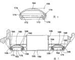
图4是图3中的旋风分离装置的密封件的透视图;Figure 4 is a perspective view of the seal of the cyclone separation device in Figure 3;
图5是图4中的密封件的侧截面图;Figure 5 is a side sectional view of the seal in Figure 4;
图6是图5中的一部分的放大图;Fig. 6 is an enlarged view of a part in Fig. 5;
图7是形成图3中的旋风分离装置的一部分的闭合部件的侧截面图;Figure 7 is a side sectional view of a closure member forming part of the cyclonic separation device in Figure 3;
图8是图3中的旋风分离装置的侧截面图,其中闭合部件处于打开状态;和Figure 8 is a side sectional view of the cyclonic separation device of Figure 3 with the closure member in an open position; and
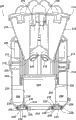
图9是根据本发明第二实施例的旋风分离装置的侧截面图。Fig. 9 is a side sectional view of a cyclone separation device according to a second embodiment of the present invention.
具体实施方式 Detailed ways
图1和2中示出了包括根据本发明第一实施例的旋风分离装置的圆筒式真空吸尘器10。真空吸尘器10具有主体12,该主体容纳电机和风扇单元(未示出)并且附连上一对轮子14。轮子14允许真空吸尘器10的主体12在地板表面上受操纵。脏空气入口16在主体12上形成。软管和杆组件(未示出)能连接到脏空气入口16,为了使得使用者能够清洁地板表面。A
根据本发明第一实施例的旋风分离装置100可拆卸地附在主体12上。旋风分离装置100的内部与脏空气入口16相通,载有污物的气流通过脏空气入口16进入旋风分离装置100。旋风分离装置100能从主体12移走以用于清空目的。The
在图3中更详细地示出了旋风分离装置100,其中为了清楚起见示出的旋风分离装置100从真空吸尘器10的其他部分移走。旋风分离装置100包括大体上圆柱形的外壁102。外壁102限定了第一旋风分离器104和第一收集器106。污物和尘土都被第一旋风分离器104分离并且收集在这个区域中的第一收集器106中。入口108形成在外壁102中。入口108在脏空气入口16与第一旋风分离器104的内部之间形成流通路径。空气入口108相对于第一旋风分离器104成切线地布置以使得进来的空气被迫沿着围绕外壁102的内部的螺旋形路径行进。The
外罩110位于第一旋风分离器104的外壁102的内部。外罩110包括具有多个通孔114的圆柱形壁112。外罩110包围第一旋风分离器104的出口116。出口116在第一旋风分离器104与第二旋风分离器118之间提供流通路径。凸缘120设置在外罩110的底部。凸缘120有助于避免被分离的污物和尘土重新回到第一旋风分离器104的气流中。The
第二旋风分离器118包括单个旋风器(cyclone)122。单个旋风器122具有空气入口124和空气出口126,两者都位于单个旋风器122的第一端。锥形开口128设置在单个旋风器122的第二端。第二收集器130也位于单个旋风器122的第二端并与锥形开口128连通。第二收集器130由圆柱形壁132限定,壁132从单个旋风器122的外表面垂下去并且位于外罩110的内部。单个旋风器122的空气出口126与管134相通。管134在第二旋风分离器118与第三旋风分离器136之间提供了流通路径。The
第三旋风分离器136包括并行设置的多个高效旋风器138。在这个实施例中,设有十四个高效旋风器138。每个高效旋风器138具有成切线布置的空气入口140和空气出口142。每个空气入口140和空气出口142位于相应的高效旋风器138的第一端。锥形开口(未示出)位于每个高效旋风器138的第二端。The
第三收集器144位于高效旋风器138的第二端并且与高效旋风器138的锥形开口相通。第三收集器144由圆柱形壁132和圆柱形壁146限定,圆柱形壁146位于外罩110与圆柱形壁132之间。圆柱形壁146从外罩110的上部垂下,并且在圆柱形壁146向下大约一半长度的点上也连到外罩。因此,第三收集器144是位于第一收集器106与第二收集器130之间的环形室。The
第一收集器106、第二收集器130和第三收集器144同心排列。第二收集器130和第三收集器144布置在第一收集器106里面。第二收集器130也布置在第三收集器144里面。收集器106、130、144的末端被分隔壁132、146分开。第一收集器106和第三收集器144的末端被圆柱形壁146分开,并且第二收集器130和第三收集器144的末端被圆柱形壁132分开。The
高效旋风器138的空气出口142与出口148相通。出口148提供从旋风分离装置100进入真空吸尘器10的其它部分的气流通路。位于出口148下游的是电机前过滤器(未示出)、电机和风扇单元以及电机后过滤器(未示出)。The
闭合部件150关闭旋风分离装置100的下端。闭合部件150通过铰链152可枢转地安装在外壁102的下端。闭合部件150通过锁扣154保持在关闭位置(如图3所示)。闭合部件150包括底部155和延伸到第二收集器130中的内部环形壁156。内部环形壁156有助于降低被第二旋风分离器118的单个旋风器122分离的污物和尘土再次被带入到单个旋风器122的气流中的风险。The
闭合部件150还包括另外的四个环形壁158,该环形壁158与内部环形壁156同心并且布置在内部环形壁156径向外面。相邻的环形壁158界定三个同心的环形通道160、162、164。三个环形通道160、162、164包括被两个相对窄的通道160、164从侧面包围的相对宽的通道162。The
环形密封件166附着到闭合部件150上。环形密封件166更详细地示出在图4到6中。在这些图中,示出的环形密封件166从旋风分离装置100的其它部分上被移走。环形密封件166具有凸起的上表面168和两个从上表面垂下的侧壁170。环形密封件166由诸如橡胶的柔性材料制成。An
凸起的上表面168朝着其最上部具有增加的厚度。侧壁170在其内表面172和外表面174上都具有锯齿轮廓。这更清楚地示于图6中。在内表面172上,锯齿轮廓包括两个齿,其在侧壁170的内表面172附近限定了两个环绕凹槽。在外表面174上的锯齿轮廓包括四个更小的齿,其在外表面174附近限定了四个环绕凹槽。The raised
图7示出了闭合部件150的剖面图,其中环形密封件166附着在其上。环形密封件166的每个侧壁170分别位于闭合部件150的相对窄的环形通道160、164中。通过环形密封件166的侧壁170的内表面172和外表面174上的齿与闭合部件150的环形壁158相配合,环形密封件166保持在合适的位置。结果,环形密封件166的上表面168盖住闭合部件150的相对宽的环形通道162以确定空腔175。Figure 7 shows a cross-sectional view of the
多个通孔176(尽管在图7中仅示出了一个)形成在闭合部件150的底部155上,以在空腔175与外界大气之间提供流通路经。因此,空腔175将保持在大气压下,而与旋风分离装置100的内部压力无关。但是,由于旋风分离装置100中的气流的速度,旋风分离装置100中的压力将低于大气压,导致压降越过环形密封件166的上表面168。由于环形密封件166的柔性性质,环形密封件166取决于越过其凸起的上表面168所建立的压差大小而改变形状。换句话说,环形密封件166是可膨胀的密封件,这是因为当相对于旋风分离装置100在空腔中具有正压力时,环形密封件166能扩张或膨胀。下面将更详细的描述环形密封件166的操作。A plurality of through holes 176 (although only one is shown in FIG. 7 ) are formed in the
图7中示出的环形密封件166处于“释放”位置,其中越过环形密封件166的凸起的上表面168没有压差。当闭合部件150关闭(如图3所示)时,环形密封件166的上表面168将被圆柱形壁132、146的端部压缩,建立闭合部件150与三个收集器106、130、144之间的密封,即使越过环形密封件166的上表面168没有压降也是如此。The
使用时,电机和风扇单元牵引通过软管和杆的含有污物的气流进入脏空气入口16,通过入口108并进入旋风分离装置100。由于入口108的切线布置,气流被迫使沿环绕外壁102内部的螺旋形通道行进。因此,大的污物和尘土颗粒被第一旋风分离器104的气旋运动所分离。这些颗粒收集在第一收集器106中。In use, the motor and fan unit draws a dirt-laden airflow through the hose and wand into the
部分清洁的气流然后流回第一旋风分离器104的内部,并通过外罩110中的通孔114离开第一旋风分离器104。一旦气流流过外罩110,气流进入出口116并从那里进入第二旋风分离器118的单个旋风器122的入口124。单个旋风器122具有小于第一旋风分离器104的外壁102的直径并且成锥形。因此,单个旋风器122能比第一旋风分离器104从部分清洁的气流中分离更小的污物和尘土颗粒。被分离的污物和尘土通过锥形开口128排出单个旋风器122,并收集在第二收集器130中。干净空气于是流回到单个旋风器122的中心,通过空气出口126离开单个旋风器122并流入管134。The partially cleaned gas stream then flows back into the interior of the
从管134,气流然后在第三旋风分离器136的高效旋风器138的切线空气入口140之间被分开。每个高效旋风器138的直径既小于第一旋风分离器104的直径又小于第二旋风分离器118的单个旋风器122的直径。因此,高效旋风器138能比第一旋风分离器104或第二旋风分离器118从气流中分离更细小的污物和尘土颗粒。被分离的污物和尘土通过锥形开口离开高效旋风器138并进入第四收集器144,并在第四收集器144中被收集。From
于是干净空气流回高效旋风器138,通过空气出口142离开高效旋风器138并进入出口148。随后,干净空气在从真空吸尘器10通过位于真空吸尘器10的外表面上的气孔(未示出)被排出之前,从出口148依次穿过电机前过滤器、电机与风扇单元和电机后过滤器。The clean air then flows back to the
当真空吸尘器10在使用并且旋风分离装置100在工作时,旋风分离装置100中气流的速度大于围绕真空吸尘器10的外界大气的速度。因此,旋风分离装置100中的气压低于大气压。从而,将会有压降(或压差)越过环形密封件166的凸起上表面168。环形密封件166下方的空腔175中的压力相对于旋风分离装置100中的压力为正。这将使环形密封件166扩张或膨胀,并且向上推动抵靠两个圆柱形壁132、146的端部。因此,即使当真空吸尘器10关闭时,收集器106、130、144没有被完全地密封,例如,由于用旧的密封件、未对准的闭合部件150或在环形密封件166与圆柱形壁132、146之间出现污物和尘土,环形密封件166也能在三个单独的收集器106、130、144之间有效地密封。When the
当清洁操作完成时,旋风分离装置100的收集器106、130、144可能充满污物和尘土,并需要清空。为此,使用者关闭真空吸尘器10。当真空吸尘器10关闭时,旋风分离装置100中的气压将回到大气压。因此,没有压降越过环形密封件166的上表面168,因此环形密封件166将缩小或紧缩。When the cleaning operation is complete, the
使用者通过按压释放按钮(未示出)把旋风分离装置100从主体12释放,把旋风分离装置100从真空吸尘器10的其它部分移走,并把该旋风分离装置放在合适的诸如垃圾箱的容器中。然后,使用者按压另一释放按钮(未示出)以松开锁扣154。The user releases the
如图8所示,这个动作释放闭合部件150,把闭合部件150推离壁102并允许闭合部件150绕铰链152向下枢转。因为环形密封件166缩小,闭合部件150能够容易地打开。收集在第一收集器106、第二收集器130和第三收集器144中的污物和尘土于是能够被方便地且有效地清空。在这个过程期间,第一收集器106、第二收集器130和第三收集器144被同时清空。As shown in FIG. 8 , this action releases the
当旋风分离装置100如上所述被清空时,使用者手动地将闭合部件150移回图3中所述的关闭位置。为了进一步的清洁操作,旋风分离装置100能被放回到真空吸尘器10的主体12上(如图1和2所示)。When the
图9示出了根据本发明第二实施例的旋风分离装置200的侧截面图。旋风分离装置200适合代替第一实施例中的旋风分离装置100用于图1中的真空吸尘器10。该旋风分离装置200与第一实施例中的旋风分离装置100的不同之处在于旋风分离装置200仅具有两个旋风分离器。Fig. 9 shows a side sectional view of a
该旋风分离装置200包括大致圆柱形的外壁202。外壁202限定了第一旋风分离器204和第一收集器206。入口208形成在外壁202上。该入口208以与第一实施例中的入口108同样的方式,相对于第一旋风分离器204成切线地布置。The
外罩210位于外壁202的内部。该外罩210与第一实施例中的外罩110相似,因此不再进一步描述。通路212位于外罩210的下游并且在第一旋风分离器204和第二旋风分离器214之间提供流通路径。The
第二旋风分离器214包括多个并行设置的高效旋风器216。在该实施例中,提供了六个高效旋风器216。每一个高效旋风器216具有与第二收集器220连通的锥形开口218。第二收集器220由从外罩210的下部分垂下的圆柱形壁222界定。第一收集器206和第二收集器220同心设置,并且第二收集器220设置在第一收集器206的内部。收集器206、220的端部由分隔壁222分开。The
闭合部件224封闭旋风分离装置200的下端。该闭合部件224以与第一实施例中的闭合部件150相似的方式可枢转地安装在外壁202的下端。该闭合部件224包括四个环形壁226,其界定了三个同心的环形通道228、230、232。三个环形通道228、230、232包括由两个相对窄的通道228、232从侧面围绕的相对宽的通道230。The closing
环形密封件234附着到闭合部件224上。环形密封件234与第一实施例中的环形密封件166相同。然而,在这个实施例中,该环形密封件234仅仅在闭合部件224和单独的分隔壁222之间密封。如前所述,环形密封件234的上表面236覆盖闭合部件224的相对宽的环形通道230,以限定空腔238。多个通孔240(尽管在图9中仅示出了一个)形成在闭合部件224中,以在空腔238和外界大气之间提供流通路径。因此,该空腔238将保持在大气压下,而与旋风分离装置200的内部压力无关。An
图9中示出的环形密封件234位于“释放”位置,其中越过环形密封件234的上表面236没有压差。然而,如第一实施例中的环形密封件166类似,该环形密封件234将取决于在真空吸尘器10接通时越过环形密封件的上表面236的压差数值而改变形状。The
使用时,载有污物和尘土的空气流通过入口208进入旋风分离装置200。较大的污物和尘土颗粒通过旋风运动而在第一旋风分离器204内被分离,并且这些颗粒收集在第一收集器206中。部分清洁的空气流经由外罩210中的通孔(未示出)离开第一旋风分离器204,并在第二旋风分离器214的多个高效旋风器216之间被分隔。污物和尘土在高效旋风器216中被分离,并且经由锥形开口218离开以收集在第二收集器220中。清洁的空气于是返回通过多个高效旋风器216,并且离开旋风分离装置200。旋风分离装置200的剩余部分的操作与第一实施例中描述的旋风分离装置100的操作相同。In use, a dirt and dust laden air stream enters the
当真空吸尘器10在使用并且旋风分离装置200在工作时,环形密封件234下方的空腔238中的压力相对于旋风分离装置200中的压力为正。因此,环形密封件234将扩张,上表面236将被向上推动以密封分隔壁222的端部。因此,即使当真空吸尘器10关闭时收集器206、220没有被完全地密封,环形密封件236也能在两个单独的收集器206、220之间有效地密封。When the
本发明不限于上面给出的详细说明。对本领域技术人员而言各种变化是显而易见的。例如,可以使用其他类型的可膨胀密封件;响应于越过密封件表面的压差,密封件不需要可扩张或者可膨胀。例如,可以使用加热时膨胀的可热膨胀密封件。另外,密封件不必是环形的。可以使用其他的布置,例如方形、矩形或者圆柱形。密封件也可以采取片状的形式。The invention is not limited to the detailed description given above. Various changes will be apparent to those skilled in the art. For example, other types of expandable seals may be used; the seal need not be expandable or inflatable in response to a pressure differential across the surface of the seal. For example, thermally expandable seals that expand when heated may be used. Additionally, the seal does not have to be annular. Other arrangements may be used, such as square, rectangular or cylindrical. The seal may also take the form of a sheet.
可以使用多于一个的密封件;例如,单独的可膨胀密封件可以位于每个分隔壁和闭合部件之间。另外,密封件不必位于闭合部件上。可以使用其他布置;例如,密封件可以位于收集器之间的分隔壁的端部上,或可以位于分隔壁和闭合部件之间的分离部件上。More than one seal may be used; for example, a separate expandable seal may be located between each dividing wall and closure member. In addition, the seal does not have to be on the closure part. Other arrangements may be used; for example, the seal may be located on the end of the partition wall between the collectors, or may be located on a separate part between the partition wall and the closure part.
旋风分离装置的除了基座之外的部分可移动用于清空目的。也可以使用其他形式、排布和位置的闭合部件。例如,旋风分离装置的侧部或顶部能被移走(或打开)。此外,闭合部件不必能够枢转。对于闭合部件能使用其它打开设置;例如滑动、缩进或转动闭合部件。Parts of the cyclone apart from the base are removable for emptying purposes. Other forms, arrangements and locations of closure members may also be used. For example, the sides or top of the cyclone can be removed (or opened). Furthermore, the closure part does not have to be able to pivot. Other opening arrangements for the closure can be used; such as sliding, retracting or turning the closure.
可以设置多于三个的旋风分离器。另外,多于一个的收集器可以设置有旋风分离器。例如,可以提供两个旋风分离器,其中一个旋风分离器具有与其相关联的两个收集器。此外,在每个旋风分离器中可以使用任意数目的旋风器。More than three cyclones may be provided. Additionally, more than one collector may be provided with cyclones. For example, two cyclones may be provided, one of which has two collectors associated therewith. Furthermore, any number of cyclones may be used in each cyclone separator.
清洁设备不必是圆筒式真空吸尘器。本发明能应用于其他类型的真空吸尘器,例如直立式机器、杆式真空吸尘器或手持式吸尘器。此外,本发明能应用于其他类型的清洁设备,例如,干湿机(a wet and dry machine)或者地毯清洗机。The cleaning device does not have to be a cylinder vacuum cleaner. The invention can be applied to other types of vacuum cleaners, such as upright machines, stick vacuum cleaners or hand-held vacuum cleaners. Furthermore, the invention can be applied to other types of cleaning equipment, for example, a wet and dry machine or a carpet cleaning machine.
Claims (16)
Applications Claiming Priority (2)
| Application Number | Priority Date | Filing Date | Title |
|---|---|---|---|
| GB0720341.7A GB2453761B (en) | 2007-10-18 | 2007-10-18 | Cyclonic separating apparatus for a cleaning appliance |
| GB0720341.7 | 2007-10-18 |
Publications (2)
| Publication Number | Publication Date |
|---|---|
| CN101455543A true CN101455543A (en) | 2009-06-17 |
| CN101455543B CN101455543B (en) | 2011-05-11 |
Family
ID=38814013
Family Applications (1)
| Application Number | Title | Priority Date | Filing Date |
|---|---|---|---|
| CN2008101911849A Active CN101455543B (en) | 2007-10-18 | 2008-10-20 | Cyclonic separating apparatus for a cleaning appliance |
Country Status (8)
| Country | Link |
|---|---|
| US (1) | US7867307B2 (en) |
| EP (1) | EP2205137B1 (en) |
| JP (1) | JP4696320B2 (en) |
| KR (1) | KR101153986B1 (en) |
| CN (1) | CN101455543B (en) |
| AU (1) | AU2008313526C1 (en) |
| GB (1) | GB2453761B (en) |
| WO (1) | WO2009050428A1 (en) |
Cited By (2)
| Publication number | Priority date | Publication date | Assignee | Title |
|---|---|---|---|---|
| CN106993978A (en) * | 2016-01-22 | 2017-08-01 | 戴森技术有限公司 | Separator and vacuum cleaner |
| CN111067420A (en) * | 2014-08-07 | 2020-04-28 | 三星电子株式会社 | Dust collector and dust separating device applied to dust collector |
Families Citing this family (87)
| Publication number | Priority date | Publication date | Assignee | Title |
|---|---|---|---|---|
| CA2599303A1 (en) | 2007-08-29 | 2009-02-28 | Gbd Corp. | Surface cleaning apparatus |
| US9888817B2 (en) | 2014-12-17 | 2018-02-13 | Omachron Intellectual Property Inc. | Surface cleaning apparatus |
| US20210401246A1 (en) | 2016-04-11 | 2021-12-30 | Omachron Intellectual Property Inc. | Surface cleaning apparatus |
| US11857142B2 (en) | 2006-12-15 | 2024-01-02 | Omachron Intellectual Property Inc. | Surface cleaning apparatus having an energy storage member and a charger for an energy storage member |
| US10165912B2 (en) | 2006-12-15 | 2019-01-01 | Omachron Intellectual Property Inc. | Surface cleaning apparatus |
| US9192269B2 (en) | 2006-12-15 | 2015-11-24 | Omachron Intellectual Property Inc. | Surface cleaning apparatus |
| GB2453760A (en) * | 2007-10-18 | 2009-04-22 | Dyson Technology Ltd | Sealing on closure member of cyclone |
| GB2453949B (en) * | 2007-10-23 | 2012-03-28 | Hoover Ltd | Cyclonic separation apparatus |
| CA2658046A1 (en) * | 2009-03-11 | 2010-09-11 | G.B.D. Corp. | Surface cleaning apparatus |
| US9433332B2 (en) | 2013-02-27 | 2016-09-06 | Omachron Intellectual Property Inc. | Surface cleaning apparatus |
| US10722086B2 (en) | 2017-07-06 | 2020-07-28 | Omachron Intellectual Property Inc. | Handheld surface cleaning apparatus |
| US9265395B2 (en) | 2010-03-12 | 2016-02-23 | Omachron Intellectual Property Inc. | Surface cleaning apparatus |
| US12156626B2 (en) | 2009-03-13 | 2024-12-03 | Omachron Intellectual Property Inc. | Surface cleaning apparatus |
| US8418778B2 (en) | 2010-01-07 | 2013-04-16 | Black & Decker Inc. | Power screwdriver having rotary input control |
| US9475180B2 (en) | 2010-01-07 | 2016-10-25 | Black & Decker Inc. | Power tool having rotary input control |
| US9266178B2 (en) | 2010-01-07 | 2016-02-23 | Black & Decker Inc. | Power tool having rotary input control |
| US8402599B2 (en) | 2010-09-01 | 2013-03-26 | Techtronic Floor Care Technology Limited | Vacuum cleaner dirt cup and seal |
| US8689401B2 (en) * | 2011-02-18 | 2014-04-08 | Techtronic Floor Care Technology Limited | Vacuum cleaner dirt cup |
| RU2561331C2 (en) | 2011-04-15 | 2015-08-27 | Дайсон Текнолоджи Лимитед | Cyclone separator containing outlet valve passing between two adjacent cyclone elements |
| GB2490697B (en) * | 2011-05-11 | 2015-01-14 | Dyson Technology Ltd | A surface treating appliance |
| GB2492744B (en) | 2011-05-11 | 2014-12-24 | Dyson Technology Ltd | A multi-cyclonic surface treating appliance |
| GB2490692B (en) | 2011-05-11 | 2014-12-17 | Dyson Technology Ltd | A cyclonic surface treating appliance with multiple cyclones |
| GB2492743B (en) | 2011-05-11 | 2015-01-14 | Dyson Technology Ltd | A surface treating appliance |
| GB2490695B (en) | 2011-05-11 | 2015-01-14 | Dyson Technology Ltd | A surface treating appliance |
| GB2490696B (en) | 2011-05-11 | 2014-12-17 | Dyson Technology Ltd | A cyclonic surface treating appliance with multiple cyclones |
| GB2490693B (en) | 2011-05-11 | 2014-12-17 | Dyson Technology Ltd | A cyclonic surface treating appliance with multiple cyclones |
| GB2490694B (en) | 2011-05-11 | 2015-01-14 | Dyson Technology Ltd | A surface treating appliance |
| EP2631035B1 (en) | 2012-02-24 | 2019-10-16 | Black & Decker Inc. | Power tool |
| USD724799S1 (en) * | 2012-08-28 | 2015-03-17 | Samsung Electronics Co. Ltd. | Vacuum cleaner |
| USD709253S1 (en) * | 2012-08-28 | 2014-07-15 | Samsung Electronics Co., Ltd. | Vacuum cleaner |
| AU351202S (en) * | 2013-02-18 | 2013-10-16 | Dyson Technology Ltd | Vacuum cleaner |
| AU351204S (en) * | 2013-02-18 | 2013-10-16 | Dyson Technology Ltd | Part of a vacuum cleaner |
| AU351203S (en) * | 2013-02-18 | 2013-10-16 | Dyson Technology Ltd | Part of a vacuum cleaner |
| AU350544S (en) * | 2013-02-18 | 2013-09-02 | Dyson Technology Ltd | A vacuum cleaner |
| US9027198B2 (en) | 2013-02-27 | 2015-05-12 | G.B.D. Corp. | Surface cleaning apparatus |
| US9320401B2 (en) | 2013-02-27 | 2016-04-26 | Omachron Intellectual Property Inc. | Surface cleaning apparatus |
| US9591958B2 (en) | 2013-02-27 | 2017-03-14 | Omachron Intellectual Property Inc. | Surface cleaning apparatus |
| US20140237768A1 (en) | 2013-02-28 | 2014-08-28 | G.B.D. Corp. | Surface cleaning apparatus |
| JP1519889S (en) | 2013-12-20 | 2015-03-23 | ||
| USD767220S1 (en) | 2013-12-20 | 2016-09-20 | Dyson Technology Limited | Part of a vacuum cleaner |
| US10631697B2 (en) | 2014-02-14 | 2020-04-28 | Techtronic Industries Co. Ltd. | Separator configuration |
| US9585530B2 (en) | 2014-07-18 | 2017-03-07 | Omachron Intellectual Property Inc. | Portable surface cleaning apparatus |
| US9451853B2 (en) | 2014-07-18 | 2016-09-27 | Omachron Intellectual Property Inc. | Portable surface cleaning apparatus |
| US9420925B2 (en) | 2014-07-18 | 2016-08-23 | Omachron Intellectual Property Inc. | Portable surface cleaning apparatus |
| US9314139B2 (en) | 2014-07-18 | 2016-04-19 | Omachron Intellectual Property Inc. | Portable surface cleaning apparatus |
| WO2016021874A1 (en) * | 2014-08-07 | 2016-02-11 | Samsung Electronics Co., Ltd. | Cleaner and dust separating device applying the same |
| EP3209184A2 (en) | 2014-10-22 | 2017-08-30 | Techtronic Industries Company Limited | Vacuum cleaner having cyclonic separator |
| US9775483B2 (en) | 2014-10-22 | 2017-10-03 | Techtronic Industries Co. Ltd. | Vacuum cleaner having cyclonic separator |
| WO2016065151A1 (en) | 2014-10-22 | 2016-04-28 | Techtronic Industries Co. Ltd. | Handheld vacuum cleaner |
| KR101653459B1 (en) * | 2014-12-01 | 2016-09-01 | 엘지전자 주식회사 | Vacuum clenar and dust collecting apparatus |
| US10251519B2 (en) | 2014-12-17 | 2019-04-09 | Omachron Intellectual Property Inc. | Surface cleaning apparatus |
| US10136778B2 (en) | 2014-12-17 | 2018-11-27 | Omachron Intellectual Property Inc. | Surface cleaning apparatus |
| US11950745B2 (en) | 2014-12-17 | 2024-04-09 | Omachron Intellectual Property Inc. | Surface cleaning apparatus |
| KR101653481B1 (en) | 2015-01-16 | 2016-09-01 | 엘지전자 주식회사 | Vacuum cleaner and dust collecting apparatus |
| US9885196B2 (en) | 2015-01-26 | 2018-02-06 | Hayward Industries, Inc. | Pool cleaner power coupling |
| CA3146537C (en) | 2015-01-26 | 2023-01-03 | Hayward Industries, Inc. | Swimming pool cleaner with hydrocyclonic particle separator and/or six-roller drive system |
| US10080471B2 (en) | 2015-12-21 | 2018-09-25 | Electrolux Home Care Products, Inc. | Versatile vacuum cleaners |
| US10201260B2 (en) | 2016-04-25 | 2019-02-12 | Omachron Intellectual Property Inc. | Cyclone assembly for surface cleaning apparatus and a surface cleaning apparatus having same |
| US10149587B2 (en) | 2016-04-25 | 2018-12-11 | Omachron Intellectual Property Inc. | Cyclone assembly for surface cleaning apparatus and a surface cleaning apparatus having same |
| US10537219B2 (en) | 2016-04-25 | 2020-01-21 | Omachron Intellectual Property Inc. | Cyclone assembly for surface cleaning apparatus and a surface cleaning apparatus having same |
| US9936846B2 (en) * | 2016-04-25 | 2018-04-10 | Omachron Intellectual Property Inc. | Cyclone assembly for surface cleaning apparatus and a surface cleaning apparatus having same |
| US10251521B2 (en) | 2016-04-25 | 2019-04-09 | Omachron Intellectual Property Inc. | Cyclone assembly for surface cleaning apparatus and a surface cleaning apparatus having same |
| USD813475S1 (en) | 2016-06-01 | 2018-03-20 | Milwaukee Electric Tool Corporation | Handheld vacuum cleaner |
| KR102306705B1 (en) | 2016-08-25 | 2021-09-30 | 엘지전자 주식회사 | Cleaner |
| US9896858B1 (en) | 2017-05-11 | 2018-02-20 | Hayward Industries, Inc. | Hydrocyclonic pool cleaner |
| US10156083B2 (en) | 2017-05-11 | 2018-12-18 | Hayward Industries, Inc. | Pool cleaner power coupling |
| US9885194B1 (en) | 2017-05-11 | 2018-02-06 | Hayward Industries, Inc. | Pool cleaner impeller subassembly |
| CN111031869B (en) * | 2017-06-19 | 2022-04-12 | 创科(澳门离岸商业服务)有限公司 | Cyclone Separator Unit |
| GB2563664B (en) * | 2017-06-23 | 2019-09-04 | Dyson Technology Ltd | Separating apparatus and vacuum cleaner |
| US11766156B2 (en) | 2020-03-18 | 2023-09-26 | Omachron Intellectual Property Inc. | Surface cleaning apparatus with removable air treatment member assembly |
| US10702113B2 (en) | 2017-07-06 | 2020-07-07 | Omachron Intellectual Property Inc. | Handheld surface cleaning apparatus |
| US11730327B2 (en) | 2020-03-18 | 2023-08-22 | Omachron Intellectual Property Inc. | Surface cleaning apparatus with removable air treatment assembly |
| US11445878B2 (en) | 2020-03-18 | 2022-09-20 | Omachron Intellectual Property Inc. | Surface cleaning apparatus with removable air treatment member assembly |
| US10842330B2 (en) | 2017-07-06 | 2020-11-24 | Omachron Intellectual Property Inc. | Handheld surface cleaning apparatus |
| US10537216B2 (en) | 2017-07-06 | 2020-01-21 | Omachron Intellectual Property Inc. | Handheld surface cleaning apparatus |
| US10631693B2 (en) | 2017-07-06 | 2020-04-28 | Omachron Intellectual Property Inc. | Handheld surface cleaning apparatus |
| US11666193B2 (en) | 2020-03-18 | 2023-06-06 | Omachron Intellectual Property Inc. | Surface cleaning apparatus with removable air treatment member assembly |
| US10506904B2 (en) | 2017-07-06 | 2019-12-17 | Omachron Intellectual Property Inc. | Handheld surface cleaning apparatus |
| US10750913B2 (en) | 2017-07-06 | 2020-08-25 | Omachron Intellectual Property Inc. | Handheld surface cleaning apparatus |
| US10882059B2 (en) | 2018-09-21 | 2021-01-05 | Omachron Intellectual Property Inc. | Multi cyclone array for surface cleaning apparatus and a surface cleaning apparatus having same |
| US11006799B2 (en) | 2018-08-13 | 2021-05-18 | Omachron Intellectual Property Inc. | Cyclonic air treatment member and surface cleaning apparatus including the same |
| US11013384B2 (en) | 2018-08-13 | 2021-05-25 | Omachron Intellectual Property Inc. | Cyclonic air treatment member and surface cleaning apparatus including the same |
| US11192122B2 (en) | 2018-08-13 | 2021-12-07 | Omachron Intellectual Property Inc. | Cyclonic air treatment member and surface cleaning apparatus including the same |
| EP4120883A4 (en) | 2020-03-18 | 2024-03-27 | Omachron Intellectual Property Inc. | Surface cleaning apparatus with removable air treatment member assembly |
| US20210386258A1 (en) | 2020-03-18 | 2021-12-16 | Omachron Intellectual Property Inc. | Surface cleaning apparatus |
| CN112122019B (en) * | 2020-09-02 | 2021-10-15 | 东莞福莱仕智能电子科技有限公司 | Cyclone separation device and cleaning equipment |
| CN215128031U (en) * | 2021-03-11 | 2021-12-14 | 北京顺造科技有限公司 | A cyclone separation device |
Family Cites Families (12)
| Publication number | Priority date | Publication date | Assignee | Title |
|---|---|---|---|---|
| US3486618A (en) * | 1966-09-13 | 1969-12-30 | Nils Anders Lennart Wikdahl | Multiple-cyclone separator installation |
| US4687497A (en) * | 1986-09-29 | 1987-08-18 | Mobil Oil Corporation | Solids-gas separator |
| US5000767A (en) * | 1990-05-30 | 1991-03-19 | Pneumafil Corporation | Dust collector with pneumatic seal |
| GB2360719B (en) | 2000-03-31 | 2003-04-30 | Notetry Ltd | A domestic vacuum cleaner for separating particles from a fluid flow |
| US6607572B2 (en) * | 2001-02-24 | 2003-08-19 | Dyson Limited | Cyclonic separating apparatus |
| CN1290467C (en) * | 2001-02-24 | 2006-12-20 | 戴森技术有限公司 | Collecting chamber for a vacuum cleaner |
| JP3659191B2 (en) | 2001-05-08 | 2005-06-15 | 松下電器産業株式会社 | Centrifugal dust collector and electric vacuum cleaner using the same |
| JP3846559B2 (en) | 2001-11-21 | 2006-11-15 | Nok株式会社 | accumulator |
| US6829804B2 (en) | 2002-03-26 | 2004-12-14 | White Consolidated, Ltd. | Filtration arrangement of a vacuum cleaner |
| JP2004229827A (en) | 2003-01-29 | 2004-08-19 | Sanyo Electric Co Ltd | Dust collecting device and vacuum cleaner using it |
| KR20070012988A (en) * | 2005-07-25 | 2007-01-30 | 엘지전자 주식회사 | Dust collection unit |
| GB2441300B (en) | 2006-09-01 | 2011-10-12 | Dyson Technology Ltd | A collecting chamber for a vacuum cleaner |
-
2007
- 2007-10-18 GB GB0720341.7A patent/GB2453761B/en active Active
-
2008
- 2008-10-01 US US12/243,484 patent/US7867307B2/en active Active
- 2008-10-06 AU AU2008313526A patent/AU2008313526C1/en active Active
- 2008-10-06 KR KR1020107008891A patent/KR101153986B1/en active Active
- 2008-10-06 EP EP08806518.0A patent/EP2205137B1/en active Active
- 2008-10-06 WO PCT/GB2008/003376 patent/WO2009050428A1/en not_active Ceased
- 2008-10-17 JP JP2008268779A patent/JP4696320B2/en active Active
- 2008-10-20 CN CN2008101911849A patent/CN101455543B/en active Active
Cited By (3)
| Publication number | Priority date | Publication date | Assignee | Title |
|---|---|---|---|---|
| CN111067420A (en) * | 2014-08-07 | 2020-04-28 | 三星电子株式会社 | Dust collector and dust separating device applied to dust collector |
| CN111067420B (en) * | 2014-08-07 | 2022-11-29 | 三星电子株式会社 | Dust collector and dust separating device applied to dust collector |
| CN106993978A (en) * | 2016-01-22 | 2017-08-01 | 戴森技术有限公司 | Separator and vacuum cleaner |
Also Published As
| Publication number | Publication date |
|---|---|
| JP2009095678A (en) | 2009-05-07 |
| KR101153986B1 (en) | 2012-06-07 |
| AU2008313526C1 (en) | 2011-11-24 |
| GB2453761B (en) | 2012-04-18 |
| EP2205137A1 (en) | 2010-07-14 |
| US20090100633A1 (en) | 2009-04-23 |
| WO2009050428A1 (en) | 2009-04-23 |
| AU2008313526B2 (en) | 2011-06-30 |
| GB0720341D0 (en) | 2007-11-28 |
| KR20100075537A (en) | 2010-07-02 |
| GB2453761A (en) | 2009-04-22 |
| US7867307B2 (en) | 2011-01-11 |
| CN101455543B (en) | 2011-05-11 |
| AU2008313526A1 (en) | 2009-04-23 |
| JP4696320B2 (en) | 2011-06-08 |
| EP2205137B1 (en) | 2014-11-19 |
Similar Documents
| Publication | Publication Date | Title |
|---|---|---|
| CN101455543B (en) | Cyclonic separating apparatus for a cleaning appliance | |
| CN101455544B (en) | Cyclonic separating apparatus for a cleaning appliance | |
| CN101511250B (en) | A collection chamber for a vacuum cleaner | |
| CN101297747B (en) | Collecting chamber for a cleaning appliance | |
| CN206612746U (en) | Cyclone module and vacuum cleaner for vacuum cleaner | |
| AU2008320617B2 (en) | Cyclonic separating apparatus | |
| AU2007274888B2 (en) | Handheld cleaning appliance | |
| AU2003285554B2 (en) | Cyclonic separators for suction cleaners | |
| JP2003339596A (en) | Dust collecting apparatus and vacuum cleaner | |
| JP2003339593A (en) | Vacuum cleaner | |
| EP1195125A2 (en) | Vacuum cleaner with 2-stage separation |
Legal Events
| Date | Code | Title | Description |
|---|---|---|---|
| C06 | Publication | ||
| PB01 | Publication | ||
| C10 | Entry into substantive examination | ||
| SE01 | Entry into force of request for substantive examination | ||
| C14 | Grant of patent or utility model | ||
| GR01 | Patent grant |