CN101454943A - Glass pane having soldered electrical terminal connections - Google Patents
Glass pane having soldered electrical terminal connections Download PDFInfo
- Publication number
- CN101454943A CN101454943A CNA2007800178568A CN200780017856A CN101454943A CN 101454943 A CN101454943 A CN 101454943A CN A2007800178568 A CNA2007800178568 A CN A2007800178568A CN 200780017856 A CN200780017856 A CN 200780017856A CN 101454943 A CN101454943 A CN 101454943A
- Authority
- CN
- China
- Prior art keywords
- glass plate
- metal derby
- terminal region
- terminal
- metal
- Prior art date
- Legal status (The legal status is an assumption and is not a legal conclusion. Google has not performed a legal analysis and makes no representation as to the accuracy of the status listed.)
- Pending
Links
Images

Classifications
-
- B—PERFORMING OPERATIONS; TRANSPORTING
- B60—VEHICLES IN GENERAL
- B60S—SERVICING, CLEANING, REPAIRING, SUPPORTING, LIFTING, OR MANOEUVRING OF VEHICLES, NOT OTHERWISE PROVIDED FOR
- B60S1/00—Cleaning of vehicles
- B60S1/02—Cleaning windscreens, windows or optical devices
-
- H—ELECTRICITY
- H01—ELECTRIC ELEMENTS
- H01R—ELECTRICALLY-CONDUCTIVE CONNECTIONS; STRUCTURAL ASSOCIATIONS OF A PLURALITY OF MUTUALLY-INSULATED ELECTRICAL CONNECTING ELEMENTS; COUPLING DEVICES; CURRENT COLLECTORS
- H01R4/00—Electrically-conductive connections between two or more conductive members in direct contact, i.e. touching one another; Means for effecting or maintaining such contact; Electrically-conductive connections having two or more spaced connecting locations for conductors and using contact members penetrating insulation
- H01R4/02—Soldered or welded connections
- H01R4/023—Soldered or welded connections between cables or wires and terminals
-
- B—PERFORMING OPERATIONS; TRANSPORTING
- B32—LAYERED PRODUCTS
- B32B—LAYERED PRODUCTS, i.e. PRODUCTS BUILT-UP OF STRATA OF FLAT OR NON-FLAT, e.g. CELLULAR OR HONEYCOMB, FORM
- B32B17/00—Layered products essentially comprising sheet glass, or glass, slag, or like fibres
- B32B17/06—Layered products essentially comprising sheet glass, or glass, slag, or like fibres comprising glass as the main or only constituent of a layer, next to another layer of a specific material
- B32B17/10—Layered products essentially comprising sheet glass, or glass, slag, or like fibres comprising glass as the main or only constituent of a layer, next to another layer of a specific material of synthetic resin
- B32B17/10005—Layered products essentially comprising sheet glass, or glass, slag, or like fibres comprising glass as the main or only constituent of a layer, next to another layer of a specific material of synthetic resin laminated safety glass or glazing
- B32B17/10009—Layered products essentially comprising sheet glass, or glass, slag, or like fibres comprising glass as the main or only constituent of a layer, next to another layer of a specific material of synthetic resin laminated safety glass or glazing characterized by the number, the constitution or treatment of glass sheets
- B32B17/10036—Layered products essentially comprising sheet glass, or glass, slag, or like fibres comprising glass as the main or only constituent of a layer, next to another layer of a specific material of synthetic resin laminated safety glass or glazing characterized by the number, the constitution or treatment of glass sheets comprising two outer glass sheets
-
- B—PERFORMING OPERATIONS; TRANSPORTING
- B32—LAYERED PRODUCTS
- B32B—LAYERED PRODUCTS, i.e. PRODUCTS BUILT-UP OF STRATA OF FLAT OR NON-FLAT, e.g. CELLULAR OR HONEYCOMB, FORM
- B32B17/00—Layered products essentially comprising sheet glass, or glass, slag, or like fibres
- B32B17/06—Layered products essentially comprising sheet glass, or glass, slag, or like fibres comprising glass as the main or only constituent of a layer, next to another layer of a specific material
- B32B17/10—Layered products essentially comprising sheet glass, or glass, slag, or like fibres comprising glass as the main or only constituent of a layer, next to another layer of a specific material of synthetic resin
- B32B17/10005—Layered products essentially comprising sheet glass, or glass, slag, or like fibres comprising glass as the main or only constituent of a layer, next to another layer of a specific material of synthetic resin laminated safety glass or glazing
- B32B17/10165—Functional features of the laminated safety glass or glazing
- B32B17/10174—Coatings of a metallic or dielectric material on a constituent layer of glass or polymer
-
- B—PERFORMING OPERATIONS; TRANSPORTING
- B32—LAYERED PRODUCTS
- B32B—LAYERED PRODUCTS, i.e. PRODUCTS BUILT-UP OF STRATA OF FLAT OR NON-FLAT, e.g. CELLULAR OR HONEYCOMB, FORM
- B32B17/00—Layered products essentially comprising sheet glass, or glass, slag, or like fibres
- B32B17/06—Layered products essentially comprising sheet glass, or glass, slag, or like fibres comprising glass as the main or only constituent of a layer, next to another layer of a specific material
- B32B17/10—Layered products essentially comprising sheet glass, or glass, slag, or like fibres comprising glass as the main or only constituent of a layer, next to another layer of a specific material of synthetic resin
- B32B17/10005—Layered products essentially comprising sheet glass, or glass, slag, or like fibres comprising glass as the main or only constituent of a layer, next to another layer of a specific material of synthetic resin laminated safety glass or glazing
- B32B17/10165—Functional features of the laminated safety glass or glazing
- B32B17/10293—Edge features, e.g. inserts or holes
-
- B—PERFORMING OPERATIONS; TRANSPORTING
- B32—LAYERED PRODUCTS
- B32B—LAYERED PRODUCTS, i.e. PRODUCTS BUILT-UP OF STRATA OF FLAT OR NON-FLAT, e.g. CELLULAR OR HONEYCOMB, FORM
- B32B17/00—Layered products essentially comprising sheet glass, or glass, slag, or like fibres
- B32B17/06—Layered products essentially comprising sheet glass, or glass, slag, or like fibres comprising glass as the main or only constituent of a layer, next to another layer of a specific material
- B32B17/10—Layered products essentially comprising sheet glass, or glass, slag, or like fibres comprising glass as the main or only constituent of a layer, next to another layer of a specific material of synthetic resin
- B32B17/10005—Layered products essentially comprising sheet glass, or glass, slag, or like fibres comprising glass as the main or only constituent of a layer, next to another layer of a specific material of synthetic resin laminated safety glass or glazing
- B32B17/1055—Layered products essentially comprising sheet glass, or glass, slag, or like fibres comprising glass as the main or only constituent of a layer, next to another layer of a specific material of synthetic resin laminated safety glass or glazing characterized by the resin layer, i.e. interlayer
- B32B17/10761—Layered products essentially comprising sheet glass, or glass, slag, or like fibres comprising glass as the main or only constituent of a layer, next to another layer of a specific material of synthetic resin laminated safety glass or glazing characterized by the resin layer, i.e. interlayer containing vinyl acetal
-
- H—ELECTRICITY
- H01—ELECTRIC ELEMENTS
- H01R—ELECTRICALLY-CONDUCTIVE CONNECTIONS; STRUCTURAL ASSOCIATIONS OF A PLURALITY OF MUTUALLY-INSULATED ELECTRICAL CONNECTING ELEMENTS; COUPLING DEVICES; CURRENT COLLECTORS
- H01R12/00—Structural associations of a plurality of mutually-insulated electrical connecting elements, specially adapted for printed circuits, e.g. printed circuit boards [PCB], flat or ribbon cables, or like generally planar structures, e.g. terminal strips, terminal blocks; Coupling devices specially adapted for printed circuits, flat or ribbon cables, or like generally planar structures; Terminals specially adapted for contact with, or insertion into, printed circuits, flat or ribbon cables, or like generally planar structures
- H01R12/50—Fixed connections
- H01R12/51—Fixed connections for rigid printed circuits or like structures
- H01R12/55—Fixed connections for rigid printed circuits or like structures characterised by the terminals
- H01R12/57—Fixed connections for rigid printed circuits or like structures characterised by the terminals surface mounting terminals
-
- H—ELECTRICITY
- H01—ELECTRIC ELEMENTS
- H01R—ELECTRICALLY-CONDUCTIVE CONNECTIONS; STRUCTURAL ASSOCIATIONS OF A PLURALITY OF MUTUALLY-INSULATED ELECTRICAL CONNECTING ELEMENTS; COUPLING DEVICES; CURRENT COLLECTORS
- H01R4/00—Electrically-conductive connections between two or more conductive members in direct contact, i.e. touching one another; Means for effecting or maintaining such contact; Electrically-conductive connections having two or more spaced connecting locations for conductors and using contact members penetrating insulation
- H01R4/10—Electrically-conductive connections between two or more conductive members in direct contact, i.e. touching one another; Means for effecting or maintaining such contact; Electrically-conductive connections having two or more spaced connecting locations for conductors and using contact members penetrating insulation effected solely by twisting, wrapping, bending, crimping, or other permanent deformation
- H01R4/18—Electrically-conductive connections between two or more conductive members in direct contact, i.e. touching one another; Means for effecting or maintaining such contact; Electrically-conductive connections having two or more spaced connecting locations for conductors and using contact members penetrating insulation effected solely by twisting, wrapping, bending, crimping, or other permanent deformation by crimping
- H01R4/20—Electrically-conductive connections between two or more conductive members in direct contact, i.e. touching one another; Means for effecting or maintaining such contact; Electrically-conductive connections having two or more spaced connecting locations for conductors and using contact members penetrating insulation effected solely by twisting, wrapping, bending, crimping, or other permanent deformation by crimping using a crimping sleeve
-
- H—ELECTRICITY
- H01—ELECTRIC ELEMENTS
- H01R—ELECTRICALLY-CONDUCTIVE CONNECTIONS; STRUCTURAL ASSOCIATIONS OF A PLURALITY OF MUTUALLY-INSULATED ELECTRICAL CONNECTING ELEMENTS; COUPLING DEVICES; CURRENT COLLECTORS
- H01R43/00—Apparatus or processes specially adapted for manufacturing, assembling, maintaining, or repairing of line connectors or current collectors or for joining electric conductors
- H01R43/02—Apparatus or processes specially adapted for manufacturing, assembling, maintaining, or repairing of line connectors or current collectors or for joining electric conductors for soldered or welded connections
- H01R43/0256—Apparatus or processes specially adapted for manufacturing, assembling, maintaining, or repairing of line connectors or current collectors or for joining electric conductors for soldered or welded connections for soldering or welding connectors to a printed circuit board
-
- H—ELECTRICITY
- H01—ELECTRIC ELEMENTS
- H01R—ELECTRICALLY-CONDUCTIVE CONNECTIONS; STRUCTURAL ASSOCIATIONS OF A PLURALITY OF MUTUALLY-INSULATED ELECTRICAL CONNECTING ELEMENTS; COUPLING DEVICES; CURRENT COLLECTORS
- H01R9/00—Structural associations of a plurality of mutually-insulated electrical connecting elements, e.g. terminal strips or terminal blocks; Terminals or binding posts mounted upon a base or in a case; Bases therefor
- H01R9/11—End pieces for multiconductor cables supported by the cable and for facilitating connections to other conductive members, e.g. for liquid cooled welding cables
-
- H—ELECTRICITY
- H05—ELECTRIC TECHNIQUES NOT OTHERWISE PROVIDED FOR
- H05B—ELECTRIC HEATING; ELECTRIC LIGHT SOURCES NOT OTHERWISE PROVIDED FOR; CIRCUIT ARRANGEMENTS FOR ELECTRIC LIGHT SOURCES, IN GENERAL
- H05B3/00—Ohmic-resistance heating
- H05B3/84—Heating arrangements specially adapted for transparent or reflecting areas, e.g. for demisting or de-icing windows, mirrors or vehicle windshields
-
- H—ELECTRICITY
- H05—ELECTRIC TECHNIQUES NOT OTHERWISE PROVIDED FOR
- H05K—PRINTED CIRCUITS; CASINGS OR CONSTRUCTIONAL DETAILS OF ELECTRIC APPARATUS; MANUFACTURE OF ASSEMBLAGES OF ELECTRICAL COMPONENTS
- H05K1/00—Printed circuits
- H05K1/02—Details
- H05K1/03—Use of materials for the substrate
- H05K1/0306—Inorganic insulating substrates, e.g. ceramic, glass
-
- H—ELECTRICITY
- H01—ELECTRIC ELEMENTS
- H01R—ELECTRICALLY-CONDUCTIVE CONNECTIONS; STRUCTURAL ASSOCIATIONS OF A PLURALITY OF MUTUALLY-INSULATED ELECTRICAL CONNECTING ELEMENTS; COUPLING DEVICES; CURRENT COLLECTORS
- H01R2201/00—Connectors or connections adapted for particular applications
- H01R2201/02—Connectors or connections adapted for particular applications for antennas
-
- H—ELECTRICITY
- H01—ELECTRIC ELEMENTS
- H01R—ELECTRICALLY-CONDUCTIVE CONNECTIONS; STRUCTURAL ASSOCIATIONS OF A PLURALITY OF MUTUALLY-INSULATED ELECTRICAL CONNECTING ELEMENTS; COUPLING DEVICES; CURRENT COLLECTORS
- H01R2201/00—Connectors or connections adapted for particular applications
- H01R2201/26—Connectors or connections adapted for particular applications for vehicles
-
- H—ELECTRICITY
- H05—ELECTRIC TECHNIQUES NOT OTHERWISE PROVIDED FOR
- H05B—ELECTRIC HEATING; ELECTRIC LIGHT SOURCES NOT OTHERWISE PROVIDED FOR; CIRCUIT ARRANGEMENTS FOR ELECTRIC LIGHT SOURCES, IN GENERAL
- H05B2203/00—Aspects relating to Ohmic resistive heating covered by group H05B3/00
- H05B2203/016—Heaters using particular connecting means
-
- H—ELECTRICITY
- H05—ELECTRIC TECHNIQUES NOT OTHERWISE PROVIDED FOR
- H05K—PRINTED CIRCUITS; CASINGS OR CONSTRUCTIONAL DETAILS OF ELECTRIC APPARATUS; MANUFACTURE OF ASSEMBLAGES OF ELECTRICAL COMPONENTS
- H05K3/00—Apparatus or processes for manufacturing printed circuits
- H05K3/30—Assembling printed circuits with electric components, e.g. with resistors
- H05K3/32—Assembling printed circuits with electric components, e.g. with resistors electrically connecting electric components or wires to printed circuits
- H05K3/34—Assembling printed circuits with electric components, e.g. with resistors electrically connecting electric components or wires to printed circuits by soldering
- H05K3/341—Surface mounted components
Landscapes
- Engineering & Computer Science (AREA)
- Manufacturing & Machinery (AREA)
- Chemical & Material Sciences (AREA)
- Ceramic Engineering (AREA)
- Inorganic Chemistry (AREA)
- Microelectronics & Electronic Packaging (AREA)
- Mechanical Engineering (AREA)
- Connections Effected By Soldering, Adhesion, Or Permanent Deformation (AREA)
- Resistance Heating (AREA)
- Surface Heating Bodies (AREA)
- Joining Of Glass To Other Materials (AREA)
Abstract
A glass pane having at least one electrical functional element is provided. The functional element comprises at least one electrical conductor (2) and at least one terminal area (3) located at an end of the electrical conductor (2), wherein the electrical conductor (2) and the terminal area (3) are formed from an electrically conductive layer deposited on a surface (4) of the glass pane. A terminal wire (5) is connected to the at least one terminal area (3) by means of a soldered joint by means of a metal block (6) having a flat contact area (7), and the flat contact area (7) is soldered on a corresponding terminal area (3). A method for forming such a connection is also disclosed.
Description
Technical field
The present invention relates to a kind of glass plate that is preferably used for motor vehicles, this glass plate has at least one electric functional elements, wherein, this electric functional elements comprises that at least one electric conductor and at least one are formed on the terminal region at the place, end of electric conductor, wherein, this electric conductor and terminal region are made of the conductive layer that is deposited on the glass pane surface, and terminal connections is connected to terminal region by welding point.In addition, the present invention relates to a kind of method of producing electrical terminal connections.
Background technology
Function element is appreciated that at this and comprises and utilize thick film technology or thin film technique to deposit the function element of one deck conductive layer at least on glass plate.The example of this function element is resistance heating conductor, alarm conductor (alarm conductor) and antenna conductor.But the glass plate with the such function element that begins to mention is as the heating plate in the windshield of for example motor vehicles, and wherein electric conductor is arranged as heating element in the windshield wiper heating field of lower area of windshield.But heating plate comprises the glass plate of lamination here, and the glass plate of this lamination comprises the float glass plate of at least two bendings, inserts at least one plastic film (as being made by PVB) between these two float glass plate.These glass plates connect together by heat treatment securely with film.Conductive layer deposition interior glass surface or outside in the glass surface one, and be configured to define at least one heater and be positioned at least two terminal region at the place, two ends of this heater.Usually between terminal region, form a plurality of heaters in parallel.In order to produce heater and terminal region, for example on glass surface, print and contain silver paste, then sintering by silk-screen printing technique.When on the outer surface of conductive layer deposition at laminated sheet, terminal region is arranged to and can freely arrives, and is usually located at the edge of the glass plate of lamination.If on one the interior glass surface of conductive layer deposition in glass plate, then corresponding another glass plate is provided with recess usually in the zone of terminal region, makes that terminal region keeps freely arriving.
Under a variety of situations, terminal line is welded on the terminal region.Terminal line generally includes a branch of thin metal-cored (so-called sweep (flex wire)), and this is metal-cored to be surrounded by plastic insulation, and increases the mechanical flexibility of terminal line.Terminal region is zinc-plated in advance usually, and in order between terminal line and terminal region, to produce the joint of welding, remove the plastic insulation (through after zinc-plated in advance, depending on the circumstances at terminal line) at the place, end of terminal line, the end of terminal line is soldered on the terminal region then.This manually carries out usually.
For fear of the glass plate of the lamination defective in the more multiprocessing of windshield for example, the mechanical connection between the terminal region of terminal line and heating element must can be resisted mechanical load.Especially, occurring under the situation of normal mechanical load, must not take place terminal line pull or the breaking of conductive layer.For example, require the separating force of minimum 30N for the heating field terminal.Have been found that general size and thickness of glass for terminal region, the welding point of producing by the way between the terminal region of terminal line and heating element always can not resisted these loads.Especially, always can not realize the separating force of required minimum 30N.
In order to improve the quality of welding point, proposed terminal line is fixed (for example welding) on metal forming or metal sheet, then the synthetic of this relatively large area (being made of terminal line and metal forming or metal sheet) has been welded on the terminal region of heating element.But this structure is not to show the required intensity of pulling equally.In addition, such terminal design is (and expensive) consuming time, and needs large-sized terminal region, and to this large-sized terminal region, sufficient space is not always arranged.
Summary of the invention
Therefore, problem of the present invention is to improve in cost-effective mode the mechanical strength of electric terminal, particularly improves and pulls intensity.
According to the present invention, address this problem by a kind of glass plate and a kind of method of producing electrical terminal connections with at least one electric functional elements, this electric functional elements has the feature of claim 1, and this method has the feature of claim 23.
According to the present invention, the glass plate with electric functional elements of the type that begins to mention is characterised in that at least one terminal line is fixed to the metal derby with flat contact area, and this flat contact area is welded on the terminal region.
Here, metal derby is interpreted as the finger metallic object, and it can be a hollow, and has good electrical conductivity and thermal conductivity that metal has usually.The external dimensions of metal derby has the roughly the same order of magnitude in all three Spatial Dimensions, that is, the neither one size reach another size on the orthogonal direction 1/10th or littler.Preferably, the difference of the size on the mutually orthogonal direction is not more than 5 times.Here flat contact area is interpreted as and refers to fully big contact zone of flatness, and is furnished with the solder layer (for example less than 0.2mm) of relatively little thickness betwixt, is furnished with the joint of terminal region below forming, and makes described joint extend in whole district.
What shown is, by the metal derby with flat contact area is fixed to terminal line and by welding on the flat contact area of metal derby, can realize pulling intensity well beyond 100N.This can be owing to the hot buffering effect and because the heat load that reduces of the glass surface that heat distribution (having reduced the local temperature peak value) produces of metal derby.These effects will be greater than the effect in the thin foil of prior art.In addition, if select relatively low welding temperature, can under the situation of avoiding high (temporary transient with part) temperature gradient, produce welding point.This has alleviated the micro-crack in the glass, and has increased and pull intensity.
In the preferred implementation of glass plate of the present invention, metal derby is resistant to bending metal derby.Here " resistant to bending metal derby " is interpreted as such metal derby, it is under the one-sided pulling force that applies, reach the pulling force of 100N for the order of magnitude that occurs on existing size (width and length are several millimeters terminal region) and the terminal line, basically do not bend, act on the power at fixing terminal line place thereby can on whole contact zone, distribute.
This preferred implementation is based on such discovery, by in the end of terminal line fixedly the metal derby of relative stiffness and by this metal derby is welded in large area can realize on the terminal region enlarging markedly pull intensity.Here metal derby helps increase to pull intensity in following several modes: (i) it changes temporary transient and local heat distribution, thereby has changed micro-crack formation; And (ii) it has changed the power distribution that acts on welding point-metal-containing layer-glass surface contact-making surface when drawing terminal line.
In a preferred embodiment, the size of the contact zone of metal derby is at least 10mm
2The contact zone can be for example oval-shaped, but in a preferred embodiment, the contact zone is the essentially rectangular shape, and 3mm is wide and 4mm is long at least at least.The full-size of contact zone preferably is about 50mm
2
Terminal line can weld or bond to metal derby with the contact zone opposite surfaces on.In preferred implementation of the present invention, terminal line (is arranged on metal derby or the metal derby) on the plane that is basically parallel to the contact zone guides to metal derby, and laterally leaves metal derby.Terminal line is preferably surrounded by metal derby, and is for example bonding or be welded in groove or the hole.But preferably, metal sleeve is crimped onto on the terminal line, the feasible required form that forms metal derby thus.
For example, sweep (be a branch of thin metal-cored) is as terminal line, and the zinc-plated in advance metal sleeve that wall thickness is preferably about 0.5-1mm is crimped onto on this sweep with formation essentially rectangular cross section and the metal derby of 1mm thick (preferably 1.5mm is thick at least) at least.The size of the contact zone of metal derby on the longitudinal direction of terminal line amounts to 4mm at least, and preferably 5mm at least, and the rectangular size of the longitudinal direction of the contact zone of metal derby and terminal line amounts to 3mm at least, preferably 4mm at least.Verified, can utilize the metal derby production that is crimped onto on the copper sweep and makes by copper alloy to the anti-especially welding point that pulls of terminal region with the zinc-plated surface in above-mentioned size range.The conducting shell of terminal region is preferably the metal-containing layer of the silver of the ratio of 50at.% at least of producing in silk screen printing/sintering processes.
In the inventive method of the electrical terminal connections of producing the glass plate electric functional elements, wherein, function element comprises that at least one electric conductor and at least one are positioned at the terminal region at the place, end of this electric conductor, and this electric conductor and terminal region constitute by being deposited on the lip-deep conductive layer of plate, at first at least one terminal line is set, and the counter-bending metal derby that will have a flat contact area is fixed to an end of terminal line for each terminal region (will contact) with its formation.Then scolding tin is deposited on the terminal region of function element and/or the contact zone of metal derby.At last, place and compress metal derby, its contact zone is positioned on the terminal region, and scolding tin is melted thus, cooling then, thus between terminal region and contact zone, form welding point with thin solder layer.Solder layer thickness between contact zone and the terminal region is preferably less than 0.2mm.
Claims are described the feature of advantage of the present invention and/or preferred implementation.
Description of drawings
Explain the present invention in more detail by means of the preferred embodiment of the execution mode shown in the accompanying drawing below, in the accompanying drawings:
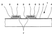
But Fig. 1 shows the schematic plan that has according to the details of the heating plate of electrical terminal connections of the present invention;
But Fig. 2 shows the schematic sectional view that A-A along the line runs through the cross section of the heating plate shown in Fig. 1;
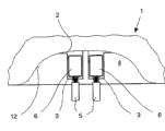
But Fig. 3 shows the schematic plan according to the details of the optional execution mode of heating plate of the present invention, and wherein terminal region is placed on the interior glass pane surface of glass plate of lamination; And
Fig. 4 shows the schematic sectional view by the execution mode shown in Fig. 3.
Embodiment
But Fig. 1 shows the schematically showing of details of the heating plate 1 that is used for motor vehicles.But heating plate 1 can be the glass pane of lamination, especially as windshield, perhaps can be toughness reinforcing glass pane for example, for example especially as side window or rear window.As shown in Figure 1, being arranged on the surface 4 of glass plate is heating element, and this heating element comprises heater 2 and terminal region 3, and wherein a plurality of heaters 2 can be parallel to terminal region 3.Heater 2 and terminal region 3 are formed by the conductive layer that is deposited on the glass pane surface 4.This layer is for example by silk screen printing/sintering processes production.For this reason, having silk screen printing cream between 50 to 80at.% silver content for example is printed onto with the thickness of needs on (through cleaning) plate surface 4.Make typographic metal-containing layer drying (for example in infrared ray or hot air dryer) then.Metal-containing layer is subsequently in 2 to 10 minutes time of the temperature sintering between 600 ℃ to 700 ℃.This heat treatment also can with other combined with heat treatment, for example during glass sheets bending and/or patent.
If the glass of lamination is as glass plate, it comprises two float glass plate that for example connect together, and inserts at least one plastic film of for example being made by PVB between these two float glass plate.Typical windshield comprises the float glass plate of two bendings, and the thickness of glass of the float glass plate that each is crooked is that 1.5-2.1mm and PVB film thickness are 0.76mm.
In a preferred embodiment, the metal derby 6 that is fixed to terminal line 5 ends comprises metal sleeve, and promptly the thickness of being made by copper alloy is the cut cable sleeve pipe of 0.5-1mm, and this sleeve pipe is about 6 * 7mm to form area
2The mode of metal derby 6 that thickness is about the roughly rectangular shape of 1.5mm is crimped onto on the end that exposes of terminal line 5.About 7 * 6mm
2The side be smooth.In addition, the electroplating surfaces with tin of curling metal sleeve.
But Fig. 2 shows the schematic sectional view that A-A along the line runs through the details of the heating plate shown in Fig. 1.Here can see the terminal line 5 that is clipped in the metal sleeve sweep metal-cored 8.Because metal sleeve is crimped onto on metal-cored 8, therefore between metal sleeve and sweep, produce reliable connection of good electricity and machinery.
The curling metal sleeve that forms metal derby 6 with metal-cored 8 of inside is being welded on the terminal region 3 on the bigger area.In order between the terminal region 3 of metal sleeve (cut cable sleeve pipe) and heating element of curling, to produce welding point, use following processes.Manually place the bead of heavily about 0.3g of traditional soldering silk (for example 62%Pb/25%Mn/10%Bi/3%Ag), be about 400 ℃ flatiron by flatiron temperature simultaneously solder flux is added on the metal-containing layer of the terminal region 3 that is printed onto on the glass surface 4.The bead relatively flat of fusing on terminal region 3, and have the diameter of about 6mm.In all cases, the bigger flat contact area 7 of metal sleeve to be fixed is placed on this bead, and utilizes flatiron to exert pressure on the opposing face of metal sleeve, and the bead below being positioned at is owing to the heat by the metal sleeve transmission begins fusing.This manually takes place, and amounts to about 5 to 8 seconds weld time.(oxide is less) surface of the relative cleaning of metal sleeve guarantees the good heat transmission from the flatiron to the metal sleeve and from the metal sleeve to the bead.For above-mentioned reasons, the temperature of flatiron is adjusted into low relatively about 400 ℃.Not only form homeostatic mechanical organ by metal sleeve and metal-cored 8 metal derbies that form 6 that are clipped in wherein, it also provides the higher relatively thermal capacitance with good thermal conductivity characteristic.This helps to alleviate the formation of micro-crack.
Fig. 3 and Fig. 4 show an execution mode, and wherein heater 2 and terminal region 3 are placed on the inner surface 4 of glass plate 10 of glass structure 1 of lamination.In the embodiment of this execution mode, the glass structure 1 of lamination comprises two glass plates 10 and 11 that connect together, and is inserted with at least one plastic film between these two glass plates 10 and 11.In the fringe region that is furnished with terminal region 3 of the glass structure 1 of lamination, glass plate 11 (it is not the carrier of heating element) has recess 12, guarantee and to produce electrical terminal connections freely near the terminal region 3 of another glass plate 10 with permission by this recess 12.In this embodiment, the thickness of the whole assembly of electrical terminal connections is no more than glass plate 11, makes terminal connections can not be projected on the upper side plane of glass plate 11.Consider the thickness of conducting shell of heating element and the thickness of the solder layer 9 between metal derby 6 and the terminal region 3, the thickness that this means metal derby 6 is chosen as and makes the upside of metal derby 6 not be projected on the upside of glass plate 11.
In the scope of inventive concepts, can expect numerous optional execution mode.Glass plate can be the laminated glass of toughness reinforcing safety glass or two or more a plurality of glass plate or plastic plate.The metal-containing layer of heater 2 and terminal region 3 can be deposited on the interior or outer surface 4 of glass plate.In addition, a plurality of plate surface 4 can be provided with heating element.Heating element can be provided with two or more a plurality of terminal region 3.Terminal region 3 can have rectangle or any other shape.A plurality of heaters 2 can be in parallel between every pair of terminal region 3.
Manually do not place bead by means of flatiron, terminal region 3 also can be provided with scolder or tin layer in another way.For example, the tin layer can print, then fusing.The heater layer preferably comprises a high proportion of silver, but also can expect other composition.
Terminal line preferably includes sweep.But also can expect other cable design.Metal derby is preferably produced by metal sleeve is crimped onto on the sweep.But metal sleeve also can be welded on the end of terminal line by means of the scolder of high temperature melting.
Claims (28)
1, a kind of glass plate with at least one electric functional elements,
Wherein said function element comprises that at least one electric conductor (2) and at least one are positioned at the terminal region (3) at the place, end of described electric conductor (2), and wherein said electric conductor (2) and described terminal region (3) are formed by the conductive layer on the surface that is deposited on described glass plate (4);
Wherein, terminal line (5) is connected to described at least one terminal region (3) by welding point,
It is characterized in that,
Described terminal line (5) is fixed to the have flat contact area metal derby (6) of (7), and described flat contact area (7) is welded on the corresponding terminal region (3).
2, glass plate according to claim 1 is characterized in that, described metal derby is resistant to bending metal derby (6).
3, glass plate according to claim 1 and 2 is characterized in that, the size of the described contact zone (7) of described metal derby (6) is at least 10mm
2
4, glass plate according to claim 3 is characterized in that, the full-size of described contact zone (7) is 50mm
2
According to claim 3 or 4 described glass plates, it is characterized in that 5, the contact zone (7) of described metal derby (6) is not more than the terminal region (3) of described function element (2,3).
6, according to each describedly has at least one electric functional elements (2 in the claim 1 to 5,3) glass plate, it is characterized in that described terminal line (5) is guided to metal derby (6) in the plane that is basically parallel to described contact zone (7), and laterally leave described metal derby (6).
7, glass plate according to claim 6 is characterized in that, the end of described terminal line (5) is surrounded by described metal derby (6).
8, according to claim 6 or 7 described glass plates, it is characterized in that, the described contact zone (7) of described metal derby (6) be at least 3mm, preferably be at least 4mm with the rectangular width of longitudinal direction described terminal line (5).
According to each the described glass plate in the claim 6 to 8, it is characterized in that 9, described metal derby (6) has the cross section with the rectangular essentially rectangular of described longitudinal direction of described terminal line (5), the thickness of described metal derby is at least 1mm.
According to each the described glass plate in the claim 6 to 9, it is characterized in that 10, the size of described metal derby (6) on described longitudinal direction amounts to 4mm at least, preferably 5mm at least.
According to each the described glass plate in the claim 1 to 10, it is characterized in that 11, described terminal line (5) comprises a branch of carefully metal-cored (8).
12, according to each the described glass plate in the claim 1 to 11, it is characterized in that described conductive layer is a metal-containing layer.
13, glass plate according to claim 12 is characterized in that, described metal-containing layer comprises the silver of 50at.% at least.
According to each the described glass plate in the claim 1 to 13, it is characterized in that 14, described glass pane surface (4) is the surface of the metallic plate (1) of lamination.
15, glass plate according to claim 14, it is characterized in that, described electric functional elements (2,3) be arranged on the interior glass pane surface (4) of laminated glass pane (1), the metallic plate of described lamination (1) is made of two glass plates (10,11) and at least one plastic film of being arranged between described two glass plates.
16, glass plate according to claim 15, it is characterized in that, be not provided with described function element (2,3) described glass plate (11) is provided with recess (12) at least one terminal region (3) is deposited on zone on another glass plate (10), can arrive described terminal region (3) by described recess (12).
According to claim 15 or 16 described glass plates, it is characterized in that 17, the thickness of the described metal derby (6) in the welding is less than the gross thickness of the glass plate (11) with described recess (12) and described plastic film.
According to each the described glass plate in the claim 1 to 17, it is characterized in that 18, described metal derby (6) is the metal sleeve that is crimped onto on the end of described terminal line (5).
19, glass plate according to claim 18 is characterized in that, the wall thickness of described metal sleeve is 0.5-1mm.
20, glass plate according to claim 19 is characterized in that, described metal sleeve is made by copper alloy, and be curled so that thus the thickness of the metal derby of Xing Chenging (6) between between 1.3mm and the 1.7mm and width between 5 and 6mm between.
According to claim 19 or 20 described glass plates, it is characterized in that 21, the described metal derby (6) that is curled has zinc-plated surface.
According to each the described glass plate in the claim 1 to 21, it is characterized in that 22, described function element (2,3) is a heating element, described electric conductor (2) is a heater, and wherein said heater is provided with at least two terminal region (3).
23, a kind ofly produce electric functional elements (2 on the glass plate, the method of electrical terminal connections 3), wherein, described function element (2,3) have at least one electric conductor (2) and at least one and be positioned at terminal region (3) on the end of described electric conductor (2), described electric conductor (2) and described terminal region (3) are formed by the conductive layer that is deposited on the glass pane surface, said method comprising the steps of:
For each terminal region (3) is provided with at least one terminal line (5);
Counter-bending metal derby (6) with flat contact area (7) is fixed on the end of described terminal line (5);
Scolding tin is deposited on the described contact zone (7) of the terminal region (3) of described function element (2,3) and/or described metal derby (6); And
The described contact zone (7) of described metal derby (6) is placed and is pressed on the described terminal region (3), thereby make described melts soldering tin, allow solder cools then.
24, method according to claim 23, it is characterized in that, described metal derby (6) is fixed to the end of described terminal line (5), and metal sleeve is shifted onto the end of described terminal line (5), and metal sleeve is curled and forms the described metal derby (6) with described flat contact area (7).
25, method according to claim 24 is characterized in that, described metal sleeve is curled so that counter-bending metal derby (6) is formed with minimum 10mm
2And maximum 50mm
2Contact zone (7).
According to claim 24 or 25 described methods, it is characterized in that 26, described metal sleeve is curled so that metal derby (6) is formed with essentially rectangular cross section and the thickness of 1mm at least.
27, according to each the described method in the claim 23 to 26, it is characterized in that, before or afterwards, the surface of described metal derby (6) is zinc-plated in the zone of described contact zone (7) at least at fixing described terminal line (5).
According to each the described method in the claim 23 to 27, it is characterized in that 28, described scolding tin is deposited on the described terminal region (3) of described function element (2,3) by the fusing bead.
Applications Claiming Priority (2)
| Application Number | Priority Date | Filing Date | Title |
|---|---|---|---|
| DE102006017675A DE102006017675A1 (en) | 2006-04-12 | 2006-04-12 | Glass pane with electrical functional element with soldered connection leads and method for making electrical connections |
| DE102006017675.8 | 2006-04-12 |
Publications (1)
| Publication Number | Publication Date |
|---|---|
| CN101454943A true CN101454943A (en) | 2009-06-10 |
Family
ID=38123680
Family Applications (1)
| Application Number | Title | Priority Date | Filing Date |
|---|---|---|---|
| CNA2007800178568A Pending CN101454943A (en) | 2006-04-12 | 2007-04-12 | Glass pane having soldered electrical terminal connections |
Country Status (9)
| Country | Link |
|---|---|
| US (1) | US20090277671A1 (en) |
| EP (1) | EP2011188A1 (en) |
| JP (1) | JP2010500703A (en) |
| KR (1) | KR20090039671A (en) |
| CN (1) | CN101454943A (en) |
| BR (1) | BRPI0710711A2 (en) |
| DE (1) | DE102006017675A1 (en) |
| RU (1) | RU2008144582A (en) |
| WO (1) | WO2007116088A1 (en) |
Cited By (13)
| Publication number | Priority date | Publication date | Assignee | Title |
|---|---|---|---|---|
| CN102549845A (en) * | 2010-01-27 | 2012-07-04 | 矢崎总业株式会社 | Connector |
| CN102972092A (en) * | 2010-07-13 | 2013-03-13 | 法国圣戈班玻璃厂 | Disc comprising an electrical connection element |
| CN103262646A (en) * | 2011-05-10 | 2013-08-21 | 法国圣戈班玻璃厂 | Window panes with electrical connection elements |
| CN105189399A (en) * | 2013-02-05 | 2015-12-23 | 日本板硝子株式会社 | Laminated glass |
| CN107591627A (en) * | 2016-07-08 | 2018-01-16 | 理查德弗里茨控股有限责任公司 | Method for the connection component of conductive contact and for manufacturing such connection component |
| CN108886844A (en) * | 2016-07-27 | 2018-11-23 | 法国圣戈班玻璃厂 | Glass pane equipped with the electric installation with improved welding section |
| CN110191866A (en) * | 2017-01-19 | 2019-08-30 | 日本板硝子株式会社 | Laminated glass |
| CN110626310A (en) * | 2018-06-22 | 2019-12-31 | 长城汽车股份有限公司 | Vehicle window glass assembly, window glass breakage detection system and automobile |
| CN111225833A (en) * | 2018-09-25 | 2020-06-02 | 法国圣戈班玻璃厂 | Parts with electrically functional elements for the manufacture of composite glass panes |
| CN111697352A (en) * | 2019-03-14 | 2020-09-22 | 安塔亚技术公司 | Conductive connector |
| CN111886108A (en) * | 2018-03-22 | 2020-11-03 | 中央硝子株式会社 | Method for producing vehicle glass component |
| CN112690040A (en) * | 2018-09-21 | 2021-04-20 | 纬湃科技有限责任公司 | Contact device and arrangement having a substrate and a contact device arranged thereon |
| CN115594419A (en) * | 2021-07-08 | 2023-01-13 | 福耀玻璃美国股份有限公司(Us) | Ultra-thin laminated glass assembly with electrical circuitry |
Families Citing this family (38)
| Publication number | Priority date | Publication date | Assignee | Title |
|---|---|---|---|---|
| FR2921520B1 (en) | 2007-09-20 | 2014-03-14 | Saint Gobain | ELECTRICAL CONNECTION ELEMENT AND GLAZING PROVIDED WITH SUCH A ELEMENT |
| DE102007059818B3 (en) | 2007-12-11 | 2009-04-09 | Saint-Gobain Sekurit Deutschland Gmbh & Co. Kg | Window pane with a flat electrical connection element |
| DE102008030101A1 (en) | 2007-12-11 | 2009-06-25 | Saint-Gobain Sekurit Deutschland Gmbh & Co. Kg | solder connection |
| DE102008015852A1 (en) * | 2008-03-27 | 2009-10-01 | Rehau Ag + Co. | Heatable plastic pane i.e. panoramic roof, for use as e.g. rear window of motor vehicle, has heating conductor, electric conductor and contact element, where contact element is arranged between electric conductor and heating conductor |
| DE102008015853A1 (en) * | 2008-03-27 | 2009-10-01 | Rehau Ag + Co | Heatable plastic disk i.e. plastic disk laminate, manufacturing method for motor vehicle, involves imprinting heating conductor on plastic layer in silk-screen printing process, where layer is formed as foil or as injection molding part |
| CA2766240A1 (en) * | 2009-06-23 | 2010-12-29 | Toshiba Mitsubishi-Electric Industrial Systems Corporation | Electrode base |
| EP2339894A1 (en) | 2009-12-22 | 2011-06-29 | Saint-Gobain Glass France | Pane with electric connection element |
| EP2365730A1 (en) | 2010-03-02 | 2011-09-14 | Saint-Gobain Glass France | Pane with electric connection element |
| EP2409833A1 (en) * | 2010-07-23 | 2012-01-25 | Saint-Gobain Glass France | Laminated glazing for head-up display |
| JPWO2012118202A1 (en) * | 2011-03-02 | 2014-07-07 | セントラル硝子株式会社 | Terminal structure for glass plate with conductive part and glass plate article using the same |
| MX2013013015A (en) | 2011-05-10 | 2014-01-31 | Saint Gobain | GLASS SHEET THAT INCLUDES AN ELECTRICAL CONNECTION ELEMENT. |
| KR101553762B1 (en) | 2011-05-10 | 2015-09-16 | 쌩-고벵 글래스 프랑스 | Pane having an electrical connection element |
| WO2013128161A1 (en) | 2012-02-29 | 2013-09-06 | Pilkington Group Limited | Bondable electrical connector and method of utilizing same |
| TWM435133U (en) * | 2012-03-16 | 2012-08-01 | Unihan Corp | Insulating device |
| PT2896269T (en) | 2012-09-14 | 2017-06-23 | Saint Gobain | Pane with electric connection element |
| MY170325A (en) | 2012-09-14 | 2019-07-17 | Saint Gobain | Pane with an electrical connection element |
| ES2621224T3 (en) | 2012-11-21 | 2017-07-03 | Saint-Gobain Glass France | Panel with electrical connection element and joint core |
| US10414378B2 (en) * | 2013-07-02 | 2019-09-17 | Pilkington Group Limited | Window assembly |
| DE202014004267U1 (en) * | 2014-05-23 | 2014-07-04 | Few Fahrzeugelektrikwerk Gmbh & Co. Kg | Electrical connection element for fastening, in particular soldering on a glass pane as well as mixed tape braid |
| WO2015196777A1 (en) * | 2014-06-25 | 2015-12-30 | 谢哲澜 | Electrical heating pad for water tank |
| DE102014116283B4 (en) * | 2014-11-07 | 2016-05-19 | Webasto SE | Method for processing a first component and a second component and device |
| WO2016080406A1 (en) | 2014-11-17 | 2016-05-26 | 大日本印刷株式会社 | Heating plate, conductive pattern sheet, vehicle, and method for manufacturing heating plate |
| US10912155B2 (en) | 2014-11-17 | 2021-02-02 | Dai Nippon Printing Co., Ltd. | Heating plate, conductive pattern sheet, vehicle, and method of manufacturing heating plate |
| JP2016102056A (en) * | 2014-11-17 | 2016-06-02 | 大日本印刷株式会社 | Glass laminate and manufacturing method thereof |
| USD815042S1 (en) * | 2015-03-26 | 2018-04-10 | Few Fahrzeugelektrikwerk Gmbh & Co. Kg | Mounting device |
| DE102015119252B4 (en) * | 2015-11-09 | 2024-02-01 | Webasto SE | Device for a heater for a vehicle |
| EP3955704B1 (en) | 2015-11-17 | 2025-07-23 | Dai Nippon Printing Co., Ltd. | Heating electrode device, electrical heating glass, heat-generating plate, vehicle, window for building, sheet with conductor, conductive pattern sheet, conductive heat-generating body, laminated glass, and manufacturing method for conductive heat-generating body |
| JP6922210B2 (en) * | 2016-12-20 | 2021-08-18 | Agc株式会社 | Vehicle window glass |
| USD857420S1 (en) | 2016-12-23 | 2019-08-27 | Few Fahrzeugelektrikwerk Gmbh & Co. Kg | Mounting device |
| DE202016008092U1 (en) | 2016-12-28 | 2017-03-03 | Few Fahrzeugelektrikwerk Gmbh & Co. Kg | Electrical connection element |
| US11490465B2 (en) | 2017-03-02 | 2022-11-01 | Pilkington Group Limited | Window assembly having a terminal connector |
| GB201704525D0 (en) | 2017-03-22 | 2017-05-03 | Central Glass Co Ltd | Vehicle glass window with electrical connector soldered by lead-free solder |
| JP7450843B2 (en) * | 2018-09-07 | 2024-03-18 | セントラル硝子プロダクツ株式会社 | Glass assembly for vehicle windows |
| CN113412173B (en) * | 2019-02-08 | 2023-02-17 | 日本板硝子株式会社 | glass plate assembly |
| JP7028854B2 (en) * | 2019-12-26 | 2022-03-02 | 株式会社オートネットワーク技術研究所 | Wire harness and power storage module |
| US12103366B2 (en) * | 2020-03-31 | 2024-10-01 | Magna Mirrors Of America, Inc. | Vehicular liftgate window assembly with heater grid electrical connection through glass window panel |
| US20210308991A1 (en) * | 2020-04-02 | 2021-10-07 | Pleotint, Llc | Interlayers and laminates incorporating the interlayers |
| CN116762239A (en) * | 2021-02-01 | 2023-09-15 | Agc株式会社 | Window glass for vehicles with metal terminals |
Family Cites Families (18)
| Publication number | Priority date | Publication date | Assignee | Title |
|---|---|---|---|---|
| US2623971A (en) * | 1951-06-21 | 1952-12-30 | Blue Ridge Glass Corp | Electric resistance heater |
| US2644066A (en) * | 1951-07-05 | 1953-06-30 | Blue Ridge Glass Corp | Electrical connector for resistance elements on glass plates |
| US2815497A (en) * | 1953-04-23 | 1957-12-03 | Amp Inc | Connector for aluminum wire |
| US3364460A (en) * | 1964-11-09 | 1968-01-16 | Thomas & Betts Corp | Seamed sleeve connector |
| US4137447A (en) * | 1978-04-28 | 1979-01-30 | Ford Motor Company | Electric heater plate |
| US4946563A (en) * | 1988-12-12 | 1990-08-07 | General Electric Company | Process for manufacturing a selective plated board for surface mount components |
| DE8815848U1 (en) * | 1988-12-21 | 1989-02-09 | Flachglas AG, 90766 Fürth | Device for connecting an electrical cable |
| US5089687A (en) * | 1990-10-02 | 1992-02-18 | Ppg Industries, Inc. | Bus bar jumper for heatable windshield |
| GB9118841D0 (en) * | 1991-09-03 | 1991-10-16 | Raychem Sa Nv | Electrical connector |
| FR2703838B1 (en) * | 1993-04-08 | 1995-06-09 | Saint Gobain Vitrage Int | GLAZING PROVIDED WITH A CONNECTING ELEMENT. |
| US5311405A (en) * | 1993-08-02 | 1994-05-10 | Motorola, Inc. | Method and apparatus for aligning and attaching a surface mount component |
| FR2736791A1 (en) * | 1995-07-13 | 1997-01-17 | Inderflex | Mfg. glass wall with integral resistive heating element |
| US5961737A (en) * | 1996-12-12 | 1999-10-05 | Hughes Electronics Corporation | Welded wire termination device and method for constructing a solar array |
| JP2000299140A (en) * | 1999-04-15 | 2000-10-24 | Yazaki Corp | Connection method and connection structure between wires and connection terminals |
| US6406337B1 (en) * | 2000-09-27 | 2002-06-18 | Antaya Technologies Corporation | Glass mounted electrical terminal |
| CN1620841A (en) * | 2001-12-24 | 2005-05-25 | 法国圣戈班玻璃厂 | Process for the production of multilayer components with transparent surface electrodes and electroluminescent elements |
| DE20203202U1 (en) * | 2001-12-31 | 2002-06-06 | Gilliam, Jakob, Dipl.-Ing., 82402 Seeshaupt | Electrical connection |
| DE10208552B4 (en) * | 2002-02-27 | 2006-03-02 | Saint-Gobain Glass Deutschland Gmbh | Electrically heatable tempered glass pane |
-
2006
- 2006-04-12 DE DE102006017675A patent/DE102006017675A1/en not_active Withdrawn
-
2007
- 2007-04-12 BR BRPI0710711-0A patent/BRPI0710711A2/en not_active IP Right Cessation
- 2007-04-12 JP JP2009504747A patent/JP2010500703A/en not_active Withdrawn
- 2007-04-12 EP EP07728013A patent/EP2011188A1/en not_active Withdrawn
- 2007-04-12 US US12/296,785 patent/US20090277671A1/en not_active Abandoned
- 2007-04-12 CN CNA2007800178568A patent/CN101454943A/en active Pending
- 2007-04-12 RU RU2008144582/09A patent/RU2008144582A/en not_active Application Discontinuation
- 2007-04-12 WO PCT/EP2007/053545 patent/WO2007116088A1/en not_active Ceased
- 2007-04-12 KR KR1020087027212A patent/KR20090039671A/en not_active Withdrawn
Cited By (20)
| Publication number | Priority date | Publication date | Assignee | Title |
|---|---|---|---|---|
| CN102549845A (en) * | 2010-01-27 | 2012-07-04 | 矢崎总业株式会社 | Connector |
| US8851935B2 (en) | 2010-01-27 | 2014-10-07 | Yazaki Corporation | Electrical wire harness connector |
| CN102972092A (en) * | 2010-07-13 | 2013-03-13 | 法国圣戈班玻璃厂 | Disc comprising an electrical connection element |
| CN102972092B (en) * | 2010-07-13 | 2018-03-09 | 法国圣戈班玻璃厂 | Plate with electric connecting element |
| CN103262646A (en) * | 2011-05-10 | 2013-08-21 | 法国圣戈班玻璃厂 | Window panes with electrical connection elements |
| CN103262646B (en) * | 2011-05-10 | 2016-04-27 | 法国圣戈班玻璃厂 | Window panes with electrical connection elements |
| CN105189399A (en) * | 2013-02-05 | 2015-12-23 | 日本板硝子株式会社 | Laminated glass |
| CN105189399B (en) * | 2013-02-05 | 2017-08-15 | 日本板硝子株式会社 | Laminating glass |
| CN107591627A (en) * | 2016-07-08 | 2018-01-16 | 理查德弗里茨控股有限责任公司 | Method for the connection component of conductive contact and for manufacturing such connection component |
| CN108886844A (en) * | 2016-07-27 | 2018-11-23 | 法国圣戈班玻璃厂 | Glass pane equipped with the electric installation with improved welding section |
| CN110191866A (en) * | 2017-01-19 | 2019-08-30 | 日本板硝子株式会社 | Laminated glass |
| CN111886108A (en) * | 2018-03-22 | 2020-11-03 | 中央硝子株式会社 | Method for producing vehicle glass component |
| CN110626310A (en) * | 2018-06-22 | 2019-12-31 | 长城汽车股份有限公司 | Vehicle window glass assembly, window glass breakage detection system and automobile |
| CN112690040A (en) * | 2018-09-21 | 2021-04-20 | 纬湃科技有限责任公司 | Contact device and arrangement having a substrate and a contact device arranged thereon |
| US11996653B2 (en) | 2018-09-21 | 2024-05-28 | Vitesco Technologies GmbH | Contact arrangement and device with a base plate and a contact arrangement arranged thereon |
| CN111225833A (en) * | 2018-09-25 | 2020-06-02 | 法国圣戈班玻璃厂 | Parts with electrically functional elements for the manufacture of composite glass panes |
| US12151454B2 (en) | 2018-09-25 | 2024-11-26 | Saint-Gobain Glass France | Component with electrical functional elements for the production of a laminated sheet |
| CN111225833B (en) * | 2018-09-25 | 2024-12-27 | 法国圣戈班玻璃厂 | Components with electrical functional elements for producing composite glass panes |
| CN111697352A (en) * | 2019-03-14 | 2020-09-22 | 安塔亚技术公司 | Conductive connector |
| CN115594419A (en) * | 2021-07-08 | 2023-01-13 | 福耀玻璃美国股份有限公司(Us) | Ultra-thin laminated glass assembly with electrical circuitry |
Also Published As
| Publication number | Publication date |
|---|---|
| US20090277671A1 (en) | 2009-11-12 |
| JP2010500703A (en) | 2010-01-07 |
| BRPI0710711A2 (en) | 2011-08-16 |
| RU2008144582A (en) | 2010-05-20 |
| EP2011188A1 (en) | 2009-01-07 |
| WO2007116088A1 (en) | 2007-10-18 |
| DE102006017675A1 (en) | 2007-10-18 |
| KR20090039671A (en) | 2009-04-22 |
Similar Documents
| Publication | Publication Date | Title |
|---|---|---|
| CN101454943A (en) | Glass pane having soldered electrical terminal connections | |
| KR100762821B1 (en) | Laminated glazing | |
| KR101285245B1 (en) | Windowpane having an electrical flat connecting element | |
| US20070224842A1 (en) | Electrical Connector For A Window Pane Of A Vehicle | |
| CN111344903B (en) | Glazing assembly for vehicle windows | |
| JP2020186169A (en) | Stacked plate for window and production method of stacked plate for window | |
| JP6576467B2 (en) | Glass plate with electrical connection element and coupling element attached to it | |
| EP3102000B1 (en) | Stacked plate for window and method of manufacturing stacked plate for window | |
| MXPA01005324A (en) | Solderable electrical connection element with a solder deposit. | |
| KR100762823B1 (en) | Solderable electrical connection elements with solder deposits and window panes with the connection elements | |
| JPH1029504A (en) | Electrically heatable windscreen | |
| US12212107B2 (en) | Flat connector for soldering on laminated glass | |
| WO2020050120A1 (en) | Vehicle window glass assembly | |
| JP2012185985A (en) | Electric wire with terminal fitting, and method for manufacturing electric wire with terminal fitting | |
| JP6734915B2 (en) | Electrical connector | |
| WO2013183160A1 (en) | Power line with terminal metal fitting and method for fabrication of power line with terminal metal fitting | |
| WO2022172805A1 (en) | Vehicular windowpane | |
| CN114284770B (en) | Automotive glass heating conductive assembly, automotive glass and manufacturing method thereof | |
| CN221275659U (en) | Glass electrical connection structure | |
| EP3721681B1 (en) | Electrical crimp connector with a shield element |
Legal Events
| Date | Code | Title | Description |
|---|---|---|---|
| C06 | Publication | ||
| PB01 | Publication | ||
| C02 | Deemed withdrawal of patent application after publication (patent law 2001) | ||
| WD01 | Invention patent application deemed withdrawn after publication |