CN101443502B - Nonwoven fabric - Google Patents
Nonwoven fabric Download PDFInfo
- Publication number
- CN101443502B CN101443502B CN2007800173348A CN200780017334A CN101443502B CN 101443502 B CN101443502 B CN 101443502B CN 2007800173348 A CN2007800173348 A CN 2007800173348A CN 200780017334 A CN200780017334 A CN 200780017334A CN 101443502 B CN101443502 B CN 101443502B
- Authority
- CN
- China
- Prior art keywords
- aforementioned
- nonwoven fabric
- fibers
- bondedfibre fabric
- fiber
- Prior art date
- Legal status (The legal status is an assumption and is not a legal conclusion. Google has not performed a legal analysis and makes no representation as to the accuracy of the status listed.)
- Expired - Fee Related
Links
Images




Landscapes
- Nonwoven Fabrics (AREA)
- Absorbent Articles And Supports Therefor (AREA)
Abstract
Description
技术领域 technical field
本发明涉及无纺织物。This invention relates to nonwoven fabrics.
背景技术 Background technique
过去,无纺织物用于纸尿布及卫生巾等卫生用品、擦拭器等清扫用品、口罩等医疗用品等广泛的领域。这样,无纺织物在各种各样的不同的领域使用,但是实际上,在用于各个领域的制品的情况下,有必要以适合于各种制品的用途的性质及结构的方式进行制造。In the past, nonwoven fabrics have been used in a wide range of fields, including hygiene products such as disposable diapers and sanitary napkins, cleaning products such as wipes, and medical products such as masks. In this way, nonwoven fabrics are used in various fields, but actually, when they are used in products in various fields, they must be manufactured with properties and structures suitable for the uses of various products.
无纺织物,例如,通过利用干式法或湿式法等形成纤维层(纤维网),利用化学粘合法或热粘合法等将形成纤维层的纤维彼此结合而形成。在使形成纤维层的纤维结合的工艺中,也存在着包括将多个针反复刺入该纤维层的方法、或喷射水流的方法等从外部向纤维层施加物理的力的方法。The nonwoven fabric is formed, for example, by forming a fiber layer (fibrous web) by a dry method or a wet method, and bonding fibers forming the fiber layer to each other by a chemical bonding method or a thermal bonding method. In the process of bonding the fibers forming the fiber layer, there is also a method of applying physical force to the fiber layer from the outside, including a method of repeatedly piercing the fiber layer with a plurality of needles, or a method of spraying water.
但是,这些方法,终究只是将纤维相互交织,并没有调整纤维层中的纤维的取向或配置、或者纤维层的形状等。即,利用这些方法制造的只不过是简单的片状的无纺织物。However, these methods merely interweave the fibers, and do not adjust the orientation or arrangement of the fibers in the fiber layer, or the shape of the fiber layer. That is, what is produced by these methods is only a simple sheet-shaped nonwoven fabric.
另外,也提出过设置有开口的无纺织物的方案。所述方案揭示了为了在无纺织物上形成开口,将无纺织物夹持在配备有向外侧突出的针等的突起的压模与承接该突起的承接侧支承体之间,通过使突起部分贯通无纺织物,形成立体的开口的方法等(例如,参照特开平6-330443号公报)。In addition, a nonwoven fabric provided with openings has also been proposed. Said proposal discloses that in order to form openings on the nonwoven fabric, the nonwoven fabric is sandwiched between a stamper equipped with protrusions such as needles protruding outward and a receiving side support that receives the protrusions, by making the protrusions A method of forming a three-dimensional opening through a nonwoven fabric (for example, refer to JP-A-6-330443).
发明内容 Contents of the invention
但是,这种无纺织物,通过将构成无纺织物的纤维集合体咬入突起部分与承接侧的支承体之间,形成凹凸或开口。因此,例如,在将位于凸部的壁部分、开口的周缘部分等的纤维压缩,以提高纤维密度,进而加热以便无纺织物化时,有时会造成薄膜化。However, in such a nonwoven fabric, concavo-convex or openings are formed by biting the fiber assembly constituting the nonwoven fabric between the protruding portion and the support on the receiving side. Therefore, for example, when the fibers located in the wall portion of the convex portion, the peripheral portion of the opening, etc. are compressed to increase the fiber density, and then heated to form a nonwoven fabric, film formation may occur.
从而,例如,在将这种无纺织物用于吸收性物品的表面片等的情况下,有时,纤维密度高的凸部或薄膜化的开口边缘变得液体难以透过。这样,在凸部或开口周缘招来大量的液体的情况下,液体滞留在该无纺织物内,会产生弄脏穿用者的皮肤等或者给予穿用者不舒服的感觉的可能性。Therefore, for example, when such a nonwoven fabric is used for a top sheet of an absorbent article, etc., it may become difficult for liquid to permeate through a convex portion with a high fiber density or a thinned opening edge. In this way, when a large amount of liquid is attracted by the convex portion or the periphery of the opening, the liquid may remain in the nonwoven fabric, which may stain the wearer's skin or give the wearer an uncomfortable feeling.
本发明的目的是提供一种无纺织物,在形成有凹凸或开口的无纺织物中,进行调整,使得在凸部或凹部等处液体容易透过。An object of the present invention is to provide a nonwoven fabric in which concavities and convexities or openings are formed, and adjustments are made so that liquid can easily permeate through the convex parts or concave parts.
本发明人等发现,通过从上面侧向利用具有规定的不通气部的通气性支承构件从下面侧支承的纤维网上喷射气体,使构成该纤维网的纤维移动,可以形成开口或凹凸,从而完成了本发明。The inventors of the present invention have found that openings or irregularities can be formed by injecting gas from the upper side to the fiber web supported from the lower side by an air-permeable support member having a predetermined air-impermeable part, thereby moving the fibers constituting the fiber web. the invention.
(1)一种无纺织物,在具有第一纵向方向和第二方向的无纺织物中,包括:多个开口部,所述多个开口部沿着前述第一方向形成;多个连接部,所述多个连接部形成在前述多个开口部中的规定的开口部与和该规定的开口部在前述第一方向上相邻的开口部之间;前述多个连接部中的每一个,在前述第二方向上取向的第二方向取向纤维的含有率比在前述第一方向上取向的第一方向取向纤维的含有率高。(1) A nonwoven fabric having a first longitudinal direction and a second direction, comprising: a plurality of openings formed along the aforementioned first direction; a plurality of connecting parts , the plurality of connection portions are formed between a predetermined opening portion of the plurality of opening portions and an opening portion adjacent to the predetermined opening portion in the first direction; each of the plurality of connection portions The content of second direction oriented fibers oriented in the second direction is higher than the content of first direction oriented fibers oriented in the first direction.
(2)如前述第(1)项中所述的无纺织物,对于前述多个开口部,在所述多个开口部的每一个的周缘上的纤维沿着所述多个开口部的每一个的周缘取向。(2) The nonwoven fabric as described in the aforementioned item (1), with respect to the aforementioned plurality of openings, the fibers on the periphery of each of the plurality of openings run along the length of each of the plurality of openings A perimeter orientation.
(3)如前述第(1)或(2)项中所述的无纺织物,前述多个开口部的每一个呈大致的圆形或者大致的椭圆形。(3) The nonwoven fabric as described in the aforementioned item (1) or (2), wherein each of the plurality of openings has a substantially circular or substantially elliptical shape.
(4)如前述第(1)至(3)中任何一项所述的无纺织物,对于前述多个开口的每一个,前述多个开口部在前述第一方向上的长度为0.1mm至5mm。(4) In the nonwoven fabric described in any one of the aforementioned items (1) to (3), for each of the aforementioned plurality of openings, the length of the aforementioned plurality of openings in the aforementioned first direction is 0.1 mm to 5mm.
(5)如前述第(1)至(4)中任何一项所述的无纺织物,前述多个开口部及前述多个连接部,在该无纺织物的第一面侧,形成沿厚度方向凹入的多个槽部,进一步具有以沿着前述多个槽部中的规定槽部的方式相邻且在前述第一面侧沿厚度方向突出的多个凸状部。(5) The nonwoven fabric as described in any one of the aforementioned items (1) to (4), wherein the plurality of openings and the plurality of connecting portions are formed on the first surface side of the nonwoven fabric along the thickness. The plurality of recessed grooves further includes a plurality of convex portions protruding in the thickness direction on the first surface side adjacent to each other along a predetermined one of the plurality of grooves.
(6)如第(5)项所述的无纺织物,对于前述多个槽部的每一个,该无纺织物的厚度方向的高度,在前述多个凸状部的每一个的前述高度的90%以下。(6) In the nonwoven fabric as described in item (5), the height in the thickness direction of the nonwoven fabric for each of the plurality of grooves is equal to or greater than the height of each of the plurality of convex portions. Below 90%.
(7)如第(5)或(6)项所述的无纺织物,前述多个凸状部中的规定的凸状部,与夹着前述多个槽部中的规定的槽部相邻的凸状部相比,前述高度不同。(7) The nonwoven fabric according to item (5) or (6), wherein a predetermined convex portion among the plurality of convex portions is adjacent to a predetermined groove portion sandwiching a predetermined groove portion among the plurality of groove portions. Compared with the convex part, the aforementioned height is different.
(8)如第(5)至(7)项中任何一项所述的无纺织物,前述多个连接部的每一个,在前述多个槽部的每一个中,进一步沿着该无纺织物中的厚度方向凹入。(8) The nonwoven fabric as described in any one of items (5) to (7), each of the aforementioned plurality of connection portions, in each of the aforementioned plurality of groove portions, further along the nonwoven fabric The thickness direction of the object is concave.
(9)如第(5)至(8)项中任何一项所述的无纺织物,前述多个凸状部的每一个的顶部呈大致的扁平状。(9) The nonwoven fabric according to any one of items (5) to (8), wherein the top of each of the plurality of convex portions is substantially flat.
(10)如第(5)至(9)项中任何一项所述的无纺织物,在作为与形成该无纺织物中的前述多个槽部及前述多个凸状部的面相反侧的面的第二面上,形成向着与前述凸状部的突出方向相反侧突出的多个区域。(10) The nonwoven fabric as described in any one of items (5) to (9), on the side opposite to the surface on which the plurality of grooves and the plurality of protrusions are formed in the nonwoven fabric On the second surface of the first surface, a plurality of regions protruding toward the side opposite to the direction in which the convex portion protrudes are formed.
(11)如第(5)至(10)项中任何一项所述的无纺织物,在前述第一方向上呈波浪状地起伏。(11) The nonwoven fabric as described in any one of items (5) to (10), which undulates in a wave shape in the aforementioned first direction.
(12)如第(5)至(9)项中任何一项所述的无纺织物,该无纺织物中的前述第二面侧是大致平坦的。(12) The nonwoven fabric according to any one of items (5) to (9), wherein the second surface side of the nonwoven fabric is substantially flat.
(13)如第(5)至(12)项中任何一项所述的无纺织物,对于前述多个凸状部的每一个中的多个侧部的每一个,前述第一方向取向纤维的含有率比前述第二方向取向纤维的含有率高。(13) The nonwoven fabric according to any one of items (5) to (12), wherein for each of the plurality of side portions in each of the plurality of convex portions, the aforementioned first direction oriented fibers The content rate of the fiber is higher than the content rate of the aforementioned second direction oriented fibers.
(14)如第(5)至(13)项中任何一项所述的无纺织物,对于前述多个凸状部的每一个,从所述规定的凸状部的前述第一面侧测定的空间面积率比从前述规定的凸状部中的前述第二面侧测定的空间面积率大。(14) In the nonwoven fabric as described in any one of items (5) to (13), for each of the plurality of convex portions, measured from the first surface side of the predetermined convex portion The space area ratio is larger than the space area ratio measured from the second surface side in the predetermined convex portion.
(15)如第(5)至(14)项中任何一项所述的无纺织物,前述多个凸状部的每一个,具有作为夹在前述多个侧部中的区域的多个中央部,对于前述多个中央部的每一个,所述多个中央部的每一个中的纤维密度比前述多个连接部的每一个的纤维密度高,比前述多个侧部的每一个的纤维密度低。(15) The nonwoven fabric according to any one of items (5) to (14), wherein each of the plurality of convex portions has a plurality of central For each of the plurality of central portions, the fiber density in each of the plurality of central portions is higher than the fiber density of each of the aforementioned plurality of connection portions, and is higher than the fiber density of each of the aforementioned plurality of side portions low density.
(16)如第(5)至(15)项中任何一项所述的无纺织物,前述多个凸状部的每一个的纤维密度在0.20g/cm3以下,前述多个连接部的每一个的纤维密度在0.20g/cm3以下。(16) The nonwoven fabric as described in any one of items (5) to (15), wherein the fiber density of each of the plurality of convex portions is 0.20 g/cm 3 or less, and the fiber density of each of the plurality of connecting portions is The fiber density of each is below 0.20 g/cm 3 .
(17)如第(5)至(16)项中任何一项所述的无纺织物,前述多个连接部的每一个,在前述多个连接部的每一个中的单位面积重量比前述多个凸状部的每一个的单位面积重量低。(17) The nonwoven fabric as described in any one of items (5) to (16), wherein each of the aforementioned plurality of connecting parts has a weight per unit area in each of the aforementioned plurality of connecting parts that is larger than the aforementioned Each of the convex portions has a low weight per unit area.
(18)如第(5)至(17)项中任何一项所述的无纺织物,前述多个凸状部的每一个,单位面积重量为15g/m2至250g/m2,(18) The nonwoven fabric according to any one of items (5) to (17), wherein each of the plurality of convex portions has a weight per unit area of 15 g/m 2 to 250 g/m 2 ,
前述多个连接部的每一个,单位面积重量为5g/m2至200g/m2。Each of the aforementioned plurality of connection parts has a weight per unit area of 5 g/m 2 to 200 g/m 2 .
(19)如第(1)至(18)项中任何一项所述的无纺织物,构成该无纺织物的纤维混合有憎水性纤维。(19) The nonwoven fabric as described in any one of items (1) to (18), wherein fibers constituting the nonwoven fabric are mixed with hydrophobic fibers.
发明的效果The effect of the invention
根据本发明,可以提供一种在形成凹凸、开口的无纺织物中,以使在凸部、凹部等处容易透过液体的方式进行调整的无纺织物。According to the present invention, it is possible to provide a nonwoven fabric that is adjusted so that liquid can easily permeate through convex parts, concave parts, etc. in a nonwoven fabric formed with irregularities and openings.
附图说明 Description of drawings
图1A是第一种实施形式的无纺织物的平面图。Fig. 1A is a plan view of a nonwoven fabric of a first embodiment.
图1B是第一种实施形式的无纺织物的底面图。Fig. 1B is a bottom view of the nonwoven fabric of the first embodiment.
图2是图1中的区域Y的放大透视图。FIG. 2 is an enlarged perspective view of a region Y in FIG. 1 .
图3A是将细长状构件等间隔地并列配置在网状支承构件上的支承构件的平面图。3A is a plan view of a support member in which elongated members are arranged side by side on a mesh support member at equal intervals.
图3B是将细长状构件等间隔地并列配置在网状支承构件上的支承构件的透视图。Fig. 3B is a perspective view of a support member in which elongated members are arranged side by side on a mesh support member at equal intervals.
图4A是图3的网状支承构件的平面图。4A is a plan view of the mesh support member of FIG. 3 .
图4B是图3的网状支承构件的透视图。4B is a perspective view of the mesh support member of FIG. 3 .
图5是表示在纤维网被图3的支承构件支承下面侧的状态下,向上面侧喷射气体以制造图1的第一种实施形式的无纺织物的状态的图示。Fig. 5 is a diagram showing a state in which the nonwoven fabric of the first embodiment shown in Fig. 1 is produced by injecting gas toward the upper side with the fiber web being supported on the lower side by the supporting member of Fig. 3 .
图6是说明第一种实施形式的无纺织物制造装置的侧视图。Fig. 6 is a side view illustrating the nonwoven fabric manufacturing apparatus of the first embodiment.
图7是说明图6的无纺织物制造装置的平面图。Fig. 7 is a plan view illustrating the nonwoven fabric manufacturing apparatus of Fig. 6 .
图8是图6中的区域Z的放大透视图。FIG. 8 is an enlarged perspective view of a region Z in FIG. 6 .
图9是图8中的喷出部的底面图。Fig. 9 is a bottom view of the ejection unit in Fig. 8 .
图10A是形成有多个椭圆状的开口的板状支承构件的平面图。10A is a plan view of a plate-shaped support member formed with a plurality of elliptical openings.
图10B是形成有多个椭圆状的开口的板状支承构件的透视图。Fig. 10B is a perspective view of a plate-shaped support member formed with a plurality of elliptical openings.
图11是将金属丝织成螺旋状、在其间隙中形成多个孔部的支承构件的放大平面图及放大透视图。Fig. 11 is an enlarged plan view and an enlarged perspective view of a support member in which wires are helically woven and a plurality of holes are formed in gaps therebetween.
图12是第二种实施形式的无纺织物的放大的透视图。Fig. 12 is an enlarged perspective view of a second embodiment of the nonwoven fabric.
图13是第三种实施形式的无纺织物的放大的透视图。Fig. 13 is an enlarged perspective view of a third embodiment of the nonwoven fabric.
图14是将细长状构件等间隔地并列配置在具有波浪状的起伏的网状支承构件上的支承构件的透视图。Fig. 14 is a perspective view of a support member in which elongated members are arranged side by side at equal intervals on a net-like support member having wave-like undulations.
图15是第四种实施形式的无纺织物的放大透视图。Fig. 15 is an enlarged perspective view of a nonwoven fabric of a fourth embodiment.
图16是第五种实施形式的无纺织物的放大透视图。Fig. 16 is an enlarged perspective view of a nonwoven fabric of a fifth embodiment.
图17是开设有多个椭圆状的开口部的板状支承构件的放大透视图。Fig. 17 is an enlarged perspective view of a plate-shaped support member provided with a plurality of elliptical openings.
图18是表示在纤维网将下面侧支承在图17的板状支承构件上的状态下,向上面侧喷射气体,制造图16所示的第五种实施形式的无纺织物的状态的图示。Fig. 18 is a diagram showing a state in which the nonwoven fabric of the fifth embodiment shown in Fig. 16 is produced by injecting gas toward the upper side with the fiber web supporting the lower side on the plate-shaped supporting member of Fig. 17 .
图19是第六种实施形式的无纺织物的放大透视图。Fig. 19 is an enlarged perspective view of a nonwoven fabric of a sixth embodiment.
图20是将根据本发明的无纺织物用于卫生巾的表面片的情况下的透视图。Fig. 20 is a perspective view of a case where the nonwoven fabric according to the present invention is used for a top sheet of a sanitary napkin.
图21是将根据本发明的无纺织物用于尿布的表面片的情况下的透视图。Fig. 21 is a perspective view of a case where the nonwoven fabric according to the present invention is used for a topsheet of a diaper.
图22是将根据本发明的无纺织物作为吸收性物品的中间片使用的情况下的透视图。Fig. 22 is a perspective view of a case where the nonwoven fabric according to the present invention is used as a middle sheet of an absorbent article.
图23是将根据本发明的无纺织物作为吸收性物品的最外部使用的情况下的透视图。Fig. 23 is a perspective view of a case where the nonwoven fabric according to the present invention is used as the outermost part of an absorbent article.
具体实施方式 Detailed ways
下面,参照附图说明实施本发明的最佳形式。Hereinafter, the best mode for carrying out the present invention will be described with reference to the drawings.
图1A是第一种实施形式的无纺织物的平面图。图1B是第一种实施形式的无纺织物的底面图。图2是图1中的区域Y的放大透视图。图3A是将细长状构件等间隔地并列配置在网状支承构件上的支承构件的平面图。图3B是将细长状构件等间隔地并列配置在网状支承构件上的支承构件的透视图。图4A是图3的网状支承构件的平面图。图4B是图3的网状支承构件的透视图。图5是表示在纤维网被图3的支承构件支承下面侧的状态下,向上面侧喷射气体、制造图1的第一种实施形式的无纺织物的状态的图示。图6是说明第一种实施形式的无纺织物的制造装置的侧视图。图7是说明图6的无纺织物的制造装置的平面图。图8是图6中的区域Z的放大透视图。图9是图8中的喷出部的底面图。图10A是形成多个椭圆状的开口的板状支承构件的平面图。图10B是形成多个椭圆状的开口的板状支承构件的透视图。图11是将金属丝织成螺旋状、在其间隙中形成多个孔部的支承构件的放大平面图及放大透视图。Fig. 1A is a plan view of a nonwoven fabric of a first embodiment. Fig. 1B is a bottom view of the nonwoven fabric of the first embodiment. FIG. 2 is an enlarged perspective view of a region Y in FIG. 1 . 3A is a plan view of a support member in which elongated members are arranged side by side on a mesh support member at equal intervals. Fig. 3B is a perspective view of a support member in which elongated members are arranged side by side on a mesh support member at equal intervals. 4A is a plan view of the mesh support member of FIG. 3 . 4B is a perspective view of the mesh support member of FIG. 3 . Fig. 5 is a view showing a state in which the nonwoven fabric of the first embodiment shown in Fig. 1 is produced by injecting gas toward the upper side while the fiber web is supported on the lower side by the support member shown in Fig. 3 . Fig. 6 is a side view illustrating the nonwoven fabric manufacturing apparatus of the first embodiment. Fig. 7 is a plan view illustrating the nonwoven fabric manufacturing apparatus of Fig. 6 . FIG. 8 is an enlarged perspective view of a region Z in FIG. 6 . Fig. 9 is a bottom view of the ejection unit in Fig. 8 . 10A is a plan view of a plate-shaped support member formed with a plurality of elliptical openings. Fig. 10B is a perspective view of a plate-shaped support member formed with a plurality of elliptical openings. Fig. 11 is an enlarged plan view and an enlarged perspective view of a support member in which wires are helically woven and a plurality of holes are formed in gaps therebetween.
图12是第二种实施形式的无纺织物的放大透视图。图13是第三种实施形式的无纺织物的放大透视图。图14是将细长状构件等间隔地并列配置在具有波浪状的起伏的网状支承构件上的支承构件的透视图。图15是第四种实施形式的无纺织物的放大透视图。图16是第五种实施形式的无纺织物的放大透视图。图17是开设有多个椭圆状的开口部的板状支承构件的放大透视图。图18是表示在纤维网将下面侧支承在图17的板状支承构件上的状态下,在上面侧喷射气体、制造图16所示的第五种实施形式的无纺织物的状态的图示。图19是第六种实施形式的无纺织物的放大透视图。Fig. 12 is an enlarged perspective view of a nonwoven fabric of a second embodiment. Fig. 13 is an enlarged perspective view of a third embodiment of a nonwoven fabric. Fig. 14 is a perspective view of a support member in which elongated members are arranged side by side at equal intervals on a net-like support member having wave-like undulations. Fig. 15 is an enlarged perspective view of a nonwoven fabric of a fourth embodiment. Fig. 16 is an enlarged perspective view of a nonwoven fabric of a fifth embodiment. Fig. 17 is an enlarged perspective view of a plate-shaped support member provided with a plurality of elliptical openings. Fig. 18 is a diagram showing a state in which the nonwoven fabric of the fifth embodiment shown in Fig. 16 is produced by injecting gas on the upper side with the fiber web supporting the lower side on the plate-shaped supporting member of Fig. 17 . Fig. 19 is an enlarged perspective view of a nonwoven fabric of a sixth embodiment.
图20是将根据本发明的无纺织物用于卫生巾的表面片的情况下的透视图。图21是将根据本发明的无纺织物用于尿布的表面片的情况下的透视图。图22是将根据本发明的无纺织物作为吸收性物品的中间片使用的情况下的透视图。图23是将根据本发明的无纺织物作为吸收性物品的最外部使用的情况下的透视图。Fig. 20 is a perspective view of a case where the nonwoven fabric according to the present invention is used for a top sheet of a sanitary napkin. Fig. 21 is a perspective view of a case where the nonwoven fabric according to the present invention is used for a topsheet of a diaper. Fig. 22 is a perspective view of a case where the nonwoven fabric according to the present invention is used as a middle sheet of an absorbent article. Fig. 23 is a perspective view of a case where the nonwoven fabric according to the present invention is used as the outermost part of an absorbent article.
本发明的无纺织物是至少形成有规定的开口部的无纺织物。The nonwoven fabric of the present invention is a nonwoven fabric formed with at least predetermined openings.
第一种实施形式first form of implementation
下面,利用图1至图11说明本发明的无纺织物的第一种实施形式。Next, a first embodiment of the nonwoven fabric of the present invention will be described with reference to FIGS. 1 to 11 .
[1.1]形状[1.1] Shape
如图1A、图1B、图2或者图5所示,根据本实施形式的无纺织物120是形成有多个开口部3的无纺织物。详细地说,无纺织物120是在该无纺织物120的一面侧沿着作为第一方向的长度方向大致等间隔地并列地形成多个槽部1,同时,在该槽部1处形成多个开口部3的无纺织物。所述多个开口部3的每一个形成大致的圆形或者大致的椭圆形。这里,在本实施形式中,槽部1大致等间隔并列地形成,但是,并不局限于此,例如也可以隔开不同的间隔形成,也可以按照槽部1相互之间的间隔变化的方式形成。As shown in FIG. 1A, FIG. 1B, FIG. 2 or FIG. 5, the
另外,在多个槽部1的每一个之间分别形成多个凸状部2。凸状部2与槽部1一样,以大致相等的间隔并列地形成。在本实施形式的无纺织物120中的凸状部2的高度(厚度方向)大致相等,但是,也可以按照使相互邻接的凸状部2的高度不同的方式形成。例如,通过调整喷出主要由气体形成的流体的后面所述的喷出口913的间隔,可以调整凸状部2的高度。例如,通过缩小喷出口913的间隔,可以降低凸状部2的高度,反之,通过扩大喷出口913的间隔,可以增高凸状部2的高度。进而,通过以窄的间隔和宽的间隔交替的方式形成喷出口913的间隔,也可以交替地形成高度不同的凸状部2。另外,这样,如果部分地改变凸状部2的高度,由于和皮肤接触的面积减小,所以,具有可以减轻给予皮肤的负担的优点。In addition, a plurality of
另外,在本实施形式中,无纺织物120中的凸状部2在该无纺织物120中的厚度方向的高度以比槽部1高的方式形成。具体地说,可以列举出为0.3至15mm,优选地为0.5至5mm。另外,凸状部2在作为横向方向的宽度方向上的长度例如可以为0.5至30mm,优选地为1.0至10mm。另外,夹着槽部1邻接的凸状部2相互之间的距离可以列举出为0.5至30mm,优选为3至10mm。In addition, in the present embodiment, the height of the
另外,槽部1在无纺织物120的厚度方向的高度以比凸状部2低的方式形成。具体地说,为凸状部2在厚度方向上的高度的90%以下,优选为1至50%,更优选地为0至20%的高度。这里,厚度方向的高度为0%表示该处是开口部3。Moreover, the height of the
槽部1的宽度方向的长度例如可以是0.1至30mm,优选为0.5至10mm。夹着凸状部2相邻的槽部1相互之间的距离可以是0.5至20mm,优选为3至10mm。The length in the width direction of the
通过这样设计,例如,在使用该无纺织物120作为吸收性物品的表面片的情况下,能够形成适合于即使在将大量的规定的液体排泄出来时在表面上也难以广泛的渗透的槽部1。另外,即使在施加过剩的外部压力时凸状部2变成塌溃的状态,也容易保持由槽部1形成的空间,即使在施加外部压力的状态下排泄规定的液体的情况下,也难以广泛的在表面上渗透。进而,即使在一度吸收到吸收体等中的规定的液体在外部压力下返回来的情况下,由于通过在该无纺织物120的表面上形成凹凸,与皮肤接触的面积少,所以,也难以再次大面积地附着到皮肤上。By designing in this way, for example, when using the
这里,槽部1或者凸状部2的高度、或节距、宽度的测定方法,如下面所述。例如,将无纺织物120在未加压的状态下载置在工作台上,利用显微镜从无纺织物120的截面照片或者截面图像来进行测定。Here, the method of measuring the height, pitch, and width of the
在测定高度(厚度方向的长度)时,从无纺织物120的最下部位置(即工作台表面)到朝向上方的凸状部2及槽部1各自的最高位置作为高度进行测定。When measuring the height (length in the thickness direction), the height is measured from the lowest position of the nonwoven fabric 120 (that is, the table surface) to the highest positions of the
另外,作为凸状部2的节距,测定相互邻接的凸状部2的中心位置相互之间的距离。同样地,作为槽部1的节距,测定相互邻接的槽部1的中心位置相互之间的距离。In addition, the distance between the center positions of the adjacent
在测定凸状部2的宽度时,测定从无纺织物120的最下位置(即,工作台表面)到朝向上方的凸状部2的底面的最大宽度,也以同样的方法测定槽部1。When measuring the width of the
这里,对于凸状部2的截面形状没有特定的限制。例如,可以列举出拱顶状、梯形、三角形、Ω状、四角形等。为了使触及皮肤的感觉良好,凸状部2的顶面附近及侧面优选为曲面。另外,为了即使在外压将凸状部2压溃的情况下,也能够保持由槽部1形成的空间,优选使得从凸状部2的底面到顶面宽度变窄。凸状部2的顶面优选为大致的拱顶状等曲线(曲面)。Here, there is no particular limitation on the cross-sectional shape of the
另外,如图1A、图1B及图2所示,本实施形式的无纺织物120是在槽部1上形成有多个开口部3的无纺织物。所述多个开口部3的每一个的形状形成大致的圆形或者大致椭圆形。并且,在所述多个开口部各自之间以使与该槽部1邻接的凸状部2相互连起来的方式形成连接部4。换句话说,以规定的间隔形成的多个连接部4将凸状部2和与之邻接的凸状部2连接起来。In addition, as shown in FIGS. 1A , 1B and 2 , the
在本实施形式中,以大致相等的间隔形成开口部3,但是,本发明并不局限于此,也可以以不同的间隔形成。In this embodiment, the
每一个开口部3在作为第一方向的长度方向上的长度及作为第二方向的宽度方向的长度可以例如均为0.1至5mm,优选为0.5至4mm。另外,夹着连接部4相互邻接的开口部3的节距可以例如为0.5至30mm,优选为1至10mm。The length of each
连接部4中朝向无纺织物120的厚度方向的高度等于或者小于凸状部2朝向无纺织物120的厚度方向的高度,优选为凸状部2朝向无纺织物120的厚度方向的高度的20%至100%,更优选为40%至70%。The height of the connecting
另外,每一个连接部4在该无纺织物120的长度方向上的长度及在宽度方向上的长度可以例如为0.1至5mm,优选为0.5至4mm。另外,夹着开口部3相互邻接的连接部4的顶点之间的节距可以例如为0.5至30mm,优选为1至10mm。In addition, the length of each connecting
另外,连接部4在该无纺织物的长度方向上的截面形状呈大致的四角形。另外,连接部4的长度方向上的截面形状并不局限于四角形,也可以是拱顶形、梯形、三角形、Ω形等,没有特定的限制。为了抑制在槽部1处的规定的液体的扩大,优选为大致四角形。另外,为了在过剩的外压下连接部4与皮肤等接触不给予人以异物感,该连接部4的顶面优选为平面或者曲面。Moreover, the cross-sectional shape of the
[1.2]纤维取向[1.2] Fiber Orientation
如图2所示,该无纺织物120形成在作为第一方向的长度方向上取向的纵向取向纤维的含有率分别不同的区域。换句话说,形成在作为第二方向的宽度方向上取向的横向取向纤维的含有率分别不同的区域。各个不同的区域,例如,可以列举出槽部1、凸状部2的侧部8、被相邻的侧部8夹着的中央部9等。As shown in FIG. 2 , in this
这里,所谓纤维101在第一方向(纵向方向)取向,指的是纤维101相对于作为第一方向、在这里为经由制造无纺织物的机械将无纺织物或者纤维网送出的方向(MD方向)的规定的纵向方向,在从-45度至+45度的范围内取向,另外,将沿第一方向取向的纤维称为纵向取向纤维。另外,纤维101沿第二方向(无纺织物中的横向方向)的取向,指的是纤维101相对于第二方向、这里为作为与MD方向正交的方向(CD方向)的无纺织物的规定的宽度方向,在从-45度至+45度的范围内取向,另外,将沿第二方向取向的纤维称为横向取向纤维。Here, so-called
侧部8是相当于凸状部2的两侧部的区域,在该侧部8处的纤维101以沿着该凸状部2的长度方向的方向取向的纤维多的方式形成。例如,侧部8处的纤维101与在该凸状部2的中央部9(两侧部8之间的区域)中的纤维101的取向相比,沿长度方向取向的纤维多。例如,在侧部8处的纵向取向的纤维的含有率为55%至100%,更优选为60%至100%。在纵向取向纤维的含有率低于55%的情况下,在制造无纺织物时,通过无纺织物被装置拉拽,该侧部8有时会被拉长。进而,通过侧部8被拉长,当无纺织物被装置拉拽时,有时槽部1或后面所述的中央部9同样会被拉长。The
中央部9是成为凸状部2中的两侧部的侧部8之间的区域,是纵向取向纤维的含有率比侧部8低的区域。该中央部9优选将纵向取向纤维和横向取向纤维适度地混合。The
例如,在中央部9处的纵向取向纤维的含有率比侧部8处的纵向取向纤维的含有率低10%以上,比槽部1的底部11处的纵向取向纤维的含有率高10%以上。具体地说,纵向取向纤维的含有率优选在40%至80%的范围。For example, the content of longitudinally oriented fibers at the
槽部1是在以主要由气体构成的流体(例如热风)被直接喷射的方式形成的同时、形成开口部3及连接部4的区域。当主要由气体构成的流体被喷射时,被主要由气体构成的流体喷射的部分沿厚度方向凹入,同时,在被喷射的部分处,沿长度方向取向的纤维101(纵向取向纤维)被吹到侧部8侧。另外,借助被喷射的主要由气体构成的流体和/或被吹到后面描述的支承构件220的不通气部、其流动方向改变了的主要由气体构成的流体,将沿宽度方向取向的纤维101(横向取向纤维)向连接部4侧喷射。这样,在槽部1的连接部4处的纤维101沿着与该槽部1的长度方向交叉的方向,具体地说,作为整体沿着宽度方向取向。从而,在开口部3的周缘处的纤维101沿着开口形状取向。The
从而,在该无纺织物120中,槽部1的连接部4的纵向取向纤维的含有率最低。换句话说,连接部4横向取向纤维的含有率最高。具体地说,横向取向纤维的含有率为55%至100%,优选为60%至100%。在横向取向纤维的含有率低于55%的情况下,如后面所述,由于槽部1的单位面积重量低,所以,难以提高无纺织物在宽度方向上的强度。这样,例如,在作为吸收性物品的表面片使用该无纺织物120的情况下,在使用该吸收性物品的过程中,由于和身体的摩擦,会在宽度方向上产生经纬滑动,或者产生破损的危险性。Therefore, in this
纤维取向的测定利用株式会社キ—エンス制造的デジタルマイクロスコ—プ(数字显微镜)VHX-100来进行,用下面所述的方法进行。(1)将样品按照其长度方向处于正确的方向的方式置于观察台上。(2)将不规则地出现在近前的纤维除去,使透镜的焦点与样品的最靠近前的纤维重合。(3)设定摄影深度(纵深),在PC的画面上制成样品的3D图像。其次,(4)将3D图像转换成2D图像,(5)在测定范围内,在画面上画出将长度方向恰当地等分的多个平行线。(6)在画出平行线而细分化了的各个单元内,观察纤维取向是第一方向(长度方向)还是第二方向(宽度方向),测定朝向各个方向的纤维条数。然后,(7)通过计算相对于在设定范围内的全部纤维条而言,朝向第一方向(长度方向)的纤维取向的纤维条数的比例,以及朝向第二方向(宽度方向)的纤维取向的纤维条数的比例,进行测定、计算。The measurement of fiber orientation was carried out using Digital Microscope VHX-100 manufactured by Keyence Co., Ltd., by the method described below. (1) Place the sample on the observation table in such a way that its longitudinal direction is in the correct direction. (2) Remove fibers that appear irregularly near the front, and make the focal point of the lens coincide with the fiber closest to the front of the sample. (3) The imaging depth (depth) is set, and a 3D image of the sample is created on the PC screen. Next, (4) convert the 3D image into a 2D image, and (5) draw a plurality of parallel lines on the screen that properly divide the longitudinal direction into equal parts within the measurement range. (6) In each subdivided unit by drawing parallel lines, observe whether the fiber orientation is in the first direction (longitudinal direction) or the second direction (width direction), and measure the number of fibers oriented in each direction. Then, (7) By calculating the ratio of the number of fibers oriented in the first direction (length direction) to all the fiber slivers within the set range, and the number of fibers oriented in the second direction (width direction) The ratio of the number of oriented fibers is measured and calculated.
[1.3]纤维的疏密[1.3] Density of fibers
如图2所示,对凸状部2进行调整,使其平均纤维密度高于槽部1的平均纤维密度。凸状部2的纤维密度可以利用主要由气体构成的流体(例如,热风)的量、张力等各种条件进行任意调整。As shown in FIG. 2 , the
在凸状部2处的纤维密度,例如,可以为0.005至0.20g/cm3,优选为0.007至0.07g/cm3。在该凸状部2的纤维密度低于0.005g/cm3的情况下,不仅由于该凸状部2内含有的液体的自身重量或外部压力,凸状部2容易塌溃,而且,在加压的情况下,一度被吸收的液体有时容易返回。另外,在凸状部2的纤维密度高于0.20g/cm3的情况下,由该凸状部2带来的液体难以向下方移动,液体滞留在该凸状部2处,有时会给予穿用者潮湿的感觉。The fiber density at the
将槽部1调整为平均纤维密度低于凸状部2。该槽部1的整体的平均纤维密度具体地,例如,可以为0.002至0.18g/cm3,优选为0.005至0.05g/cm3。在槽部1的整体平均纤维密度低于0.002g/cm3时,例如,在将该无纺织物120用于吸收性物品等的情况下,有时该无纺织物120容易破损。另外,在槽部1的整体的平均纤维密度高于0.18g/cm3时,由于液体难以向下方移动,所以滞留在该槽部1的底部,有可能给予使用者潮湿的感觉。另外,可以利用主要由气体构成的流体(例如,热风)的量或张力等各种条件任意调整槽部1的底部的平均纤维密度。The
另外,在槽部1处的连接部4的纤维密度例如可以为0.005至0.20g/cm3,优选地为0.007至0.10g/cm3。在连接部4的纤维密度低于0.005g/cm3时,在施加过剩的外部压力、凸状部2塌溃的情况下,该连接部4有时同样会塌溃。In addition, the fiber density of the connecting
另一方面,在连接部4的纤维密度高于0.20g/cm3时,落入槽部1内的规定的液体会滞留在连接部4中,在过剩的外部压力施加到该无纺织物120上、与皮肤直接接触的情况下,会给予潮湿的感觉。On the other hand, when the fiber density of the connecting
另外,该无纺织物120,从作为在该无纺织物120的厚度方向的一面侧的、形成槽部1及凸状部2的面侧测定的空间面积率,比从作为与在该无纺织物120的厚度方向上的形成槽部1及凸状部2的面相反侧的面的另一面侧测定的空间面积率低。In addition, in this
在后面描述的支承构件220上被运送的纤维网100,由于重力,纤维101有向与主要由气体构成的流体喷射的面相反的面侧移动、在靠近该相反侧的面侧的部位处的纤维之间的距离变窄的倾向。另一方面,随着靠近主要由气体构成的流体喷射的面侧,有纤维之间的距离变宽的倾向。In the
进而,通过喷射主要由气体构成的流体,靠近支承构件220侧的纤维101靠在支承构件220上,朝向支承构件220的平面方向。借此,纤维之间的距离进一步变窄,纤维相互之间容易密集。而且,在这种状态下,通过烤炉处理等热处理,纤维相互热粘合,纤维101的自由度变低,无纺织物120中的另一面侧的纤维之间的空间面积率变低。Furthermore, by spraying a fluid mainly composed of gas, the
另一方面,随着从支承构件220侧的面靠近喷射主要由气体构成的流体的面侧,纤维之间不会被过分压溃,另外,在凸状部2处,通过被喷射的主要由气体构成的流体碰到支承构件220并被弹回,纤维101部分地变成相对于该支承构件220垂直取向。在这种状态下,通过将纤维相互热粘合,纤维之间的空间面积率增高。On the other hand, as the surface on the side of the
这里,所谓空间面积率,指的是不存在纤维的空间面积相对于总面积的比例。另外,空间面积率的测定方法如下所述。Here, the "space area ratio" refers to the ratio of the space area where no fibers exist to the total area. In addition, the measuring method of a space area ratio is as follows.
测定设备使用利用株式会社キ—エンス制造的デジタルマイクロスコ—プ(数字显微镜)VHX-100。首先,(1)在观察台上,以沿着槽部1及凸状部2的方向成为纵向方向的方式将样品置于测定设备上,(2)在凸状部2的顶点处,从凸状部2突出的面和与凸状部2突出的面相反侧的面分别进行以下的测定。As a measurement device, Digital Microscope VHX-100 manufactured by Keyence Co., Ltd. was used. First, (1) place the sample on the measurement device so that the direction along the
(3)适当地设定测定设备的透镜的放大率和个人计算机画面上的放大率,将透镜的焦点对准样品的最靠近前侧的纤维(除掉不规则的出现在近前的纤维)。然后,(4)适当地设定摄影深度(纵深),制成样品的3D图像。(3) Appropriately set the magnification of the lens of the measurement device and the magnification of the personal computer screen, and focus the lens on the fiber closest to the front side of the sample (removing irregular fibers that appear near the front). Then, (4) appropriately set the imaging depth (depth), and create a 3D image of the sample.
(5)将3D图像转换成2D图像,将设定的体积平面化,指定在该范围内的纤维之间的空间。进而,(6)对于2D图像进行二进制化(二值化)处理,使纤维存在的部位为白色,纤维不存在的部位为黑色。然后,(7)将颜色反转,使纤维不存在的部位为白色,测定白色化的面积等。(5) Convert the 3D image into a 2D image, planarize the set volume, and specify the space between fibers within the range. Furthermore, (6) perform binarization (binarization) processing on the 2D image, and make the portion where the fiber exists white and the portion where the fiber does not exist black. Then, (7) the color is reversed, the portion where the fiber does not exist is made white, and the whitened area is measured.
这里,在本文献中,放大率为300倍,摄影深度为220μm(每20μm摄影一次,共计摄影11次),进行n=10的测定,取平均值。Here, in this document, the magnification ratio is 300 times, and the imaging depth is 220 μm (11 imaging times in total at every 20 μm), n=10 measurements are performed, and the average value is taken.
另外,按如下方式计算空间面积率。In addition, the space area ratio is calculated as follows.
空间面积率(%)=(空间总面积(mm2)/测定范围的面积(mm2))×100Space area ratio (%)=(total space area (mm 2 )/area of measurement range (mm 2 ))×100
这里,空间总面积可以由(测定时的空间总面积/测定时的放大倍数)算出,另外,测定范围面积可以由(测定时的测定范围的面积/测定时的放大倍数)算出。Here, the total space area can be calculated from (total space area at the time of measurement/magnification at the time of measurement), and the area of the measurement range can be calculated from (area of the measurement range at the time of measurement/magnification at the time of measurement).
由于空间面积率越高,纤维之间的距离越大,相当于无纺织物的表面越粗,所以,纤维容易移动,自由度高。进而,对于通过开口处理等部分地将纤维间的距离扩大的无纺织物,通过提高每一个空间的空间面积,在无纺织物中的整个被主要由气体构成的流体喷射的面上,纤维之间的距离变大。因此,例如,在将该无纺织物用于吸收性物品等情况下,可以整体降低排泄物等规定的液体透过该无纺织物120时的阻力,使液体更容易向吸收体等移动。Since the higher the space area ratio, the larger the distance between the fibers, which corresponds to the thicker the surface of the nonwoven fabric, the fibers move easily and have a high degree of freedom. Furthermore, for the non-woven fabric in which the distance between fibers is partially enlarged by opening treatment, etc., by increasing the space area of each space, the entire surface of the non-woven fabric that is sprayed with a fluid mainly composed of gas can be separated between fibers. The distance between becomes larger. Therefore, for example, when the nonwoven fabric is used in an absorbent article or the like, the resistance when a predetermined liquid such as excrement permeates through the
这里,所谓每个空间的空间面积,指的是纤维不存在的空间的总面积相对于在规定的范围内纤维不存在的空间个数的比例。空间面积可以用下面的计算公式进行计算。Here, the spatial area of each space refers to the ratio of the total area of spaces where fibers do not exist to the number of spaces where fibers do not exist within a predetermined range. The space area can be calculated with the following calculation formula.
空间面积(mm2/个)=(空间总面积(mm2)/空间个数(个))Space area (mm 2 /piece) = (total space area (mm 2 )/number of spaces (piece))
从凸状部2中的该凸状部2突出的一侧的面测定的空间面积率与从和该凸状部2突出的面相反侧的面测定的空间面积率之差例如可以为5%至100%,优选为5%至80%,更优选为15%至40%。The difference between the space area ratio measured from the surface on the protruding side of the
另外,从凸状部2突出的一侧的面测定的空间面积率为50%至100%,优选为50%至90%,更优选为50%至80%。In addition, the space area ratio measured from the protruding side surface of the
进而,从凸状部2突出的一侧的面测定的每一个空间的空间面积例如可以为3000μm2以上,优选为3000至30000μm2,更优选为5000至20000μm2。Furthermore, the space area per space measured from the protruding surface of the
[1.4]单位面积重量[1.4] Weight per unit area
无纺织物120的整体的平均单位面积重量具体例如可以为10至200g/m2,优选为20至100g/m2。例如,在将该无纺织物120例如用于吸收性物品的表面片的情况下,当平均单位面积重量低于10g/m2时,有时在使用过程中容易破损。另外,在该无纺织物120的平均单位面积重量高于200g/m2的情况下,有时难以顺滑地使带来的液体向下方移动。Specifically, the overall average basis weight of the
对凸状部2以与槽部1相比纤维101的单位面积重量高的方式进行调整。这里,凸状部2的中央部9的单位面积重量,例如,可以是15至250g/m2,优选为20至120g/m2。在该中央部9的单位面积重量低于15g/m2的情况下,由于包含在该中央部9内的液体的自身重量或外部压力,中央部9不仅容易被塌溃,而且,有时一度吸收的液体在加压下容易返回。另外,在中央部9的单位面积重量大于250g/m2的情况下,难以使该中央部9带来的液体向下方移动,有时液体滞留在该中央部9,给予使用者以潮湿的感觉。The
进而,对于该凸状部2中的侧部8的单位面积重量,可以借助主要由气体构成的流体(例如,热风)的量或施加到无纺织物上的张力等各种条件任意调整。具体地说,在该侧部8处的单位面积重量例如可以为20至280g/m2,优选为25至150g/m2。在该侧部8的单位面积重量低于20g/m2的情况下,有时,由于横向方向的拉伸力,会将侧部8拉长。另外,在该侧部8处的单位面积重量高于280g/m2的情况下,该侧部8带来的液体难以向下方移动,滞留在侧部8,有可能会给予穿用者潮湿的感觉。Furthermore, the basis weight of the
可以调整槽部1的平均单位面积重量,使得与凸状部2相比,纤维101的平均单位面积重量变小。另外,调整槽部1处的平均单位面积重量,使之比该无纺织物120整体的平均单位面积重量低。例如,在槽部1的底部11处的平均单位面积重量可以为3至150g/m2,优选为5至80g/m2。在该槽部1的底部11处的平均单位面积重量低于3g/m2的情况下,在使用过程中有时容易破损。另外,在该槽部1的底部11处的平均单位面积重量高于150g/m2的情况下,该槽部1带来的液体难以向下方(另一面侧)移动,液体滞留在该槽部1处,有可能会给予穿用者潮湿的感觉。The average basis weight of the
进而,将槽部1整体的平均单位面积重量调整得比凸状部2整体的平均单位面积重量低。具体地说,槽部1整体的平均单位面积重量相对于凸状部2的平均单位面积重量而言在90%以下,优选在3%至90%,特别优选在3%至70%。在槽部1整体的平均单位面积重量相对于凸状部2的平均单位面积重量高于90%的情况下,落入槽部1的液体向无纺织物120的下方(另一面侧)移动时的阻力增高,有时液体会从槽部1溢出。另外,在槽部1的底部的单位面积重量相对于凸状部2的单位面积重量低于3%的情况下,例如,在该无纺织物120用于吸收性物品的表面片的情况下,在吸收性物品使用的过程中,有时表面片容易破损。Furthermore, the average basis weight of the
另外,连接部4的单位面积重量例如可以是5至200g/m2,优选为10至100g/m2。在该连接部4的单位面积重量低于5g/m2的情况下,在施加过剩的外部压力、凸状部1塌溃的情况下,在有的情况下,该连接部4也同样塌溃。在连接部4的单位面积重量高于200g/m2的情况下,有时落入槽部1的规定的液体会滞留在连接部4,在过剩的外部压力施加到该无纺织物120上、直接与皮肤接触的情况下,会给予潮湿的感觉。In addition, the weight per unit area of the connecting
[1.5]其它[1.5] Others
例如,在将本实施形式的无纺织物用于为了将规定的液体吸收或使规定的液体透过的情况下,为了槽部1使液体透过,凸状部2难以3,除液体之外,也可以透过固体。For example, in the case where the nonwoven fabric of this embodiment is used for absorbing or permeating a predetermined liquid, in order for the
由于在槽部1上形成有多个开口部3,所以适合于使液体和固体透过。进而,由于槽部1的底部的纤维101沿宽度方向取向,所以可以防止液体过分向槽部1的长度方向流动变宽。虽然槽部1的单位面积重量低,但是,由于使纤维101在该槽部1的宽度方向取向(CD取向),所以,无纺织物的宽度方向上的强度(CD强度)增高。Since a plurality of
虽然将凸状部2的单位面积重量调整得较高,但是,由于纤维条数增大,所以粘合的点数增加,保持多孔结构。Although the weight per unit area of the
在凸状部2中,以支承凸状部2的中央部9的方式,形成将单位面积重量和纤维密度调整得比中央部9高的侧部8。即,侧部8,由于纤维101的大部分沿着长度方向取向,所以,纤维之间的距离变短,从而,纤维密度增高,刚性也变高。从而,由该侧部8保持凸状部2全体,可以防止凸状部2由于外部压力等而塌溃。In the
另外,在槽部1中,每单位面积的横向取向纤维的含有率比中央部9高,在侧部8,每单位面积的纵向取向纤维的含有率比中央部9高。而且,在中央部9,比槽部1或侧部8处含有更多的沿厚度方向取向的纤维101。从而,在中央部9,例如,即使由于施加厚度方向的负荷,凸状部2的厚度减少,在将负荷释放的情况下,通过沿该厚度方向取向的纤维101的刚性,也容易恢复到原来的高度。即,是一种压缩恢复性高的无纺织物。In addition, in the
[1.6]制造方法[1.6] Manufacturing method
下面借助图6至图11,说明制造本实施形式的无纺织物120的方法。首先,将纤维网100载置到作为通气性支承构件的支承构件220的上面侧。换句话说,利用支承构件220从下侧支承纤维网100。Next, a method for producing the
然后,使处于支承该纤维网100的状态的支承构件220沿规定方向移动,通过从该移动的纤维网100的上表面侧连续地喷射气体,可以制造本实施形式的无纺织物120。Then, the
如图6、图7所示,制造本实施形式的无纺织物120的无纺织物制造装置90包括:通气性支承构件200,该通气性支承构件200从下方侧(另一面侧)支承作为纤维集合体的纤维网100;作为喷射机构的喷出部910及图中未示出的送气部,所述喷射机构从作为该纤维集合体的纤维网100中的上方侧(一面侧)向由通气性支承构件200从下方侧(另一面侧)支承的作为纤维集合体的纤维网100喷射主要由气体构成的流体;作为移动机构的输送器930,所述移动机构使作为纤维集合体的纤维网100向规定方向F移动。As shown in Fig. 6 and Fig. 7, the non-woven
通气性支承构件200例如是包括以下部分的支承构件:通气部,所述通气部可以将从纤维网100中的上面侧喷射的主要由气体构成的流体向作为与配置了通气性支承构件200中的纤维网100的一侧相反的一侧的下侧通气;以及不通气部,所述不通气部从纤维网100中的上面侧喷射的主要由气体构成的流体不能向通气性支承构件200中的下侧通气,并且,构成纤维网100的纤维101不能向通气性支承构件200中的相反侧移动。The air-
作为在本实施形式中使用的通气性支承构件200,例如,如图3所示,可以列举出不通气部以规定的图样配置在规定的网状构件上的构件,或者,如图10所示,在不通气性的板状构件上形成有多个规定孔部的构件等。As the air-permeable supporting
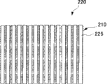
作为将不通气部以规定的图样配置在该规定的网状构件上的构件,例如,可以列举出如图4所示的在网状支承构件210的一个面上等间隔并列地配置作为不通气部的细长状构件225的支承构件220(图3)。这里,作为另外的实施形式,也可以列举出适当地变更作为不通气部的细长状构件225的形状或配置的构件。不通气部,除图3所示的将细长状构件225配置在网状支承构件210的一个面上情况之外,也可以通过填埋(例如,利用软焊料,树脂等)作为通气部的网状孔来形成。As a member for disposing the air-impermeable parts in a predetermined pattern on the predetermined mesh member, for example, as shown in FIG. The
作为在该不通气性板状构件上形成多个规定的孔部的构件,例如,可以列举出图10所示的形成多个作为通气部的椭圆状的孔部233的板状支承构件230。这里,作为另外一种实施形式,可以列举出适当地调整孔部233的形状、大小及配置的方式。例如,通过适当调整作为不通气部的板部235的形状等,可以作为另外一种实施形式。As a member in which a plurality of predetermined holes are formed in the air-impermeable plate-shaped member, for example, a plate-shaped
这里,在成为通气部的区域中的通气度,例如,可以为10000至60000cc/cm2·min,优选为20000至50000cc/cm2·min。但是,在通气性支承构件中,例如,在挖通金属板等形成通气部的情况下,由于不存在主要由气体构成的流体向该板部分的阻力,所以,存在达到上面记载的上述数值以上的通气度的情况。Here, the air permeability in the region serving as the air vent can be, for example, 10000 to 60000 cc/cm 2 ·min, preferably 20000 to 50000 cc/cm 2 ·min. However, in the air-permeable supporting member, for example, in the case of digging through a metal plate to form a vent portion, since there is no resistance of the fluid mainly composed of gas to the plate portion, there is a problem of reaching the above-mentioned numerical value or more described above. airflow situation.
在无纺织物制造装置90中,一面将纤维网100从规定的方向依次移动一面形成无纺织物120。该移动机构借助上述通气性支承构件200使处于被从一个面侧支承的状态下的作为纤维集合体的纤维网100向规定的方向移动。具体地说,使处于被喷射主要由气体构成的流体的状态下的纤维网100向规定方向F移动。作为移动机构,例如,可以列举出图6所示的输送器930。输送器930包括:通气性的通气性带部939,所述通气性带部形成载置通气性支承构件200的横向长的环状;旋转部931、933,所述旋转部位于形成横向长的环状的通气性带部939的内侧、配置在长度方向的两端、使该环状的通气性带部939沿规定的方向旋转。In the nonwoven
如上所述,输送器930使处于从下面侧支承纤维网100的状态下的通气性支承构件200沿规定方向F移动。具体地说,如图6所示,使纤维网100以通过喷出部910的下侧的方式移动。进而,使纤维网100以通过作为加热机构的两侧面开口的加热器部950的内部的方式移动。As described above, the
如图8所示,喷射机构包括图中未示出的送气部及喷出部910。图中未示出的送气部经由送气管920连接到喷出部910上。送气管920能够通气地连接到喷出部910的上侧。如图9所示,在喷出部910上以规定的间隔形成多个喷出口913。As shown in FIG. 8 , the spray mechanism includes an air supply unit and a
从图中未示出的送气部经由送气管920被送气到喷出部910的气体,从形成在喷出部910上的多个喷出口913喷出。从多个喷出口913喷出的气体连续地喷射到被从下面侧支承在通气性支承构件200上的纤维网100的上面侧。具体地说,从多个喷出口913喷出口的气体连续地喷射到处于被输送器930向规定的方向F移动的状态下的纤维网100的上面侧。The gas fed from a gas supply unit (not shown) to the
在喷出部910的下方、配置在通气性支承构件200的下侧的吸气部915对从喷出部910喷出、通过通气性支承构件200的气体等吸气。这里,通过该吸气部915的吸气,能够以贴紧到通气性支承构件200上的方式将纤维网100定位。进而,通过吸气,可以进一步保持在由空气流成形的槽部(凹凸)等形状的状态下,在加热器部950内进行输送。另外,通过该吸气部915吸引(吸气)被喷射的主要由气体构成的流体,可以防止碰到通气性支承构件200的主要由气体构成的流体过剩弹回,防止纤维网100的形状紊乱。The
由吸气部915进行的吸引,其强度达到将主要由气体构成的流体喷射的区域的纤维101被压到通气性支承构件200上的程度即可。The strength of the suction by the
另外,通过调整喷射的主要由气体构成的流体的风量、温度、引入量、支承构件的通气性、纤维网100的单位面积重量等,可以使凸状部2、开口部3及连接部4等的形状发生变化。例如,在使喷射的主要由气体构成的流体的量和吸引(吸气)的主要由气体构成的流体的量几乎均等、或者吸引(吸气)的主要由气体构成的流体的量多的情况下,无纺织物120中的凸状部2的背面侧以沿着通气性支承构件200的形状的方式形成。从而,在通气性支承构件200的形状是平坦的情况下,该无纺织物120的背面侧成为大致平坦的。In addition, by adjusting the air volume, temperature, introduction amount, air permeability of the support member, and the weight per unit area of the
进而,通过从通气性支承构件200的下侧引入主要由气体构成的流体,由于喷射主要由气体构成的流体的区域的纤维一面被推压到该通气性支承构件200侧一面移动,所以,纤维集中在支承构件侧。另外,在凸状部2处,通过被喷射的主要由气体构成的流体碰撞通气性支承构件200,适当地弹回,变成纤维部分地朝向厚度方向的状态。Furthermore, by introducing the fluid mainly composed of gas from the lower side of the air-permeable supporting
虽然从各个喷出口913喷出的主要由气体构成的流体的温度也可以是常温的,但是,例如,为了使槽部(凹凸)、开口部的成形性良好,可以将该温度调整到构成纤维集合体的至少热塑性纤维的软化点以上,优选地,调整到熔点的+50℃至-50℃的温度的范围内。当纤维软化时,由于纤维本身的反弹力变低,所以,容易利用空气流等保持纤维被再排列的形状,当进一步提高温度时,由于纤维彼此的热粘合开始,所以,能够更容易地保持槽部(凹凸)等的形状。从而,在保持槽部(凹凸)等的形状的状态下,易于输送到加热器950内。Although the temperature of the fluid mainly composed of gas ejected from each ejection port 913 may be normal temperature, for example, in order to improve the formability of grooves (concaves and convexes) and openings, the temperature may be adjusted to the temperature of the constituent fibers. The aggregate is at least above the softening point of the thermoplastic fibers, preferably within a temperature range of +50°C to -50°C of the melting point. When the fiber is softened, since the rebound force of the fiber itself becomes low, it is easy to maintain the shape of the rearranged fiber by air flow, etc. When the temperature is further increased, since the thermal bonding of the fibers begins, it can be more easily Holds the shape of grooves (concavities and convexities), etc. Therefore, it is easy to transport into the
作为加热机构的加热器部950,在规定方向F上的两端开口。从而,载置在被输送器930移动的通气性支承构件200上的纤维网100(无纺织物120)以规定的滞留时间连续地在形成于加热器部950内部的加热空间中移动。例如,在构成纤维网100(无纺织物120)的纤维101中含有热塑性纤维的情况下,可以获得通过在该加热器部950中加热使纤维101相互结合的无纺织物115。The
根据制造的无纺织物,可以适当地更换通气性支承构件200。例如,在制造本实施形式的无纺织物120的情况下,作为通气性支承构件200,可以使用支承构件220。The air-permeable supporting
在制造本实施形式的无纺织物120时,在使用图3所示的支承构件220的情况下,在上面侧载置有纤维网100的支承构件220沿着与细长状构件225的长度方向大致正交的方向移动。借此,在纤维网100的上面侧,沿着与形成细长状构件225大致正交的方向连续地喷射气体。即,槽部1沿着与细长状构件225大致正交的方向形成。并且,后面描述的开口部3形成在细长状构件225与槽部1交叉的位置。When manufacturing the
如上所述,细长状构件225是不通气性的构件,例如,从上侧喷射的气体不能向下方侧通气。换句话说,被喷射到细长状构件225的气体改变其流动方向。As described above, the
另外,细长状构件225不使纤维网100中的纤维101向支承构件220的下方侧移动。In addition, the
因此,构成纤维网100的纤维101的移动,借助从纤维网100的上面侧喷射的气体、和/或作为被喷射了的气体在透过纤维网100的同时、由细长状构件225改变了流动方向的气体来进行。Therefore, the movement of the
例如,在喷射了气体的区域中的纤维101被移动到与该区域邻接的区域。并且,由于被喷射气体的区域沿着规定的方向移动,所以,结果,在沿着气体喷射的规定方向连续的区域中的侧方的区域内移动。For example, the
从而,在形成槽部1的同时,以在槽部1中的底部11的纤维101沿着宽度方向取向的方式移动。另外,在槽部1与槽部1之间形成凸状部2,在该凸状部2中的侧方部的纤维密度变高,纤维101沿着长度方向取向等。Thus, while the
进而,作为被喷射的气体,在对纤维网100通气的同时被细长状构件225改变了流动方向的气体,使构成纤维网100的纤维101向与上述不同的方向移动。Furthermore, as the injected gas, the gas whose flow direction is changed by the
由于构成支承构件220的网状支承构件210及细长状构件225限制纤维101向支承构件220的下面侧移动,所以,纤维101在沿着支承构件220的上面的方向上移动。Since the
详细地说,被喷射到细长状构件225上的气体沿着该细长状构件225的方向改变流动。这样改变流动的气体,使配置在细长状构件225的上面的纤维101从细长状构件225的上面向周围区域移动。从而,形成规定形状的开口部3。另外,调整纤维101的取向、疏密或者单位面积重量中的一或两项以上。In detail, the gas injected onto the
另外,为了形成具有开口部3的无纺织物120,也可以使用和上述支承构件220不同的支承构件。利用所使用的支承构件,能够改变槽部1、凸状部2、开口部3及连接部4的大小或排列等。例如,可以使用图11所示的支承构件270。Moreover, in order to form the
支承构件270,例如,可以是相对于大致平行地排列的规定粗度的金属丝271、将其它规定粗度的金属丝272以与多个金属丝271相互桥接的方式交替地卷绕成螺旋状地形成的螺旋编织的通气性网。The supporting
在该支承构件270中的金属丝271及金属丝27成为不通气部。另外,被该支承构件270中的金属丝271及金属丝272包围的部分变成作为通气部的孔部273。The
在这种支承构件的情况下,通过使织入的方法或丝的粗度、丝的形状部分地发生变化,可以部分地使通气度发生变化。例如,可以使用金属丝271为不锈钢的圆形丝、金属丝272为不锈钢的扁平丝、进行螺旋编织而成的支承构件270。In the case of such a support member, the air permeability can be partially changed by partially changing the weaving method, the thickness of the threads, or the shape of the threads. For example, the
但是,在这种情况下的成为不通气部的金属丝271及金属丝272(特别是金属丝的交点部分)的通气度,可以列举为相对于在作为通气部的孔部273处的通气度在90%以下,优选为0%至50%,更优选为0%至20%。在这里,所谓的0%指的是,实质上主要由气体构成的流体是不通气的。However, in this case, the air permeability of the
在使用支承构件270的情况下,例如,当主要由气体构成的流体喷射到支承构件270处的金属丝271与金属丝272的交点部分上时,该主要由气体构成的流体被该交点部分改变其流动方向。从而,将支承在该交点部分的纤维101向前后左右喷射,形成开口部3。In the case of using the
并且,在槽部1中的被交点部分之外支承的区域或者位于孔部273的上面的区域,在被限制向下方的移动的同时,纵向取向纤维向凸状部2中的侧部8移动。进而,通过使由支承构件270的交点部分形成的、横向取向纤维被从开口部3移动,形成连接部4。In addition, in the region supported by the
这里,通过调整向纤维网100喷射的主要由气体构成的流体的温度、量或者强度,另外,调整移动机构中的纤维网100的移动速度、调整张力等,即使用同一个支承构件,也可以制造开口部3、槽部1、凸状部2的形态、单位面积重量、纤维密度不同的无纺织物。另外,通过调整喷射到纤维网100上的主要由气体构成的流体的温度、量或强度,另外,调整移动机构中的纤维网100的移动速度、调整张力等,即使利用不同的支承构件,也可以制造开口部3、槽部1、凸状部2的形态、单位面积重量、纤维密度相同的无纺织物。Here, by adjusting the temperature, amount or strength of the fluid mainly composed of gas sprayed to the
其它实施形式Other forms of implementation
下面,对于本发明的无纺织物中的另外一种实施形式进行说明。另外,在下面的实施形式中,没有特别说明的部分与第一种实施形式一样,在附图中的标号也与第一种实施形式同样的情况下,赋予相同的标号。Next, another embodiment of the nonwoven fabric of the present invention will be described. In addition, in the following embodiments, parts not particularly described are the same as those of the first embodiment, and when the reference numerals in the drawings are also the same as those of the first embodiment, the same reference numerals are assigned.
下面借助图12至图19说明根据本发明的无纺织物的第二种实施形式至第六种实施形式。第二种实施形式是与形成凸状部的面相反侧的面不同的形态的实施形式。第三种实施形式是无纺织物整体的形状不同的实施形式。第四种实施形式是无纺织物的凸状部不同的实施形式。第五种实施形式是槽部不同的实施形式。第六种实施形式是开口部不同的实施形式。A second to a sixth embodiment of the nonwoven fabric according to the invention will be described below with reference to FIGS. 12 to 19 . The second embodiment is an embodiment in which the surface on the opposite side to the surface on which the convex portion is formed is different. A third embodiment is an embodiment in which the shape of the nonwoven as a whole is different. A fourth embodiment is a different embodiment of the convexity of the nonwoven. The fifth embodiment is a different embodiment of the groove. The sixth embodiment is an embodiment in which the opening is different.
[2.1]第二种实施形式[2.1] The second implementation form
下面利用图12说明本发明的无纺织物的第二种实施形式。A second embodiment of the nonwoven according to the invention will be described below using FIG. 12 .
如图12所示,本实施形式的无纺织物172,在该无纺织物172中与形成有槽部1及凸状部2的面相反侧的面的形态不同于第一种实施形式。下面以和第一种实施形式的不同点为中心进行说明。As shown in FIG. 12 , the
[2.1.1]无纺织物[2.1.1] Non-woven fabric
本实施形式的无纺织物172在其一面侧交替地并列形成槽部1及凸状部2。并且,在无纺织物172的另一面侧,位于凸状部2的底面的区域以向该凸状部2突出的一侧突出的方式形成。换句话说,无纺织物172在该无纺织物172的另一面侧中,位于一面侧中的凸状部2的底面上的区域凹入,形成凹部。并且,位于一面侧的槽部1处的底面上的另一面侧的区域向与一面侧的凸状部2相反的方向突出,形成凸状部。In the
[2.1.2]制造方法[2.1.2] Manufacturing method
除上面所述之外,本实施形式的无纺织物172的制造方法与上述第一种实施形式所述的方法相同。另外,在制造该无纺织物172时使用的支承构件,可以使用在上述第一种实施形式中的支承构件220或者支承构件270。Except for the above, the method of manufacturing the
对于该无纺织物172,在将纤维集合体利用支承构件220或者支承构件270从其下面侧支承的状态下,喷射主要由气体构成的流体,同时,从支承构件220或者支承构件270的下方,吸引(吸气)喷射的主要由气体构成的流体。并且,通过使被吸引(吸气)的主要由气体构成的流体的量小于被喷射的主要由气体构成的流体的量,在被喷射的主要由气体构成的流体比被吸引(吸气)的主要由气体构成的流体的量大的情况下,通过使被喷射的主要由气体构成的流体稍稍弹回,能够以和凸状部2的上面侧中向着与凸状部2相同的方向突出的方式形成凸状部2的下面侧(底面侧)。借此,位于槽部1中的底面上的另一面侧的区域相对地突出,形成从下面侧突出的凸状部。For this
[2.2]第三种实施形式[2.2] The third implementation form
下面,利用图13及图14说明本发明的无纺织物的第三种实施形式。Next, a third embodiment of the nonwoven fabric of the present invention will be described with reference to Figs. 13 and 14 .
[2.2.1]无纺织物[2.2.1] Non-woven fabric
如图13所示,本实施形式的无纺织物174,在该无纺织物174整体呈波浪状起伏这一点上与第一种实施形式不同。下面,以和第一种实施形式的不同点为中心进行说明。As shown in FIG. 13, the nonwoven fabric 174 of this embodiment differs from the 1st embodiment in that the whole nonwoven fabric 174 undulates like a wave. The following description will focus on the differences from the first embodiment.
本实施形式的无纺织物174,以该无纺织物174整体具有相对于槽部1及凸状部2延伸的方向大致正交的波浪状起伏的方式形成。The nonwoven fabric 174 of the present embodiment is formed so that the entire nonwoven fabric 174 has undulations substantially perpendicular to the directions in which the
[2.2.2]制造方法[2.2.2] Manufacturing method
对于制造本实施形式的无纺织物174的方法,与第一种实施形式一样,但是,作为通气性支承构件的支承构件280的形态不同。本实施形式的支承构件280,如图14所示,是一种在网状支承构件260的上面以规定的间隔大致平行地配置多个细长状构件285的支承构件。The method of manufacturing the nonwoven fabric 174 of this embodiment is the same as that of the first embodiment, but the form of the
本实施形式的支承构件280,如图14所示,是一种在支承构件280的长的方向或者短的方向中的任何一个方向上,沿平行方向具有波浪状起伏的支承构件。构成该支承构件280的网状支承构件260,如上所述,形成多个孔径小的孔部263,从纤维网100的上面侧喷射的气体不受该网状支承构件260的妨碍地向下方通气。该网状支承构件260不会对喷射的主要由气体构成的流体的流动引起大的变化,另外,不使纤维网101向该网状支承构件260的下方移动。The supporting
而且,配置在构成支承构件280的网状支承构件260的上面的细长状构件285是不使从上面喷射的主要由气体构成的流体向下方通气的不通气部。另外,使从上面喷射的主要由气体构成的流体的流动方向变更。借此,喷射到细长状构件285上的主要由气体构成的流体和/或喷射到该细长状构件285上、其流动方向被改变的主要由气体构成的流体使纤维101移动,形成开口部3。Further, the
进而,由于构成该支承构件280的网状支承构件260本身具有起伏,所以,借助从纤维网100的上面侧喷射的主要由气体构成的流体,纤维网100成形为具有沿着该支承构件280的形状的起伏的形状。Furthermore, since the
在本实施形式中,通过一面向载置在支承构件280的上面的纤维网100喷射主要由气体构成的流体,一面使该纤维网100沿着轴X方向移动,可以形成本实施形式的该无纺织物174。In this embodiment, the
可以任意设定支承构件280中的起伏的形态。例如,如图14所示的向轴X方向的起伏的顶部之间的节距可以是1至30mm,优选为3至10mm。另外,该支承构件280上的起伏的顶部与底部的高低差,例如,可以为0.5至20mm,优选为3至10mm。进而,在该支承构件280中X方向上的截面形状并不局限于图14所示的波浪状,例如,也可以是起伏的各个顶点形成锐角的大致三角形连起来的形状,或者,以起伏的各个顶点大致平坦的方式将大致四角形状的凹凸连起来的形状等。The form of undulations in the
本实施形式的无纺织物174可以利用上述无纺织物制造装置90进行制造。关于该无纺织物制造装置90的无纺织物174的制造方法等,可以参考第一种实施形式的无纺织物120的制造方法及无纺织物制造装置90的说明中记载的内容。The nonwoven fabric 174 of this embodiment can be produced using the nonwoven
[2.3]第四种实施形式[2.3] The fourth implementation form
下面利用图15说明本发明的无纺织物的第四种实施形式。A fourth embodiment of the nonwoven according to the invention will be described below using FIG. 15 .
如图15所示,本实施形式的无纺织物176与第一种实施形式的不同点在于,形成第二凸状部22,该第二凸状部22与在该无纺织物176的一面侧形成的凸状部2在厚度方向上的高度不同。下面,以和第一种实施形式不同的点为中心进行说明。As shown in FIG. 15 , the difference between the
[2.3.1]无纺织物[2.3.1] Non-woven fabric
这是一种在该无纺织物176的一面侧并列地形成多个槽部1的无纺织物。而且,在多个槽部1的各个之间分别交替地形成多个凸状部2及多个第二凸状部22。所述凸状部2及第二凸状部22与槽部1同样地并列地形成。另外,在槽部1上形成开口部3和连接部4。This is a nonwoven fabric in which a plurality of
凸状部2及第二凸状部22是纤维网100上的不被主要由气体构成的流体喷射的区域,通过形成槽部1,成为相对地突出的区域。第二凸状部22,例如,与凸状部2相比,在该无纺织物176的厚度方向上的高度低,在宽度方向上的长度也窄,但是,对于该第二凸状部22上的纤维的疏密、纤维取向及单位面积重量等,与凸状部2相同。The
无纺织物176上的凸状部2及第二凸状部22,在并列地形成的多个槽部1的各个之间形成凸状部2或第二凸状部22。并且,凸状部2以夹着槽部1与第二凸状部22相邻的方式形成。另外,第二凸状部22以夹着槽部1与凸状部2相邻的方式形成。即,凸状部2和第二凸状部22夹着槽部1交替地形成。具体地说,以凸状部2、槽部1、第二凸状部22、槽部1、凸状部2的顺序重复这种配置图形而形成。另外,凸状部2及第二凸状部22的位置关系并不局限于此,可以按照至少无纺织物176的一部分夹着槽部1、多个凸状部2分别相邻的方式形成。另外,多个第二凸状部22也可以以夹着槽部1分别相邻的方式形成。The
[2.3.2]制造方法[2.3.2] Manufacturing method
本实施形式的无纺织物176的制造方法,其用于无纺织物176的制造的无纺织物制造装置90的喷出口913的形态与第一种实施形式的喷出口913不同。The manufacturing method of the
例如,该无纺织物176可以利用调整了喷出主要由气体构成的流体的喷出口913的间隔的无纺织物制造装置90进行制造。例如,通过使喷出口913的间隔比第一种实施形式的喷出口913的间隔窄,可以形成厚度方向的高度比凸状部2低的第二凸状部22。另外,通过使喷出口913的间隔比第一种实施形式的喷出口913的间隔宽,也可以形成宽度方向的长度比凸状部2大的凸状部。另外,在形成喷出口913的间隔中,通过窄的间隔和宽的间隔交替地配置,形成凸状部2和第二凸状部22夹着槽部1交替地并列配置的无纺织物176。For example, this
本实施形式的无纺织物176,如上所述,可以利用无纺织物制造装置90制造,但是,对于在这种无纺织物制造装置90中的无纺织物176的制造方法中的其它内容,可以参考第一种实施形式的无纺织物120的制造方法及无纺织物制造装置90的说明。The
[2.4]第五种实施形式[2.4] The fifth implementation form
下面,利用图16至图18,对于本发明的第五种实施形式进行说明。本发明的无纺织物的第五种实施形式与第一种实施形式的不同点在于,连接部4在厚度方向上凹入。下面,以和第一种实施形式不同点为中心进行说明。Next, a fifth embodiment of the present invention will be described using FIGS. 16 to 18 . The fifth embodiment of the nonwoven according to the invention differs from the first embodiment in that the connecting
[2.4.1]无纺织物[2.4.1] Non-woven fabric
如图16至图18所示,本实施形式的无纺织物178在一面侧形成有槽部1及凸状部2。并且,在槽部1处以规定的间隔形成多个开口部3。As shown in FIGS. 16 to 18 , the
在槽部1的开口部3与邻接的开口部3之间,形成沿无纺织物178的厚度方向凹入的多个凹部44。该凹部44的底部形成在比槽部1的厚度方向的高度低的位置。Between the
在凹部44的底部中的纤维取向,横向取向纤维的含有率比纵向取向纤维的含有率高。即,构成该凹部44的底部的纤维主要以在与该槽部1延伸的方向大致正交的方向(横向方向)上取向的方式形成。In the fiber orientation in the bottom of the
开口部3,在槽部1处,通过凹部44的底部在该无纺织物178的厚度方向上凹入,形成在该槽部1的凹部44之外的部位相对地突出的突出部40。The bottom of the
另外,在该突出部40处,在该开口部3周缘处的纤维101沿着该开口部3的周缘取向。这样,被喷射的主要由气体构成的流体和/或通过喷射到后面描述的板状支承构件290的板部295上、流动方向变更的主要由气体构成的流体,使纤维101沿着开口部3的周缘移动。In addition, at the
槽部1处的凹部44及突出部40的大小等可以适时设定。例如,突出部40与邻接的突出部40在长度方向上的节距可以为1至30mm,优选为3至10mm。另外,凹部44与突出部40的高低差例如可以为0.5至20mm,优选为3至10mm。The size and the like of the recessed
另外,突出部40的平均单位面积重量例如可以为5至200g/m2,优选为10至100g/m2。另外,该突出部40的平均纤维密度例如可以在0.20g/cm3以下,优选为0.005至0.05g/cm3,更优选为0.007至0.10g/cm3。In addition, the average weight per unit area of the protruding
在突出部40的平均单位面积重量低于5g/m2的情况下,或者在平均纤维密度低于0.005g/cm3的情况下,在施加过剩的外部压力凸状部2塌溃的情况下,存在该突出部40也同样塌溃、在槽部1处不能保持由凹部44形成的空间的情况。When the average weight per unit area of the protruding
另一方面,在突出部40的平均单位面积重量高于200g/cm2的情况下,或者平均纤维密度高于0.20g/cm2的情况下,有时落入槽部1内的规定的液体会滞留在突出部40处,在过剩的外部压力施加到该无纺织物178上而与皮肤直接接触的情况下,会给予潮湿的感觉。On the other hand, when the average basis weight of the protruding
另外,凹部44的单位面积重量例如可以是0至100g/m2,优选为0至50g/m2。另外,该凹部44的纤维密度例如可以在0.20g/cm3以下,优选为0.0至0.10g/cm3 In addition, the weight per unit area of the
在凹部44的单位面积重量高于100g/m2的情况下,或者在纤维密度高于0.20g/cm3的情况下,落入槽部1内的规定的液体会一度滞留在凹部44内。具体地说,在将该无纺织物178作为吸收性物品的表面片使用的情况下,若在规定的液体滞留在凹部44内的状态下发生行动变化等,规定的液体容易从凹部44溢出,扩展到槽部1内,进而扩展到无纺织物178的表面上,有时会脏污皮肤。When the weight per unit area of the recessed
[2.4.2]制造方法及支承构件[2.4.2] Manufacturing method and supporting member
对本实施形式的无纺织物178的制造方法,与上面所述一样,但是,通气性支承构件不同。The method of manufacturing the
为了制造该无纺织物178,可以对载置在板状支承构件290的上面的纤维网100,一边从纤维网100的上面侧以比第一种实施形式中喷射主要由气体构成的流体的强度更强的强度喷射主要由气体构成的流体,一边使之沿着Z方向移动来进行制造。In order to manufacture this
板部295使喷射的主要由气体构成的流体不向下方移动。并且,被喷射到该板部295的上侧的纤维网100上的主要由气体构成的流体,其流动方向被改变。例如,通过喷射主要由气体构成的流体形成槽部1。这时,被喷射到板状构件290的板部295上的气体不能向下方通气,其流动方向被改变。The
另外,被喷射的主要由气体构成的流体和/或通过被喷射到板部295上、其流动方向被改变的主要由气体构成的流体使纤维101向周围的区域移动。详细地说,槽部1上的纵向取向纤维被吹到凸状部2侧,槽部1中的横向取向纤维在沿着槽部1的长度方向的方向上被向着前后喷吹。借此,形成开口部3。In addition, the sprayed fluid mainly composed of gas and/or the flow direction of the fluid mainly composed of gas which is sprayed onto the
另外,如图18所示,在主要由气体构成的流体被喷射到板状支承构件290的孔部293上的情况下,沿着该孔部293的内侧面变形,形成凹部44。In addition, as shown in FIG. 18 , when the fluid mainly composed of gas is sprayed onto the
在凹部44处,由于该凹部44处的纵向取向纤维被大量地吹到凸状部2侧,所以,在该凹部44中留下横向取向纤维。从而,凹部44作为一个整体沿着大致与该槽部1正交的方向取向。In the
另外,在板状支承构件290的下侧,例如,也可以配备有网状支承构件210等。通过配备网状支承构件210,可以大致平坦地形成面对凹部44的支承构件的一侧。In addition, on the lower side of the plate-
另外,通过改变该板状支承构件290的厚度或主要由气体构成的流体的量或强度也可以形成上述第一种实施形式的无纺织物120。另外,进而,还可以形成使凹部44从孔部293向板状支承构件290的下方呈突起状(Ω状)突出的无纺织物。为了形成使凹部44向板状支承构件290的下方呈突起状突出的无纺织物,例如,可以列举出以下情况:在主要由气体构成的流体被强力地喷射的情况或被喷射的主要由气体构成的流体的量多的情况,在纤维网100上几乎不施加线性张力的情况,或者在即将对纤维网100喷射主要由气体构成的流体之前,稍稍进行超前进给的情况等。在这样情况下,纤维101容易进入孔部293。In addition, the
本实施形式的板状支承构件290,如图17所示,是形成有多个孔部293的板状的构件。详细地说,由作为不通气部的板部295和作为通气部的孔部293形成。The plate-shaped
通过该板状支承构件290具有规定的厚度,槽部1处的纤维101进入孔部293,形成凹部44,可以在突出部40的下方设置空间。借此,例如,在将高粘度的液体带到该无纺织物178内的情况下,在该空间内可以容纳规定量的高粘度液体。When the plate-shaped
板状支承构件290的厚度,在形成本实施形式的无纺织物178的情况下,例如,可以为0.5至20mm,优选为1.0至5.0mm。另外,在形成第一种实施形式的无纺织物120的情况下,例如可以为0.01至20mm,优选为0.1至5mm。进而,为了形成在板状支承构件290的下方使凹部44呈突起状突出的无纺织物,例如可以是0.5至20mm,优选为1.0至10mm。另外,对于任何一种板状支承构件290,在该板状支承构件290的厚度在20mm以上时的情况下,由于进入板状支承构件290的多个孔部293内的纤维难以从孔部293脱离,所以,有时生产率会恶化。The thickness of the plate-shaped
[2.5]第六种实施形式[2.5] The sixth implementation form
下面利用图19说明本发明的无纺织物的第六种实施形式。A sixth embodiment of the nonwoven fabric according to the invention will be described below using FIG. 19 .
如图19所示,本实施形式的无纺织物160是一种形成有多个开口部3的无纺织物。在不形成凸状部及槽部这一点上与第一种实施形式不同。下面,以和第一种实施形式不同的点为中心进行说明。As shown in FIG. 19, the nonwoven fabric 160 of this embodiment is a nonwoven fabric in which a plurality of
[2.5.1]无纺织物[2.5.1] Non-woven fabric
如图19所示,本实施形式的无纺织物160是形成有多个开口部3的无纺织物。As shown in FIG. 19 , the nonwoven fabric 160 of this embodiment is a nonwoven fabric in which a plurality of
在作为纤维集合体的纤维网100上,例如,沿着作为主要由气体构成的流体喷射的方向的长度方向大致等间隔地形成多个开口部3。另外,在纤维网100的宽度方向的间隔也大致等间隔地形成多个开口部3。这里,开口部3形成的间隔并不局限于此,例如,也可以以不同的间隔形成。In the
所述多个开口部3的每一个形成大致圆形或者大致椭圆形。并且,在多个开口部3的每一个处的纤维取向以沿着开口部3的周围的方式取向。换句话说,在开口部3处的长度方向的端部沿着相对于该长度方向交叉的方向取向,另外,在开口部3的长度方向的侧部,沿着该长度方向取向。Each of the plurality of
另外,由于在所述多个开口部3处的周围的纤维101被喷射的主要由气体构成的流体向该开口部3的周围移动,所以,将该开口部3的周围的纤维密度调整成高于除开口部3的周围之外的区域中的纤维密度。In addition, since the fluid mainly composed of gas injected into the
而且,在该无纺织物160的厚度方向上,载置在支承构件220(图3)上的面(下方)侧的纤维密度形成得比与载置的面相反一侧的面(上面)侧的纤维密度高。这是由于因重力或者喷射的主要由气体构成的流体将纤维网100上的具有自由度的纤维101集中到支承构件220侧而造成的。And, in the thickness direction of this nonwoven fabric 160, the fiber density on the surface (lower) side placed on the support member 220 (FIG. 3) is formed to be higher than that on the surface (upper) side opposite to the surface on which it is placed. The fiber density is high. This is because the
[2.5.2]制造方法[2.5.2] Manufacturing method
本实施形式的制造方法等和上述第一种实施形式的制造方法相同,但是,在该无纺织物160上不形成槽部及凸状部,在这一点上是不同的。下面,以不同点为中心进行说明。The manufacturing method of this embodiment is the same as the manufacturing method of the above-mentioned first embodiment, but it is different in that the non-woven fabric 160 is not formed with grooves and protrusions. Hereinafter, the difference will be mainly explained.
用于形成图19所示的无纺织物160的通气性支承构件,例如,可以列举出图3所示的支承构件220,图18所示的板状支承构件290或者没有通气部的板状的板等。The air-permeable supporting member used to form the nonwoven fabric 160 shown in FIG. 19, for example, can enumerate the supporting
在使用支承构件220或板状支承构件290的情况下,例如,将纤维网101载置到支承构件上,使处于支承纤维网100的状态下的该支承构件沿规定的方向移动,从被移动的纤维网100的上面侧以不形成槽部的程度连续地喷射主要由气体构成的流体。In the case of using the
具体地说,利用喷射的主要由气体构成的流体、和/或作为被喷射的主要由气体构成的流体、在对纤维网100通气的同时被细长状构件225改变流动方向的主要由气体构成的流体,只形成开口部3。Specifically, using the injected fluid mainly composed of gas, and/or as the injected fluid mainly composed of gas, the
另外,被喷射到该无纺织物160上的主要由气体构成的流体的量,只要是使得位于以不形成槽部1的程度喷射的主要由气体构成的流体的区域中的纤维网100的纤维101能够移动的程度即可。在这种情况下,也可以借助引入到支承构件220的下侧的吸气部915对被喷射的主要由气体构成的流体不进行吸引(吸气)。为了不会由于喷射的主要由气体构成的流体弹回到支承构件220而扰乱成形的纤维网100的形状,也可以从支承构件220的下方吸引(吸气)流体。在进行吸引(吸气)的情况下,对主要由气体构成的流体进行吸引(吸气)的量优选为纤维网100不被压在(塌溃在)支承构件220上的程度的量。In addition, the amount of the fluid mainly composed of gas sprayed onto the nonwoven fabric 160 is such that the fibers of the
另外,在使用没有通气部的板状的板等的情况下,将纤维网100载置到该板上,通过一边使处于支承纤维网100的状态下的该支承构件沿规定的方向移动,一边间歇地喷射主要由气体构成的流体,可以制造该无纺织物160。由于该板状的板整个变成不通气部,所以,被间歇地喷射的主要由气体构成的流体与其流动方向改变的主要由气体构成的流体一起形成开口部3。换句话说,在喷射主要由气体构成的流体的部分形成开口部3。In addition, in the case of using a plate-like plate without a vent portion, the
另外,在喷射主要由气体构成的流体、形成具有凹凸的无纺织物之后,也可以卷绕到滚筒等上,将形成的凹凸压溃。另外,也可以将纤维网100预先用加热炉等加热,在将纤维101在一定程度上粘合的状态下喷射主要由气体构成的流体。In addition, after spraying a fluid mainly composed of gas to form a nonwoven fabric having irregularities, it may be wound on a roll or the like to crush the formed irregularities. Alternatively, the
实施例Example
13.1]第一个实施例13.1] First embodiment
<纤维结构><fibrous structure>
使用具有高密度聚乙烯和聚对苯二甲酸乙酯的芯鞘结构、平均纤度为3.3dtex、平均纤维长度51mm、涂布亲水油剂的纤维A和与纤维A在涂布憎水性油剂这一点上不同的纤维B的混棉。使用纤维A和纤维B的混合比为70:30,单位面积重量被调整到40g/m2的纤维集合体。Fiber A with a core-sheath structure of high-density polyethylene and polyethylene terephthalate, an average fineness of 3.3 dtex, an average fiber length of 51 mm, and a hydrophobic oil agent coated with fiber A Blending of different fiber B in this point. The mixing ratio of fiber A and fiber B is 70:30, and the fiber aggregate whose basis weight is adjusted to 40 g/m 2 is used.
<制造条件><Manufacturing conditions>
以直径为1.0mm、节距为6.0mm形成多个图9所示的喷出口913。另外,喷出口913的形状为圆形,喷出口913的截面形状为圆筒形。喷出口913的宽度为500mm。在温度105℃、风量为10001/分钟的条件下,喷射热风。A plurality of ejection ports 913 shown in FIG. 9 are formed with a diameter of 1.0 mm and a pitch of 6.0 mm. In addition, the shape of the discharge port 913 is circular, and the cross-sectional shape of the discharge port 913 is cylindrical. The width of the ejection port 913 was 500 mm. Hot air was sprayed under the conditions of a temperature of 105°C and an air volume of 10,001/min.
支承体使用长度2mm、宽度70mm的拐角形成圆形的横向方向长的形状的挖通的不锈钢类的套筒。在该套筒上,在MD方向(长度方向:槽部或者凸状部延伸的方向)隔开3mm的间隔、在CD方向(短的方向:与槽部或者凸状部延伸的方向大致正交的方向)隔开3mm的间隔,将上述挖通的图形配置成网格状。另外,套筒的厚度为0.5mm。As the support body, a dug-through stainless steel-based sleeve having a circular shape with corners of 2 mm in length and 70 mm in width formed in the horizontal direction was used. On this sleeve, there is an interval of 3 mm in the MD direction (longitudinal direction: the direction in which the grooves or convex parts extend), and in the CD direction (short direction: the direction in which the grooves or convex parts extend) direction) at an interval of 3 mm, and the above-mentioned digging patterns are arranged in a grid pattern. In addition, the thickness of the sleeve is 0.5mm.
将前面所述的纤维结构的纤维用速度为20m/分钟的梳理机开纤,制成纤维网,以450mm的宽度裁断纤维网。然后,以3m/分钟的速度利用20目的通气性网输送纤维网。利用前面所述的喷出部910及喷出口913的设计,在温度105℃、风量12001/分钟的条件下,喷射空气流。然后,从通气性网的下方以小于热风量的吸收量进行吸引(吸气)。之后,在利用通气性网输送该纤维网的状态下,在设定成温度125℃、热风量10Hz的炉子内输送约30秒钟。The fibers of the aforementioned fiber structure were opened with a carding machine at a speed of 20 m/min to form a fiber web, and the fiber web was cut with a width of 450 mm. Then, the fiber web was conveyed by a 20-mesh air-permeable net at a speed of 3 m/min. Using the above-mentioned design of the
<结果><result>
凸状部:单位面积重量为51g/m2,厚度方向的长度为3.4mm(顶部的厚度2.3mm),纤维密度为0.03g/cm3,该凸状部的每一个的宽度为4.6mm,节距为6.7mm。Convex portion: the weight per unit area is 51g/m 2 , the length in the thickness direction is 3.4mm (the thickness of the top is 2.3mm), the fiber density is 0.03g/cm 3 , and the width of each convex portion is 4.6mm, The pitch is 6.7mm.
槽部:单位面积重量为9g/m2,厚度方向的长度为1.8mm,纤维密度为0.005g/cm3,该槽部的每一个的宽度为2.1mm,节距为6.7mm。Grooves: Weight per unit area is 9g/m 2 , length in thickness direction is 1.8mm, fiber density is 0.005g/cm 3 , each groove has a width of 2.1mm and a pitch of 6.7mm.
连接部:单位面积重量为18g/m2,厚度方向的长度为1.8mm,纤维密度为0.01g/cm3,该连接部的每一个的宽度为2.1mm,突出部的每一个的长度为1.5mm,MD方向的节距为5.0mm,CD方向的节距为6.7mm。Connecting part: the weight per unit area is 18g/ m2 , the length in the thickness direction is 1.8mm, the fiber density is 0.01g/ cm3 , the width of each connecting part is 2.1mm, and the length of each protruding part is 1.5mm. mm, the pitch in the MD direction is 5.0mm, and the pitch in the CD direction is 6.7mm.
开口部:该开口部的每一个的宽度为2.1mm,开口部的每一个的长度为3.5mm,MD方向的节距为5.0mm,CD方向的节距为6.7mm。Openings: the width of each opening is 2.1 mm, the length of each opening is 3.5 mm, the pitch in the MD direction is 5.0 mm, and the pitch in the CD direction is 6.7 mm.
形状:分别形成凸状部、槽部、开口部及连接部,凸状部的背面向与凸状部相同的方向隆起,成为不形成该无纺织物的最里面的形状。另外,在槽部,沿着该槽部延伸的方向,交替地形成多个连接部和开口部。该开口部的面积为5.2mm2的纵向长的长方形形状,拐角呈圆形。Shape: a convex portion, a groove portion, an opening, and a connection portion are respectively formed, the back of the convex portion rises in the same direction as the convex portion, and the innermost shape of the nonwoven fabric is not formed. In addition, in the groove portion, a plurality of connection portions and opening portions are alternately formed along the direction in which the groove portion extends. The opening has an area of 5.2 mm 2 in a vertically long rectangular shape with rounded corners.
[3.2]第二个实施例[3.2] The second embodiment
<纤维结构><fibrous structure>
纤维结构和第一个实施例一样。The fiber structure is the same as in the first embodiment.
<制造条件><Manufacturing conditions>
利用前面所述的喷出部910及喷出口913的设计,以温度105℃、风量10001/分钟的条件喷射空气流。然后,从通气性网的下方以与喷射的空气流几乎相等或多一些的吸收量对前面所述的纤维结构的纤维网进行吸引(吸气)。Using the above-mentioned design of the
<结果><result>
凸状部:单位面积重量为49g/m2,厚度方向的长度为3.5mm,纤维密度为0.02g/cm3,该凸状部的每一个的宽度为4.7mm,节距为6.5mm。Convex part: the weight per unit area is 49g/ m2 , the length in the thickness direction is 3.5mm, the fiber density is 0.02g/ cm3 , the width of each protruding part is 4.7mm, and the pitch is 6.5mm.
槽部:单位面积重量为12g/m2,厚度方向的长度为1.9mm,纤维密度为0.006g/cm3,该槽部的每一个的宽度为1.8mm,节距为6.5mm。Grooves: Weight per unit area is 12 g/m 2 , length in thickness direction is 1.9 mm, fiber density is 0.006 g/cm 3 , each groove has a width of 1.8 mm and a pitch of 6.5 mm.
连接部:单位面积重量为23g/m2,厚度方向的长度为1.9mm,纤维密度为0.01g/cm3,该连接部的每一个的宽度为1.8mm,突出部的每一个的长度为1.5mm,MD方向的节距为5.0mm,CD方向的节距为6.5mm。Connecting part: the weight per unit area is 23g/ m2 , the length in the thickness direction is 1.9mm, the fiber density is 0.01g/ cm3 , the width of each connecting part is 1.8mm, and the length of each protruding part is 1.5mm. mm, the pitch in the MD direction is 5.0mm, and the pitch in the CD direction is 6.5mm.
开口部:该开口部的每一个的宽度为1.8mm,开口部的每一个的长度为3.2mm,MD方向的节距为5.0mm,CD方向的节距为6.5mm。Openings: the width of each opening is 1.8 mm, the length of each opening is 3.2 mm, the pitch in the MD direction is 5.0 mm, and the pitch in the CD direction is 6.5 mm.
形状:分别形成凸状部、槽部、开口部及连接部,凸状部的背面大致是平坦的。另外,在槽部,沿着该槽部延伸的方向交替地形成多个连接部和开口部。该开口部的面积为4.2mm2的纵向长的长方形形状,拐角呈圆形的形状。Shape: a convex part, a groove part, an opening part and a connection part are respectively formed, and the back surface of the convex part is substantially flat. In addition, in the groove portion, a plurality of connection portions and opening portions are alternately formed along the direction in which the groove portion extends. The opening has a vertically long rectangular shape with an area of 4.2 mm 2 , and its corners are rounded.
用途例Application example
作为本发明中的无纺织物的用途,例如,可以列举出卫生巾、衬里、尿布等的吸收性物品中的表面片等。在这种情况下,凸状部可以是皮肤面侧、背面侧中的任何一个,但是,通过将凸状部形成在皮肤面侧,由于可以降低与皮肤接触的面积,所以不容易给予由体液引起的潮湿感。另外,也可以作为吸收性物品的表面片与吸收体之间的中间片使用。由于与表面片或者吸收体的接触面积减小,所以存在不容易从吸收体返回的情况。另外,由于与皮肤的接触面积减小或具有缓冲感,所以,也可以在吸收性物品的侧片或尿布等的外表面(最外部)、面扣件(面フアスナ—)的阴扣件等中使用。另外,也可以用于除去附着在床或身体上的尘埃或污垢等的擦拭器、口罩、母乳垫等多个方面。Examples of uses of the nonwoven fabric in the present invention include topsheets in absorbent articles such as sanitary napkins, liners, and diapers. In this case, the convex part may be on the skin side or the back side, but by forming the convex part on the skin side, since the area in contact with the skin can be reduced, it is not easy to administer the drug caused by body fluids. caused by dampness. Moreover, it can also be used as an intermediate sheet|seat between the top sheet of an absorbent article, and an absorber. Since the contact area with the surface sheet or the absorber decreases, it may not be easy to return from the absorber. In addition, since the contact area with the skin is reduced or has a cushioning feeling, it can also be used on the side panels of absorbent articles or the outer surface (outermost) of diapers, female fasteners of surface fasteners, etc. used in . In addition, it can also be used in various fields such as wipers for removing dust and dirt adhering to the bed or body, masks, and breast milk pads.
[4.1]吸收性物品的表面片[4.1] Top sheet of absorbent article
作为本发明的无纺织物的用途,如图20、21所示,例如,可以列举出将具有凹凸、在凹部设置有多个开口部3和与凸状部2相比纤维密度相对较低的连接部的无纺织物作为吸收性物品的表面片301、302使用的情况。在这种情况下,优选地,以形成有凸状部2的面成为皮肤侧的方式配置该无纺织物。As the use of the nonwoven fabric of the present invention, as shown in FIGS. 20 and 21 , for example, non-woven fabrics having irregularities, a plurality of
在将该无纺织物作为吸收性物品的表面片301、302使用的情况下,当规定的液体被排泄时,该液体主要落入槽部中。另外,由于设置有开口部3,所以,例如,即使是含有固体成分的具有粘性的液体,借助开口部3容易向吸收体移动,可以抑制液体在表面上大范围地扩展。When the nonwoven fabric is used as the
另外,由于连接部4相对而言比凸状部2的纤维密度低,所以,被排泄到连接部4的液体也可以迅速地向吸收体移动。Moreover, since the fiber density of the
进而,由于在连接部4处的纤维的大部分沿着宽度方向取向,所以,向宽度方向的抗拉强度高,在吸收性物品的穿用过程中,可以防止施加朝向宽度方向的摩擦等的力而使该表面片301、302破损。Furthermore, since most of the fibers at the connecting
另一方面,凸状部2的侧部8,由于纤维相互密集,所以刚性高。而且,由于沿长度方向取向的纵向取向纤维的含有率高,所以即使负荷施加到凸状部2上,也易于防止塌溃,例如,即使凸状部2被负荷压溃,压缩恢复性也会很高。On the other hand, the
从而,即使由于身体的姿势变化,施加到表片301、302上的负荷变化,也可以保持与皮肤接触的面积较低,所以,可以维持触感,进而,即使一度被吸收体吸收的液体返回,也难以再次大面积的附着到皮肤上。Thereby, even if the load applied to the
[4.2]吸收性物品的中间片[4.2] Middle sheet of absorbent article
作为本发明的无纺织物的用途,如图22所示,例如,可以列举出将具有凹凸、在凹部设置有多个开口部3和与凸状部2相比纤维密度相对低的连接部4的该无纺织物作为吸收性物品的中间片311使用的情况。在这种情况下,优选地,以形成有凸状部2的面成为表面片310侧的方式配置该无纺织物。As the use of the nonwoven fabric of the present invention, as shown in FIG. 22 , for example, there are concavities and convexities, a plurality of
通过以形成凸状部2的面成为表面片310侧的方式将该无纺织物作为中间片311配置,可以在表面片310与中间片311之间设置多个空间。进而,通过在中间片311上设置开口部3,在短时间排泄大量的液体的情况下,妨碍液体透过的因素少,可以迅速地使该液体向吸收体移动。并且,可以防止该液体大范围地在表面片310上扩展。By arranging this nonwoven fabric as the
进而,即使一度透过中间片311被吸收体吸收的液体返回,由于中间片311与表面片310的接触率低,所以该液体难以返回表面片310再次大面积地附着在皮肤上。Furthermore, even if the liquid absorbed by the absorber once passed through the
另外,由于中间片311中的凸状部的中央部9与侧部8、槽部1相比,含有沿厚度方向取向的纤维多,凸状部2的顶点和表面片310接触,所以,容易将残留在表面片310内的液体引向厚度方向。从而,液体难以在表面片310上残留。In addition, since the
这样,可以获得表面片310中的定点性和液体的低残留性,可以防止液体大范围、长时间地附着在皮肤上。进而,由于在中间片311中的凸状部2的侧部8,沿长度方向取向的纵向取向纤维的含有率高,所以,可以将从表面片310移动到侧部8的液体向长度方向引导。借此,即使液体向宽度方向扩散,也可以防止诱发从吸收性物品泄漏,可以提高吸收体的吸收效率。In this way, the fixed point and low liquid residue in the
[4.3]吸收性物品的最外部[4.3] The outermost part of the absorbent article
作为本发明的无纺织物的用途,如图23所示,例如,可以列举出将具有凹凸、在凹部设有多个开口部3和纤维密度比凸状部2相对较高的连接部4的无纺织物作为吸收性物品的最外部321使用的情况。在这种情况下,优选地,以形成有凸状部2的面成为该吸收性物品的外侧的方式配置该无纺织物。As the use of the nonwoven fabric of the present invention, as shown in FIG. 23 , for example, there are concavities and convexities, a plurality of
由于以将形成有最外部321中的凸状部2的面成为吸收性物品的外侧的方式配置,所以,在使用该吸收性物品时,在主要用手触摸的情况下触感良好。另外,借助于槽部1中的开口部3,通气性良好。Since it is arranged so that the surface on which the
各构成物Each constituent
下面详细描述各个构成物。Each constituent is described in detail below.
[5.1]关于无纺织物[5.1] Regarding non-woven fabrics
[5.1.1]纤维集合体[5.1.1] Fiber assembly
纤维集合体是形成大致片状的纤维集合体,处于构成该纤维集合体的纤维具有自由度的状态。换句话说,是一种具有纤维之间具有自由度的纤维集合体。这里,所谓纤维之间的自由度指的是作为纤维集合体的纤维网能够借助主要由气体构成的流体使纤维自由移动的程度。该纤维集合体,例如,可以通过将混合了多个纤维的混合纤维以形成规定厚度的纤维层的方式喷出而形成。另外,例如,可以通过将多个不同的纤维的每一个分多次叠层形成纤维层的方式喷出而形成。The fiber aggregate is a fiber aggregate formed in a substantially sheet shape, and the fibers constituting the fiber aggregate have degrees of freedom. In other words, it is a fiber aggregate with degrees of freedom between fibers. Here, the degree of freedom between fibers refers to the degree to which a fiber web as a fiber aggregate can move freely by a fluid mainly composed of gas. This fiber aggregate can be formed, for example, by blowing mixed fibers mixed with a plurality of fibers to form a fiber layer of a predetermined thickness. Also, for example, it can be formed by ejecting a plurality of different fibers to form a fiber layer by laminating each of them in multiple times.
作为本发明的纤维集合体,例如,可以列举出利用梳理法形成的纤维网,或者被热粘合且在纤维彼此之间的热粘合固化之前的纤维网。另外,可以列举出通过气流成网法形成的网,或者被热粘合且纤维彼此之间的热粘合固化之前的纤维网。另外,可以列举出利用点粘法压花的热粘合固化之前的纤维网。另外,可以列举出利用点粘法纺丝、压花以前的纤维集合体,或者压花的热粘合固化之前的纤维集合体。另外,可以列举出针刺法形成的、半交织的纤维网。另外,可以列举出利用射流喷网法形成的半交织纤维网。另外,可以列举出利用熔喷法纺丝、纤维彼此之间的热粘合固化之前的纤维集合体。另外,可以列举出利用溶剂粘结法形成的利用溶剂将纤维彼此之间固化之前的纤维集合体。As the fiber aggregate of the present invention, for example, a fiber web formed by a carding method, or a fiber web thermally bonded and before the thermal bonding between fibers is cured can be mentioned. In addition, a web formed by an air-laid method, or a fiber web before being thermally bonded and the thermal bonding between fibers is cured can be mentioned. In addition, fiber webs before thermobonding and curing by point bonding embossing can be mentioned. In addition, fiber aggregates before spinning and embossing by the point bonding method, or fiber aggregates before thermal bonding and curing of embossing are mentioned. In addition, a semi-interwoven fiber web formed by a needle punching method can be mentioned. In addition, a semi-entangled fiber web formed by a spunlace method can be mentioned. In addition, a fiber aggregate before spinning by a melt-blowing method and thermal bonding between fibers is solidified is exemplified. In addition, a fiber aggregate before the fibers are solidified with a solvent by a solvent bonding method can be mentioned.
另外,优选地,利用空气(气体)流容易将纤维再排列的是用使用比较长的纤维的梳理法形成的纤维网,进而,可以列举出,纤维彼此之间的自由度高、只通过交织形成的热粘合以前的网。另外,在利用多个空气(气体)流形成槽部(凹凸)等之后,为了保持其形状不变而使其无纺织物化,通过利用规定的加热装置等进行加热炉处理(加热处理),使包含在纤维集合体内的热塑性纤维热粘合的热风法是优选的。In addition, it is preferable to use air (gas) flow to easily rearrange the fibers using a fiber web formed by a carding method using relatively long fibers. Formed thermally bonded to the previous mesh. In addition, after forming grooves (concave-convex) etc. with a plurality of air (gas) flows, in order to keep the shape unchanged and make it into a non-woven fabric, it is processed by a heating furnace (heat treatment) using a predetermined heating device, etc., so that The through-air method of thermally bonding thermoplastic fibers contained within a fiber assembly is preferred.
[5.1.2]纤维[5.1.2] Fiber
作为构成纤维集合体的纤维(例如,构成图1所示的纤维网100的纤维101),例如,可以列举出用低密度的聚乙烯、高密度的聚乙烯、直链状的聚乙烯、聚丙烯、聚对苯二甲酸乙酯、改性的聚丙烯、改性的聚对苯二甲酸乙酯、尼龙、聚酰胺等热塑性树脂构成的,单独地使用各个树脂或者各个树脂复合的纤维。As the fibers (for example, the
复合形状,例如,可以列举出芯成分的熔点比鞘成分的熔点高的芯鞘型,芯鞘的偏心型,左右成分的熔点不同的并列排列型。另外,也可以是将中空型、扁平、Y型或C型等异形、或者隐藏的卷缩或明显的卷缩的立体卷缩纤维,利用水流或热或压花等物理负荷分割的分割纤维等混合。Composite shapes include, for example, a core-sheath type in which the melting point of the core component is higher than that of the sheath component, an eccentric core-sheath type, and a side-by-side type in which the melting points of the left and right components are different. In addition, hollow, flat, Y-shaped or C-shaped, three-dimensionally crimped fibers with irregular shapes such as hidden crimps or obvious crimps, split fibers that are divided by physical loads such as water flow, heat, or embossing, etc. may also be used. mix.
另外,为了形成三维卷缩的形状,可以将规定的明显的卷缩纤维或隐藏的卷缩纤维配合起来。这里,所谓三维卷缩形状,是螺旋状、之字状、Ω状等,纤维取向主要朝向平面方向,纤维取向也部分地朝向厚度方向。从而,由于纤维本身的压曲强度向厚度方向作用,所以即使施加外部压力,体积也不容易塌溃。进而,其中,如果是螺旋状的形状,则当将外部压力释放时,其形状会返回原状,所以,即使由于过大的外部压力将体积压溃一些,在外部压力释放之后也容易恢复原来的厚度。In addition, in order to form a three-dimensional crimped shape, predetermined obvious crimped fibers or hidden crimped fibers may be combined. Here, the three-dimensional crimped shape is a spiral shape, a zigzag shape, an Ω shape, etc., and the fiber orientation is mainly oriented in the planar direction, and the fiber orientation is also partially oriented in the thickness direction. Therefore, since the buckling strength of the fiber itself acts in the thickness direction, even if an external pressure is applied, the volume does not easily collapse. Furthermore, among them, if it is a spiral shape, when the external pressure is released, the shape will return to the original shape, so even if the volume is crushed due to excessive external pressure, it is easy to return to the original shape after the external pressure is released. thickness.
明显卷缩的纤维是通过机械卷缩赋予形状、或芯鞘结构是偏心型、并列排列等预先卷缩的纤维的总称。隐藏的卷缩纤维,通过加热,可以发现卷缩。Significantly crimped fibers are a general term for pre-crimped fibers that have been given a shape by mechanical crimping, or have an eccentric core-sheath structure, or are arranged side by side. Hidden crimped fiber, by heating, the crimp can be found.
对于机械卷缩,可以借助线速度的圆周速度差、热、加压来对纺丝后的连续的直线状的纤维进行控制,每单位长度的卷缩个数越多,越可以提高对于外部压力的压曲强度。例如,卷缩个数在10至35个/英寸的范围内,更优选地,在15至30个/英寸的范围内。For mechanical crimping, the continuous linear fiber after spinning can be controlled by means of the peripheral speed difference of the line speed, heat, and pressure. The more crimps per unit length, the more the external pressure can be improved. of buckling strength. For example, the number of crimps is in the range of 10 to 35 crimps/inch, more preferably, in the range of 15 to 30 crimps/inch.
对于利用热收缩赋予形状而言,由于由熔点不同的两个以上的树脂构成,且当加热时由于熔点差而使热收缩率变化,所以,是所谓的三维卷缩的纤维。纤维截面的树脂结构可以列举出芯鞘结构的偏心型、左右成分的熔点不同的并列型。这种纤维的热收缩率,例如,可以在5至90%的范围内,更优选在10至80%的范围内。The shape imparted by heat shrinkage is a so-called three-dimensionally crimped fiber because it is composed of two or more resins with different melting points, and when heated, the heat shrinkage rate changes due to the difference in melting point. Examples of the resin structure of the fiber cross-section include an eccentric core-sheath structure and a side-by-side type in which the left and right components have different melting points. The thermal shrinkage of such fibers may, for example, be in the range of 5 to 90%, more preferably in the range of 10 to 80%.
热收缩率的测定方法为(1)以100%的测定的纤维制成200g/m2的网,(2)制成裁剪成250×250mm大小的样品,(3)将该样品在145℃(418.15K)的加热炉内放置5分钟,(4)测定收缩后的长度尺寸,(5)可以由热收缩前后的长度尺寸差计算出热收缩率。The measuring method of thermal shrinkage rate is (1) make the net of 200g/m 2 with the measured fiber of 100%, (2) make the sample that cuts into 250 * 250mm size, (3) put this sample at 145 ℃ ( 418.15K) in a heating furnace for 5 minutes, (4) measure the length dimension after shrinkage, (5) calculate the heat shrinkage rate from the length dimension difference before and after heat shrinkage.
在将本无纺织物用作表面片的情况下,例如,若考虑到液体的进入或触及皮肤的感觉,优选地,纤度在1.1至8.8dtex的范围。In the case where the present nonwoven fabric is used as a top sheet, for example, in consideration of penetration of liquid or feeling on the skin, the fineness is preferably in the range of 1.1 to 8.8 dtex.
在将本无纺织物用作表面片的情况下,作为构成纤维集合体的纤维,例如,为了吸收残留在皮肤上的少量经血或汗等,也可以含有纸浆、化学纸浆、人造丝、醋酯纤维、天然棉等纤维素类的亲水性纤维。但是,由于纤维素类纤维不容易排出一度吸收的液体,所以,例如,作为优选的形式,可以举例为以相对于整体为0.1至5质量%的范围混入。When using this nonwoven fabric as a surface sheet, as fibers constituting the fiber assembly, for example, in order to absorb a small amount of menstrual blood or sweat remaining on the skin, pulp, chemical pulp, rayon, acetate, etc. Fiber, natural cotton and other cellulose-based hydrophilic fibers. However, since the cellulose fiber does not easily discharge the once-absorbed liquid, for example, as a preferable form, it can be mixed in the range of 0.1 to 5% by mass relative to the whole.
在利用本无纺织物作为表面片的情况下,例如,考虑到液体的进入性或回湿,也可以在前面列举的憎水性合成纤维中加入亲水剂或憎水剂等或者进行涂敷等。另外,也可以通过电晕处理或者等离子体处理赋予亲水性。另外,也可以含有憎水性纤维。这里,所谓憎水性纤维指的是进行过已知的憎水处理的纤维。In the case of using the nonwoven fabric as the surface sheet, for example, in consideration of liquid penetration or rewetting, a hydrophilic agent or a water repellent may be added to the aforementioned hydrophobic synthetic fibers or coated. . In addition, hydrophilicity can also be imparted by corona treatment or plasma treatment. In addition, hydrophobic fibers may also be contained. Here, the so-called water-repellent fibers refer to fibers subjected to a known water-repellent treatment.
另外,为了提高白化性,例如,也可以含有二氧化钛、硫酸钡、碳酸钙等无机填料。在芯鞘型的复合纤维的情况下,可以只在芯中含有所述无机填料,也可以在鞘中含有无机填料。Moreover, in order to improve whitening property, for example, inorganic fillers, such as titanium dioxide, barium sulfate, and calcium carbonate, may be contained. In the case of a core-sheath type composite fiber, the above-mentioned inorganic filler may be contained only in the core, or may be contained in the sheath.
另外,如前面所述,易于利用空气流再排列纤维的是使用比较长的纤维利用梳理法形成纤维网,为了利用多个空气流形成槽部(凹凸化)等之后,保持其形状不变地使之无纺织物化,优选是利用加热炉处理(加热处理)使热塑性纤维热粘合的热风法。作为适合于这种方法的纤维,为了纤维彼此的交点热粘结,优选使用芯鞘结构、并列结构的纤维,更优选地,用鞘相互容易可靠地热粘结的芯鞘结构的纤维构成。特别是,优选地,使用由聚对苯二甲酸乙酯和聚乙烯构成的芯鞘复合纤维、或聚丙烯和聚乙烯构成的芯鞘复合结构纤维。这些纤维可以单独地或者将两种以上的纤维组合使用。另外,纤维长度为20至100mm,特别地,优选为35至65mm。In addition, as mentioned above, it is easier to rearrange the fibers by air flow by using relatively long fibers to form a fiber web by carding. To make it into a non-woven fabric is preferably a hot-air method in which thermoplastic fibers are thermally bonded by furnace treatment (heat treatment). Fibers suitable for this method are preferably fibers of a core-sheath structure or a side-by-side structure for thermal bonding at intersection points between fibers, and more preferably fibers of a core-sheath structure in which the sheaths are easily and reliably thermally bonded to each other. In particular, it is preferable to use a core-sheath composite fiber composed of polyethylene terephthalate and polyethylene, or a core-sheath composite structural fiber composed of polypropylene and polyethylene. These fibers can be used alone or in combination of two or more. In addition, the fiber length is 20 to 100 mm, particularly, preferably 35 to 65 mm.
[5.2]关于无纺织物制造装置[5.2] About nonwoven fabric manufacturing equipment
[5.2.1]主要由气体构成的流体[5.2.1] Fluids mainly composed of gases
根据本发明的主要由气体构成的流体,例如,可以列举出调整到常温或者规定温度的气体,或者在该气体内含有固体或者液体的微粒子的气溶胶。The fluid mainly composed of gas according to the present invention includes, for example, gas adjusted to a normal temperature or a predetermined temperature, or an aerosol containing solid or liquid fine particles in the gas.
作为气体,例如,可以是空气、氮等。另外,气体也可以是含有水蒸气等的液体的蒸气。As the gas, for example, air, nitrogen, or the like may be used. In addition, the gas may be a liquid vapor containing water vapor or the like.
所谓气溶胶指的是在气体中分散有液体或者固体的物质,下面,列举其例子。例如,可以列举出分散有着色用的墨水、用于提高柔软性的硅酮等柔软剂、用于防止带电及控制润湿性的亲水性或者憎水性的活性剂、用于提高流体的能量的二氧化钛、硫酸钡等无机填料、用于在提高流体能量的同时在加热处理中提高凹凸成形保持性的聚乙烯等粉末粘合剂、用于止痒的盐酸苯海拉明、麝香草酚等抗组胺剂、保湿剂、杀菌剂等的材料。这里,固体也包括凝胶状的物体。The term "aerosol" refers to a substance in which a liquid or a solid is dispersed in a gas, and examples thereof are given below. For example, inks for coloring, softeners such as silicone for improving flexibility, hydrophilic or hydrophobic active agents for preventing static electricity and controlling wettability, and activators for increasing fluid energy can be cited. Inorganic fillers such as titanium dioxide and barium sulfate, powder binders such as polyethylene to improve the retention of concave-convex shape during heat treatment while increasing fluid energy, diphenhydramine hydrochloride and thymol to relieve itching Materials for antihistamines, moisturizers, antiseptics, etc. Here, solid also includes gel-like objects.
可以适当调整主要由气体构成的流体的温度。可以根据构成纤维集合体的纤维的性质或要制造的无纺织物的形状,进行适当的调整。The temperature of the fluid mainly composed of gas can be adjusted appropriately. Appropriate adjustment can be made according to the properties of the fibers constituting the fiber aggregate or the shape of the nonwoven fabric to be produced.
这里,例如,为了使构成纤维集合体的纤维恰当地移动,主要由气体构成的流体的温度,为了增大构成纤维集合体的纤维的自由度,在一定程度上较高的温度是优选的。另外,在纤维集合体中包含热塑性纤维的情况下,可以通过使主要由气体构成的流体的温度为能够软化该热塑性纤维的温度,使配置在喷射了主要由气体构成的流体的区域等中的热塑性纤维软化或者熔融,同时,使之再次硬化。Here, for example, in order to properly move the fibers constituting the fiber aggregate, the temperature of the fluid mainly composed of gas is preferably higher to some extent in order to increase the degree of freedom of the fibers constituting the fiber aggregate. In addition, when thermoplastic fibers are included in the fiber assembly, the temperature of the fluid mainly composed of gas can be softened by making the temperature of the fluid mainly composed of gas to soften the temperature of the thermoplastic fibers, so that it can be placed in the area where the fluid mainly composed of gas is sprayed. The thermoplastic fibers are softened or melted and, at the same time, hardened again.
借此,例如,通过喷射主要由气体构成的流体,保持无纺织物的形状。另外,例如,在利用规定的移动机构移动纤维集合体时,给予该纤维集合体(无纺织物)不散开的程度的强度。Thereby, for example, by spraying a fluid mainly composed of gas, the shape of the nonwoven fabric is maintained. In addition, for example, when the fiber aggregate is moved by a predetermined moving mechanism, the fiber aggregate (nonwoven fabric) is given such strength that it does not unravel.
可以适当地调整主要由气体构成的流体的流量。作为纤维相互之间具有自由度的纤维集合体的具体的例子,例如,可以列举出利用高密度的聚乙烯构成鞘,利用聚对苯二甲酸乙酯构成芯,以纤维长度20至100mm、优选为35至65mm、纤度1.1至8.8dtex、优选为2.2至5.6dtex的芯鞘纤维为主体,如果利用梳理法开纤的话则使用纤维长度为20至100mm、优选为35至65mm的纤维,如果利用气流成网法开纤的话则使用纤维长度为1至50mm、优选为3至20mm的纤维,调整到10至1000g/m2,优选为15至100g/m2的纤维网100。作为主要由气体构成的流体的条件,例如,可以列举出在图8或者图9所示的形成有多个喷出口913的喷出部910(喷出口913:直径0.1至30mm,优选为0.3至10mm,节距0.5至20mm,优选为3至10mm,形状为正圆、椭圆或长方形)中,在以风量为3至50[L/(分钟·孔)]、优选为5至20[L/(分钟·孔)]的条件下对纤维网100喷射温度15至300℃(288.15K至573.15K)、优选为100至200℃(373.15K至473.15K)的热风的情况。例如,在以上述条件喷射主要由气体构成的流体的情况下,所构成的纤维能够改变其位置或方向的纤维集合体是本发明中的纤维集合体中适合的一种。通过利用这种纤维、制造条件进行制作,例如,可以形成图2、3所示的无纺织物。槽部1或凸状部2的尺寸或单位面积重量可以在以下的范围内获得。对于槽部1,厚度在0.05至10mm、优选为0.1至5mm的范围内,宽度在0.1至30mm、优选为0.5至5mm的范围内,单位面积重量在2至900g/m2、优选为10至90g/m2的范围内。对于凸状部2,厚度在0.1至15mm、优选为0.5至10mm的范围内,宽度在0.5至30mm、优选为1.0至10mm的范围内,单位面积重量在5至1000g/m2、优选为10至100g/m2的范围内。另外,在槽部1,以规定的间隔形成开口部3,在开口部3与开口部3之间形成连接部4。开口部3或连接部4的尺寸或单位面积重量可以在以下的范围内获得。对于连接部4,厚度和凸状部2相同或者比凸状部的厚度小,优选在20%至100%、特别优选在40%至70%的范围内,宽度及长度在0.1至30mm、优选在0.5至10mm的范围内,单位面积重量在5至200g/m2、优选在10至100g/m2的范围内。对于开口部3,宽度及长度在0.1至30mm、优选为0.5至10mm的范围内,单位面积重量在0至100g/m2、优选为10至100g/m2的范围内。另外,可以以大致上述数值的范围制成无纺织物,但是,并不局限于该范围。The flow rate of the fluid mainly composed of gas can be adjusted appropriately. As a specific example of a fiber aggregate having a degree of freedom between fibers, for example, a sheath made of high-density polyethylene, a core made of polyethylene terephthalate, and a fiber length of 20 to 100 mm, preferably The main body is core-sheath fiber of 35 to 65mm, fineness 1.1 to 8.8dtex, preferably 2.2 to 5.6dtex, if carding method is used to open the fiber, then use fiber length of 20 to 100mm, preferably 35 to 65mm fiber, if using For air-laid fiber opening, use fibers with a fiber length of 1 to 50 mm, preferably 3 to 20 mm, and adjust the
[5.2.2]通气性支承构件[5.2.2] Air-permeable support member
作为通气性支承构件200,可以列举出支承纤维网100侧呈大致平面状或者大致曲面状,同时,在大致平面状或者大致曲面状处的表面是大致平坦的支承构件。作为大致平面状或者大致曲面状,例如,可以列举出板状或者圆筒状。另外,所谓大致平坦状,例如,指的是在支承构件处的载置纤维网100的面本身形成凹凸状等。具体地说,可以列举出网状支承构件210处的网不形成凹凸状等的支承构件。As the air-
作为该通气性支承构件,例如,可以列举出板状的支承构件或圆筒状的支承构件。具体地说,可以列举出上述的网状支承构件210、支承构件220。As this air-permeable support member, a plate-shaped support member or a cylindrical support member is mentioned, for example. Specifically, the aforementioned
这里,通气性支承构件200可以能够拆卸地配置在无纺织物制造装置90上。借此,可以适当地配置对应于所希望的无纺织物的通气性支承构件200。换句话说,在无纺织物制造装置90中,通气性支承构件200可以与从多个不同的通气性支承构件中选择出来的其它的通气性支承构件进行更换。Here, the air-
下面对于图4所示的网状支承构件210或者图13所示的支承构件220处的网状部分进行说明。作为该通气性的网状部分,例如,可以列举出利用聚酯、聚亚苯基聚苯硫醚、尼龙、导电性单丝等树脂形成的丝,或者由不锈钢、铜、铝等金属形成的丝等,通过平纹织、斜纹织、缎纹织、双层织、螺旋织等织入的通气性网等。Next, the net-like portion of the net-like supporting
这里,该通气性网的通气度,例如,通过部分地使织入的方法或丝的粗度、丝的形状变化,可以部分地使通气度变化。具体地,可以列举出由聚酯制成的螺旋织的通气性筛网、利用不锈钢制成的扁平丝和圆形丝进行螺旋织的通气性筛网。Here, the air permeability of the air-permeable net can be partially changed by, for example, partially changing the weaving method, the thickness of the threads, or the shape of the threads. Specifically, a spirally woven air-permeable mesh made of polyester, and an air-permeable mesh spirally woven with flat and round wires made of stainless steel are exemplified.
作为图10所示的板状支承构件230、图17所示的板状支承构件17,例如,可以列举出用不锈钢、铜、铝等金属制成的套筒。套筒可以列举出将上述金属板以规定图形部分地贯穿的套筒。在该金属被挖通的部位成为第二通气部,金属未被挖通的部位成为不通气部。另外,和上面所述一样,在不通气部,为了提高表面的滑动性,优选地,其表面是平滑的。Examples of the plate-shaped supporting
作为套筒,例如,可以列举出以长度3mm、宽度40mm的将各个拐角制成圆形的横向方向长的长方形形状,将金属挖通形成的孔部在流水作业线方向(移动方向)隔开2mm的间隔、在宽度方向隔开3mm的间隔配置成网格状的厚度为0.3mm的不锈钢制的套筒。As the sleeve, for example, a rectangular shape with a length of 3 mm and a width of 40 mm, each corner is rounded in the lateral direction, and the holes formed by metal digging are separated in the direction of the assembly line (moving direction). Stainless steel sleeves with a thickness of 0.3 mm are arranged in a grid at intervals of 2 mm and at intervals of 3 mm in the width direction.
另外,可以列举出将孔部配置成交错状。例如,可以列举出以直径4mm的圆形挖通金属的孔部,在流水作业线方向(移动方向)节距为12mm、在宽度方向节距为6mm的交错状地配置的厚度0.3mm的不锈钢制的套筒。这样,可以恰当地设定挖通的图形(形成的孔部)或配置。In addition, arranging the holes in a zigzag shape can be mentioned. For example, a circular metal hole with a diameter of 4 mm is used, and a stainless steel with a thickness of 0.3 mm is arranged in a staggered manner with a pitch of 12 mm in the line direction (moving direction) and a pitch of 6 mm in the width direction. made sleeves. In this way, it is possible to appropriately set the pattern (hole portion to be formed) and arrangement of the excavation.
进而,可以列举出设置规定的起伏的通气性支承构件200。例如,可以列举出主要由气体构成的流体不被直接喷射的部位向流水作业线方向(移动方向)交替地具有起伏(例如,波浪状)的通气性支承构件。通过使用这样形状的通气性支承构件200,例如,可以获得在形成规定的开口部的同时、整体地在通气性支承构件200上交替地形成起伏(例如,波浪状)形状的无纺织物。Furthermore, an air-
[5.2.3]喷射机构[5.2.3] Injection mechanism
对于喷出部910,通过能够改变主要由气体构成的流体的方向,例如,可以适当地调整形成的凹凸中的凹部(槽部)的间隔或凸状部的高度等。另外,例如,利用自动地改变上述流体的方向的结构,例如,可以适当地进行调整,使得槽部等形成曲折的形状(波浪状、之字状)或其它形状。另外,通过调整主要由气体构成的流体的喷出量或喷出时间,可以适当地调整槽部或开口部的形状或形成图形。主要由气体构成的流体对纤维网100的喷射角度可以是垂直的,另外,也可以在纤维网100的移动方向F上,以规定的角度朝向作为该移动方向F的流水作业线方向,也可以以规定的角度朝向和流水作业线方向相反的方向。In the
[5.2.4]加热机构[5.2.4] Heating mechanism
作为使形成规定的开口部的无纺织物120的纤维101粘结的方法,例如,可以列举出利用针刺法、射流喷网法、溶剂粘结法进行的粘结,或者利用点粘法或气流喷网法进行的热粘结,但是,为了保持所形成的规定的开口部的形状,优选采用气流喷网法。另外,例如,利用加热部950的气流喷网法中的热处理是优选的。As a method of bonding the
[5.2.5]其它[5.2.5] Others
利用加热部950加热制造的无纺织物115由输送器930和在规定的方向F上连续的输送器940移动到例如将无纺织物115切断成规定的形状的工序或卷取工序。输送器940与输送器930一样,也可以配备有带部949、旋转部941等。The
上面描述并图示了本发明的优选实施形式,但是这些不过是本发明的例子,不能理解为对本发明的限制,补充、省略、置换或者其它修正,并不脱离本发明的精神和范围。从而,本发明只由权利要求限制,并不被上面的说明书的描述所限制。The preferred implementation forms of the present invention are described and illustrated above, but these are only examples of the present invention, and should not be construed as limitations on the present invention, supplements, omissions, replacements or other modifications, and do not depart from the spirit and scope of the present invention. Accordingly, the invention is limited only by the claims and not by the description of the specification above.
Claims (17)
Applications Claiming Priority (5)
| Application Number | Priority Date | Filing Date | Title |
|---|---|---|---|
| JP174505/2006 | 2006-06-23 | ||
| JP2006174505 | 2006-06-23 | ||
| JP2006270109A JP5069891B2 (en) | 2006-06-23 | 2006-09-29 | Non-woven |
| JP270109/2006 | 2006-09-29 | ||
| PCT/JP2007/060547 WO2007148501A1 (en) | 2006-06-23 | 2007-05-23 | Nonwoven fabric |
Publications (2)
| Publication Number | Publication Date |
|---|---|
| CN101443502A CN101443502A (en) | 2009-05-27 |
| CN101443502B true CN101443502B (en) | 2011-12-07 |
Family
ID=40727157
Family Applications (10)
| Application Number | Title | Priority Date | Filing Date |
|---|---|---|---|
| CN2007800173348A Expired - Fee Related CN101443502B (en) | 2006-06-23 | 2007-05-23 | Nonwoven fabric |
| CN2007800182563A Active CN101448991B (en) | 2006-06-23 | 2007-05-23 | non-woven fabric |
| CN2007800172364A Expired - Fee Related CN101542032B (en) | 2006-06-23 | 2007-05-23 | non-woven fabric |
| CN2007800167614A Active CN101443499B (en) | 2006-06-23 | 2007-05-23 | Nonwoven fabric |
| CN2007800172186A Active CN101443501B (en) | 2006-06-23 | 2007-05-23 | non-woven fabric |
| CN2007800182366A Active CN101448990B (en) | 2006-06-23 | 2007-05-23 | Nonwoven fabric |
| CN2007800172082A Expired - Fee Related CN101443500B (en) | 2006-06-23 | 2007-06-06 | Multilayer nonwoven fabric and method for producing multilayer nonwoven fabric |
| CN2007800183424A Expired - Fee Related CN101448992B (en) | 2006-06-23 | 2007-06-06 | Absorbent body, multilayer absorbent body and absorbent article |
| CN2007800182686A Active CN101448989B (en) | 2006-06-23 | 2007-06-08 | Nonwoven fabric |
| CN2007800227846A Active CN101473081B (en) | 2006-06-23 | 2007-06-22 | absorbent article |
Family Applications After (9)
| Application Number | Title | Priority Date | Filing Date |
|---|---|---|---|
| CN2007800182563A Active CN101448991B (en) | 2006-06-23 | 2007-05-23 | non-woven fabric |
| CN2007800172364A Expired - Fee Related CN101542032B (en) | 2006-06-23 | 2007-05-23 | non-woven fabric |
| CN2007800167614A Active CN101443499B (en) | 2006-06-23 | 2007-05-23 | Nonwoven fabric |
| CN2007800172186A Active CN101443501B (en) | 2006-06-23 | 2007-05-23 | non-woven fabric |
| CN2007800182366A Active CN101448990B (en) | 2006-06-23 | 2007-05-23 | Nonwoven fabric |
| CN2007800172082A Expired - Fee Related CN101443500B (en) | 2006-06-23 | 2007-06-06 | Multilayer nonwoven fabric and method for producing multilayer nonwoven fabric |
| CN2007800183424A Expired - Fee Related CN101448992B (en) | 2006-06-23 | 2007-06-06 | Absorbent body, multilayer absorbent body and absorbent article |
| CN2007800182686A Active CN101448989B (en) | 2006-06-23 | 2007-06-08 | Nonwoven fabric |
| CN2007800227846A Active CN101473081B (en) | 2006-06-23 | 2007-06-22 | absorbent article |
Country Status (3)
| Country | Link |
|---|---|
| CN (10) | CN101443502B (en) |
| MY (2) | MY147444A (en) |
| TW (1) | TW200813281A (en) |
Families Citing this family (47)
| Publication number | Priority date | Publication date | Assignee | Title |
|---|---|---|---|---|
| US20100199406A1 (en) | 2009-02-06 | 2010-08-12 | Nike, Inc. | Thermoplastic Non-Woven Textile Elements |
| US8906275B2 (en) * | 2012-05-29 | 2014-12-09 | Nike, Inc. | Textured elements incorporating non-woven textile materials and methods for manufacturing the textured elements |
| US9682512B2 (en) | 2009-02-06 | 2017-06-20 | Nike, Inc. | Methods of joining textiles and other elements incorporating a thermoplastic polymer material |
| JP5590834B2 (en) * | 2009-08-11 | 2014-09-17 | ユニ・チャーム株式会社 | Nonwoven fabric and method for producing the same |
| JP5623052B2 (en) * | 2009-09-29 | 2014-11-12 | ユニ・チャーム株式会社 | Nonwoven manufacturing method |
| JP5863231B2 (en) * | 2010-09-27 | 2016-02-16 | ユニ・チャーム株式会社 | Non-woven fabric, absorbent article containing the non-woven fabric, and method for forming the non-woven fabric |
| JP5704877B2 (en) * | 2010-09-30 | 2015-04-22 | ユニ・チャーム株式会社 | Non-woven fabric, absorbent article containing the non-woven fabric, and method for forming the non-woven fabric |
| JP6057495B2 (en) * | 2010-11-11 | 2017-01-11 | ユニ・チャーム株式会社 | Absorbent articles |
| JP4996766B2 (en) * | 2010-11-30 | 2012-08-08 | ユニ・チャーム株式会社 | Liquid-permeable sheet and method for producing the same |
| MY167349A (en) * | 2010-12-24 | 2018-08-16 | Kao Corp | Method of producing nonwoven fabric, nonwoven fabric and manufacturing apparatus of nonwoven fabric, and a support for producing a nonwoven fabric |
| JP5665610B2 (en) * | 2011-03-04 | 2015-02-04 | ユニ・チャーム株式会社 | Nonwoven fabric and method for producing the nonwoven fabric |
| JP5498474B2 (en) * | 2011-12-14 | 2014-05-21 | 花王株式会社 | Method for producing laminated nonwoven fabric |
| JP6057664B2 (en) * | 2011-12-28 | 2017-01-11 | ユニ・チャーム株式会社 | Absorbent article and manufacturing method thereof |
| US20130255103A1 (en) | 2012-04-03 | 2013-10-03 | Nike, Inc. | Apparel And Other Products Incorporating A Thermoplastic Polymer Material |
| JP5996256B2 (en) * | 2012-04-27 | 2016-09-21 | ユニ・チャーム株式会社 | Disposable diapers |
| JP6012380B2 (en) * | 2012-09-28 | 2016-10-25 | ユニ・チャーム株式会社 | Nonwoven fabric and absorbent article |
| JP5998000B2 (en) * | 2012-09-30 | 2016-09-28 | ユニ・チャーム株式会社 | Nonwoven fabric and absorbent article |
| CN103300975B (en) * | 2013-05-14 | 2014-10-29 | 百润(中国)有限公司 | Comb-shaped multi-layered absorption core body and processing method thereof |
| US10238553B2 (en) * | 2013-07-31 | 2019-03-26 | Kimberly-Clark Worldwide, Inc. | Treated three-dimensional apertured surge |
| JP6257297B2 (en) * | 2013-12-11 | 2018-01-10 | 花王株式会社 | Absorbent articles |
| JP5634632B1 (en) * | 2014-05-09 | 2014-12-03 | ユニ・チャーム株式会社 | Absorbent articles |
| JP5931131B2 (en) * | 2014-06-26 | 2016-06-08 | ユニ・チャーム株式会社 | Non-woven |
| JP5809341B1 (en) * | 2014-09-29 | 2015-11-10 | 花王株式会社 | Laminated nonwoven fabric and method for producing the same |
| CN104313799B (en) * | 2014-09-29 | 2017-05-24 | 中鸿纳米纤维技术丹阳有限公司 | Nano fiber net forming device |
| JP6000412B1 (en) * | 2015-06-30 | 2016-09-28 | ユニ・チャーム株式会社 | Shaped nonwoven fabric for absorbent articles, absorbent article comprising the shaped nonwoven fabric, and method for producing the shaped nonwoven fabric |
| JP6292185B2 (en) * | 2015-07-07 | 2018-03-14 | 株式会社豊田自動織機 | Fiber laminate, method for producing fiber laminate, and fiber reinforced composite material |
| EP3328337B1 (en) | 2015-07-31 | 2022-08-17 | The Procter & Gamble Company | Package of absorbent articles utilizing a shaped nonwoven |
| BR112018002057B8 (en) | 2015-07-31 | 2022-07-12 | Procter & Gamble | FORMING BELT FOR USE IN THE PRODUCTION OF A NON-WOVEN SUBSTRATE |
| JP6192692B2 (en) * | 2015-08-04 | 2017-09-06 | 花王株式会社 | Absorbent articles |
| JP6059329B1 (en) * | 2015-12-25 | 2017-01-11 | ユニ・チャーム株式会社 | Absorbent articles |
| JP6232461B2 (en) * | 2016-03-24 | 2017-11-15 | 大王製紙株式会社 | Absorbent articles |
| EP3239378B1 (en) | 2016-04-29 | 2019-02-13 | Reifenhäuser GmbH & Co. KG Maschinenfabrik | Device and method for the manufacture of material from continuous filaments |
| JP6594936B2 (en) * | 2017-08-31 | 2019-10-23 | 花王株式会社 | Non-woven |
| JP2020535896A (en) * | 2017-10-11 | 2020-12-10 | ザ プロクター アンド ギャンブル カンパニーThe Procter & Gamble Company | Absorbent article having a perforated three-dimensional material and its manufacturing method |
| WO2019075688A1 (en) * | 2017-10-19 | 2019-04-25 | The Procter & Gamble Company | Topsheet comprising natural fibers |
| WO2019075689A1 (en) | 2017-10-19 | 2019-04-25 | The Procter & Gamble Company | Topsheet comprising natural fibers with good mechanical strength |
| US11857397B2 (en) | 2017-11-06 | 2024-01-02 | The Procter And Gamble Company | Absorbent article with conforming features |
| KR102481089B1 (en) * | 2017-12-28 | 2022-12-26 | 유니 참 코포레이션 | fiber nonwoven sheet |
| CN114960031B (en) * | 2017-12-28 | 2024-09-24 | 尤妮佳股份有限公司 | Fiber nonwoven fabric sheet |
| GB2594115B (en) | 2019-12-10 | 2024-03-27 | Procter & Gamble | Nonwoven webs with visually discernible patterns and improved texture perception |
| JP7257948B2 (en) * | 2019-12-27 | 2023-04-14 | ユニ・チャーム株式会社 | Laminated nonwoven fabric |
| WO2021149557A1 (en) * | 2020-01-22 | 2021-07-29 | 株式会社タイキ | Cosmetic product and method for producing same, and control sheet for cosmetic products |
| TW202146719A (en) * | 2020-02-24 | 2021-12-16 | 奧地利商蘭仁股份有限公司 | Process for the production of spunbonded nonwoven |
| CN111329664A (en) * | 2020-03-28 | 2020-06-26 | 广东娜菲实业股份有限公司 | Production method of bamboo fiber non-woven fabric for sanitary towel |
| CN114108112B (en) * | 2020-12-30 | 2023-06-27 | 江苏青昀新材料有限公司 | Polyethylene sheet |
| US12414880B2 (en) * | 2021-03-04 | 2025-09-16 | The Procter & Gamble Company | Tampon with wicking member adapted for improved manufacturability and wicking performance |
| CN117144570A (en) * | 2023-10-16 | 2023-12-01 | 江苏蓝格卫生护理用品有限公司 | Preparation optimization method and system for medical non-woven fabrics |
Citations (6)
| Publication number | Priority date | Publication date | Assignee | Title |
|---|---|---|---|---|
| US5618610A (en) * | 1994-08-29 | 1997-04-08 | Uni-Charm Corporation | Nonwoven fabric wiper and method for making it |
| CN1201651A (en) * | 1997-04-25 | 1998-12-16 | 尤妮佳股份有限公司 | Absorbing article for body fluid |
| CN1210709A (en) * | 1997-07-10 | 1999-03-17 | 尤妮佳股份有限公司 | Disposable body fluids absorbent garment |
| CN1252981A (en) * | 1998-10-30 | 2000-05-17 | 尤妮佳股份有限公司 | Disposable article for absorbing body fluid |
| US6451718B1 (en) * | 1998-01-16 | 2002-09-17 | Uni-Charm Corporation | Method of manufacturing a water disintegratable non-woven fabric and the water disintegratable non-woven fabric |
| CN1509190A (en) * | 2001-03-22 | 2004-06-30 | - | Mesh high in superabsorbent material and method of making same |
Family Cites Families (6)
| Publication number | Priority date | Publication date | Assignee | Title |
|---|---|---|---|---|
| US4379799A (en) * | 1981-02-20 | 1983-04-12 | Chicopee | Nonwoven fabric having the appearance of apertured, ribbed terry cloth |
| US5674587A (en) * | 1994-09-16 | 1997-10-07 | James; William A. | Apparatus for making nonwoven fabrics having raised portions |
| MY117643A (en) * | 1996-02-29 | 2004-07-31 | Uni Charm Corp | Liquid-permeable topsheet for body exudates absorbent article, apparatus and method for manufacturing same |
| JP3510089B2 (en) * | 1997-09-22 | 2004-03-22 | ユニ・チャーム株式会社 | Liquid permeable surface sheet for body fluid absorbing article and method for producing the sheet |
| JP3366849B2 (en) * | 1997-12-26 | 2003-01-14 | ユニ・チャーム株式会社 | Manufacturing method of perforated nonwoven fabric |
| JP3748743B2 (en) * | 1999-10-04 | 2006-02-22 | ユニ・チャーム株式会社 | Absorbent article and manufacturing method thereof |
-
2007
- 2007-05-23 CN CN2007800173348A patent/CN101443502B/en not_active Expired - Fee Related
- 2007-05-23 CN CN2007800182563A patent/CN101448991B/en active Active
- 2007-05-23 CN CN2007800172364A patent/CN101542032B/en not_active Expired - Fee Related
- 2007-05-23 CN CN2007800167614A patent/CN101443499B/en active Active
- 2007-05-23 CN CN2007800172186A patent/CN101443501B/en active Active
- 2007-05-23 CN CN2007800182366A patent/CN101448990B/en active Active
- 2007-06-06 CN CN2007800172082A patent/CN101443500B/en not_active Expired - Fee Related
- 2007-06-06 CN CN2007800183424A patent/CN101448992B/en not_active Expired - Fee Related
- 2007-06-08 CN CN2007800182686A patent/CN101448989B/en active Active
- 2007-06-22 CN CN2007800227846A patent/CN101473081B/en active Active
- 2007-06-23 TW TW96122760A patent/TW200813281A/en unknown
-
2008
- 2008-12-19 MY MYPI20085198A patent/MY147444A/en unknown
- 2008-12-19 MY MYPI20085197A patent/MY147475A/en unknown
Patent Citations (6)
| Publication number | Priority date | Publication date | Assignee | Title |
|---|---|---|---|---|
| US5618610A (en) * | 1994-08-29 | 1997-04-08 | Uni-Charm Corporation | Nonwoven fabric wiper and method for making it |
| CN1201651A (en) * | 1997-04-25 | 1998-12-16 | 尤妮佳股份有限公司 | Absorbing article for body fluid |
| CN1210709A (en) * | 1997-07-10 | 1999-03-17 | 尤妮佳股份有限公司 | Disposable body fluids absorbent garment |
| US6451718B1 (en) * | 1998-01-16 | 2002-09-17 | Uni-Charm Corporation | Method of manufacturing a water disintegratable non-woven fabric and the water disintegratable non-woven fabric |
| CN1252981A (en) * | 1998-10-30 | 2000-05-17 | 尤妮佳股份有限公司 | Disposable article for absorbing body fluid |
| CN1509190A (en) * | 2001-03-22 | 2004-06-30 | - | Mesh high in superabsorbent material and method of making same |
Non-Patent Citations (2)
| Title |
|---|
| JP特开2002-249965A 2002.09.06 |
| JP特开2002-30557A 2002.01.31 |
Also Published As
| Publication number | Publication date |
|---|---|
| CN101443501B (en) | 2011-05-18 |
| CN101448991B (en) | 2011-05-25 |
| CN101443501A (en) | 2009-05-27 |
| CN101542032A (en) | 2009-09-23 |
| CN101448989A (en) | 2009-06-03 |
| CN101473081B (en) | 2011-08-24 |
| TWI349051B (en) | 2011-09-21 |
| CN101448991A (en) | 2009-06-03 |
| CN101448992A (en) | 2009-06-03 |
| CN101443502A (en) | 2009-05-27 |
| CN101448990A (en) | 2009-06-03 |
| CN101448990B (en) | 2011-12-07 |
| MY147444A (en) | 2012-12-14 |
| CN101443500B (en) | 2011-05-25 |
| MY147475A (en) | 2012-12-14 |
| CN101448992B (en) | 2012-01-11 |
| CN101443499A (en) | 2009-05-27 |
| CN101448989B (en) | 2011-12-07 |
| CN101473081A (en) | 2009-07-01 |
| TW200813281A (en) | 2008-03-16 |
| CN101443499B (en) | 2011-05-25 |
| CN101443500A (en) | 2009-05-27 |
| CN101542032B (en) | 2011-08-24 |
Similar Documents
| Publication | Publication Date | Title |
|---|---|---|
| CN101443502B (en) | Nonwoven fabric | |
| KR101423792B1 (en) | Nonwoven fabric | |
| JP5123505B2 (en) | Non-woven | |
| KR101423791B1 (en) | Nonwoven fabric | |
| JP5154048B2 (en) | Non-woven | |
| KR101423790B1 (en) | Non-woven fabric | |
| KR101477303B1 (en) | Non-woven fabric | |
| JP5069890B2 (en) | Non-woven |
Legal Events
| Date | Code | Title | Description |
|---|---|---|---|
| C06 | Publication | ||
| PB01 | Publication | ||
| C10 | Entry into substantive examination | ||
| SE01 | Entry into force of request for substantive examination | ||
| C14 | Grant of patent or utility model | ||
| GR01 | Patent grant | ||
| CF01 | Termination of patent right due to non-payment of annual fee | ||
| CF01 | Termination of patent right due to non-payment of annual fee |
Granted publication date: 20111207 Termination date: 20200523 |