CN101404936B - Blood test device - Google Patents

Blood test device Download PDF

Info

Publication number
CN101404936B
CN101404936B CN2007800102145A CN200780010214A CN101404936B CN 101404936 B CN101404936 B CN 101404936B CN 2007800102145 A CN2007800102145 A CN 2007800102145A CN 200780010214 A CN200780010214 A CN 200780010214A CN 101404936 B CN101404936 B CN 101404936B
Authority
CN
China
Prior art keywords
blood
negative pressure
skin
blood sensor
laser
Prior art date
Legal status (The legal status is an assumption and is not a legal conclusion. Google has not performed a legal analysis and makes no representation as to the accuracy of the status listed.)
Expired - Fee Related
Application number
CN2007800102145A
Other languages
Chinese (zh)
Other versions
CN101404936A (en
Inventor
藤原雅树
天野良则
滨中健一
内山素记
滩冈正刚
秋山敏博
三好浩二
Current Assignee (The listed assignees may be inaccurate. Google has not performed a legal analysis and makes no representation or warranty as to the accuracy of the list.)
PHC Holdings Corp
Original Assignee
Matsushita Electric Industrial Co Ltd
Priority date (The priority date is an assumption and is not a legal conclusion. Google has not performed a legal analysis and makes no representation as to the accuracy of the date listed.)
Filing date
Publication date
Application filed by Matsushita Electric Industrial Co Ltd filed Critical Matsushita Electric Industrial Co Ltd
Publication of CN101404936A publication Critical patent/CN101404936A/en
Application granted granted Critical
Publication of CN101404936B publication Critical patent/CN101404936B/en
Expired - Fee Related legal-status Critical Current
Anticipated expiration legal-status Critical

Links

Images

Classifications

    • AHUMAN NECESSITIES
    • A61MEDICAL OR VETERINARY SCIENCE; HYGIENE
    • A61BDIAGNOSIS; SURGERY; IDENTIFICATION
    • A61B5/00Measuring for diagnostic purposes; Identification of persons
    • A61B5/15Devices for taking samples of blood
    • A61B5/151Devices specially adapted for taking samples of capillary blood, e.g. by lancets, needles or blades
    • AHUMAN NECESSITIES
    • A61MEDICAL OR VETERINARY SCIENCE; HYGIENE
    • A61BDIAGNOSIS; SURGERY; IDENTIFICATION
    • A61B5/00Measuring for diagnostic purposes; Identification of persons
    • A61B5/15Devices for taking samples of blood
    • A61B5/151Devices specially adapted for taking samples of capillary blood, e.g. by lancets, needles or blades
    • A61B5/15134Bladeless capillary blood sampling devices, i.e. devices for perforating the skin in order to obtain a blood sample but not using a blade, needle, canula, or lancet, e.g. by laser perforation, suction or pressurized fluids
    • A61B5/15136Bladeless capillary blood sampling devices, i.e. devices for perforating the skin in order to obtain a blood sample but not using a blade, needle, canula, or lancet, e.g. by laser perforation, suction or pressurized fluids by use of radiation, e.g. laser
    • A61B5/15138Bladeless capillary blood sampling devices, i.e. devices for perforating the skin in order to obtain a blood sample but not using a blade, needle, canula, or lancet, e.g. by laser perforation, suction or pressurized fluids by use of radiation, e.g. laser provided with means to ensure the protection of the user, e.g. to avoid laser light entering the eyes of a user
    • AHUMAN NECESSITIES
    • A61MEDICAL OR VETERINARY SCIENCE; HYGIENE
    • A61BDIAGNOSIS; SURGERY; IDENTIFICATION
    • A61B5/00Measuring for diagnostic purposes; Identification of persons
    • A61B5/14Devices for taking samples of blood ; Measuring characteristics of blood in vivo, e.g. gas concentration within the blood, pH-value of blood
    • A61B5/1405Devices for taking blood samples
    • AHUMAN NECESSITIES
    • A61MEDICAL OR VETERINARY SCIENCE; HYGIENE
    • A61BDIAGNOSIS; SURGERY; IDENTIFICATION
    • A61B5/00Measuring for diagnostic purposes; Identification of persons
    • A61B5/15Devices for taking samples of blood
    • A61B5/150007Details
    • A61B5/150015Source of blood
    • A61B5/150022Source of blood for capillary blood or interstitial fluid
    • AHUMAN NECESSITIES
    • A61MEDICAL OR VETERINARY SCIENCE; HYGIENE
    • A61BDIAGNOSIS; SURGERY; IDENTIFICATION
    • A61B5/00Measuring for diagnostic purposes; Identification of persons
    • A61B5/15Devices for taking samples of blood
    • A61B5/150007Details
    • A61B5/150053Details for enhanced collection of blood or interstitial fluid at the sample site, e.g. by applying compression, heat, vibration, ultrasound, suction or vacuum to tissue; for reduction of pain or discomfort; Skin piercing elements, e.g. blades, needles, lancets or canulas, with adjustable piercing speed
    • A61B5/150061Means for enhancing collection
    • A61B5/150076Means for enhancing collection by heating
    • AHUMAN NECESSITIES
    • A61MEDICAL OR VETERINARY SCIENCE; HYGIENE
    • A61BDIAGNOSIS; SURGERY; IDENTIFICATION
    • A61B5/00Measuring for diagnostic purposes; Identification of persons
    • A61B5/15Devices for taking samples of blood
    • A61B5/150007Details
    • A61B5/150053Details for enhanced collection of blood or interstitial fluid at the sample site, e.g. by applying compression, heat, vibration, ultrasound, suction or vacuum to tissue; for reduction of pain or discomfort; Skin piercing elements, e.g. blades, needles, lancets or canulas, with adjustable piercing speed
    • A61B5/150061Means for enhancing collection
    • A61B5/150099Means for enhancing collection by negative pressure, other than vacuum extraction into a syringe by pulling on the piston rod or into pre-evacuated tubes
    • AHUMAN NECESSITIES
    • A61MEDICAL OR VETERINARY SCIENCE; HYGIENE
    • A61BDIAGNOSIS; SURGERY; IDENTIFICATION
    • A61B5/00Measuring for diagnostic purposes; Identification of persons
    • A61B5/15Devices for taking samples of blood
    • A61B5/150007Details
    • A61B5/150053Details for enhanced collection of blood or interstitial fluid at the sample site, e.g. by applying compression, heat, vibration, ultrasound, suction or vacuum to tissue; for reduction of pain or discomfort; Skin piercing elements, e.g. blades, needles, lancets or canulas, with adjustable piercing speed
    • A61B5/150106Means for reducing pain or discomfort applied before puncturing; desensitising the skin at the location where body is to be pierced
    • A61B5/150145Means for reducing pain or discomfort applied before puncturing; desensitising the skin at the location where body is to be pierced by negative pressure, e.g. suction, vacuum
    • AHUMAN NECESSITIES
    • A61MEDICAL OR VETERINARY SCIENCE; HYGIENE
    • A61BDIAGNOSIS; SURGERY; IDENTIFICATION
    • A61B5/00Measuring for diagnostic purposes; Identification of persons
    • A61B5/15Devices for taking samples of blood
    • A61B5/150007Details
    • A61B5/150206Construction or design features not otherwise provided for; manufacturing or production; packages; sterilisation of piercing element, piercing device or sampling device
    • A61B5/150213Venting means
    • AHUMAN NECESSITIES
    • A61MEDICAL OR VETERINARY SCIENCE; HYGIENE
    • A61BDIAGNOSIS; SURGERY; IDENTIFICATION
    • A61B5/00Measuring for diagnostic purposes; Identification of persons
    • A61B5/15Devices for taking samples of blood
    • A61B5/150007Details
    • A61B5/150206Construction or design features not otherwise provided for; manufacturing or production; packages; sterilisation of piercing element, piercing device or sampling device
    • A61B5/150229Pumps for assisting the blood sampling
    • AHUMAN NECESSITIES
    • A61MEDICAL OR VETERINARY SCIENCE; HYGIENE
    • A61BDIAGNOSIS; SURGERY; IDENTIFICATION
    • A61B5/00Measuring for diagnostic purposes; Identification of persons
    • A61B5/15Devices for taking samples of blood
    • A61B5/150007Details
    • A61B5/150206Construction or design features not otherwise provided for; manufacturing or production; packages; sterilisation of piercing element, piercing device or sampling device
    • A61B5/150259Improved gripping, e.g. with high friction pattern or projections on the housing surface or an ergonometric shape
    • AHUMAN NECESSITIES
    • A61MEDICAL OR VETERINARY SCIENCE; HYGIENE
    • A61BDIAGNOSIS; SURGERY; IDENTIFICATION
    • A61B5/00Measuring for diagnostic purposes; Identification of persons
    • A61B5/15Devices for taking samples of blood
    • A61B5/150007Details
    • A61B5/150358Strips for collecting blood, e.g. absorbent
    • AHUMAN NECESSITIES
    • A61MEDICAL OR VETERINARY SCIENCE; HYGIENE
    • A61BDIAGNOSIS; SURGERY; IDENTIFICATION
    • A61B5/00Measuring for diagnostic purposes; Identification of persons
    • A61B5/15Devices for taking samples of blood
    • A61B5/150007Details
    • A61B5/150755Blood sample preparation for further analysis, e.g. by separating blood components or by mixing
    • AHUMAN NECESSITIES
    • A61MEDICAL OR VETERINARY SCIENCE; HYGIENE
    • A61BDIAGNOSIS; SURGERY; IDENTIFICATION
    • A61B5/00Measuring for diagnostic purposes; Identification of persons
    • A61B5/15Devices for taking samples of blood
    • A61B5/150007Details
    • A61B5/150954Means for the detection of operative contact with patient, e.g. by temperature sensitive sensor
    • AHUMAN NECESSITIES
    • A61MEDICAL OR VETERINARY SCIENCE; HYGIENE
    • A61BDIAGNOSIS; SURGERY; IDENTIFICATION
    • A61B5/00Measuring for diagnostic purposes; Identification of persons
    • A61B5/15Devices for taking samples of blood
    • A61B5/157Devices characterised by integrated means for measuring characteristics of blood
    • AHUMAN NECESSITIES
    • A61MEDICAL OR VETERINARY SCIENCE; HYGIENE
    • A61BDIAGNOSIS; SURGERY; IDENTIFICATION
    • A61B5/00Measuring for diagnostic purposes; Identification of persons
    • A61B5/68Arrangements of detecting, measuring or recording means, e.g. sensors, in relation to patient
    • A61B5/6801Arrangements of detecting, measuring or recording means, e.g. sensors, in relation to patient specially adapted to be attached to or worn on the body surface
    • A61B5/6843Monitoring or controlling sensor contact pressure
    • AHUMAN NECESSITIES
    • A61MEDICAL OR VETERINARY SCIENCE; HYGIENE
    • A61BDIAGNOSIS; SURGERY; IDENTIFICATION
    • A61B5/00Measuring for diagnostic purposes; Identification of persons
    • A61B5/145Measuring characteristics of blood in vivo, e.g. gas concentration or pH-value ; Measuring characteristics of body fluids or tissues, e.g. interstitial fluid or cerebral tissue
    • A61B5/14535Measuring characteristics of blood in vivo, e.g. gas concentration or pH-value ; Measuring characteristics of body fluids or tissues, e.g. interstitial fluid or cerebral tissue for measuring haematocrit
    • AHUMAN NECESSITIES
    • A61MEDICAL OR VETERINARY SCIENCE; HYGIENE
    • A61BDIAGNOSIS; SURGERY; IDENTIFICATION
    • A61B5/00Measuring for diagnostic purposes; Identification of persons
    • A61B5/145Measuring characteristics of blood in vivo, e.g. gas concentration or pH-value ; Measuring characteristics of body fluids or tissues, e.g. interstitial fluid or cerebral tissue
    • A61B5/1468Measuring characteristics of blood in vivo, e.g. gas concentration or pH-value ; Measuring characteristics of body fluids or tissues, e.g. interstitial fluid or cerebral tissue using chemical or electrochemical methods, e.g. by polarographic means
    • A61B5/1486Measuring characteristics of blood in vivo, e.g. gas concentration or pH-value ; Measuring characteristics of body fluids or tissues, e.g. interstitial fluid or cerebral tissue using chemical or electrochemical methods, e.g. by polarographic means using enzyme electrodes, e.g. with immobilised oxidase

Landscapes

  • Health & Medical Sciences (AREA)
  • Life Sciences & Earth Sciences (AREA)
  • Engineering & Computer Science (AREA)
  • Physics & Mathematics (AREA)
  • Heart & Thoracic Surgery (AREA)
  • Surgery (AREA)
  • Biophysics (AREA)
  • Pathology (AREA)
  • Veterinary Medicine (AREA)
  • Biomedical Technology (AREA)
  • Public Health (AREA)
  • Medical Informatics (AREA)
  • Molecular Biology (AREA)
  • General Health & Medical Sciences (AREA)
  • Animal Behavior & Ethology (AREA)
  • Hematology (AREA)
  • Dermatology (AREA)
  • Pain & Pain Management (AREA)
  • Manufacturing & Machinery (AREA)
  • Optics & Photonics (AREA)
  • Measurement Of The Respiration, Hearing Ability, Form, And Blood Characteristics Of Living Organisms (AREA)

Abstract

Disclosed is a blood test apparatus having a simple constitution whereby stable measurement can be conducted by surely sampling the blood in an amount being small but sufficient for the test without placing too much burden on a patient. When a first skin contact sensor of this apparatus detects the skin, driving of a negative pressure unit is initiated (time point 166a). Thus, the skin rises and comes into contact with a second skin contact sensor (time point 166b). After piercing into the skin at time point 166c, the negative pressure supply is once ceased. Next, the negative pressure is applied again at time point 166d for a definite period of time. Thus, the opening in the skin is broadened, which facilitates the flow out of the blood (16).

Description

血液检查装置blood test device

技术领域technical field

本发明涉及用于检查血液的成分等的血液检查装置及其控制方法。The present invention relates to a blood testing device and a control method thereof for testing blood components and the like.

背景技术Background technique

糖尿病患者需要定期测定血糖值,并基于该血糖值投与胰岛素以将血糖值保持在正常范围。为了将该血糖值保持在正常范围,需要定期性地测定血糖值,因此患者需要使用血液检查装置从自己的指尖等采取少量的血液,并基于该采取出的血液测定血糖值。Diabetic patients need to regularly measure blood sugar levels, and administer insulin based on the blood sugar levels to keep the blood sugar levels within a normal range. In order to keep the blood sugar level within a normal range, it is necessary to periodically measure the blood sugar level. Therefore, the patient needs to use a blood test device to collect a small amount of blood from his or her fingertip, and measure the blood sugar level based on the collected blood.

现有的血液检查装置通常使用针作为穿刺皮肤的部件(例如,参照专利文献1)。如图1所示,将针作为穿刺部的现有的血液检查装置1包括:壳体2,其形成外壳;筒体3,其在壳体2的一端有开口;活塞4,其在筒体3内往返;手柄5,其一端与活塞4连接;卡止部6,用于使手柄5卡止于壳体2;弹簧7,其对手柄5向筒体3的开口部3a一侧施加作用力;刺血针9,其一端被活塞4把持,同时在另一端安装有采血针(以下,简称“针”)8;保持部11,用于将血液传感器10保持在开口部3a一侧;以及电路部12,其与血液传感器10的输出连接。Existing blood test devices generally use a needle as a member for piercing the skin (for example, refer to Patent Document 1). As shown in Figure 1, the existing blood test device 1 using a needle as a puncture part includes: a housing 2, which forms an outer shell; a cylinder 3, which has an opening at one end of the housing 2; 3 back and forth; handle 5, one end of which is connected to the piston 4; locking part 6, used to lock the handle 5 to the housing 2; spring 7, which acts on the handle 5 to the opening 3a side of the cylinder 3 force; a lancet 9, one end of which is held by the piston 4, and a blood collection needle (hereinafter referred to as "needle") 8 is installed at the other end; a holding part 11 is used to hold the blood sensor 10 on the side of the opening 3a; And the circuit part 12, which is connected to the output of the blood sensor 10.

为了利用现有的血液检查装置1进行血液检查,需要以下所述的准备操作。为了排除已检查过的血液的影响,交换血液传感器10和针8。为了拆卸使用过的血液传感器10并安装新的血液传感器10,需要拆卸保持部11并拆卸使用过的血液传感器10。接着,将新的血液传感器10安装在保持部11。然后,重新安装在开口部3a。此时,若保持部11的附近被血液等污染,则进行清洗。In order to perform a blood test using the conventional blood test device 1 , the following preparatory work is required. In order to rule out the influence of the checked blood, the blood sensor 10 and the needle 8 are exchanged. In order to detach the used blood sensor 10 and install a new blood sensor 10 , it is necessary to detach the holding part 11 and detach the used blood sensor 10 . Next, a new blood sensor 10 is attached to the holding portion 11 . Then, it is reattached to the opening part 3a. At this time, if the vicinity of the holding portion 11 is contaminated with blood or the like, it is cleaned.

对视力不佳的糖尿病患者而言,这些准备操作是烦杂的操作。而且,必须一天几次进行这些操作,其负担较大。These preparatory operations are cumbersome for diabetics with poor eyesight. Moreover, these operations must be performed several times a day, and the burden is large.

在这样的准备操作之后,将血液检查装置1抵接于患者的皮肤,并对卡止部6的卡止进行解除。然后,由弹簧7施加作用力的手柄5被向箭头14的方向发射。通过解除手柄5的卡止,利用活塞4和刺血针9与该手柄5连接的针8也被同时发射。针8刺破血液传感器10而穿刺皮肤13。After such preparatory work, the blood test device 1 is brought into contact with the patient's skin, and the locking of the locking part 6 is released. Then, the handle 5 , which is biased by the spring 7 , is fired in the direction of the arrow 14 . By releasing the locking of the handle 5 , the needle 8 connected to the handle 5 by means of the piston 4 and the lancet 9 is also simultaneously fired. Needle 8 pierces blood sensor 10 to pierce skin 13 .

从被穿刺的皮肤13流出少量的血液16。流出的血液16被引入到血液传感器10的内部。被引入到血液传感器10的血液16,在血液传感器10的内部发生与患者的血糖值相应的化学变化。通过化学变化而发生的电流导入到电路部12,并计算血糖值。计算出的血糖值被显示在显示部15。基于求出的血糖值,例如提供对患者注射的胰岛素量的基础数据。A small amount of blood 16 flows from the punctured skin 13 . Outgoing blood 16 is introduced into the interior of blood sensor 10 . The blood 16 introduced into the blood sensor 10 undergoes a chemical change in the blood sensor 10 corresponding to the blood sugar level of the patient. The electric current generated by the chemical change is introduced into the circuit unit 12, and the blood sugar level is calculated. The calculated blood sugar level is displayed on the display unit 15 . Based on the ascertained blood glucose value, for example basic data on the amount of insulin injected to the patient is provided.

另一方面,提出了利用激光作为穿刺部的、用于采取血液样本的装置(例如,参照专利文献2和专利文献3)。若利用激光,则具有无需进行针的交换等的好处,并可减轻在穿刺时对患者的疼痛。特别是在专利文献2中记载了利用激光作为穿刺部采取血液样本的装置,通过吸引要穿刺的皮肤部位,使在该部位的血液循环畅通。On the other hand, a device for collecting a blood sample using a laser as a puncturing part has been proposed (for example, refer to Patent Document 2 and Patent Document 3). The use of laser light has the advantage of not requiring replacement of needles, etc., and can reduce the pain to the patient at the time of puncturing. In particular, Patent Document 2 describes a device that uses laser light as a puncture part to take a blood sample, and by suctioning the skin part to be punctured, the blood circulation in the part is smoothed.

【专利文献1】日本专利申请特表2003-524496号公报[Patent Document 1] Japanese Patent Application Publication No. 2003-524496

【专利文献2】日本专利申请特表2004-533866号公报[Patent Document 2] Japanese Patent Application Publication No. 2004-533866

【专利文献3】日本专利申请特开2004-195245号公报[Patent Document 3] Japanese Patent Application Laid-Open No. 2004-195245

发明内容Contents of the invention

发明所要解决的课题The problem to be solved by the invention

然而,若仅单纯地吸引要穿刺的皮肤部位,则在穿刺部位中刺激血液流动的效果有限,有可能无法得到期望的血液量。However, if the skin site to be punctured is simply sucked, the effect of stimulating blood flow in the punctured site is limited, and a desired blood volume may not be obtained.

另外,关于吸引,在设想实际的适用情形时,也担忧会发生如下的不测。例如,在考虑到通过泵等负压部件进行吸引时,若检测出血液的采取而停止负压部件的动作,患者则在一听到负压部件的动作声音的停止时就挪动血液检查装置或手指,有可能无法在血液采取后稳定地进行测定。另外,在使负压部件进行动作而进行血液的采取时,由于皮肤的硬度等状况因患者而不同,所以因负压部件不同而异的效果(一定程度的吸引力)有可能导致血液的采取量过多或过少。若将吸引力设定得太大,则过多地采取血液而造成对患者的负担的后果,若将吸引力设定得太小,也难以采取测定所需的足够的少量的血液。In addition, regarding attraction, when imagining the actual application situation, there are also concerns about the following accidents. For example, when considering suction by a negative pressure component such as a pump, if the collection of blood is detected and the operation of the negative pressure component is stopped, the patient then moves the blood test device or Fingers may not be able to measure stably after blood collection. In addition, when the negative pressure member is operated to collect blood, since the hardness of the skin and other conditions vary from patient to patient, the effect (attractive force to a certain extent) that varies with the negative pressure member may lead to blood collection. Too much or too little. If the suction force is set too high, blood will be collected too much, resulting in a burden on the patient, and if the suction force is set too small, it will be difficult to collect a small amount of blood necessary for measurement.

总而言之,在设想实际的适用情形时,仅通过单纯的吸引的进行或停止,有可能无法在不对患者造成负担地采取测定所需的足够的少量的血液,而进行稳定的测定。为了满足上述要求,需要更细致的控制,但以往没有基于这样的观点进行研究或开发。In short, when an actual application situation is assumed, it may not be possible to perform stable measurement by taking a sufficiently small amount of blood required for measurement without imposing a burden on the patient simply by simply starting or stopping suction. In order to satisfy the above-mentioned requirements, finer control is required, but no research or development has been conducted from such a point of view.

本发明的目的在于,以简单的结构提供血液检查装置和其控制方法,其能够不对患者造成负担而可靠地采取少量且测定所需的足够的血液,从而进行稳定的测定。An object of the present invention is to provide a blood test apparatus and a control method thereof with a simple structure, which can reliably collect a small amount of blood necessary for measurement and perform stable measurement without imposing a burden on the patient.

解决问题的方案solution to the problem

本发明的血液检查装置,利用激光穿刺皮肤而采取并测定血液,该装置包括:激光穿刺部,进行充电以使驱动电压达到能够穿刺皮肤的电压值,照射激光光线以穿刺皮肤;血液传感器,检测从被穿刺的皮肤流出的血液,并采取其以进行分析;支架,保持所述血液传感器;负压部,对所述血液传感器附近的空间施加负压;负压控制部,控制所述血液传感器附近的空间的负压;第一皮肤接触传感器,探测皮肤与所述支架的抵接;以及第二皮肤接触传感器,探测皮肤隆起到规定的位置,所述血液检查装置在通过所述第一皮肤接触传感器探测出皮肤与所述支架的抵接时,开始所述激光穿刺部的充电,在通过所述第二皮肤接触传感器探测出皮肤隆起到规定的位置时,许可所述激光光线的照射,在从皮肤与所述支架抵接至由所述血液传感器探测出血液的采取为止的期间中至少一部分的期间内,所述负压控制部重复进行使所述血液传感器附近的空间的负压上升到规定的最高负压的控制和使其下降到低于所述规定的最高负压的负压的控制。The blood testing device of the present invention collects and measures blood by puncturing the skin with a laser. The device includes: a laser puncturing unit charged so that the driving voltage reaches a voltage value capable of puncturing the skin, and irradiating laser light to puncture the skin; a blood sensor for detecting Blood flowing out from the punctured skin and taken for analysis; a stand holding the blood sensor; a negative pressure section applying negative pressure to a space near the blood sensor; a negative pressure control section controlling the blood sensor Negative pressure in the nearby space; the first skin contact sensor detects the abutment of the skin with the bracket; and the second skin contact sensor detects the skin rises to a predetermined position, and the blood test device passes through the first skin When the contact sensor detects contact between the skin and the holder, the charging of the laser puncture part is started, and when the second skin contact sensor detects that the skin is raised to a predetermined position, the irradiation of the laser light is permitted, The negative pressure control unit repeatedly increases the negative pressure of a space near the blood sensor during at least a part of the period from when the skin comes into contact with the holder until the blood sensor detects blood collection. Control to a specified maximum negative pressure and control to drop to a negative pressure below said specified maximum negative pressure.

本发明的血液检查装置,利用激光穿刺皮肤而采取并测定血液,该装置所采用的结构包括:激光穿刺部,照射激光光线穿刺皮肤;血液传感器,采取并分析从被穿刺的皮肤流出的血液;支架,保持所述血液传感器;以及负压部,对所述血液传感器附近的空间施加负压,其中,所述负压部驱动手动泵而产生负压。The blood test device of the present invention collects and measures blood by puncturing the skin with a laser. The structure adopted by the device includes: a laser puncture part for irradiating laser light to puncture the skin; a blood sensor for collecting and analyzing the blood flowing out from the punctured skin; a bracket holding the blood sensor; and a negative pressure unit applying negative pressure to a space near the blood sensor, wherein the negative pressure unit drives a manual pump to generate negative pressure.

本发明的血液检查装置的控制方法,用于下述血液检查装置,该装置所采用的结构包括:激光穿刺部,照射激光光线穿刺皮肤;血液传感器,采取并分析从被穿刺的皮肤流出的血液;支架,保持所述血液传感器;负压部,对所述血液传感器附近的空间施加负压;以及负压控制部,控制所述负压部的动作,在从皮肤与所述支架抵接到所述测定结束为止的期间中至少一部分的期间内,使所述血液传感器附近的空间的负压大小以规定的图案改变。The control method of the blood test device of the present invention is used in the following blood test device, and the structure adopted in the device includes: a laser puncture part, which irradiates laser light to puncture the skin; a blood sensor, which collects and analyzes the blood flowing out from the punctured skin a bracket holding the blood sensor; a negative pressure unit applying a negative pressure to a space near the blood sensor; During at least a part of the period until the measurement is completed, the magnitude of the negative pressure in the space near the blood sensor is changed in a predetermined pattern.

发明的效果The effect of the invention

根据本发明,能够以简单的结构不对患者造成负担而可靠地采取少量且 测定所需的足够的血液,从而进行稳定的测定。According to the present invention, a small amount of blood necessary for measurement can be reliably collected with a simple structure without imposing a burden on the patient, and stable measurement can be performed.

附图说明Description of drawings

图1是表示现有的血液检查装置的一个示例的剖面图。FIG. 1 is a cross-sectional view showing an example of a conventional blood test device.

图2是表示本发明的血液检查装置的第一例的分解组装立体图。Fig. 2 is an exploded perspective view showing the first example of the blood test device of the present invention.

图3是表示本发明的血液检查装置的第二例的分解组装立体图。Fig. 3 is an exploded perspective view showing a second example of the blood test device of the present invention.

图4是图3的血液检查装置的侧面图。Fig. 4 is a side view of the blood test device in Fig. 3 .

图5是表示本发明的血液检查装置中的激光发射装置的一个示例的外观立体图。5 is an external perspective view showing an example of a laser emitting device in the blood test apparatus of the present invention.

图6A是表示图5的激光发射装置的一个结构例的剖面图。FIG. 6A is a cross-sectional view showing a configuration example of the laser emitting device shown in FIG. 5 .

图6B是表示图5的激光发射装置的另一个结构例的剖面图。6B is a cross-sectional view showing another configuration example of the laser emitting device of FIG. 5 .

图7是表示本发明的血液检查装置中的激光发射装置的另一个示例的局部剖面立体图。7 is a partially cutaway perspective view showing another example of the laser emitting device in the blood test apparatus of the present invention.

图8是表示本发明的血液检查装置中的血液传感器的一个示例的剖面图。Fig. 8 is a cross-sectional view showing an example of a blood sensor in the blood test apparatus of the present invention.

图9是表示本发明的血液检查装置中的血液传感器的另一个示例的剖面图。Fig. 9 is a cross-sectional view showing another example of the blood sensor in the blood test apparatus of the present invention.

图10是图9的血液传感器的穿刺时的剖面图。Fig. 10 is a cross-sectional view of the blood sensor of Fig. 9 at the time of puncturing.

图11是表示本发明的血液检查装置中的血液传感器的另一个示例的剖面图。Fig. 11 is a cross-sectional view showing another example of the blood sensor in the blood test apparatus of the present invention.

图12是图8的血液传感器的透视平面图。FIG. 12 is a perspective plan view of the blood sensor of FIG. 8 .

图13是表示本发明的血液检查装置中的血液传感器的另一个示例的透视平面图。Fig. 13 is a perspective plan view showing another example of the blood sensor in the blood test apparatus of the present invention.

图14是表示本发明的血液检查装置中的血液传感器的另一个示例的透视平面图。Fig. 14 is a perspective plan view showing another example of the blood sensor in the blood test apparatus of the present invention.

图15是图8的血液传感器的分解平面图,图15A是罩的平面图,图15B是隔片的平面图,图15C是基板的平面图。15 is an exploded plan view of the blood sensor of FIG. 8 , FIG. 15A is a plan view of a cover, FIG. 15B is a plan view of a spacer, and FIG. 15C is a plan view of a substrate.

图16是表示本发明的血液检查装置中的血液传感器组件和其附近的剖面图。Fig. 16 is a sectional view showing a blood sensor unit and its vicinity in the blood test apparatus of the present invention.

图17是表示本发明的血液检查装置中的用于将血液传感器组件安装在该血液检查装置的导片部的主要部分的一个示例的展开正面图。Fig. 17 is a developed front view showing an example of a main part of a guide part for attaching a blood sensor unit to the blood test device in the blood test device of the present invention.

图18是表示本发明的血液检查装置中的血液传感器组件的一个示例的立体图。Fig. 18 is a perspective view showing an example of a blood sensor unit in the blood test apparatus of the present invention.

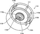
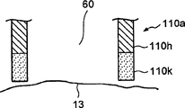
图19是表示图18的血液传感器组件中的支架的下端附近的一个结构例的主要部分的剖面图。Fig. 19 is a cross-sectional view of main parts showing an example of a structure near the lower end of the holder in the blood sensor unit of Fig. 18 .

图20是表示本发明的血液检查装置中的血液传感器组件的下端附近的另外一个结构例的主要部分的剖面图。20 is a cross-sectional view of main parts showing another example of the structure near the lower end of the blood sensor unit in the blood test apparatus of the present invention.

图21是表示本发明的血液检查装置中的血液传感器组件的下端附近的另一个示例的主要部分的剖面图。21 is a cross-sectional view of main parts showing another example of the vicinity of the lower end of the blood sensor unit in the blood test apparatus of the present invention.

图22是图18的血液传感器组件的剖面图。22 is a cross-sectional view of the blood sensor assembly of FIG. 18 .

图23是表示本发明的血液检查装置中的血液传感器组件的另一个示例的剖面图。Fig. 23 is a cross-sectional view showing another example of the blood sensor unit in the blood test apparatus of the present invention.

图24是表示本发明的血液检查装置中的血液传感器组件的另一个示例的剖面图。Fig. 24 is a cross-sectional view showing another example of the blood sensor unit in the blood test apparatus of the present invention.

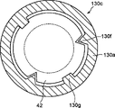
图25是图24的血液传感器组件的平面图。25 is a plan view of the blood sensor assembly of FIG. 24 .

图26是表示本发明的血液检查装置中的穿刺对象距激光焦点的距离(X轴)和烧灼图形(burn pattern)直径(Y轴)的关系的曲线图。26 is a graph showing the relationship between the distance (X-axis) of the puncture target from the laser focus and the diameter of the burn pattern (Y-axis) in the blood test apparatus of the present invention.

图27是表示本发明的血液检查装置中的负压室和负压径路的主要部分的一个示例的放大剖面图。27 is an enlarged cross-sectional view showing an example of a main part of a negative pressure chamber and a negative pressure path in the blood test apparatus of the present invention.

图28是表示发明的血液检查装置中的负压室和负压径路的主要部分的另一个示例的放大剖面图。Fig. 28 is an enlarged cross-sectional view showing another example of main parts of a negative pressure chamber and a negative pressure path in the blood test apparatus of the invention.

图29是图27所示的负压室的容积的说明图。Fig. 29 is an explanatory diagram of the volume of the negative pressure chamber shown in Fig. 27 .

图30是图28所示的负压室的容积的说明图。Fig. 30 is an explanatory diagram of the volume of the negative pressure chamber shown in Fig. 28 .

图31是本发明的血液检查装置中的电路部的方框图。Fig. 31 is a block diagram of a circuit unit in the blood test apparatus of the present invention.

图32是表示使用本发明的血液检查装置的检查步骤的一个示例的流程图。Fig. 32 is a flowchart showing an example of a test procedure using the blood test device of the present invention.

图33A是更具体地表示使用本发明的血液检查装置的检查步骤的各个步骤的一个示例的剖面图。33A is a cross-sectional view more specifically showing an example of each step of a test procedure using the blood test device of the present invention.

图33B是接续图33A后的各个步骤的剖面图。Fig. 33B is a cross-sectional view of each step following Fig. 33A.

图33C是接续图33B后的各个步骤的剖面图。Fig. 33C is a cross-sectional view of each step following Fig. 33B.

图33D是接续图33C后的各个步骤的剖面图。Fig. 33D is a cross-sectional view of each step following Fig. 33C.

图34是表示使用本发明的血液检查装置的检查步骤的另一个示例的流程图。Fig. 34 is a flowchart showing another example of a test procedure using the blood test device of the present invention.

图35是用于说明本发明的血液检查装置中的负压控制的一个示例的图。Fig. 35 is a diagram for explaining an example of negative pressure control in the blood test apparatus of the present invention.

图36是表示图35中所说明的负压控制造成皮肤的隆起的情形的示意图。FIG. 36 is a schematic diagram showing how the negative pressure control described in FIG. 35 causes skin swelling.

图37是用于说明本发明的血液检查装置中的负压控制的另一个示例的图。Fig. 37 is a diagram for explaining another example of negative pressure control in the blood test apparatus of the present invention.

图38是表示本发明的血液检查装置中所包含的激光穿孔装置的一个示 例的分解组装立体图。Fig. 38 is an exploded perspective view showing an example of a laser perforating device included in the blood test device of the present invention.

图39是表示本发明的血液检查装置中的激光分支控制的一个示例的图。Fig. 39 is a diagram showing an example of laser branch control in the blood test apparatus of the present invention.

图40是用于说明图39的激光分支控制的图。FIG. 40 is a diagram for explaining laser branch control in FIG. 39 .

图41是可用于图39的激光分支控制的立方体状光学元件的立体图。FIG. 41 is a perspective view of a cube-shaped optical element that may be used in the laser branching control of FIG. 39 .

图42是表示可用于图39的激光分支控制的立方体的一个示例的图,图42A是以立体的示意表示激光光线的分支的图,图42B是表示实现该分支的立方体的一个示例的立体图。42 is a diagram showing an example of a cube that can be used for laser branching control in FIG. 39 . FIG. 42A is a three-dimensional schematic diagram showing the branching of laser light, and FIG. 42B is a perspective view showing an example of a cube that realizes the branching.

图43是表示在本发明的血液检查装置中从斜方向照射激光光线而穿刺的情形的图。Fig. 43 is a diagram showing a state of puncturing by irradiating laser light from an oblique direction in the blood test apparatus of the present invention.

图44是表示激光光线的照射情形的变更的图。Fig. 44 is a diagram showing a change in the state of irradiation of laser beams.

图45是表示本发明的血液检查装置中的激光输出控制的另一个示例的简略图。Fig. 45 is a schematic diagram showing another example of laser output control in the blood test apparatus of the present invention.

图46是表示本发明的血液检查装置中的激光脉冲控制的一个示例的图。Fig. 46 is a diagram showing an example of laser pulse control in the blood test apparatus of the present invention.

图47是表示通过图46的激光脉冲控制的穿刺状态的剖面图。Fig. 47 is a cross-sectional view showing a state of puncturing by laser pulse control in Fig. 46 .

图48是表示本发明的血液检查装置中的激光输出控制的另一个示例的图,图48A是表示电路图,图48B是表示输入到闪光灯的输入电流的时间变化的图,图48C是表示激光输出的时间变化的图。48 is a diagram showing another example of laser output control in the blood test apparatus of the present invention, FIG. 48A is a circuit diagram, FIG. 48B is a diagram showing temporal changes in the input current to the flash lamp, and FIG. 48C is a diagram showing laser output. time-varying graph.

图49是表示本发明的血液检查装置中的激光输出控制的另一个示例的图,图49A是表示电路图,图49B是表示输入到闪光灯的输入电流的时间变化的图,图49C是表示激光输出的时间变化的图。49 is a diagram showing another example of laser output control in the blood test apparatus of the present invention, FIG. 49A is a circuit diagram, FIG. 49B is a diagram showing temporal changes in the input current to the flash lamp, and FIG. 49C is a diagram showing laser output. time-varying graph.

图50是表示本发明的血液检查装置的电源控制部的第一例的方框图。Fig. 50 is a block diagram showing a first example of a power control unit of the blood test apparatus of the present invention.

图51是表示图50的电源控制部的控制步骤的第一例的流程图。FIG. 51 is a flowchart showing a first example of a control procedure of the power supply control unit in FIG. 50 .

图52是表示图50的电源控制部的控制步骤的第二例的流程图。FIG. 52 is a flowchart showing a second example of the control procedure of the power supply control unit in FIG. 50 .

图53是表示图50的电源控制部的控制步骤的第三例的流程图。Fig. 53 is a flowchart showing a third example of the control procedure of the power supply control unit in Fig. 50 .

图54是表示图50的电源控制部的控制步骤的第四例的流程图。Fig. 54 is a flowchart showing a fourth example of the control procedure of the power supply control unit in Fig. 50 .

图55是表示本发明的血液检查装置的电源控制部的第二例的方框图。Fig. 55 is a block diagram showing a second example of the power control unit of the blood test apparatus of the present invention.

图56是表示图55的电源控制部的控制步骤的第一例的流程图。Fig. 56 is a flowchart showing a first example of a control procedure of the power supply control unit in Fig. 55 .

图57是表示图55的电源控制部的控制步骤的第二例的流程图。Fig. 57 is a flowchart showing a second example of the control procedure of the power supply control unit in Fig. 55 .

图58是表示本发明的血液检查装置的电源控制部的第三例的方框图。Fig. 58 is a block diagram showing a third example of the power control unit of the blood test apparatus of the present invention.

图59是表示图58的电源控制部的控制步骤的第一例的流程图。Fig. 59 is a flowchart showing a first example of a control procedure of the power supply control unit in Fig. 58 .

图60是表示图58的电源控制部的控制步骤的第二例的流程图。Fig. 60 is a flowchart showing a second example of the control procedure of the power supply control unit in Fig. 58 .

图61A是用于说明基于电池的余量,分段地设定用于对激光发射装置进行充电的充电量的方法的曲线图。FIG. 61A is a graph for explaining a method of setting the charging amount for charging the laser emitting device in stages based on the remaining amount of the battery.

图61B是用于说明基于电池的余量,连续地设定用于对激光发射装置进行充电的充电量的方法的曲线图。FIG. 61B is a graph for explaining a method of continuously setting the charging amount for charging the laser emitting device based on the remaining amount of the battery.

图61C是用于说明基于电池的余量,与可变曲线相应地设定用于对激光发射装置进行充电的充电量的方法的曲线图。FIG. 61C is a graph for explaining a method of setting a charging amount for charging the laser emitting device according to a variable curve based on the remaining amount of the battery.

图62是表示改变充电量时的、电池的电压(Y轴)和电池余量(X轴)之间的关系的曲线图。Fig. 62 is a graph showing the relationship between battery voltage (Y-axis) and battery remaining capacity (X-axis) when the charging amount is changed.

图63是表示包含本发明的激光穿孔装置的血液检查装置中的激光分支控制的另一个示例的图,图63A是表示两分支的情况的图,图63B是表示四分支的情况的图。63 is a diagram showing another example of laser branch control in a blood test apparatus including the laser perforation device of the present invention, FIG. 63A is a diagram showing a case of two branches, and FIG. 63B is a diagram showing a case of four branches.

图64是表示用于图63的激光分支控制的光纤定向耦合器的结构的简略图。Fig. 64 is a schematic diagram showing the structure of a fiber directional coupler used for laser branch control in Fig. 63 .

图65是表示包含本发明的激光穿孔装置的血液检查装置中的激光分支控制的另一个示例的图。Fig. 65 is a diagram showing another example of laser branching control in a blood test apparatus including the laser perforation apparatus of the present invention.

具体实施方式Detailed ways

以下,基于附图,说明本发明的血液检查装置。另外,对各个附图中公共的部件附加相同的标号,并适宜地省略其说明。Hereinafter, the blood test device of the present invention will be described based on the drawings. In addition, the same code|symbol is attached|subjected to the common part in each drawing, and the description is abbreviate|omitted suitably.

装置整体图1The overall picture of the device 1

图2是表示本发明的血液检查装置的整体结构的第一例的分解组装立体图。2 is an exploded perspective view showing a first example of the overall structure of the blood test device of the present invention.

图2所示的血液检查装置31的下盒32的内部容纳着:激光发射装置33、由吸引泵(负压泵)34a、泵阀组件34b和大气开放开关34c构成的负压部34、对电元件供给电能的电池35、安装在这些部件上的电路部36、以及安装在电路部36上并例如由液晶构成的显示部37等的构件。The inside of the lower box 32 of the blood testing device 31 shown in Figure 2 accommodates: a laser emitting device 33, a negative pressure part 34 composed of a suction pump (negative pressure pump) 34a, a pump valve assembly 34b and an atmosphere opening switch 34c, and A battery 35 for supplying electric energy to electric elements, a circuit unit 36 mounted on these components, and components such as a display unit 37 mounted on the circuit unit 36 and made of, for example, liquid crystal.

通过在容纳了各个部件的下外壳32上被覆上外壳38,构成装置主体39。在上外壳38中的与显示部37对应的位置设置有透明的显示窗38a。The device main body 39 is constituted by covering the lower case 32 accommodating various components with the upper case 38 . A transparent display window 38 a is provided at a position corresponding to the display unit 37 in the upper case 38 .

装置主体39通过适配器40与血液传感器组件44连接。适配器40的一端是圆筒状的筒体,血液传感器组件44对其装卸自如地安装。血液传感器组件44由支架41和安装在支架41的内部的血液传感器42构成。设置在血液 传感器组件44的中央的窗43为使来自激光发射装置33的激光发射口的激光光线通过的部分。窗43既可以为贯穿孔,也可以为以透过激光光线的材料形成的构件。The device main body 39 is connected to the blood sensor assembly 44 through the adapter 40 . One end of the adapter 40 is a cylindrical body to which the blood sensor unit 44 is detachably attached. The blood sensor unit 44 is composed of a bracket 41 and a blood sensor 42 mounted inside the bracket 41 . The window 43 provided at the center of the blood sensor unit 44 is a portion through which the laser light from the laser emitting port of the laser emitting device 33 passes. The window 43 may be a through hole or a member formed of a material that transmits laser light.

装置整体图2The overall picture of the device 2

图3是表示第二例本发明的血液检查装置的整体结构的分解组装立体图。图4是其侧面图。图3和图4所示的血液检查装置31a与图2所示的血液检查装置31的不同之处在于,具有能够手动吸引的手动泵作为构成负压部140的负压泵。以下说明该不同之处。Fig. 3 is an exploded perspective view showing the overall structure of a second example of the blood test apparatus of the present invention. Fig. 4 is its side view. Blood test apparatus 31a shown in FIGS. 3 and 4 is different from blood test apparatus 31 shown in FIG. This difference is described below.

血液检查装置31a具有负压部140,其包含手动泵(负压泵)141和以手动驱动手动泵141的手动泵142。大气释放开关144将在泵阀组件143中发生的负压释放到空气中。The blood test apparatus 31a has a negative pressure unit 140 including a manual pump (negative pressure pump) 141 and a manual pump 142 for manually driving the manual pump 141 . Atmospheric release switch 144 releases negative pressure occurring in pump valve assembly 143 to atmosphere.

手动泵旋钮142呈弓形,其一端被设为心轴142a,另一端被设为作用部142b(参照图4)。手动泵旋钮142能够以心轴142a为中心转动。作用部142b将动力传达给手动泵141。患者可将手动泵旋钮142与装置主机39一并抓握,使作用部142b上下运动。通过该上下运动,手动泵141开始动作而发生负压。The hand pump knob 142 has an arcuate shape, and one end thereof is used as a spindle 142a, and the other end is used as an action portion 142b (see FIG. 4 ). The hand pump knob 142 is rotatable about the spindle 142a. The action part 142b transmits power to the hand pump 141 . The patient can grasp the manual pump knob 142 together with the device main body 39 to move the action part 142b up and down. By this up and down movement, the manual pump 141 starts operating to generate a negative pressure.

为了确认通过作用部142b的上下运动的皮肤的隆起的同时施加适当的负压,优选由透明部件形成血液传感器组件44的封装,以便能够目视负压室60(参照图16)的内部。既可以使血液传感器组件44的封装全都以透明构件形成,也可以只使血液传感器组件44的前端41h一侧(负压室60一侧)以透明构件形成。也可以在手动泵旋钮142的被把持部142c上设置手指形状的凹凸而防止滑动。In order to apply an appropriate negative pressure while confirming the uplift of the skin by the vertical movement of the action part 142b, it is preferable to form the package of the blood sensor unit 44 with a transparent member so that the inside of the negative pressure chamber 60 (see FIG. 16 ) can be visually observed. The entire package of blood sensor unit 44 may be formed of a transparent member, or only the front end 41h side of blood sensor unit 44 (the negative pressure chamber 60 side) may be formed of a transparent member. Finger-shaped irregularities may be provided on the gripped portion 142c of the hand pump knob 142 to prevent slippage.

通过将负压部140设定为手动驱动,则无需用于驱动负压部140的电源。因此,能够实现电池35的长寿命化,适用于便携式的血液检查装置。By setting the negative pressure unit 140 to be manually driven, a power source for driving the negative pressure unit 140 becomes unnecessary. Therefore, the battery 35 can be extended in life, and it is suitable for a portable blood test device.

关于激光发射装置(包括透镜)的形式1Form 1 concerning laser emitting devices (including lenses)

本发明的血液检查装置31和31a利用激光作为用于穿刺皮肤的部件。使用激光光线照射皮肤,则皮肤的水的羟基吸收激光光线,瞬间产生热量而气化。此时,周围的细胞也一起气化而在皮肤上开孔。The blood test devices 31 and 31a of the present invention utilize laser light as a means for puncturing the skin. When the skin is irradiated with laser light, the hydroxyl group of the water in the skin absorbs the laser light and instantly generates heat and vaporizes. At this time, the surrounding cells are also gasified to open pores on the skin.

在血液检查装置31和31a中容纳有激光发射装置33。图5是血液检查装置31和31a中所容纳的激光发射装置33的外观立体图。另外,图6A和图6B分别是激光发射装置33的剖面图。在图6A中,激光结晶33d配置在设置了局部透镜33f和全反射镜33g的壁所包围的内部,而在图6B中,激光结晶 33d在其两侧面具有局部透镜33f和全反射镜33g,激光结晶33d安装在筒体33b的外壁和内壁(隔板)上。也就是说,在图6B中,激光结晶(激光晶棒,laserrod)33d变长,延伸到内壁(隔板)的前面。A laser emitting device 33 is accommodated in the blood test devices 31 and 31a. FIG. 5 is an external perspective view of the laser emitting device 33 accommodated in the blood testing devices 31 and 31a. In addition, FIGS. 6A and 6B are cross-sectional views of the laser emitting device 33, respectively. In Fig. 6A, laser crystallization 33d is disposed in the inside surrounded by the wall that is provided with partial lens 33f and total reflection mirror 33g, and in Fig. 6B, laser crystallization 33d has partial lens 33f and total reflection mirror 33g on its two sides, The laser crystal 33d is installed on the outer wall and the inner wall (partition plate) of the cylinder 33b. That is, in FIG. 6B, the laser crystal (laser rod, laserrod) 33d is elongated and extends to the front of the inner wall (spacer).

激光发射装置33由振荡管33a和连接在振荡管33a的前方的圆筒状的筒体33b构成。筒体33b的前方中央设置有激光发射口33c。The laser emitting device 33 is composed of an oscillating tube 33a and a cylindrical body 33b connected in front of the oscillating tube 33a. A laser emitting port 33c is provided at the front center of the barrel 33b.

在振荡管33a的内部,容纳有掺入铒的Er:YAG(钇铝石榴石)或掺入钬的Ho:YAG激光结晶33d、以及使用氙闪光灯的激发光源33e。在振荡管33a的一端,安装有局部透镜33f(尤其是图6A)。局部透镜33f的透过率设为约1%~10%即可。在振荡管33a的另一端,安装有99%~100%的全反射镜33g(图6A和图6B)。另外,也可以不使用局部透镜33f和全反射镜33g而在激光结晶33d的断面以溅射等形成具有同一特性的膜。Inside the oscillation tube 33a, an Er:YAG (yttrium aluminum garnet) doped with erbium or a Ho:YAG laser crystal 33d doped with holmium, and an excitation light source 33e using a xenon flash lamp are accommodated. At one end of the oscillating tube 33a, a partial lens 33f is installed (especially FIG. 6A). The transmittance of the partial lens 33f may be about 1% to 10%. At the other end of the oscillating tube 33a, a 99% to 100% total reflection mirror 33g is installed (FIGS. 6A and 6B). In addition, instead of using the partial lens 33f and the total reflection mirror 33g, a film having the same characteristics may be formed on the cross section of the laser crystal 33d by sputtering or the like.

筒体33b的内部安装有凸透镜(焦点透镜)33h。凸透镜33h将激光集光到血液传感器42的面的附近(后面论述细节)。全反射镜33g、YAG集光结晶33d、局部透镜33f、透镜33h和激光发射口33c,依照此顺序被配置。A convex lens (focus lens) 33h is attached to the inside of the cylindrical body 33b. The convex lens 33h collects the laser light near the surface of the blood sensor 42 (details will be discussed later). Total reflection mirror 33g, YAG light-collecting crystal 33d, partial lens 33f, lens 33h and laser emission port 33c are arranged in this order.

以下说明从激光发射装置33发射激光光线的步骤。从激发光源33e发射的激发光,例如进入到Er:YAG激光结晶33d的内部,激发Er(铒)离子,造成能量较高的状态而变得反转分布状态,全反射镜33g、YAG激光结晶33d和局部透镜33f之间反射而共振同时被放大。Ho(钬)的情况也相同。被放大的激光光线的一部分以感应发射(induced emission)通过局部透镜33f。通过了局部透镜33f的激光光线通过透镜33h从激光发射口33c放射。如后述那样,从激光发射口33c放射的激光光线穿刺(照射)皮肤。The procedure for emitting laser light from the laser emitting device 33 will be described below. The excitation light that emits from the excitation light source 33e enters, for example, the inside of Er:YAG laser crystal 33d, excites Er (erbium) ions, causes a higher state of energy and becomes an inverted distribution state, total reflection mirror 33g, YAG laser crystal 33d and the partial lens 33f reflect and resonate while being amplified. The same applies to Ho (holmium). A part of the amplified laser light passes through the partial lens 33f as induced emission. The laser light passing through the partial lens 33f is emitted from the laser emission port 33c through the lens 33h. As will be described later, the laser beam emitted from the laser emitting port 33c punctures (irradiates) the skin.

关于激光发射装置的形式2Regarding Form 2 of the laser emitting device

图7表示激光发射装置的另一个示例。图7所示的激光发射装置189将一个闪光灯185作为激发光源,以激发光照射两种激光结晶。此时,从各个结晶输出激光光线。通过利用两种结晶,能够输出激光光线的强度以及波长不同的激光光线。Fig. 7 shows another example of a laser emitting device. The laser emitting device 189 shown in FIG. 7 uses a flash lamp 185 as an excitation light source to irradiate two kinds of laser crystals with excitation light. At this time, laser light is output from each crystal. By using two types of crystals, it is possible to output laser light having different intensities and wavelengths of laser light.

如图7所示,激光发射装置189包括:外壳188,呈将两个断面为椭圆形的筒体重叠的形状;闪光灯185,用于激发配置在外壳188的中央部的激光;以及第一结晶186和第二结晶187,配置在闪光灯185的两侧,并用于激光振荡。椭圆形的外壳188存在三个焦点。由于外壳188呈两个椭圆重叠的形状,各个椭圆都有两个焦点,但是因为配置得使其中的一个焦点为公共 的焦点,所以存在三个焦点。在三个焦点中,在一个焦点配置第一结晶186,在另一个焦点配置第二结晶187。然后,将闪光灯185配置在共有两个焦点的中央部。以一个闪光灯185能够从两个结晶186和187的每个都得到激光光线,因此能够实现激光发射装置的小型化和廉价。As shown in Figure 7, the laser emitting device 189 includes: a housing 188, which is in the shape of overlapping two cylindrical bodies with an oval cross section; 186 and the second crystal 187 are arranged on both sides of the flash lamp 185 and used for laser oscillation. There are three foci of the elliptical housing 188 . Since the housing 188 is in the shape of two overlapping ellipses, each ellipse has two foci, but because it is configured so that one of the foci is a common focus, there are three foci. Among the three focal points, the first crystal 186 is placed at one focus, and the second crystal 187 is placed at the other focus. Then, the strobe 185 is arranged at the central portion where two focal points are shared. Laser light can be obtained from each of the two crystals 186 and 187 with one flash lamp 185, so that the laser emitting device can be miniaturized and inexpensive.

虽然激光的输出强度也与闪光灯185的发光强度成比例,但是也与结晶186以及结晶187的体积成比例。因此,若配置直径相同但长度不同的两个结晶,则可用一个闪光灯185得到强度不同的两个激光光线。The output intensity of the laser light is also proportional to the light intensity of the flash lamp 185 , but also proportional to the volumes of the crystal 186 and the crystal 187 . Therefore, if two crystals having the same diameter but different lengths are arranged, one flash lamp 185 can be used to obtain two laser beams with different intensities.

另外,若使用相同体积的结晶,则可同时输出相同强度的两个激光光线。因此,即使不将激光光线分支(参照图40和图41),也可以用相同强度的激光光线穿刺皮肤。此时,不存在因分支的分光器和反光镜所造成的能量损失。In addition, if crystals of the same volume are used, two laser beams of the same intensity can be simultaneously output. Therefore, even without branching the laser light (see FIGS. 40 and 41 ), it is possible to puncture the skin with the same intensity laser light. At this time, there is no energy loss due to branched beam splitters and mirrors.

若配置组成不同的两个结晶(例如,波长2.94μm的Er:YAG激光的结晶以及波长1.06μm的Nd:YAG激光的结晶),则可得到波长不同的激光光线。使用不同波长的激光光线照射在相同的位置,则可在皮肤产生深度不同的损伤。例如,Er:YAG和Nd:YAG的羟基的吸收效率不同。于是,可用吸收效率高的Er:YAG产生较浅的损伤,用吸收效率低于Er:YAG的Nd:YAG产生较深的损伤。利用该性质,同时照射两个激光光线,能够更有效地在皮肤上产生损伤。在照射两个激光光线的情况下,优选给出一些时间差,并按Er:YAG和Nd:YAG的顺序照射。By arranging two crystals with different compositions (for example, a crystal of Er:YAG laser with a wavelength of 2.94 μm and a crystal of Nd:YAG laser with a wavelength of 1.06 μm), laser light with different wavelengths can be obtained. Different wavelengths of laser light can be used to irradiate the same position, and different depths of damage can be produced in the skin. For example, Er:YAG and Nd:YAG have different absorption efficiencies of hydroxyl groups. Thus, Er:YAG, which has a high absorption efficiency, can be used to produce shallower lesions, and Nd:YAG, which has a lower absorption efficiency than Er:YAG, can be used to produce deeper lesions. Utilizing this property, irradiating two laser beams at the same time can damage the skin more effectively. In the case of irradiating two laser rays, it is preferable to give some time difference and irradiate in the order of Er:YAG and Nd:YAG.

若使用激光发射装置189,则可选择激光光线的波长来使用。另外,利用光学系使两种激光光线照射在相同的位置,则可提高输出强度。If the laser emitting device 189 is used, the wavelength of the laser light can be selected for use. In addition, by using the optical system to irradiate the two laser beams at the same position, the output intensity can be increased.

本发明的血液检查装置31和31a因为利用不与皮肤接触即可进行穿刺的激光发射装置33和189作为穿刺患者皮肤的部件,所以无需现有的血液检查装置所需的穿刺针。另外,因为利用与患者的皮肤非接触的穿刺部,所以很卫生。另外,以往需要每次检查后更换穿刺针,但通过本发明的血液检查装置31和31a的检查,则无需该更换作业。The blood test devices 31 and 31a of the present invention do not need the puncture needles required by the existing blood test devices because the laser emitting devices 33 and 189 that can puncture without contact with the skin are used as parts for puncturing the patient's skin. In addition, it is hygienic because the puncturing part which does not come into contact with the patient's skin is used. In addition, conventionally, it was necessary to replace the puncture needle after each test, but the blood test devices 31 and 31a of the present invention eliminate the need for such replacement work.

另外,在本发明的血液检查装置31和31a中不需要在使用针的穿刺中所需的使针运动的可动部件,因此可减少故障。另外,本发明的血液检查装置31和31a所需的部件数较少,所以易于管理部件。另外,若在激光发射口33c的前面设置透明的防水壁,则可对血液检查装置31和31a的整体进行完整清洗。In addition, the blood test apparatuses 31 and 31a according to the present invention do not require a movable part for moving the needle, which is necessary for puncturing with a needle, so that troubles can be reduced. In addition, the blood test apparatuses 31 and 31a of the present invention require a small number of components, so that management of the components is easy. In addition, if a transparent waterproof wall is provided in front of the laser emission port 33c, the entire blood test apparatuses 31 and 31a can be completely cleaned.

关于血液传感器About Blood Sensors

本发明的血液检查装置31和31a具有用于引入从被穿刺的皮肤流出的血液、并检查该血液成分等的血液传感器。The blood test devices 31 and 31a of the present invention have a blood sensor for introducing blood flowing out from punctured skin, and checking the blood components and the like.

血液传感器的第一例First example of a blood sensor

图8是血液传感器的第一例的剖面图。如图8所示的血液传感器42的外形呈圆形或者多边形。构成血液传感器42的基体45包括:基板46;粘结在基板46的上面的隔片47;以及粘结在隔片47的上面的罩48。Fig. 8 is a cross-sectional view of the first example of the blood sensor. The shape of the blood sensor 42 shown in FIG. 8 is circular or polygonal. Base body 45 constituting blood sensor 42 includes: substrate 46 ; spacer 47 bonded to the upper surface of substrate 46 ; and cover 48 bonded to the upper surface of spacer 47 .

在基体45的大约中央设置有血液的容纳部49。设置在基板46的孔46a与设置在隔片47的孔47a连通而形成容纳部49。容纳部49朝向下方具有开口,以采取来自皮肤的血液。容纳部49的容积并不特别限定,例如设为0.904μL即可。供给路径50的一端与容纳部49连接。供给路径50的容积并不特别限定,例如设为0.144μL即可。供给路径50的内部配置检测部51。A blood receptacle 49 is arranged approximately in the center of the main body 45 . The hole 46 a provided in the base plate 46 communicates with the hole 47 a provided in the spacer 47 to form an accommodating portion 49 . The receiving portion 49 has an opening facing downward to collect blood from the skin. The volume of the housing portion 49 is not particularly limited, and may be 0.904 μL, for example. One end of the supply path 50 is connected to the accommodating portion 49 . The volume of the supply path 50 is not particularly limited, and may be set at, for example, 0.144 μL. A detection unit 51 is arranged inside the supply path 50 .

容纳部49中贮存的血液通过毛细管现象导入到供给路径50,并导入到检测部51。供给路径50的另一端与空气孔52连接。空气孔52的直径设为50μm~250μm左右即可。若缩小空气孔52的直径,则可抑制来自空气孔52的血液的过多流出。另外,在皮肤紧贴到容纳部49的状态下,空气孔52还作为对容纳部49内施加负压的负压路径而发挥作用。The blood stored in the storage unit 49 is introduced into the supply channel 50 by capillary action, and then introduced into the detection unit 51 . The other end of the supply path 50 is connected to the air hole 52 . The diameter of the air hole 52 may be about 50 μm to 250 μm. If the diameter of the air hole 52 is reduced, excessive outflow of blood from the air hole 52 can be suppressed. In addition, the air hole 52 also functions as a negative pressure path for applying negative pressure to the inside of the housing part 49 in a state where the skin is in close contact with the housing part 49 .

在检测部51上载置的试剂53根据检查对象适当地调剂即可。例如,在0.01~2.0wt%CMC(carboxymethyl cellulose,羧甲基纤维素)水溶液中,添加酶(PQQ-GDH)使其成为0.1~5.0U/传感器、添加铁氰化钾(potassiumferricyanide)使其成为10~200mM、添加麦芽糖醇(maltitol)使其成为1~50mM、以及添加牛黄酸(taurine)使其成为20~200mM,将使它们溶解而调配成的试剂溶液滴落在配置在基板46上的检测部51上,使其干燥而得到试剂53。The reagent 53 placed on the detection unit 51 may be appropriately adjusted according to the test object. For example, in 0.01-2.0wt% CMC (carboxymethylcellulose, carboxymethylcellulose) aqueous solution, add enzyme (PQQ-GDH) to make it 0.1-5.0U/sensor, add potassium ferricyanide (potassiumferricyanide) to make it 10 to 200 mM, maltitol (maltitol) was added to make it 1 to 50 mM, and taurine (taurine) was added to make it 20 to 200 mM, and the reagent solution prepared by dissolving them was dropped on the reagent solution arranged on the substrate 46 . On the detection part 51, it is dried and the reagent 53 is obtained.

血液传感器42的容纳部49以面49a(以下也称为“上表面”)被封闭。The accommodating portion 49 of the blood sensor 42 is closed with a surface 49a (hereinafter also referred to as "upper surface").

若使被照射的激光光线透过上表面49a,则优选不使从激光光线所穿刺的皮肤流出的血液从上表面49a流出。为了使激光光线从上表面49a透过,使罩48以激光光线可透过的材料(例如包括玻璃、聚酰亚胺(polyimide)等的塑料、或者树脂类材料)形成即可。If the irradiated laser light is transmitted through the upper surface 49a, it is preferable not to allow the blood flowing out from the skin punctured by the laser light to flow out from the upper surface 49a. In order to transmit the laser beam from the upper surface 49a, the cover 48 may be formed of a material (for example, glass, plastic such as polyimide, or a resin material) that transmits the laser beam.

另外,被照射的激光光线无法从上表面49a透过的情况下,该激光光线能够穿孔上表面49a即可。在激光光线穿孔上表面49a的情况下,基板46、隔片47以及罩48可以用相同的材料形成。In addition, when the irradiated laser beam cannot pass through the upper surface 49a, it is sufficient that the laser beam can penetrate the upper surface 49a. In the case where the laser light perforates the upper surface 49a, the substrate 46, the spacer 47, and the cover 48 may be formed of the same material.

在上表面49a形成了的孔可以与空气孔52一起成为用于负压部件对容纳部49施加负压的负压路径。The holes formed in the upper surface 49 a together with the air holes 52 can serve as a negative pressure path for a negative pressure member to apply a negative pressure to the accommodating portion 49 .

血液传感器的第二例Second example of blood sensor

图9是第二例血液传感器的剖面图。虽然图8所示的血液传感器42的容纳部49的上表面49a被封闭,但是图9所示的血液传感器103的容纳部49的上表面是敞开的。Fig. 9 is a sectional view of a second example of a blood sensor. While the upper surface 49a of the accommodating portion 49 of the blood sensor 42 shown in FIG. 8 is closed, the upper surface of the accommodating portion 49 of the blood sensor 103 shown in FIG. 9 is opened.

在血液传感器103的罩48形成有孔103b。优选孔103b的直径(例如1.0mm)为比容纳部49的直径(例如2.0mm)小的直径,并比空气孔52的直径(50μm~250μm)大。优选是孔103b位于容纳部49的上表面中央。激光通过孔103b穿刺皮肤。通过设置孔103b,可抑制激光的衰减。因此,能够减小进行照射的激光的能量。A hole 103 b is formed in the cover 48 of the blood sensor 103 . The hole 103 b preferably has a diameter (for example, 1.0 mm) smaller than a diameter (for example, 2.0 mm) of the accommodation portion 49 and larger than a diameter (50 μm to 250 μm) of the air hole 52 . Preferably, the hole 103 b is located at the center of the upper surface of the receiving portion 49 . The laser punctures the skin through the hole 103b. Attenuation of laser light can be suppressed by providing the hole 103b. Therefore, the energy of laser light to be irradiated can be reduced.

孔103b可以与空气孔52一起成为用于负压部34和140对容纳部49施加负压的负压路径。The hole 103 b may become a negative pressure path for the negative pressure parts 34 and 140 to apply a negative pressure to the accommodation part 49 together with the air hole 52 .

如图10所示,孔103b的内侧产生的血液16的表面张力抑制通过皮肤穿刺采取了的血液16流出到罩上面。血液16遍布到容纳部49的内部。因此,能够采取适当量的血液16。贮满了存储部49的血液16通过毛细管现象流入到供给路径50。As shown in FIG. 10, the surface tension of the blood 16 generated inside the hole 103b suppresses the blood 16 collected by skin puncture from flowing out to the top of the cover. The blood 16 spreads into the interior of the receptacle 49 . Therefore, an appropriate amount of blood 16 can be collected. The blood 16 filled with the storage part 49 flows into the supply channel 50 by the capillary phenomenon.

若使孔103b具有防水性,则血液16更不易从孔103b溢出。因此,血液检查装置31和31a的内部不会被血液污染。If the hole 103b is waterproof, the blood 16 is less likely to overflow from the hole 103b. Therefore, the insides of the blood test devices 31 and 31a are not contaminated with blood.

血液传感器103的罩48的材料可以使用聚对苯二甲酸乙二醇酯(PET:polyethylene terephthalate)等,也可以使用与基板46和隔片47同样的材料。因此,易于材料管理。The material of cover 48 of blood sensor 103 may be polyethylene terephthalate (PET: polyethylene terephthalate), or the same material as substrate 46 and spacer 47 . Therefore, material management is easy.

激光光线虽然通过存储部49的孔103b,但是既可以使其通过孔103b的中心,也可以使其通过离开孔103b的中心的位置。例如,若使激光光线从孔103b的中心,从远离供给路径50的位置通过,则从皮肤13流出的血液16在确实地贮满存储部49的内部之后,流入供给路径50。从而,能够进行精度高的测定。Although the laser beam passes through the hole 103b of the storage unit 49, it may pass through the center of the hole 103b, or may pass through a position away from the center of the hole 103b. For example, if the laser light passes through the center of the hole 103 b at a position away from the supply path 50 , the blood 16 flowing out from the skin 13 will flow into the supply path 50 after the inside of the storage unit 49 is reliably filled. Therefore, high-precision measurement can be performed.

对于血液传感器103而言,预先在容纳部49的上表面形成孔103b。因为这样预先形成有孔103b,所以无需将激光的轴对准到应穿孔的地方。因此,易于将血液传感器103安装到血液传感器组件44。优选是将孔103b缩小为0.05~0.25mm左右即可,抑制来自穿刺孔的血液16的流出。For blood sensor 103 , hole 103 b is formed in advance on the upper surface of housing portion 49 . Since the hole 103b is formed in advance in this way, there is no need to align the axis of the laser light to the place where the hole should be punched. Therefore, it is easy to mount blood sensor 103 to blood sensor assembly 44 . It is preferable to reduce the hole 103b to about 0.05 to 0.25 mm to suppress the outflow of the blood 16 from the puncture hole.

如图8和图9所示,在本发明的血液检查装置31和31a中的血液传感器42和103优选具有容纳部49和供给路径50。供给路径50的内壁面优选具有亲水性。这是为了使血液流畅地送入配置了检测部51的供给路径50。另外,优选是供给路径50的内壁面的亲水性比容纳部49的内壁面的亲水性强。这是为了使贮存在容纳部49的血液流畅地供给到供给路径50。As shown in FIGS. 8 and 9 , the blood sensors 42 and 103 in the blood test apparatuses 31 and 31 a of the present invention preferably have an accommodating portion 49 and a supply path 50 . The inner wall surface of the supply path 50 is preferably hydrophilic. This is to smoothly send blood into the supply channel 50 where the detection unit 51 is arranged. In addition, it is preferable that the inner wall surface of the supply path 50 is more hydrophilic than the inner wall surface of the housing portion 49 . This is for the purpose of smoothly supplying the blood stored in the storage portion 49 to the supply channel 50 .

另外,在本发明的血液检查装置31和31a中的血液传感器42和103如图8以及图9所示那样,具有罩48,罩48形成容纳部49的上表面。罩48的上面48a和103a(激光所照射的面)优选具有防水性。另外,罩48的上面48a和103a的防水性优选比容纳部49的内壁面的防水性强。这是为了防止贮存在容纳部49的血液从形成在罩48的孔(激光穿孔形成的孔或者孔103b)流出。In addition, as shown in FIGS. 8 and 9 , blood sensors 42 and 103 in blood test apparatuses 31 and 31 a of the present invention have cover 48 forming the upper surface of housing portion 49 . The upper surfaces 48a and 103a (surfaces irradiated with laser light) of the cover 48 are preferably waterproof. In addition, the waterproofness of the upper surfaces 48 a and 103 a of the cover 48 is preferably stronger than that of the inner wall surface of the housing portion 49 . This is to prevent the blood stored in the container portion 49 from flowing out from the hole formed in the cover 48 (the hole formed by laser perforation or the hole 103 b ).

血液传感器的第三例Third example of blood sensor

患者的皮肤13的湿润程度因环境而不同。The degree of moisture of the patient's skin 13 varies depending on the environment.

另一方面,优选是被激光穿刺的皮肤13具有适当的水分。于是,优选通过预先润湿进行激光穿刺前的皮肤13的附近,给予皮肤13适当的水分而将湿润程度保持一定。这是为了以稳定的条件进行测定。On the other hand, it is preferable that the skin 13 to be punctured by the laser has appropriate moisture. Therefore, it is preferable to moisten the vicinity of the skin 13 before laser puncturing and give the skin 13 an appropriate amount of water to maintain a constant degree of moisture. This is to perform measurement under stable conditions.

图11表示在血液传感器42(详情参照图8)的与皮肤13抵接的下面一侧,设置了用于贮存水的水容纳部195的血液传感器42a。图11所示的血液传感器42a在照射激光光线时,或者在激光光线照射之前皮肤通过负压部34和140被隆起时,水存储部195破裂而对皮肤13洒上定量的水,从而润湿皮肤。水容纳部195为例如容纳水的PET等的塑料材料的容器,也可为更柔软的水囊(bag),还可以为渗入水的海绵或者绵状构件。其中,优选不在通过激光光线的透过部分196配置水存储部195。这是因为水会减少激光光线的强度。FIG. 11 shows a blood sensor 42a in which a water storage portion 195 for storing water is provided on the underside of the blood sensor 42 (see FIG. 8 for details) in contact with the skin 13 . When the blood sensor 42a shown in FIG. 11 is irradiated with laser light, or when the skin is raised by the negative pressure parts 34 and 140 before the laser light is irradiated, the water storage part 195 is ruptured and a certain amount of water is sprinkled on the skin 13, thereby moistening the skin. skin. The water container 195 is, for example, a container made of a plastic material such as PET for containing water, or may be a softer water bag, or may be a sponge or a cotton-like member soaked in water. Among them, it is preferable not to arrange the water storage part 195 in the transmission part 196 through which the laser light passes. This is because water reduces the intensity of the laser light.

血液传感器的透视平面图1Perspective Plan of Blood Sensor 1

图12是血液传感器42的透视平面图。血液传感器42配置有检测电极54~57,从容纳部49向空气孔52,依序为检测电极57(Hct(血细胞比容)极)、检测电极56(对极)、检测电极54(有效极)、检测电极56(对极)以及检测电极(检测极)。检测部51配置有检测电极54~56。FIG. 12 is a perspective plan view of blood sensor 42 . The blood sensor 42 is equipped with detection electrodes 54 to 57. From the housing part 49 to the air hole 52, the detection electrode 57 (Hct (hematocrit) pole), the detection electrode 56 (opposite pole), and the detection electrode 54 (active pole) are in order. ), the detection electrode 56 (opposite pole) and the detection electrode (detection pole). The detection unit 51 is provided with detection electrodes 54 to 56 .

检测电极54~57的每个电极与连接电极54a~57a连接。连接电极54a~57a延伸到基板46的外周为止。连接电极54a~57a的每个电极设置有接触部 位54b~57b。另外,连接电极56a除了接触部位56b还设置有接触部位56c,形成两个接触部位。基准电极56d也可以设置在连接电极56a以外的连接电极(54a、55a以及57a)。Each of the detection electrodes 54 to 57 is connected to the connection electrodes 54a to 57a. The connection electrodes 54 a to 57 a extend to the outer periphery of the substrate 46 . Each of the connection electrodes 54a-57a is provided with a contact site 54b-57b. Moreover, the connection electrode 56a is provided with the contact part 56c other than the contact part 56b, and forms two contact parts. The reference electrode 56d may be provided on connection electrodes (54a, 55a, and 57a) other than the connection electrode 56a.

接触部位54b~57b以及接触部位56c在传感器42的外周附近被大致等间隔地配置。The contact parts 54 b to 57 b and the contact part 56 c are arranged at substantially equal intervals near the outer periphery of the sensor 42 .

各个接触部位54b~57b以及接触部位56c中,接触部位56b与接触部位56c导通,而其它接触部位之间绝缘。Among the contact parts 54b to 57b and the contact part 56c, the contact part 56b is electrically connected to the contact part 56c, and the other contact parts are insulated.

使接触部位56c为基准接触部位,也就是作为基准电极56d使用,能够确定各个连接电极。也就是说,以电路部36(参照图2)测定相邻的接触部位的绝缘电阻,将绝缘电阻为零的接触部位确定为基准电极56d。将基准电极56d为基准,以顺时针确定连接电极56a、连接电极57a、连接电极54a以及连接电极55a。By using the contact portion 56c as a reference contact portion, that is, as a reference electrode 56d, each connection electrode can be specified. That is, the insulation resistance of the adjacent contact portion is measured by the circuit unit 36 (see FIG. 2 ), and the contact portion whose insulation resistance is zero is identified as the reference electrode 56d. The connection electrode 56a, the connection electrode 57a, the connection electrode 54a, and the connection electrode 55a are determined clockwise with the reference electrode 56d as a reference.

这样,血液传感器42具有基准电极56d,因此能够确定各个连接电极。因此,即使接触部位(54b~57b和56c)任意地与设置在装置本机39的五个连接器的每个连接,各个连接电极被确定而能够进行测定。因此,能够使血液传感器42(或者包括血液传感器42的血液传感器组件44)成为对称形状,从而轻而易举地安装到装置主机39,安装作业变得非常简单。In this way, since blood sensor 42 has reference electrode 56d, each connection electrode can be identified. Therefore, even if the contact points (54b to 57b and 56c) are randomly connected to each of the five connectors provided on the main body 39 of the device, each connection electrode is determined and can be measured. Therefore, blood sensor 42 (or blood sensor unit 44 including blood sensor 42 ) can be made into a symmetrical shape, and can be easily mounted on device main body 39 , and the mounting work becomes very simple.

还可以在基板46的外周上设置定位凹部46c。在隔片47和罩48的各自的外周上,与定位凹部46c对应地设置有定位凹部47c和48c。通过定位凹部46c~48c,能够将血液传感器42对准到血液传感器组件44的规定位置而安装。A positioning recess 46 c may also be provided on the outer periphery of the base plate 46 . On the respective outer peripheries of the spacer 47 and the cover 48, positioning recesses 47c and 48c are provided corresponding to the positioning recess 46c. The blood sensor 42 can be aligned to a predetermined position of the blood sensor unit 44 by the positioning recesses 46c to 48c, and can be mounted.

血液传感器的透视平面图2Perspective Plan of Blood Sensor 2

图13是圆形的血液传感器的透视平面图。图13所示的血液传感器101与血液传感器42(参照图12)的不同之处在于:从连接电极56a通过规定的图案形成基准电极56d。以下以该不同之处为中心进行说明。13 is a perspective plan view of a circular blood sensor. Blood sensor 101 shown in FIG. 13 differs from blood sensor 42 (see FIG. 12 ) in that reference electrode 56 d is formed in a predetermined pattern from connection electrode 56 a. The following description will focus on this difference.

基准接触部位56c设置在基准电极56d。基准接触部位56c以及接触部位54b~57b分别以相同的间隔被配置在外周附近。也就是说,以接触部位54b、55b、56b、56c以及57b形成正五边形。The reference contact portion 56c is provided on the reference electrode 56d. The reference contact portion 56c and the contact portions 54b to 57b are respectively arranged at the same intervals in the vicinity of the outer periphery. That is, a regular pentagon is formed by the contact portions 54b, 55b, 56b, 56c, and 57b.

连接电极56a与基准电极56d之间用激光加工过的图案(pattern)56e连接。通过改变图案56e的宽度,能够改变接触部位56b与基准接触部位56c之间的电阻值。基准电极56d为确定连接电极54a~57a的位置的基准。The connection electrode 56a and the reference electrode 56d are connected by a laser-processed pattern (pattern) 56e. By changing the width of the pattern 56e, the resistance value between the contact portion 56b and the reference contact portion 56c can be changed. The reference electrode 56d is a reference for determining the positions of the connection electrodes 54a to 57a.

基准电极56d可用于识别血液传感器101的产品规格。例如,设定为:若图案56e的电阻值为200欧姆~1000欧姆,则使用校准曲线1;若电阻值为1000欧姆~2000欧姆,则使用校准曲线2;若电阻值为2000欧姆~3000欧姆,则使用校准曲线3,自动地识别该传感器的校准曲线,使用最佳的校准曲线来测定血糖值。The reference electrode 56d can be used to identify the product specification of the blood sensor 101 . For example, it is set as follows: if the resistance value of the pattern 56e is 200 ohms to 1000 ohms, use calibration curve 1; if the resistance value is 1000 ohms to 2000 ohms, then use calibration curve 2; if the resistance value is 2000 ohms to 3000 ohms , then use the calibration curve 3 to automatically identify the calibration curve of the sensor, and use the best calibration curve to measure the blood glucose level.

基准电极除了可用于校准曲线的自动识别之外,还可用于各种产品规格的识别。例如,能够像A公司规格、B公司规格那样,用于出厂目的地的用户的识别。In addition to being used for automatic identification of calibration curves, reference electrodes can also be used for identification of various product specifications. For example, it can be used for identification of the user at the shipping destination as in company A specification and company B specification.

用图案56e形成具有各种各样的值的电感,将该电感连接到构成振荡器的谐振器,并根据该电感的值的不同来改变振荡频率,从而能够保持各种各样的信息。Various types of information can be held by forming inductance with various values using the pattern 56e, connecting the inductance to a resonator constituting an oscillator, and changing the oscillation frequency according to the value of the inductance.

通过设置基准电极56d,将血液传感器组件44安装在血液检查装置31和31a时,即使以任意的角度安装,也能够确定各个连接电极54a~57a,所述角度是以安装方向为轴的旋转角度。因此,在血液传感器组件44的安装中,无需通过目视等对准安装方向,从而易于安装。By providing the reference electrode 56d, when the blood sensor unit 44 is mounted on the blood test devices 31 and 31a, even if it is mounted at an arbitrary angle, the respective connection electrodes 54a to 57a can be determined. The angle is the rotation angle with the mounting direction as the axis. . Therefore, in the installation of the blood sensor unit 44, it is not necessary to align the installation direction by visual inspection or the like, so that the installation is easy.

血液传感器的透视平面图3Perspective Plan of Blood Sensor 3

图14是呈四边形的血液传感器的透视平面图。虽然图14所示的血液传感器102的外形为四边形,但是也可以为六边形或八边形等的多边形。使其为四边形或者六边形,则可提高取材的出成率。另外,也可以如图14所示那样,在四边中的一边设置与血液传感器组件44之间的定位凹部102a而使其为非对称形。凹部102a成为将血液传感器102安装到血液传感器组件44时的基准。另外,若将与凹部102a结合的血液传感器组件44一侧的凸部130f(参照图25)作为基准,对准与适配器40之间的位置,则即使不设置基准电极56d也能够确定连接电极54a~57a的位置。Fig. 14 is a perspective plan view of a quadrangular blood sensor. Although the outer shape of blood sensor 102 shown in FIG. 14 is a quadrangle, it may be a polygon such as a hexagon or an octagon. Making it quadrilateral or hexagonal can improve the yield of materials. In addition, as shown in FIG. 14 , a positioning recess 102 a between the blood sensor unit 44 may be provided on one of the four sides so as to have an asymmetrical shape. Recess 102 a serves as a reference when blood sensor 102 is attached to blood sensor unit 44 . In addition, if the convex portion 130f (see FIG. 25 ) on the side of the blood sensor unit 44 coupled to the concave portion 102a is used as a reference, and the position between the adapter 40 is aligned, the connection electrode 54a can be identified without providing the reference electrode 56d. The position of ~57a.

在四边形的基板102b的各个角设置有接触部位54b~57b。隔片102c以及在罩102d粘合在基板102b。基板102b与基板46对应,隔片102c与隔片47对应,罩102d与罩48对应(参照图8)。Contact portions 54b to 57b are provided at respective corners of the quadrangular substrate 102b. The spacer 102c and the cover 102d are bonded to the base plate 102b. The substrate 102b corresponds to the substrate 46, the spacer 102c corresponds to the spacer 47, and the cover 102d corresponds to the cover 48 (see FIG. 8).

血液传感器的分解平面图An exploded plan view of a blood sensor

说明本发明的血液检查装置31和31a所具有的血液传感器42(参照图8)的组装和材料。The assembly and materials of blood sensor 42 (see FIG. 8 ) included in blood test apparatuses 31 and 31a of the present invention will be described.

图15是血液传感器42的分解平面图。图15A是罩48的平面图,图15B 是隔片47的平面图,图15C是基板46的平面图。FIG. 15 is an exploded plan view of blood sensor 42 . 15A is a plan view of the cover 48, FIG. 15B is a plan view of the spacer 47, and FIG. 15C is a plan view of the substrate 46.

图15C为构成血液传感器42的、呈圆形的基板46的平面图。基板46的直径约为8.0mm即可。基板46的材料为聚对苯二甲酸乙二醇酯(PET)等的树脂,其厚度约为0.075~0.250mm(例如为0.188mm)。FIG. 15C is a plan view of a circular substrate 46 constituting blood sensor 42 . The diameter of the substrate 46 should just be about 8.0 mm. The material of the substrate 46 is resin such as polyethylene terephthalate (PET), and its thickness is about 0.075-0.250 mm (for example, 0.188 mm).

在基板46的上面,一体地形成有检测电极54~57,以及从检测电极54~57的每个电极导出的连接电极54a~57a。以金、白金、或者钯等作为材料,通过溅射法或者蒸镀法形成导电层,并对其进行激光加工来形成检测电极以及连接电极即可。On the upper surface of the substrate 46 , detection electrodes 54 to 57 and connection electrodes 54 a to 57 a derived from each of the detection electrodes 54 to 57 are integrally formed. A conductive layer may be formed by sputtering or vapor deposition using gold, platinum, or palladium as a material, and the detection electrode and the connection electrode may be formed by laser processing.

设置在基板46的大约中央的孔46a的直径约为2.0mm即可。优选是孔46a的壁面具有比供给路径50弱的亲水性,或者具有比罩48的上面48a弱的防水性。The diameter of the hole 46 a provided in the approximate center of the substrate 46 may be approximately 2.0 mm. Preferably, the wall surface of the hole 46 a is less hydrophilic than the supply path 50 or less waterproof than the upper surface 48 a of the cover 48 .

优选是孔46a从检测电极54~57一侧,利用凸模钻孔而形成。这是因为从检测电极54~57一侧钻孔,则不简单对检测电极54~57造成损伤。另外,即使因为钻孔而在孔46a产生了毛刺(burr),该毛刺也朝向下方(皮肤一侧)。因此,可防止来自容纳部49的血液16的流出。设置在基板46的外周上的用于定位的凹部46c与在血液传感器组件44的筒体41e形成的用于定位的凸部41j(都参照图16)咬合。因此,血液传感器42的安装到血液传感器组件44的位置被决定。It is preferable that the holes 46a are formed by punch drilling from the side of the detection electrodes 54 to 57 . This is because the detection electrodes 54 to 57 are not easily damaged by drilling holes from the side of the detection electrodes 54 to 57 . In addition, even if a burr is generated in the hole 46a due to drilling, the burr is directed downward (skin side). Therefore, the outflow of the blood 16 from the accommodation part 49 can be prevented. The positioning concave portion 46c provided on the outer periphery of the base plate 46 engages with the positioning convex portion 41j (both refer to FIG. 16 ) formed on the cylinder body 41e of the blood sensor unit 44 . Therefore, the position where blood sensor 42 is attached to blood sensor unit 44 is determined.

图15B是隔片47的平面图。隔片47的直径约为5.2mm即可。隔片47的材料为聚对苯二甲酸乙二醇酯(PET)等的树脂即可,其厚度约为0.025~0.25mm(例如为0.1mm)即可。FIG. 15B is a plan view of the spacer 47 . The diameter of the spacer 47 is about 5.2 mm. The material of the spacer 47 may be resin such as polyethylene terephthalate (PET), and its thickness may be about 0.025-0.25 mm (for example, 0.1 mm).

设置在隔片47的大致中央的孔47a的直径为2.0mm,而且与设置在基板46的孔46a对应的位置。优选是孔47a的壁面具有比供给路径50弱的亲水性,或者具有比罩48的上面48a弱的防水性。容纳部49由孔46a以及孔47a形成。The hole 47 a provided in the approximate center of the spacer 47 has a diameter of 2.0 mm, and is at a position corresponding to the hole 46 a provided in the substrate 46 . Preferably, the wall surface of the hole 47 a is less hydrophilic than the supply path 50 or less waterproof than the upper surface 48 a of the cover 48 . The receiving portion 49 is formed by a hole 46a and a hole 47a.

从孔47a向外周方向形成缝隙(slit)47b。缝隙47b为血液的供给路径50。缝隙47b的壁面以及与其对应的基板46的上面也经亲水化处理。另外,缝隙47b的宽度约为0.6mm即可,长度约为2.4mm即可。其结果,供给路径50的容量约为0.144μL。A slit 47b is formed from the hole 47a toward the outer periphery. The slit 47b is a blood supply path 50 . The wall surface of the slit 47b and the upper surface of the substrate 46 corresponding thereto are also hydrophilized. In addition, the width of the slit 47b should just be about 0.6 mm, and the length should just be about 2.4 mm. As a result, the capacity of the supply path 50 was about 0.144 μL.

因此,减小供给路径50的容量,能够以小容量的血液进行血液检查,从而患者的负担也少,而且不会给患者带来恐惧感。Therefore, the capacity of the supply path 50 is reduced, and a blood test can be performed with a small volume of blood, so that the burden on the patient is reduced, and the patient is not given a sense of fear.

设置在隔片47的外周上的用于定位的凹部47c在与形成在基板46的用于定位的凹部46c对应的位置上被形成。The positioning recess 47 c provided on the outer periphery of the spacer 47 is formed at a position corresponding to the positioning recess 46 c formed on the base plate 46 .

图15A是罩48的平面图。罩48的直径约为5.2mm即可。罩48的厚度约为0.050~0.125mm(例如0.075mm)即可。FIG. 15A is a plan view of the cover 48 . The diameter of the cover 48 should just be about 5.2 mm. The thickness of the cover 48 should just be about 0.050-0.125 mm (for example, 0.075 mm).

可将罩48的材料设为不吸收激光光线的材料。罩48的材料的例子中,包括玻璃或聚酰亚胺等的塑料。如果激光光线不被罩48吸收,则能够通过存储部49的上表面49a而穿刺皮肤。由于上表面49a没有通过激光光线而被穿孔,因此血液不从孔流出,从而血液16不会流入到装置主机39的内部。The material of the cover 48 may be a material that does not absorb laser light. Examples of the material of the cover 48 include plastics such as glass and polyimide. If the laser light is not absorbed by the cover 48 , it can penetrate the skin through the upper surface 49 a of the storage part 49 . Since the upper surface 49 a is not perforated by laser beams, blood does not flow out of the holes, so that the blood 16 does not flow into the device main body 39 .

罩48的材料也可为吸收激光光线的材料。在该情况下,只要在罩48由所照射的激光光线穿孔,或者照射激光光线之前,在罩48形成用于激光光线贯穿的孔即可。The material of the cover 48 can also be a material that absorbs laser light. In this case, before the cover 48 is perforated by the irradiated laser beam or before the laser beam is irradiated, a hole through which the laser beam passes may be formed in the cover 48 .

空气孔52与供给路径50的前端部对应地设置。空气孔52的直径为50μm。The air hole 52 is provided corresponding to the front end portion of the supply path 50 . The air hole 52 has a diameter of 50 μm.

形成基体45的上面的罩48的上面48a(参照图8)优选经防水处理。供给路径50的上表面优选经亲水化处理。另外,优选是容纳部49的上表面49a经过比供给路径50弱的亲水化处理,或者经过比罩48的上面48a弱的防水处理。The upper surface 48a (see FIG. 8 ) of the cover 48 forming the upper surface of the base body 45 is preferably subjected to a waterproof treatment. The upper surface of the supply path 50 is preferably hydrophilized. In addition, it is preferable that the upper surface 49a of the housing portion 49 is subjected to a hydrophilic treatment weaker than that of the supply path 50 or a water repellent treatment weaker than that of the upper surface 48a of the cover 48 .

就减弱亲水性来说,例如除去在疏水性材料上施加了的亲水化材料,从而增强疏水性即可。亲水化材料的除去,例如通过UV(紫外线)照射来分解亲水化材料而进行。容纳部49的上表面49a可直接使用疏水性的材料。To reduce hydrophilicity, for example, removing a hydrophilizing material applied to a hydrophobic material may increase hydrophobicity. The removal of the hydrophilization material is performed, for example, by UV (ultraviolet) irradiation to decompose the hydrophilization material. The upper surface 49a of the accommodation portion 49 can be directly made of a hydrophobic material.

材料的防水化在该材料中混入防水化材料即可。或者,在亲水性材料的表面涂抹适量的防水化材料即可。另外,为了调整防水性的程度,调整所混入的防水化材料的量即可。The waterproofing of the material may be accomplished by mixing a waterproofing material into the material. Alternatively, it is sufficient to smear an appropriate amount of waterproofing material on the surface of the hydrophilic material. In addition, in order to adjust the degree of waterproofness, the amount of the waterproofing material to be mixed may be adjusted.

血液传感器42的各个构件的亲水性或者疏水性可以如下那样调整。The hydrophilicity or hydrophobicity of each member of blood sensor 42 can be adjusted as follows.

预先对罩48的上面48a进行防水处理。另一方面,在罩48的下面,对整个面进行亲水化处理。在罩48的下面含有供给路径50的上表面。接下来,将基板46、隔片47和罩48粘结。在将它们粘结之后,从容纳部49的开口照射短波长的UV,分解并除去上表面49a的亲水性材料。The upper surface 48a of the cover 48 is waterproofed in advance. On the other hand, the entire surface of the lower surface of the cover 48 is hydrophilized. The lower surface of the cover 48 includes the upper surface of the supply path 50 . Next, the substrate 46, the spacer 47, and the cover 48 are bonded. After bonding them, short-wavelength UV is irradiated from the opening of the accommodation portion 49, and the hydrophilic material of the upper surface 49a is decomposed and removed.

这样制造出的血液传感器42,可使在罩48的上面48a具有防水性,并且在供给路径50的内面具有亲水性。另外,容纳部49的内面可具有比供给路径50弱的亲水性,或比上面48a弱的防水性。In the blood sensor 42 manufactured in this way, the upper surface 48a of the cover 48 is waterproof, and the inner surface of the supply path 50 is hydrophilic. In addition, the inner surface of the housing part 49 may have weaker hydrophilicity than the supply path 50, or weaker waterproofness than the upper surface 48a.

基板46的厚度(0.188mm)与隔片47的厚度(0.100mm)与罩48的厚度(0.075mm)之间的比大约为2.5:1.3:1。由此,在使血液传感器42薄型化的同时,还可形成可贮存足够的血液的容纳部49。另外,基于隔片47的厚度(0.100mm),还可充分得到供给路径50的毛细管现象的效果。The ratio between the thickness of the substrate 46 (0.188 mm) to the thickness of the spacer 47 (0.100 mm) to the thickness of the cover 48 (0.075 mm) is about 2.5:1.3:1. Thereby, blood sensor 42 can be thinned, and accommodating portion 49 capable of storing a sufficient amount of blood can be formed. In addition, due to the thickness (0.100 mm) of the spacer 47, the effect of the capillary phenomenon of the supply path 50 can also be sufficiently obtained.

血液传感器42将容纳部49的容积(0.904μL)与供给路径50的容积(0.144μL)的比设定为大约6:1即可,但并不限于此。因此,不会因为血液16不够而造成检查出现不正确的情况。而且,容纳部49的容积对于所需的供给路径50的容积不会过大,也不会发生血液16大量流到供给路径50而冲走试剂53(参照图8)的情况。因此,血液16的流动为速控(rate controlling)状态,试剂53的溶融性不会发生不均匀的情况,从而可进行正确的血液16的检查。In the blood sensor 42 , the ratio of the volume (0.904 μL) of the storage portion 49 to the volume (0.144 μL) of the supply channel 50 may be set to about 6:1, but the present invention is not limited thereto. Therefore, the inspection will not be incorrect due to insufficient blood 16 . Furthermore, the volume of the container portion 49 is not too large for the required volume of the supply channel 50, and blood 16 does not flow into the supply channel 50 in a large amount to wash away the reagent 53 (see FIG. 8 ). Therefore, the flow of the blood 16 is in a rate controlling state, and the solubility of the reagent 53 does not become uneven, so that an accurate blood 16 test can be performed.

而且,要采取的血液16的量设定为用于血液16的检查所需的足够的微小容量,即只采取供给路径50的容积的大约六倍的血液16。因此,可使患者的负担很轻。考虑用于正确的测定的血液16的采取量和减轻患者的负担的血液16的采取量,容纳部49的容积优选为供给路径50的容积的五倍以上并为七倍以下。Also, the amount of blood 16 to be sampled is set to a small enough volume required for the examination of blood 16 , that is, only blood 16 about six times the volume of the supply path 50 is sampled. Therefore, the burden on the patient can be lightened. Considering the amount of blood 16 collected for accurate measurement and the amount of blood 16 collected to reduce the burden on the patient, the volume of the storage portion 49 is preferably five times or more and seven times or less the volume of the supply path 50 .

关于血液传感器组件About the Blood Sensor Assembly

本发明的血液检查装置31和31a的血液传感器42也可包含在血液传感器组件44中。血液传感器组件44可装卸于装置主机39,并为可交换的构件。The blood sensor 42 of the blood test devices 31 and 31 a of the present invention may also be included in the blood sensor unit 44 . The blood sensor unit 44 is detachable from the device main body 39 and is an exchangeable member.

图16是血液传感器组件44和其附近的剖面图。血液传感器组件44由支架41和安装部41b构成呈“H”形状的截面,所述支架41上下方向都具有开口并呈圆筒形,所述安装部41b被设置得占满支架41内。FIG. 16 is a sectional view of blood sensor unit 44 and its vicinity. The blood sensor assembly 44 has an "H"-shaped section formed by a bracket 41 and a mounting portion 41b. The bracket 41 has openings in the vertical direction and is cylindrical in shape.

支架41的材料优选为可注塑成型的树脂,例如ABS树脂(丙烯睛-丁二烯-苯乙烯,Acrylonitrile Butadiene Styrene)和AS树脂(苯乙烯-丙烯腈共聚物,styrene-acrylonitrile copolymer)、聚丙烯、聚乙烯、聚氯乙烯、聚对苯二甲酸乙二醇酯等的热可塑性树脂、或者酚醛树脂或环氧树脂、有机硅树脂等的热硬化性树脂等。The material of bracket 41 is preferably injection moldable resin, such as ABS resin (acrylonitrile-butadiene-styrene, Acrylonitrile Butadiene Styrene) and AS resin (styrene-acrylonitrile copolymer, styrene-acrylonitrile copolymer), polypropylene , thermoplastic resins such as polyethylene, polyvinyl chloride, and polyethylene terephthalate, or thermosetting resins such as phenolic resins, epoxy resins, and silicone resins.

血液传感器42被安装在安装部41b。血液传感器42也可拆装。在图16中,虽然血液传感器42安装在安装部41b的上侧(激光发射装置33一侧),但是也可安装在安装部41b的下侧(被穿刺的皮肤13一侧)。Blood sensor 42 is attached to attachment portion 41b. The blood sensor 42 is also detachable. In FIG. 16 , although the blood sensor 42 is mounted on the upper side of the mounting part 41b (on the side of the laser emitting device 33 ), it may be mounted on the lower side of the mounting part 41b (on the side of the punctured skin 13 ).

在安装部41b的中央优选与容纳部49对应地设置窗43。窗43的开口部 面积优选比容纳部49的开口部面积大。另外,设置贯穿安装部41b的上侧和下侧的负压路径41c。负压路径41c例如设置在血液传感器42的外周与支架41的内周侧之间即可。The window 43 is preferably provided in the center of the attachment portion 41b corresponding to the accommodating portion 49 . The opening area of the window 43 is preferably larger than the opening area of the housing portion 49. In addition, a negative pressure path 41c penetrating the upper side and the lower side of the mounting portion 41b is provided. Negative pressure path 41c may be provided, for example, between the outer periphery of blood sensor 42 and the inner peripheral side of holder 41 .

处于安装部41b下侧的筒体41d与皮肤13之间形成负压室60。另外,处于血液传感器组件44的安装部41b上侧的筒体41e的内壁卡止在适配器40的外侧。A negative pressure chamber 60 is formed between the cylindrical body 41d on the lower side of the mounting portion 41b and the skin 13 . In addition, the inner wall of the cylindrical body 41 e on the upper side of the mounting portion 41 b of the blood sensor unit 44 is locked to the outside of the adapter 40 .

适配器40的内侧设置有连接器61。连接器61包括各自独立的多个(例如五个)连接器61a~61f。将血液传感器44安装在连接器40上时,连接器61a~61f与血液传感器42的接触部位54b~57b和56c的每个部位接触。连接器61a~61f的信号被导入到电路部36。A connector 61 is provided inside the adapter 40 . The connector 61 includes a plurality of (for example, five) connectors 61a to 61f that are independent of each other. When the blood sensor 44 is attached to the connector 40 , the connectors 61 a to 61 f come into contact with each of the contact parts 54 b to 57 b and 56 c of the blood sensor 42 . Signals from the connectors 61 a to 61 f are introduced into the circuit unit 36 .

设置在筒体41d的前端41h的第一皮肤接触传感器62探测血液传感器组件44与皮肤13抵接。第一皮肤接触传感器62也通过配置在支架41内的导体62a,与设置在适配器40的连接部62c连接,进而与适配器40一侧的导体62b连接。导体62b被导入到电路部36。The first skin contact sensor 62 provided at the front end 41 h of the barrel 41 d detects that the blood sensor unit 44 abuts against the skin 13 . The first skin contact sensor 62 is also connected to the connection portion 62c provided on the adapter 40 via the conductor 62a arranged in the holder 41 , and further connected to the conductor 62b on the adapter 40 side. The conductor 62 b is introduced into the circuit unit 36 .

优选在筒体41d的前端41h的互不相同的部位(在图16为通过筒体41d的中心的直线上),设置由多个(例如两个)导体构成的第一皮肤接触传感器62。通过测定第一皮肤传感器62的两个导体间的电阻值,探测与皮肤13的抵接。因此,能够探测皮肤13无空隙而确实地与血液传感器组件44的前端抵接。优选在第一皮肤接触传感器62未探测出皮肤的接触时,使激光光线无法发射。第一皮肤接触传感器62也可以为机械式的微动开关(microswitch)或者反射型的光开关等。Preferably, first skin contact sensors 62 composed of a plurality of (for example, two) conductors are provided at different positions of the front end 41h of the cylinder 41d (on a straight line passing through the center of the cylinder 41d in FIG. 16 ). Contact with the skin 13 is detected by measuring the resistance value between the two conductors of the first skin sensor 62 . Therefore, it is possible to detect that the skin 13 is reliably in contact with the front end of the blood sensor unit 44 without a gap. The emission of laser light is preferably disabled when the first skin contact sensor 62 does not detect a skin contact. The first skin contact sensor 62 may also be a mechanical microswitch or a reflective optical switch.

当从激光发射装置33发射激光光线,皮肤13内的毛细血管由激光光线造成损伤,血液16流出。流出的血液16贮存到容纳部49。When the laser light is emitted from the laser emitting device 33, the capillaries in the skin 13 are damaged by the laser light, and the blood 16 flows out. The outflowing blood 16 is stored in the storage portion 49 .

血液传感器组件44的筒体41d和适配器40中也可设置易于血液传感器组件44的安装的引导部。图17为用于引导血液传感器组件44对适配器40的插入的引导部63的主要部分展开正面图。凸部41f形成于筒体41的内侧,凸部40f形成于适配器40的外侧。凸部41f以及凸部40f的末端的前端部41g以及前端部40g分别呈锐角。前端部41g以及前端部40g相对。通过凸部40f与其前端部40g以及凸部41f与其前端部41g形成引导部63。A guide that facilitates the installation of the blood sensor unit 44 may also be provided in the barrel 41d of the blood sensor unit 44 and the adapter 40 . FIG. 17 is an exploded front view of main parts of the guide portion 63 for guiding the insertion of the blood sensor unit 44 into the adapter 40 . The convex portion 41 f is formed on the inner side of the cylindrical body 41 , and the convex portion 40 f is formed on the outer side of the adapter 40 . The front-end|tip part 41g and the front-end|tip part 40g of the front-end|tip of convex part 41f and convex part 40f respectively form an acute angle. The front end portion 41g and the front end portion 40g face each other. The guide part 63 is formed by the convex part 40f and its front-end part 40g, and the convex part 41f and its front-end part 41g.

在将血液传感器组件44插入到适配器40时,即使互相的位置有些偏离,血液传感器组件44也可沿着引导部63修改前进的途径地被插入(参照箭头 64)。其结果,设置在适配器40的连接器61a~61f与设置在传感器42的接触部位54b~57b以及56c的某一个确实地接触。因此,能够不考虑以插入方向为轴的旋转角度而插入血液传感器组件44,从而使血液传感器组件44的安装变得简单。When the blood sensor assembly 44 is inserted into the adapter 40, even if the mutual positions are somewhat deviated, the blood sensor assembly 44 can be inserted along the guide portion 63 with a modified advancing path (see arrow 64). As a result, the connectors 61 a to 61 f provided on the adapter 40 come into positive contact with any one of the contact parts 54 b to 57 b and 56 c provided on the sensor 42 . Therefore, the blood sensor unit 44 can be inserted regardless of the rotation angle about the insertion direction, and the installation of the blood sensor unit 44 is simplified.

图18是血液传感器组件的立体图。对于图18所示的血液传感器组件110而言,在没有特别说明的情况下,使其为与血液传感器组件44同样的结构即可。血液传感器组件110为具有“H”形状的截面的圆筒形。可在血液传感器组件110的支架110a的内侧设置五个连接器111,所述连接器111将血液传感器(血液传感器42、101、102和103中的哪个都可)的接触部位的信号传达给电路部36(其中,在为血液传感器102的情况下四个即可)。连接器111在支架110a的上端与适配器40连接,通过该适配器40导入到电路部36。18 is a perspective view of a blood sensor assembly. Blood sensor unit 110 shown in FIG. 18 may have the same configuration as blood sensor unit 44 unless otherwise specified. The blood sensor assembly 110 has a cylindrical shape with an "H" shaped cross section. Five connectors 111 may be provided on the inner side of the bracket 110a of the blood sensor assembly 110, and the connectors 111 convey the signal of the contact site of the blood sensor (any one of the blood sensors 42, 101, 102, and 103) to the circuit 36 (among them, in the case of the blood sensor 102, four are sufficient). The connector 111 is connected to the adapter 40 at the upper end of the bracket 110 a, and is introduced into the circuit unit 36 through the adapter 40 .

也可以将连接器111设置在适配器,使连接器111接触血液传感器组件110的血液传感器的接触部位。The connector 111 may also be provided on the adapter so that the connector 111 contacts the contact portion of the blood sensor of the blood sensor unit 110 .

血液传感器42安装在安装部110b的背面(下端110h一侧,也就是被穿刺的皮肤被配置的一侧),所述安装部110b被设置得占满支架110a的开口。设置在安装部110b的大约中央的窗110c与血液传感器42的容纳部49的位置对应地设置。激光通过窗110c和容纳部49穿刺皮肤13。The blood sensor 42 is mounted on the back side of the mounting part 110b (the side of the lower end 110h, that is, the side where the skin to be punctured is placed), and the mounting part 110b is provided so as to fill the opening of the holder 110a. The window 110c provided in the approximate center of the mounting part 110b is provided corresponding to the position of the housing part 49 of the blood sensor 42 . The laser punctures the skin 13 through the window 110 c and the receptacle 49 .

设置在安装部110b的空气孔110d被设置在与血液传感器42的空气孔52对应的位置。设置空气孔110d,以便使血液16流入到血液传感器42的供给路径50,以及对容纳部49施加负压。The air hole 110d provided in the mounting portion 110b is provided at a position corresponding to the air hole 52 of the blood sensor 42 . The air hole 110 d is provided to allow the blood 16 to flow into the supply path 50 of the blood sensor 42 and to apply a negative pressure to the accommodating portion 49 .

通过与适配器40卡合的卡合部110e的弹性,血液传感器组件110与适配器40卡合。相对的两个卡合部110e被设置在支架110a。卡合部110e在其两邻形成缝隙而提供弹性,并与支架110a一体地形成。因此,能够以较低的价格制造卡合部110e。The blood sensor unit 110 is engaged with the adapter 40 by the elasticity of the engaging portion 110 e engaged with the adapter 40 . Two opposing engaging portions 110e are provided on the bracket 110a. The engaging portion 110e forms gaps at its two sides to provide elasticity, and is integrally formed with the bracket 110a. Therefore, the engaging portion 110e can be manufactured at a low cost.

除臭构件存放处110f呈同心圆状地设置在安装部110b的上面。除臭构件被载置于除臭构件存放处110f。在进行了激光穿刺的情况下,皮肤13炭化而产生臭味,因此可利用除臭构件(除臭剂等)消除该臭味。另外,血液积存处110g呈同心圆状地设置在安装部110b的上面。因此,即使血液16从血液传感器103(参照图8)的孔103b溢出,也会停留在血液积存处110g,从而可以防止血液16弄脏血液检查装置31和31a的主体部分。110 f of deodorizing member storage places are provided concentrically in the upper surface of the attachment part 110b. The deodorizing material is mounted on 110 f of deodorizing material storage places. When the laser puncture is performed, the skin 13 is charred to generate an odor, so the odor can be eliminated by a deodorizing means (deodorant, etc.). In addition, the blood pool 110g is concentrically provided on the upper surface of the mounting part 110b. Therefore, even if the blood 16 overflows from the hole 103b of the blood sensor 103 (see FIG. 8 ), it stays in the blood pool 110g, thereby preventing the blood 16 from contaminating the main parts of the blood testing devices 31 and 31a.

图19是表示支架110a的下端110h附近的一个结构例的主要部分剖面 图。下端110h的端部与患者的皮肤13抵接而形成负压室60。下端110h被要求紧贴皮肤13。于是,也可以使下端110h以尖端呈锐角的两根同心圆上的线110j形成。线110j通过线接触与皮肤13确实地抵接,因此可保持负压室60的密封性。线110j无需为两根,也可以为一根或者两根以上的多根。Fig. 19 is a sectional view of main parts showing an example of the structure near the lower end 110h of the holder 110a. The end portion of the lower end 110 h contacts the patient's skin 13 to form a negative pressure chamber 60 . The lower end 110h is required to be in close contact with the skin 13 . Therefore, the lower end 110h may be formed by two concentric lines 110j whose tips form an acute angle. Since the wire 110j is in contact with the skin 13 reliably by the wire contact, the airtightness of the negative pressure chamber 60 can be maintained. The number of wires 110j does not need to be two, and may be one or more than two.

另外,若将毛细管功能提供给在两根同心圆上的线110j之间形成的槽,则测定后的多余的血液16被吸引到所述槽。因此,无需准备用于擦抹的纸等。In addition, if a capillary function is provided to the groove formed between the two concentric lines 110j, the excess blood 16 after measurement is sucked into the groove. Therefore, there is no need to prepare paper or the like for wiping.

图20是表示支架110a的下端110h附近的另一个结构例的主要部分剖面图。同心圆状的抵接部110k以橡胶或硅胶、尿烷、海绵等的弹性体形成在下端110h。因此,抵接部110k利用该弹性紧贴于皮肤13,从而可保持负压室60的密封性。为了增大与皮肤13之间的抵接面,优选是抵接部110k的接触面为平面。Fig. 20 is a cross-sectional view of main parts showing another example of the structure near the lower end 110h of the holder 110a. The concentric abutting portion 110k is formed on the lower end 110h with elastic body such as rubber, silicone, urethane, or sponge. Therefore, the contact portion 110k is in close contact with the skin 13 due to the elasticity, and the airtightness of the negative pressure chamber 60 can be maintained. In order to increase the contact surface with the skin 13, it is preferable that the contact surface of the contact part 110k is a flat surface.

若以海绵等的具有吸水性的吸收构件来形成抵接部110k,则可在测定后擦抹因穿刺而流出的多余的血液16。因此,无需准备用于擦抹的纸等。另外,在吸收构件中添加消毒药剂则很卫生。If the abutting portion 110k is formed of a water-absorbent absorbent member such as a sponge, excess blood 16 that flows out due to puncturing can be wiped off after measurement. Therefore, there is no need to prepare paper or the like for wiping. In addition, it is hygienic to add a disinfectant to the absorbent member.

皮肤13的湿润程度因季节等的外部环境而改变。因此,优选使要穿刺的皮肤13的附近的湿润程度保持一定。因此,也可以在进行穿刺之前,通过预先将适量的水分提供给皮肤13而润湿皮肤,从而以稳定的条件进行测定。The degree of moisture of the skin 13 changes according to external environments such as seasons. Therefore, it is preferable to keep the degree of moisture near the skin 13 to be punctured constant. Therefore, it is also possible to perform measurement under stable conditions by supplying an appropriate amount of water to the skin 13 in advance to moisten the skin before puncturing.

于是,如图21所示,也可以在血液传感器组件110的支架110a的下端110h的整个一周,设置含有水的水容纳部197,预先使穿刺部附近的皮肤13在水中浸湿而以激光进行穿刺。水容纳部197为海绵等的具有弹性的多孔材料即可。Therefore, as shown in FIG. 21, a water container 197 containing water may be provided on the entire circumference of the lower end 110h of the holder 110a of the blood sensor unit 110, and the skin 13 near the puncture part is soaked in water beforehand to perform the piercing with laser light. puncture. The water container 197 may be made of an elastic porous material such as a sponge.

图22是血液传感器组件110的剖面图。如图22所示,血液传感器42配置在血液传感器组件110的安装部110b的下面,并被安装部110b保持。负压部34、140(参照图2和图3等)使皮肤13隆起而与血液传感器42紧贴。血液传感器42由安装部110b保持,因此不易被紧贴的皮肤13弄歪。连接器111与血液传感器42的接触部位54b~57b以及56c接触。优选是在支架110a设置与适配器40对应的引导部63(参照图17)。FIG. 22 is a cross-sectional view of blood sensor assembly 110 . As shown in FIG. 22 , blood sensor 42 is arranged under mounting portion 110 b of blood sensor unit 110 and held by mounting portion 110 b. Negative pressure units 34 and 140 (see FIGS. 2 and 3 , etc.) raise skin 13 to be in close contact with blood sensor 42 . Since the blood sensor 42 is held by the mounting part 110b, it is difficult to be distorted by the skin 13 which is closely attached to it. Connector 111 is in contact with contact portions 54 b to 57 b and 56 c of blood sensor 42 . It is preferable to provide the guide part 63 corresponding to the adapter 40 in the bracket 110a (refer FIG. 17).

本发明的血液检查装置31和31a具有负压部34和140,负压部34和140对血液传感器组件110的内部施加负压。作为该负压路径,也可以在血液传感器组件110的安装部110b形成槽110f。槽110f从支架110a的安装部110b的外周侧延伸到形成于安装部110b的大约中央的窗110e。当施加负压时,槽 110f也被施加负压,血液传感器42紧贴安装部110b,而将负压对大气释放时,血液传感器42从安装部110b脱落。Blood testing devices 31 and 31 a of the present invention have negative pressure units 34 and 140 that apply negative pressure to the inside of blood sensor unit 110 . As the negative pressure path, a groove 110f may be formed in the attachment portion 110b of the blood sensor unit 110 . The groove 110f extends from the outer peripheral side of the mounting portion 110b of the bracket 110a to a window 110e formed in the approximate center of the mounting portion 110b. When a negative pressure is applied, negative pressure is also applied to the groove 110f, and the blood sensor 42 is in close contact with the mounting part 110b, and when the negative pressure is released to the atmosphere, the blood sensor 42 falls off from the mounting part 110b.

连接器111在接触面111a与血液传感器42接触。连接器111内置于支架110a,挤入安装部110b的一部分而形成。由此,形成在血液传感器42的上面的连接电极的接触部位与设置在连接器111的接触部(都未图示)连接。Connector 111 is in contact with blood sensor 42 at contact surface 111a. The connector 111 is built into the bracket 110a, and is formed by being pushed into a part of the attachment part 110b. As a result, contact portions formed on the upper surface of blood sensor 42 for connecting electrodes are connected to contact portions (both not shown) provided on connector 111 .

也可以在血液传感器42的下面设置第二皮肤接触传感器110m。由此,探测皮肤13通过负压室60的负压与第二皮肤接触传感器110m抵接。第二皮肤接触传感器110m也可以例如由对极构成。优选是在第二皮肤接触传感器110m未探测出与皮肤之间的接触时,激光无法发射。A second skin contact sensor 110m may also be provided below the blood sensor 42 . As a result, the detection skin 13 abuts against the second skin contact sensor 110m through the negative pressure of the negative pressure chamber 60 . The second skin contact sensor 110m may also be constituted, for example, by an opposite electrode. Preferably, when the second skin contact sensor 110m does not detect contact with the skin, the laser light cannot be emitted.

在探测出所述抵接时,也可以停止由负压部34对负压室60提供的负压。通过这样控制负压部34,可不浪费负压电能而进行最佳的控制。When the contact is detected, the negative pressure supplied to the negative pressure chamber 60 by the negative pressure unit 34 may be stopped. By controlling the negative pressure unit 34 in this way, optimum control can be performed without wasting negative pressure electric energy.

另外,还可以在支架110a的下端110h设置第一皮肤接触传感器62。In addition, a first skin contact sensor 62 may also be provided at the lower end 110h of the bracket 110a.

图23是另一个血液传感器组件的剖面图。对于图23所示的血液传感器组件120而言,在没有特别说明的情况下,使其为与血液传感器组件110同样的结构即可。血液传感器组件120与血液传感器组件110的不同之处在于,血液传感器42载置于安装部120b的上侧,所述安装部120b占满支架120a的开口地形成。连接着电路部36的连接器61与血液传感器42的接触部位(54b~57b以及56c)导通。Figure 23 is a cross-sectional view of another blood sensor assembly. Blood sensor unit 120 shown in FIG. 23 may have the same configuration as blood sensor unit 110 unless otherwise specified. Blood sensor unit 120 is different from blood sensor unit 110 in that blood sensor 42 is mounted on the upper side of mounting portion 120b formed to fill the opening of holder 120a. Connector 61 to which circuit unit 36 is connected is electrically connected to contact portions ( 54 b to 57 b and 56 c ) of blood sensor 42 .

截面呈“H”形地形成的血液传感器组件120的安装部120b的上方空间与下方空间以负压路径120c连通。下方空间形成负压室60。第一皮肤接触传感器62设置在支架120a的下端120h。另外,虽然未图示,但也可以在安装部120b的下面设置第二皮肤接触传感器120m。The upper space and the lower space of the mounting portion 120b of the blood sensor unit 120 having an "H"-shaped cross section communicate with each other through a negative pressure path 120c. The lower space forms a negative pressure chamber 60 . The first skin contact sensor 62 is provided at the lower end 120h of the bracket 120a. Moreover, although not shown in figure, the 2nd skin contact sensor 120m may be provided in the lower surface of the attachment part 120b.

若将血液传感器42安装在安装部120b的上面,则可增大连接器61与血液传感器42的接触部位(54b~57b以及56c)之间的接触压。另外,易于将血液传感器42安装到安装部120b。When blood sensor 42 is mounted on the upper surface of mounting portion 120b, the contact pressure between connector 61 and the contact portion (54b to 57b and 56c) of blood sensor 42 can be increased. In addition, it is easy to attach blood sensor 42 to attachment portion 120b.

由血液传感器42以及安装部120b隔开的、装置主机39一侧的空间(同图中的上部空间)与皮肤13一侧的空间(同图中的下方空间)通过负压路径120c连通。对皮肤13施加负压时,可通过该负压路径120c对皮肤13一侧的空间施加负压。另外,将负压对大气释放时,空气通过负压路径120c迅速地流入到装置主机39一侧的空间。因此,可防止已引入到血液传感器42的血液飞散到装置主机39一侧。The space on the device main body 39 side (upper space in the figure) and the space on the skin 13 side (lower space in the figure) separated by the blood sensor 42 and the mounting part 120b communicate through the negative pressure path 120c. When negative pressure is applied to the skin 13, negative pressure can be applied to the space on the side of the skin 13 through the negative pressure path 120c. In addition, when the negative pressure is released to the atmosphere, the air quickly flows into the space on the device main body 39 side through the negative pressure path 120c. Therefore, the blood introduced into the blood sensor 42 can be prevented from being scattered to the device main body 39 side.

作为负压路径,也可以在安装部120b的上侧形成槽120f。槽120f从支架110a的安装部120b的外周侧延伸到形成于安装部120b的大约中央的窗120e。若有槽120f,则无需设置贯穿安装部120b的孔。As a negative pressure path, a groove 120f may be formed on the upper side of the attachment portion 120b. The groove 120f extends from the outer peripheral side of the mounting portion 120b of the bracket 110a to a window 120e formed in the approximate center of the mounting portion 120b. If the groove 120f is present, there is no need to provide a hole penetrating the mounting portion 120b.

图24是又一个血液传感器组件的剖面图。对于图24所示的血液传感器组件130而言,在没有特别说明的情况下,使其为与血液传感器组件44同样的结构即可。这里,在血液传感器130的安装部130b的上面安装传感器42。支架130a的下端130d的内径比上端130c的内径小。24 is a cross-sectional view of yet another blood sensor assembly. Blood sensor unit 130 shown in FIG. 24 may have the same structure as blood sensor unit 44 unless otherwise specified. Here, sensor 42 is mounted on the upper surface of mounting portion 130 b of blood sensor 130 . The inner diameter of the lower end 130d of the bracket 130a is smaller than the inner diameter of the upper end 130c.

形成于安装部130b的下方的负压室60的开口部130e的直径为2~20mm较好,为3~10mm更好,为5~7mm最好。这是为了提高对要穿刺的皮肤的负压效率。另外,若使下端130d的外形小于上端130c的外形,则可将多个血液传感器组件130纵向层叠以高效地容纳。一般而言,血液传感器42需要一定程度的大小,因此有时难以缩小上端130c的外形。The diameter of the opening 130e of the negative pressure chamber 60 formed below the mounting portion 130b is preferably 2 to 20 mm, more preferably 3 to 10 mm, most preferably 5 to 7 mm. This is to increase the efficiency of negative pressure on the skin to be punctured. In addition, if the outer shape of the lower end 130d is made smaller than the outer shape of the upper end 130c, a plurality of blood sensor units 130 can be vertically stacked to accommodate them efficiently. In general, blood sensor 42 requires a certain size, so it may be difficult to reduce the outer shape of upper end 130c.

另外,卡止凸部130g将血液传感器42卡止以防止其从支架130a脱落,所述卡止凸部130g在支架130a的内侧向血液传感器42方向突出而设置。In addition, the locking protrusion 130g is provided so as to lock the blood sensor 42 so as to prevent it from falling off the holder 130a, and is provided so as to protrude toward the blood sensor 42 inside the holder 130a.

图25是血液传感器组件130的平面图。两个凸部130f形成于血液传感器组件130的支架130a,它们与血液传感器42的用于定位的凹部46c和47c(图15参照)嵌合。利用支架130a的凸部130f与血液传感器42的用于定位的凹部46c,决定血液传感器组件130内的血液传感器42的配置位置。适当地配置了血液传感器42的血液传感器组件130对适配器40可通过引导部63(参照图17)安装到规定位置。这样,血液传感器42的检测电极54~57的信号可传导到电路部36。FIG. 25 is a plan view of blood sensor assembly 130 . The two protrusions 130f are formed on the holder 130a of the blood sensor unit 130, and they fit into the positioning recesses 46c and 47c (see FIG. 15 ) of the blood sensor 42 . The arrangement position of blood sensor 42 in blood sensor unit 130 is determined by convex portion 130f of holder 130a and concave portion 46c for positioning of blood sensor 42 . Blood sensor unit 130 in which blood sensor 42 is properly arranged can be attached to adapter 40 at a predetermined position via guide portion 63 (see FIG. 17 ). In this way, the signals of the detection electrodes 54 to 57 of the blood sensor 42 can be transmitted to the circuit unit 36 .

凸部130f也可为一个,但是此时,优选是采用可将血液传感器42嵌入到安装部130b的构造。There may be one convex portion 130f, but in this case, it is preferable to employ a structure in which the blood sensor 42 can be fitted into the mounting portion 130b.

有关激光的焦点laser focus

本发明的血液检查装置31和31a使用激光作为穿刺部,在装置主体39中容纳激光发射装置33(参照图2等)。被发射的激光光线通过焦点透镜集光而照射皮肤13。在本发明的血液检查装置31和31a中,优选是激光光线例如被聚焦在血液传感器42的面的附近。如上所述,被穿刺的皮肤13由负压部34和140吸引,贴紧血液传感器42,因此被聚焦在血液传感器42的面的附近的激光光线可高效地穿刺皮肤13。The blood testing devices 31 and 31a of the present invention use a laser as a puncturing part, and house a laser emitting device 33 in a device main body 39 (see FIG. 2 and the like). The emitted laser light is collected by a focus lens to irradiate the skin 13 . In the blood test devices 31 and 31a of the present invention, it is preferable that the laser beam is focused, for example, near the surface of the blood sensor 42 . As described above, the skin 13 to be punctured is sucked by the negative pressure units 34 and 140 and is in close contact with the blood sensor 42 , so that the laser light focused near the surface of the blood sensor 42 can efficiently puncture the skin 13 .

激光光线的焦点既可以在血液传感器42的面上,也可以与血液传感器 42的面相比靠近皮肤13一侧,或者与血液传感器42的面相比靠近激光发射装置33一侧。图26表示利用激光校正纸(alignment pape)(ZAP-IT公司的Z-48),调查了“烧灼图形直径(mm)”(Y轴)与“从激光焦点到要穿刺的对象(穿刺对象:这里是指激光校正纸)之间的距离(mm)”(X轴)之间的关系的结果。“烧灼图形直径”是指照射了激光光线时的被穿透的孔的直径。The focus of the laser light can be on the surface of the blood sensor 42, or can be closer to the side of the skin 13 than the surface of the blood sensor 42, or closer to the side of the laser emitting device 33 than the surface of the blood sensor 42. Figure 26 shows that using laser alignment paper (alignment paper) (Z-48 of ZAP-IT Company), the investigation of "burning pattern diameter (mm)" (Y axis) and "from the laser focus to the object to be punctured (punctured object: This refers to the result of the relationship between the distance (mm) between the laser calibration paper)" (X-axis). "Burning pattern diameter" refers to the diameter of a hole penetrated when laser beams are irradiated.

图26是表示从本发明的血液检查装置中的激光光线的焦点位置到穿刺对象之间的距离(X轴)与烧灼图形直径(Y轴)之间的关系的曲线图。26 is a graph showing the relationship between the distance (X-axis) from the focus position of the laser beam to the puncture target and the diameter of the burn pattern (Y-axis) in the blood test apparatus of the present invention.

在图26所示的曲线图的X轴上,激光光线的焦点位置为“0”。负(“-”)区域表示将穿刺对象位置设定在与激光光线的焦点位置相比靠近激光发射装置33一侧的情形,正(“+”)区域表示将穿刺对象位置设定在与激光光线的焦点位置相比远离激光发射装置33一侧的情形。On the X-axis of the graph shown in FIG. 26, the focal position of the laser light is "0". The negative ("-") area indicates that the puncture target position is set on the side closer to the laser emitting device 33 than the focus position of the laser light, and the positive ("+") area indicates that the puncture target position is set on the side closer to the laser beam focus position. The focal position of the light beam is farther away from the side of the laser emitting device 33 than in the case.

激光的输出强度为60mJ、80mJ、100mJ和120mJ的四种。输出强度越大则烧灼图形直径就越大,无论在哪个输出强度中,从焦点到穿刺对象之间的距离(X)与烧灼图形直径(Y)之间的关系都相似。There are four types of laser output intensities: 60mJ, 80mJ, 100mJ, and 120mJ. The greater the output intensity, the larger the diameter of the cauterization pattern, and the relationship between the distance (X) from the focal point to the punctured object and the diameter of the cauterization pattern (Y) was similar no matter in which output intensity.

在A区(将焦点调到穿刺对象的附近时)中,即使穿刺对象位置有些偏离,烧灼图形直径也基本上不发生变化。因此,能够确实地进行穿刺。另一方面,在B区或者C区中,烧灼图形直径因穿刺对象位置的偏离而大幅变化。该情形在处于与穿刺对象位置具有相对关系的激光光线的焦点位置也同样。In area A (when the focus is adjusted to the vicinity of the puncture object), even if the position of the puncture object deviates somewhat, the diameter of the cauterization pattern basically does not change. Therefore, puncturing can be reliably performed. On the other hand, in the B area or the C area, the diameter of the cauterization pattern greatly changes due to the deviation of the position of the puncture target. This also applies to the focus position of the laser light that is in a relative relationship to the position of the puncture target.

也就是说,对于穿刺对象位置被固定的情况下等,在A区(将焦点调到穿刺对象的附近时)中,即使激光光线的焦点位置有些偏离,烧灼图形直径也基本上不变化。因此,能够确实地进行穿刺。另一方面,在B区或者C区中,烧灼图形直径基于激光光线的焦点位置的偏离大幅变化。That is to say, when the position of the puncturing target is fixed, etc., even if the focus position of the laser light deviates slightly in the area A (when the focus is adjusted to the vicinity of the puncturing target), the diameter of the ablation pattern does not change substantially. Therefore, puncturing can be reliably performed. On the other hand, in the B area or the C area, the diameter of the ablation pattern largely changes due to the deviation of the focus position of the laser beam.

若激光光线的焦点位置偏离以使烧灼图形直径变大,则不会被穿刺而提高安全性。例如,若将激光光线的焦点位置调到B区,则只要穿刺对象位置不接近到规定的位置内,则不会被穿刺。也就是说,皮肤只要不被负压充分吸引而隆起,就不会被穿刺。If the focus position of the laser beam deviates to increase the diameter of the burn pattern, it will not be punctured and the safety will be improved. For example, if the focus position of the laser beam is adjusted to the B area, as long as the puncture object is not close to the specified position, it will not be punctured. In other words, as long as the skin is not sufficiently attracted by the negative pressure to bulge, it will not be punctured.

另外,若将激光光线的焦点位置调到C区,则穿刺对象位置与规定位置相比靠近激光发射位置则不会被穿刺。也就是说,皮肤只要不由负压在所需以上地被吸引而隆起,就不会被穿刺。In addition, if the focus position of the laser light is adjusted to the C area, the puncture target will not be punctured if it is closer to the laser emission position than the specified position. That is to say, the skin will not be punctured as long as it is not raised by the negative pressure more than necessary.

另外,将易于溶融的薄膜(film)等配置在血液传感器42的情况下,有时不将焦点调到血液传感器42反而好。这是由于激光的能量会因薄膜溶解而 被消耗。因此,有时优选将焦点调到B区或者C区。Also, when disposing an easily meltable film or the like on the blood sensor 42 , it may be better not to focus on the blood sensor 42 . This is because the energy of the laser is consumed by the dissolution of the film. Therefore, it is sometimes preferable to focus on area B or area C.

关于负压室About Negative Pressure Chamber

本发明的血液检查装置31和31a具有负压部34和140,机械式吸引泵34a(图2)或者手动式吸引泵141(图3)等作为负压部34和140的构成要素容纳在装置主体39。负压部34和140对负压室60施加负压,吸引并使作为被穿刺部位的皮肤13隆起,使其与血液传感器42贴紧。Blood test apparatuses 31 and 31a of the present invention have negative pressure parts 34 and 140, and mechanical suction pump 34a (FIG. 2) or manual suction pump 141 (FIG. 3) etc. are housed in the device as components of negative pressure parts 34 and 140. subject39. The negative pressure units 34 and 140 apply a negative pressure to the negative pressure chamber 60 to attract and raise the skin 13 to be punctured so as to be in close contact with the blood sensor 42 .

如上所述,负压部34包括:吸引泵34a、泵阀组件34b以及大气释放开关34c(参照图2),负压部140除了泵阀组件143和大气释放开关144,还具备手动泵141和手动泵旋钮142而构成(参照图3)。称为“负压部”的技术用语,广义来讲,除了泵(吸引泵或者负压泵)以及阀(负压阀或者释放阀)等还包括负压路径等。另外,这里,“对负压部进行驱动”是指对泵以及阀进行驱动,“释放负压”是指将阀打开而导入外气压(例如大气压)。As mentioned above, the negative pressure unit 34 includes: the suction pump 34a, the pump valve assembly 34b, and the atmosphere release switch 34c (see FIG. 2 ). The manual pump knob 142 is constructed (refer to FIG. 3 ). The technical term "negative pressure part" broadly includes negative pressure paths and the like in addition to pumps (suction pumps or negative pressure pumps) and valves (negative pressure valves or release valves). Here, "driving the negative pressure unit" means driving the pump and the valve, and "releasing the negative pressure" means opening the valve to introduce external air pressure (for example, atmospheric pressure).

图27以及图28表示负压室(吸引室)和负压路径。图27表示负压室为最大时的负压路径,图28表示负压室为最小时的负压路径。以图2的血液检查装置31为例进行说明。图27所示的吸引室60a以及图28所示的吸引室60b都设置在装置主体39的内部空间,且在与激光发射装置33的激光发射口33c相比靠近血液传感器42一侧的空间。负压室60泛指测定时皮肤13与血液传感器组件44抵接而成为负压状态的空间,除了装置主体39内的吸引室60a和60b以外,还包括血液传感器组件44的内部空间。负压室60(特别是吸引室60a和60b)如图27和图28所示,例如由泵34a吸引(即,被施加负压),由阀34b解除负压。27 and 28 show a negative pressure chamber (suction chamber) and a negative pressure path. FIG. 27 shows the negative pressure path when the negative pressure chamber is the largest, and FIG. 28 shows the negative pressure path when the negative pressure chamber is the smallest. The blood test device 31 in FIG. 2 will be described as an example. Both the suction chamber 60 a shown in FIG. 27 and the suction chamber 60 b shown in FIG. 28 are provided in the inner space of the device main body 39 , in a space closer to the blood sensor 42 than the laser emitting port 33 c of the laser emitting device 33 . Negative pressure chamber 60 generally refers to a space in which skin 13 comes into contact with blood sensor unit 44 to be in a negative pressure state during measurement, and includes the inner space of blood sensor unit 44 in addition to suction chambers 60a and 60b in device main body 39 . As shown in FIGS. 27 and 28 , the negative pressure chamber 60 (particularly, the suction chambers 60 a and 60 b ) is sucked by the pump 34 a (that is, a negative pressure is applied), and the negative pressure is released by the valve 34 b.

若缩小负压室60,则发生负压所需的能量减少,而且检查所需的时间也缩短。因此,优选是本发明的血液检查装置31和31a的内部的负压室60(特别是吸引室60a和60b)通过设置在比激光发射装置33的激光发射口33c靠近血液传感器42一侧的壁而被隔开。If the negative pressure chamber 60 is reduced in size, the energy required to generate the negative pressure is reduced, and the time required for the inspection is also shortened. Therefore, it is preferable that the negative pressure chamber 60 (in particular, the suction chambers 60a and 60b) inside the blood testing devices 31 and 31a of the present invention pass through the wall disposed on the side closer to the blood sensor 42 than the laser emitting port 33c of the laser emitting device 33. And be separated.

具体而言,用于隔开吸引室60a和60b的壁(负压用隔板或者隔壁)70既可以配置在与激光发射口33c相同的位置,或者配置在与焦点透镜33h相同的位置(也就是壁与焦点透镜33h成为一体),还可以使焦点透镜33h本身成为壁。由图27以及图28分别表示的例子为后者的情况。另外,为了减小负压室60的容量,也可以使吸引室的形状为秤锤状(参照图28的吸引室60b)。在装置主体39设置与吸引室60a和60b连通的负压路径71,该负压路径71 与泵34a的吸引口连接。如上所述,在血液传感器42中,设置有:作为负压路径72也发挥作用的容纳部49、供给路径50以及空气孔52。吸引室60a和60b与血液传感器42内的该负压路径72也连通。特别是在图28的结构例中,装置本机39进一步设置有连接吸引室60b和空气孔52的微细的负压路径73。负压路径72和73(其中,除去容纳部49的部分)为容积几乎为零的微细流路。Specifically, the wall (partition plate or partition wall for negative pressure) 70 for separating the suction chambers 60a and 60b may be arranged at the same position as the laser emission port 33c, or at the same position as the focus lens 33h (also That is, the wall and the focus lens 33h are integrated), or the focus lens 33h itself may be a wall. The examples shown in FIG. 27 and FIG. 28 are the latter case. In addition, in order to reduce the capacity of the negative pressure chamber 60, the shape of the suction chamber may be weighed (see suction chamber 60b in FIG. 28). The device main body 39 is provided with a negative pressure path 71 communicating with the suction chambers 60a and 60b, and the negative pressure path 71 is connected to the suction port of the pump 34a. As described above, blood sensor 42 is provided with accommodating portion 49 that also functions as negative pressure path 72 , supply path 50 , and air hole 52 . The suction chambers 60 a and 60 b also communicate with this negative pressure path 72 inside the blood sensor 42 . In particular, in the configuration example of FIG. 28 , the device main body 39 is further provided with a fine negative pressure path 73 connecting the suction chamber 60 b and the air hole 52 . The negative pressure paths 72 and 73 (among them, the portion excluding the housing portion 49 ) are minute flow paths with almost zero volume.

在血液传感器31和31a中,作为位于激光光线80的路径上的内部空间,如图29和图30所示,可考虑大体分为三个内部空间V1、V2以及V3。内部空间V1为激光结晶(激光晶棒)33d的前面与焦点透镜33h之间的空间。内部空间V2为焦点透镜33h与血液传感器组件44内的血液传感器42(或者支架41)之间的空间,在图27和图28的结构例中,与装置主体39内的吸引室60a和60b对应。内部空间V3为血液传感器组件44内的血液传感器42(或者支架41)与皮肤抵接面74之间的空间,主要与血液传感器组件44的内部空间对应。In the blood sensors 31 and 31a, as the internal space located on the path of the laser beam 80, as shown in FIGS. 29 and 30, it can be considered that it is roughly divided into three internal spaces V1, V2, and V3. The internal space V1 is a space between the front surface of the laser crystal (laser ingot) 33d and the focus lens 33h. The internal space V2 is the space between the focus lens 33h and the blood sensor 42 (or holder 41) in the blood sensor unit 44, and corresponds to the suction chambers 60a and 60b in the device main body 39 in the structural examples of Fig. 27 and Fig. 28 . The internal space V3 is the space between the blood sensor 42 (or bracket 41 ) and the skin contact surface 74 in the blood sensor assembly 44 , and mainly corresponds to the internal space of the blood sensor assembly 44 .

例如,焦点透镜33h的直径为φ5~15mm。从焦点透镜33h到血液传感器42的距离为10~30mm。另外,从血液传感器42到支架41的下面(=皮肤接触面)的距离为1.5~2mm,血液传感器42和支架41的直径为φ6~10mm。图27所示的负压室60由V2和V3构成,使吸引室60a的容积为最大时,实际上对装置主体39的内部形状而言,倾斜部分基本上消失,V2部分可简易地近似为圆筒形,V3部分也同样地近似为圆筒形,因此可当作约为5.5cc的容量(参照图29的以虚线圈起的区域)。另外,虽然图28所示的负压室60也由V2和V3构成,但是使吸引室60b的容积为最小时,V2部分为圆锥形,负压路径部分可忽视,V3部分与上述同样,因此可当作约为0.45cc的容量(参照图30的虚线围住的区域)。For example, the diameter of the focus lens 33h is φ5-15 mm. The distance from the focus lens 33h to the blood sensor 42 is 10 to 30 mm. In addition, the distance from the blood sensor 42 to the lower surface of the holder 41 (=skin contact surface) is 1.5 to 2 mm, and the diameters of the blood sensor 42 and the holder 41 are φ6 to 10 mm. The negative pressure chamber 60 shown in FIG. 27 is composed of V2 and V3. When the volume of the suction chamber 60a is maximized, in fact, for the internal shape of the device main body 39, the inclined portion basically disappears, and the V2 portion can be simply approximated as Cylindrical, the V3 part is similarly cylindrical, so it can be regarded as a capacity of about 5.5 cc (refer to the area surrounded by a dotted line in FIG. 29 ). In addition, although the negative pressure chamber 60 shown in FIG. 28 is also composed of V2 and V3, when the volume of the suction chamber 60b is minimized, the V2 portion is conical, the negative pressure path portion can be ignored, and the V3 portion is the same as above, so It can be regarded as a capacity of about 0.45 cc (refer to the area enclosed by the dotted line in Fig. 30).

关于电路About the circuit

图31是电路部36的方框图。在图28中,54b~57b以及56c为在血液传感器42形成的接触部位。接触部位54b~57b以及56c通过连接器61a~61f连接到切换电路71。切换电路71的输出连接着电流/电压变换器72的输入。电流/电压变换器72的输出通过模拟/数字变换器(以下称为“A/D变换器”)73,连接着运算部74的输入。运算部74的输出也连接着由液晶形成的显示部37。另外,切换电路71上连接着基准电压源78。基准电压源78也可以为 接地电位。FIG. 31 is a block diagram of the circuit unit 36 . In FIG. 28 , 54 b to 57 b and 56 c are contact portions formed on blood sensor 42 . The contact parts 54b to 57b and 56c are connected to the switching circuit 71 through the connectors 61a to 61f. The output of the switching circuit 71 is connected to the input of the current/voltage converter 72 . An output of the current/voltage converter 72 is connected to an input of a computing unit 74 via an analog/digital converter (hereinafter referred to as “A/D converter”) 73 . The output of the calculation unit 74 is also connected to the display unit 37 formed of liquid crystal. In addition, a reference voltage source 78 is connected to the switching circuit 71 . Reference voltage source 78 may also be at ground potential.

控制部76的输入输出连接到切换电路71的控制接头、运算部74、穿刺按钮75、发送部77、计时器79、激光发射装置33、负压部34(特别是吸引泵34a)以及第一皮肤接触传感器62,还连接着未图示的警报部以及第二皮肤接触传感器110m(参照图22)。运算部74的输出连接着发送部77的输入。负压部34(特别是泵阀组件34b)的吸引口通过负压路径71被导入到负压室60和血液传感器组件44的内部。The input and output of the control part 76 are connected to the control joint of the switching circuit 71, the computing part 74, the puncture button 75, the sending part 77, the timer 79, the laser emitting device 33, the negative pressure part 34 (particularly the suction pump 34a) and the first pump. The skin contact sensor 62 is also connected to an alarm unit (not shown) and a second skin contact sensor 110m (see FIG. 22 ). The output of the calculation unit 74 is connected to the input of the transmission unit 77 . The suction port of negative pressure unit 34 (in particular, pump valve unit 34 b ) is introduced into negative pressure chamber 60 and blood sensor unit 44 through negative pressure path 71 .

这里,说明电路部36的动作。Here, the operation of the circuit unit 36 will be described.

在进行血液检查之前,确定血液传感器42的接触部位54b~57b以及56c的每个接触部位连接着连接器61a~61f中的哪一个。首先,通过控制部76的指令,确定连接器61a~61f中与相邻接头之间的电阻为零的接触部位56c。将确定出的接触部位56c上连接着的连接电极决定为基准电极56d。将接触部位56c所连接的连接器61作为基准,依序确定为连接电极56a、57a、54a以及55a上连接的连接器61。这样,确定连接电极54a~57a的各个电极所连接的连接器61。Before the blood test is performed, it is determined which of the connectors 61a to 61f is connected to each of the contact parts 54b to 57b and 56c of the blood sensor 42 . First, according to an instruction from the control unit 76, the contact portion 56c having zero resistance between the connectors 61a to 61f and adjacent terminals is specified. The connection electrode connected to the identified contact portion 56c is determined as the reference electrode 56d. Using the connector 61 connected to the contact portion 56c as a reference, the connectors 61 connected to the electrodes 56a, 57a, 54a, and 55a are sequentially determined. In this way, the connector 61 to which each of the connection electrodes 54a to 57a is connected is determined.

其后进行血液检查。首先,对切换电路71进行切换,将成为用于测定血液成分量的有效极的检测电极54通过上述决定出的连接器61与电流/电压变换器72连接。另外,将成为用于检测血液16的流入的检测极的检测电极54通过上述决定出的连接器61连接到基准电压源78。Blood tests are then performed. First, the switching circuit 71 is switched, and the detection electrode 54 serving as an active electrode for measuring the amount of blood components is connected to the current/voltage converter 72 through the connector 61 determined above. In addition, the detection electrode 54 serving as a detection electrode for detecting the inflow of the blood 16 is connected to the reference voltage source 78 through the connector 61 determined above.

然后,在检测电极54与检测电极55之间施加一定的电压。在该状态下,当血液16流入检测部51,电流在检测电极54与55之间流动。该电流由电流/电压变换器72变换成电压,该电压值由A/D变换器73变换成数字值。该数字值输出到运算部74。运算部74基于该数字值检测出血液16充分地流入。Then, a constant voltage is applied between the detection electrode 54 and the detection electrode 55 . In this state, when blood 16 flows into detection unit 51 , current flows between detection electrodes 54 and 55 . This current is converted into a voltage by the current/voltage converter 72 , and the voltage value is converted into a digital value by the A/D converter 73 . This digital value is output to the computing unit 74 . The computing unit 74 detects that the blood 16 has flowed in sufficiently based on the digital value.

即使经过了预先规定的时间,在检测部51也未检测出血液16的情况,或者血液16的量不适当的情况,也可以在使警报部进行动作而发出警报的同时将处理的内容显示于显示部37。Even if the predetermined time has elapsed, when the blood 16 is not detected in the detection unit 51, or the amount of the blood 16 is inappropriate, the content of the processing can be displayed on the display while the alarm unit is activated to issue an alarm. display unit 37 .

接下来,进行作为血液成分的葡萄糖的测定。有关葡萄糖成分量的测定,首先根据控制部76的指令,对切换电路71进行切换,将成为用于测定葡萄糖成分量的有效极的检测电极54通过连接器61连接到电流/电压变换器72。另外,将成为用于测定葡萄糖成分量的对极的检测电极56通过连接器61连接到基准电压源78。Next, glucose, which is a blood component, is measured. For the measurement of the glucose content, first, the switching circuit 71 is switched according to the command of the control unit 76, and the detection electrode 54, which is an effective electrode for measuring the glucose content, is connected to the current/voltage converter 72 through the connector 61. In addition, the detection electrode 56 serving as a counter electrode for measuring the amount of glucose component is connected to a reference voltage source 78 via a connector 61 .

例如,在使血液中的葡萄糖与其氧化还原酶反应一定时间的期间,也可以关闭电流/电压变换器72以及基准电压源78。然后,在经过一定时间(1~10秒)以后,根据控制部76的指令,对检测电极54和检测电极56之间施加一定的电压(0.2~0.5V)。然后,通过电流/电压变换器72将流动在检测电极54和检测电极56之间的电流变换为电压。该电压值由A/D变换器73变换为数字值。该数字值输出到运算部74。运算部74基于该数字值求葡萄糖成分量。For example, the current/voltage converter 72 and the reference voltage source 78 may be turned off while glucose in the blood reacts with its oxidoreductase for a certain period of time. Then, after a certain period of time (1 to 10 seconds), a certain voltage (0.2 to 0.5 V) is applied between the detection electrode 54 and the detection electrode 56 according to an instruction from the control unit 76 . Then, the current flowing between the detection electrode 54 and the detection electrode 56 is converted into a voltage by the current/voltage converter 72 . This voltage value is converted into a digital value by the A/D converter 73 . This digital value is output to the computing unit 74 . Calculator 74 calculates the glucose component amount based on the digital value.

在测定了葡萄糖成分量之后,进行Hct(血细胞比容)值的测定。After measuring the amount of the glucose component, the Hct (hematocrit) value was measured.

首先,根据来自控制部76的指令对切换电路71进行切换。将成为用于测定Hct值的有效极的检测电极57通过连接器61连接到电流/电压变换器72。另外,将成为用于测定Hct值的对极的检测电极54通过连接器61连接到基准电压源78。First, the switching circuit 71 is switched according to an instruction from the control unit 76 . The detection electrode 57 serving as an effective electrode for measuring the Hct value is connected to a current/voltage converter 72 through a connector 61 . In addition, the detection electrode 54 serving as a counter electrode for measuring the Hct value is connected to a reference voltage source 78 through a connector 61 .

接下来,根据控制部76的指令,对检测电极57与检测电极54之间施加一定的电压(2V~3V)。通过电流/电压变换器72将流动在检测电极57和检测电极54之间的电流变换为电压。该电压值由A/D变换器73变换为数字值。该数字值输出到运算部74。运算部74基于该数字值求Hct值。Next, a constant voltage (2V to 3V) is applied between the detection electrode 57 and the detection electrode 54 according to an instruction from the control unit 76 . The current flowing between the detection electrode 57 and the detection electrode 54 is converted into a voltage by the current/voltage converter 72 . This voltage value is converted into a digital value by the A/D converter 73 . This digital value is output to the computing unit 74 . The computing unit 74 calculates the Hct value based on the digital value.

利用所得的Hct值和葡萄糖成分量,参照预先求出的校准曲线或者标准表格,以Hct值校正葡萄糖成分量。校正后的结果显示于显示部37。Using the obtained Hct value and glucose component amount, the Hct value is used to correct the glucose component amount by referring to a calibration curve or a standard table obtained in advance. The corrected result is displayed on the display unit 37 .

另外,校正后的结果也可以从发送部77向注射胰岛素(作为治疗药的一例使用)的注射装置发送。虽然也可以利用电波进行发送,但是优选利用对医疗仪器无妨害的光通信进行发送。若基于发送到注射装置的测定数据,注射装置能够自动设定胰岛素的剂量,则患者无需自己对注射装置设定要投与的胰岛素的量,从而减轻麻烦。另外,因为能够不通过人为手段对注射装置设定胰岛素的量,所以能够防止设定的差错。In addition, the corrected result may be transmitted from the transmission unit 77 to an injection device for injecting insulin (used as an example of a therapeutic drug). Although transmission by radio waves is also possible, it is preferable to perform transmission by optical communication that does not interfere with medical equipment. If the injection device can automatically set the dose of insulin based on the measurement data sent to the injection device, the patient does not need to set the amount of insulin to be administered to the injection device by himself, thereby reducing trouble. In addition, since the amount of insulin can be set in the injection device without manual means, setting errors can be prevented.

以上,说明了使用本发明的血液检查装置31和31a测定葡萄糖的例子,但本发明的血液检查装置31和31a对葡萄糖以外的血液成分(乳酸值和胆固醇等)的测定也是有用的。An example of measuring glucose using the blood test devices 31 and 31a of the present invention has been described above, but the blood test devices 31 and 31a of the present invention are also useful for measuring blood components (lactic acid value, cholesterol, etc.) other than glucose.

测定步骤的流程1Flow chart of measurement steps 1

参照图32说明使用了图2所示的血液检查装置31的血液检查装置的流程。The flow of the blood test apparatus using the blood test apparatus 31 shown in FIG. 2 will be described with reference to FIG. 32 .

首先,将血液传感器组件44安装到血液检查装置31(步骤81)。在该步 骤81中,将血液传感器组件44插入到适配器40。通过插入,适配器40的前端抵接到血液传感器组件44的安装部41b。血液传感器组件44以该支架41的弹性被卡止在适配器40中。First, the blood sensor unit 44 is attached to the blood test device 31 (step 81). In this step 81, blood sensor assembly 44 is inserted into adapter 40. By insertion, the front end of the adapter 40 abuts against the attachment portion 41 b of the blood sensor unit 44 . The blood sensor assembly 44 is locked in the adapter 40 by the elasticity of the bracket 41 .

接下来,进行血液传感器42的连接电极54a~57a的确定(步骤82)。这里,利用电路部36,根据相邻的连接器61a~61f之间的电阻值确定基准电极56d。然后,从确定出的基准电极56d,按照顺时针决定为连接电极56a、57a、54a和55a。这样,以任意角度插入的血液传感器组件44的血液传感器42的连接电极54a~57a通过步骤82被确定,其结果,检测电极54~57被确定。Next, the connection electrodes 54a to 57a of the blood sensor 42 are identified (step 82). Here, the circuit unit 36 determines the reference electrode 56d based on the resistance value between the adjacent connectors 61a to 61f. Then, from the specified reference electrode 56d, connection electrodes 56a, 57a, 54a, and 55a are determined clockwise. In this way, connection electrodes 54a to 57a of blood sensor 42 of blood sensor unit 44 inserted at an arbitrary angle are determined in step 82, and as a result, detection electrodes 54 to 57 are determined.

接下来,将血液传感器组件44的前端41h压在患者的皮肤13上而使其紧贴(步骤83)。当第一皮肤接触传感器62检测出皮肤13对前端41h的接触,则负压部34的吸引泵34a进行动作而开始发生负压。此时,也可以通过控制部76检测施加给吸引泵34a的负载电流,并将是否为可穿刺的负压显示在显示部37。以计时器79计量还可以从发生负压开始预先规定的时间而替代检测负荷电流,并在显示部37显示是否可进行穿刺。Next, the front end 41h of the blood sensor unit 44 is pressed against the patient's skin 13 so as to be in close contact (step 83). When the first skin contact sensor 62 detects the contact of the skin 13 with the distal end 41h, the suction pump 34a of the negative pressure unit 34 operates to start generating negative pressure. At this time, the control unit 76 may detect the load current applied to the suction pump 34a, and display on the display unit 37 whether or not the negative pressure is punctureable. Instead of detecting the load current, the timer 79 may measure the predetermined time from the generation of the negative pressure, and display on the display unit 37 whether or not puncturing is possible.

另外,若设置第二皮肤接触传感器150m,则可探测通过负压吸引的皮肤13的隆起。也可以将该探测显示于显示部37。In addition, if the second skin contact sensor 150m is provided, it is possible to detect the swelling of the skin 13 sucked by the negative pressure. This detection may also be displayed on the display unit 37 .

这样,在进行激光穿刺时对皮肤13施加负压,松弛的皮肤13成为紧张状态,因此即使由穿刺造成的损伤较小也可高效地采取血液16。因此,可减轻给患者带来的痛苦。另外,通过负压将皮肤13隆起到规定位置而对位置进行规定(限制),则能够正确地对要照射的激光光线进行集光。In this way, negative pressure is applied to the skin 13 during laser puncture, and the loose skin 13 becomes tense, so that the blood 16 can be efficiently collected even if the damage caused by the puncture is small. Therefore, pain to the patient can be reduced. In addition, when the skin 13 is raised to a predetermined position by negative pressure and the position is defined (restricted), the laser light to be irradiated can be accurately collected.

接下来,按下穿刺按钮75(步骤84)。穿刺按钮75的信号在电路部36被认知。当电路部36驱动激光发射装置33,则激光向皮肤13发射。若将以激光进行的穿刺电压设为大约300V,则给患者带来的痛苦会减少。Next, the piercing button 75 is pressed (step 84). The signal of the puncture button 75 is recognized by the circuit unit 36 . When the circuit unit 36 drives the laser emitting device 33 , the laser light is emitted to the skin 13 . If the puncturing voltage by the laser is set to about 300V, the pain to the patient will be reduced.

接下来,进行采血(步骤85)。将通过激光进行穿刺而从患者的皮肤13流出的血液16,贮存在血液传感器42的容纳部49(参照图8等)。容纳部49中贮存的血液16通过毛细管现象浸入到供给路径50,并导入到检测部51。当被导入到检测部51的血液16到达作为检测极的检测电极55,则判断得到了测定所需的量的血液16。此时也可以停止负压部34,或者也可以由皮肤接触传感器62探测皮肤的非接触而停止负压部34。Next, blood collection is performed (step 85). The blood 16 flowed out from the patient's skin 13 by puncturing with the laser is stored in the storage portion 49 of the blood sensor 42 (see FIG. 8 and the like). The blood 16 stored in the storage part 49 infiltrates into the supply channel 50 by the capillary phenomenon, and is introduced into the detection part 51 . When the blood 16 introduced into the detection unit 51 reaches the detection electrode 55 as a detection electrode, it is judged that the blood 16 required for the measurement has been obtained. At this time, the negative pressure unit 34 may be stopped, or the negative pressure unit 34 may be stopped by detecting non-contact of the skin by the skin contact sensor 62 .

另一方面,即使经过了预先规定的时间,在检测部51也未检测出血液 16的情况下,或者血液16的量不适当的情况下(通过检测电极54和检测电极55之间的电阻检测),在使警报部进行动作而发出警报的同时也可以将适当的处理内容显示于显示部37。On the other hand, when the blood 16 is not detected by the detection unit 51 even after a predetermined time has elapsed, or the amount of the blood 16 is inappropriate (detected by the resistance between the detection electrode 54 and the detection electrode 55 ), it is also possible to display appropriate processing contents on the display unit 37 while operating the alarm unit to issue an alarm.

接下来,进行葡萄糖的测定(步骤86)。使血液中的葡萄糖与葡萄糖氧化还原酶反应一定时间后,使检测电极54为有效极,检测电极56为对极,对两个检测电极54和56之间施加电压,由此进行葡萄糖测定即可Next, glucose measurement is performed (step 86). After reacting the glucose in the blood with the glucose oxidoreductase for a certain period of time, make the detection electrode 54 the effective electrode and the detection electrode 56 the opposite electrode, and apply a voltage between the two detection electrodes 54 and 56 to measure the glucose.

接下来,进行Hct值的测定(步骤87)。若使检测电极57为有效极,检测电极54为对极,并对两个检测电极54和57之间施加电压,则可检测依赖于Hct值的电流。基于该电流测定Hct值。Next, the Hct value is measured (step 87). When the detection electrode 57 is the active electrode and the detection electrode 54 is the counter electrode, and a voltage is applied between the two detection electrodes 54 and 57, a current depending on the Hct value can be detected. The Hct value was determined based on this current.

最后,进行血液成分的校正(步骤88)。也就是说,使用在步骤87检测出的Hct值,校正在步骤86所得的葡萄糖量。校正后,将该结果显示于显示部37。通过以上步骤,血糖值测定完毕后,使用过的血液传感器组件44被废弃。Finally, correction of blood components is performed (step 88). That is, the glucose amount obtained in step 86 is corrected using the Hct value detected in step 87 . After correction, the result is displayed on the display unit 37 . Through the above steps, after the measurement of the blood glucose level is completed, the used blood sensor assembly 44 is discarded.

测定步骤的流程2Flow chart of measurement procedure 2

图33是更详细地示意说明测定步骤的流程图。Fig. 33 is a flowchart schematically illustrating the measurement procedure in more detail.

在图33中,步骤151表示将血液传感器组件44安装到血液检查装置31的适配器40之前的状态。步骤152表示沿着引导部63(参照图7)将血液传感器组件44插入到适配器40的状态。步骤153表示推压连接器61,连接器61抵接到传感器42的接触部位54b~57b以及56c的状态。In FIG. 33 , step 151 shows a state before blood sensor unit 44 is attached to adapter 40 of blood test apparatus 31 . Step 152 represents a state where blood sensor unit 44 is inserted into adapter 40 along guide portion 63 (see FIG. 7 ). Step 153 represents a state in which the connector 61 is pushed and the connector 61 abuts against the contact portions 54 b to 57 b and 56 c of the sensor 42 .

接下来,转移到步骤154,启动血液检查装置31的主开关。然后,电路部36自动检测基准电极56d,确定检测电极54~57。其后,显示部37显示测定准备完毕。Next, the process moves to step 154, and the main switch of the blood test apparatus 31 is turned on. Then, the circuit unit 36 automatically detects the reference electrode 56d to specify the detection electrodes 54 to 57 . Thereafter, the display unit 37 displays that the measurement preparation is completed.

在步骤155中,使血液检查装置31具体而言使血液传感器组件44的端部与要穿刺的皮肤31抵接。在图33中,对于步骤155以后,只表示血液传感器组件44,而省略血液检查装置31的装置主体39。在步骤156中,使血液检查装置31与患者的皮肤13抵接。第一皮肤接触传感器62检测对该皮肤13的抵接。In step 155 , the blood test device 31 is brought into contact with the end of the blood sensor unit 44 against the skin 31 to be punctured. In FIG. 33 , after step 155 , only the blood sensor unit 44 is shown, and the device main body 39 of the blood test device 31 is omitted. In step 156, the blood test device 31 is brought into contact with the skin 13 of the patient. The first skin contact sensor 62 detects contact with the skin 13 .

当第一皮肤接触传感器62探测出皮肤13,则转移到步骤157。然后,负压部34开始动作,如箭头157a所示那样吸引负压室60。吸引的结果,皮肤13隆起。在手动式的负压部140的情况下(参照图3),在显示部37进行手动开始的显示,并由患者开始手动泵旋钮142的操作。When the first skin contact sensor 62 detects the skin 13 , then transfer to step 157 . Then, the negative pressure unit 34 starts to operate, and sucks the negative pressure chamber 60 as indicated by the arrow 157a. As a result of the attraction, the skin 13 is raised. In the case of a manual negative pressure unit 140 (see FIG. 3 ), a manual start display is displayed on the display unit 37 , and the operation of the manual pump knob 142 is started by the patient.

当施加负压,则皮肤13如步骤158所示那样进一步隆起,抵接到第二皮肤接触传感器(皮肤接触电极)110m。When negative pressure is applied, the skin 13 further bulges as shown in step 158, and abuts against the second skin contact sensor (skin contact electrode) 110m.

第二皮肤接触传感器110m形成于安装在血液传感器组件44的下面的血液传感器42的反面(参照图22),或者在血液传感器组件44的上面安装血液传感器42的情况下,第二皮肤接触传感器110m形成于安装部120b的下面(参照图23)。The second skin contact sensor 110m is formed on the opposite side of the blood sensor 42 installed under the blood sensor unit 44 (refer to FIG. It is formed on the lower surface of the mounting portion 120b (see FIG. 23 ).

第二皮肤接触传感器110m探测皮肤13对于血液传感器42的接触即可,因此也可以使用光传感器、机械开关或电阻检测元件等来代替电极。It is enough for the second skin contact sensor 110m to detect the contact of the skin 13 with the blood sensor 42 , so a photo sensor, a mechanical switch, or a resistance detection element may be used instead of electrodes.

在步骤159中,停止负压室60中的皮肤13的吸引。另外,在不具有第二皮肤接触传感器110m的情况下,从负压部34的动作开始经过预先规定的时间后,停止吸引即可。以电路部36的计时器79计量经过时间即可。In step 159, the suction of the skin 13 in the negative pressure chamber 60 is stopped. In addition, when the second skin contact sensor 110m is not provided, the suction may be stopped after a predetermined time elapses from the operation of the negative pressure unit 34 . The elapsed time may be measured by the timer 79 of the circuit unit 36 .

接下来,转移到步骤160,照射激光光线而穿刺皮肤13。通过穿刺,血液16从皮肤13流出。也可以当第二皮肤接触传感器110m探测出皮肤13,则自动进行穿刺。另外,也可以通过在显示部37显示皮肤13的抵接,使患者按下穿刺按钮75(参照图29)。在由患者自己按下穿刺按钮75的情况下,患者能够有一个精神准备。Next, the process moves to step 160, where the skin 13 is punctured by irradiating laser light. By puncturing, blood 16 flows from the skin 13 . It is also possible to automatically puncture when the second skin contact sensor 110m detects the skin 13 . In addition, the patient may be made to press the puncture button 75 by displaying the contact of the skin 13 on the display unit 37 (see FIG. 29 ). In the event that the puncture button 75 is pressed by the patient himself, the patient can be mentally prepared.

流出的血液16如步骤161所示,贮满容纳部49,并流入到供给路径50。血液16的流入通过基于供给路径50的毛细管现象和基于负压部34的来自空气孔52的吸引进行。The blood 16 that has flowed out fills the chamber 49 as shown in step 161 , and flows into the supply channel 50 . The inflow of the blood 16 is performed by the capillary phenomenon of the supply channel 50 and the suction from the air hole 52 by the negative pressure part 34 .

如步骤162所示,血液16被导入到血液传感器42的检测部51。若探测出血液16流入到检测部51,则停止负压部34的动作(步骤163)。当血液16达到传感器42的检测电极55(参照图6),则探测出血液16的流入。然后,对大气释放开关34c进行操作而使负压室60内成为外气压。As shown in step 162 , blood 16 is introduced into detection unit 51 of blood sensor 42 . When it is detected that the blood 16 has flowed into the detection unit 51, the operation of the negative pressure unit 34 is stopped (step 163). When the blood 16 reaches the detection electrode 55 of the sensor 42 (see FIG. 6 ), the inflow of the blood 16 is detected. Then, the atmosphere release switch 34c is operated to bring the inside of the negative pressure chamber 60 to the outside air pressure.

接下来,如步骤164所示,使血液检查装置31离开皮肤13。当测定完毕,则在显示部37上显示该意旨。然后,转移到步骤165,将采取了的血液16的测定结果显示于显示部37。Next, as shown in step 164 , the blood test device 31 is separated from the skin 13 . When the measurement is completed, the indication is displayed on the display unit 37 . Then, the process moves to step 165 , and the measurement result of the collected blood 16 is displayed on the display unit 37 .

测定步骤的流程3(具有认证步骤)Flow 3 of measurement procedure (with authentication procedure)

在利用本发明的血液检查装置进行血液检查的流程中,也可以包含对作为患者的使用者进行认证的步骤。因为是激光设备,所以考虑安全性禁止未被许可的人使用。In the blood test procedure performed by the blood test device of the present invention, a step of authenticating a user as a patient may also be included. Because it is a laser device, unauthorized people are prohibited from using it in consideration of safety.

图34表示包括认证步骤261的检查流程。利用指纹、声纹、虹膜、静脉 图案(vein patterns)等,识别患者是否为指定的被许可的人而进行认证即可。FIG. 34 shows a check flow including an authentication step 261 . Use fingerprints, voiceprints, irises, vein patterns, etc. to identify whether the patient is a designated authorized person and perform authentication.

在为被许可使用的人的情况下,进入步骤262。患者操作转盘(dial)而设定穿刺深度(激光能量)。然后,转移到步骤263,将具有血液传感器42的血液传感器组件44安装到血液传感器31的适配器40。通过血液传感器组件44的安装,装置主体39的电源自动启动,成为测定等待状态。用于安装血液传感器组件44的步骤263也可以在步骤261之前进行。虽然未安装血液传感器组件44则无法进行测定动作,但是能够进行测定结果的显示等。If it is a licensed person, go to step 262 . The patient operates a dial to set the puncture depth (laser energy). Then, transfer to step 263 and install the blood sensor assembly 44 with the blood sensor 42 to the adapter 40 of the blood sensor 31 . When the blood sensor unit 44 is attached, the power of the device main body 39 is automatically turned on, and the measurement standby state is established. Step 263 for installing blood sensor assembly 44 may also be performed before step 261 . Although the measurement operation cannot be performed without the blood sensor unit 44 attached, it is possible to display the measurement results and the like.

接下来,进入步骤264。在步骤264中,通过第一皮肤接触传感器62(参照图16等)探测血液传感器组件44是否与皮肤13抵接。也可以通过血管的有无的探测、体温的探测、皮肤的电阻的探测或脉搏的探测来代替第一皮肤接触传感器62。无论采用哪种探测,为了安全,在探测出对于皮肤13的抵接的状态下,进行步骤265以后的动作。在完成探测出对于皮肤13的抵接之前,在步骤264待机。Next, go to step 264 . In step 264, whether or not the blood sensor unit 44 is in contact with the skin 13 is detected by the first skin contact sensor 62 (see FIG. 16 and the like). The first skin contact sensor 62 may be replaced by detecting the presence or absence of a blood vessel, detecting body temperature, detecting skin resistance, or detecting a pulse. No matter what kind of detection is used, for the sake of safety, the operations after step 265 are performed in the state where contact with the skin 13 is detected. Standby at step 264 until the detection of contact with the skin 13 is completed.

当第一皮肤接触传感器62探测出皮肤后,在步骤265开始负压部34的动作。另外,同时开始激光发射装置33的驱动电压充电。然后,进入步骤266,1~5秒间监测(monitor)流到负压部34的电流值。当电流值发生异常的情况下,在显示部37显示该信息,并返回步骤364的前面。When the first skin contact sensor 62 detects the skin, the action of the negative pressure unit 34 starts at step 265 . In addition, charging of the driving voltage of the laser emitting device 33 is started at the same time. Then, the process proceeds to step 266, and the current value flowing to the negative pressure part 34 is monitored for 1 to 5 seconds. When the current value is abnormal, the message is displayed on the display unit 37, and the process returns to the previous step of step 364.

在电流值正常的情况下,进入步骤267,判定负压是否适当。负压是否适当的判定通过将流到负压部34的电流与预先规定的阈值比较而进行。若达到一定的负压压力,则进入步骤268,许可激光光线的发射。在负压未超过阈值的情况下,作为空气泄漏(血液传感器组件44对于皮肤13的抵接不良),停止由负压部34进行的吸引,指示进行重试(retry)并返回到步骤264的前面。If the current value is normal, go to step 267 to determine whether the negative pressure is appropriate. Whether or not the negative pressure is appropriate is determined by comparing the current flowing to the negative pressure unit 34 with a predetermined threshold. If a certain negative pressure is reached, then enter step 268 to allow the emission of laser light. If the negative pressure does not exceed the threshold, it is regarded as an air leak (poor contact of the blood sensor unit 44 with the skin 13), the suction by the negative pressure unit 34 is stopped, a retry is instructed, and the process returns to step 264. Front.

另外,若设置第二皮肤接触传感器110m(参照图22),则可探测通过负压吸引的皮肤13的隆起。皮肤13适当地隆起而紧贴于血液传感器42后,许可激光光线的发射。In addition, if the second skin contact sensor 110m (see FIG. 22 ) is provided, it is possible to detect the swelling of the skin 13 sucked by the negative pressure. After the skin 13 is properly raised to be in close contact with the blood sensor 42, emission of laser light is permitted.

在步骤268中,发射激光光线来穿刺皮肤13。然后,进入步骤269,将通过穿刺从皮肤13流出的血液16引入血液传感器42。此时,继续驱动负压部34。In step 268 , laser light is emitted to puncture the skin 13 . Then, enter step 269 , introduce the blood 16 flowing out from the skin 13 by puncturing into the blood sensor 42 . At this time, the driving of the negative pressure unit 34 is continued.

接下来,进入步骤270,检查血液16是否被引入到血液传感器42的检测部51(参照图8)。在穿刺后经过一定时间内(存在2~10秒的情况),探 测血液16是否到达了检测电极55。在一定的经过时间内没有被检测出血液16时,返回到步骤264的前面再次进行穿刺。因此,没有不使用而直接浪费一度安装好的血液传感器42。而且,能够迅速地进行再次穿刺。Next, the process proceeds to step 270, and it is checked whether blood 16 has been introduced into the detection unit 51 of the blood sensor 42 (see FIG. 8 ). After a certain period of time (in the case of 2 to 10 seconds) after the puncture, it is detected whether the blood 16 has reached the detection electrode 55. When the blood 16 is not detected within a certain elapsed time, it returns to the front of step 264 and punctures again. Therefore, blood sensor 42 mounted once is not wasted without being used. Furthermore, re-puncture can be quickly performed.

在血液16被检测出的情况下,进入步骤271,开始血糖值的测定。另外,在步骤271中,控制泵阀组件34b(参照图2),开始负压对外气的释放。在此时负压部34还在进行动作。这是因为通过负压部34在驱动中时的声音或振动,使患者认知正在测定的事实,以使患者不将血液检查装置31从皮肤13摘下。通过这样的考虑,能够防止在血液成分的测定过程中,对血液检查装置31施加振动或冲击而进行稳定的测定。另外,在释放了负压之后,患者立即将装置从皮肤13摘下,以防止血液16四处飞散而造成污染。When the blood 16 is detected, the process proceeds to step 271 and the measurement of the blood sugar level starts. In addition, in step 271, the pump valve assembly 34b (refer to FIG. 2 ) is controlled to start releasing the negative pressure to the external air. At this time, the negative pressure unit 34 is still operating. This is because the patient recognizes that the measurement is being performed by the sound or vibration when the negative pressure unit 34 is being driven, so that the patient does not take the blood test device 31 off the skin 13 . By taking such considerations, it is possible to prevent the blood test apparatus 31 from being subjected to vibration or impact during the measurement of the blood components and to perform stable measurement. In addition, the patient removes the device from the skin 13 immediately after the negative pressure is released to prevent blood 16 from flying around and causing contamination.

在步骤271结束了测定,则转移到步骤272,将测定出的结果显示在显示部37。然后,转移到步骤273,停止负压部34(特别是吸引泵34a以及泵阀组件34b)(参照图2)的驱动。之后,患者使血液检查装置31与皮肤13分开。After the measurement is completed in step 271 , the process proceeds to step 272 , and the measured result is displayed on the display unit 37 . Then, it transfers to step 273, and the drive of the negative pressure part 34 (particularly, the suction pump 34a and the pump valve assembly 34b) (refer FIG. 2) is stopped. Thereafter, the patient separates blood test device 31 from skin 13 .

接下来,移动到步骤274,患者将血液传感器组件44从血液检查装置31的装置主体39卸下后废弃。然后,转移到步骤275,探测血液传感器组件44的拆卸,并自动停止装置主体39的电源。Next, moving to step 274, the patient detaches blood sensor unit 44 from device main body 39 of blood test device 31 and discards it. Then, the process moves to step 275 to detect disassembly of the blood sensor unit 44 and automatically stop the power supply of the device main body 39 .

如上述说明那样,在利用了血液检查装置31的血糖值的测定中,以血液检查装置31与皮肤13的邻接为条件(逻辑“与”条件)地驱动激光发射装置33,因此除了穿刺皮肤13以外,激光光线不会被放射,会很安全。As described above, in the measurement of the blood sugar level using the blood test device 31, the laser emitting device 33 is driven on the condition that the blood test device 31 is adjacent to the skin 13 (logical AND condition). In addition, the laser light will not be emitted, it will be very safe.

另外,在使用血液检查装置31之前,在步骤261进行使用者认证,只有被许可的人才可以进行操作,而未被许可的人无法进行操作,因此很安全。In addition, before using the blood test device 31, user authentication is performed in step 261, and only authorized persons can operate it, and unauthorized persons cannot operate it, so it is safe.

因为血液检查装置31的电源自动启动并且自动停止,所以操作变得很简单,而且可抑制电池35的消耗。Since the power supply of the blood test device 31 is automatically turned on and off, the operation becomes simple and the consumption of the battery 35 can be suppressed.

在激光照射中的负压的控制Control of Negative Pressure During Laser Irradiation

本发明的血液检查装置31也可在穿刺后多次断续施加负压。参照图35以及图36,说明施加负压的定时和其作用。The blood testing device 31 of the present invention can also intermittently apply negative pressure multiple times after puncturing. Referring to Fig. 35 and Fig. 36, the timing of applying negative pressure and its effect will be described.

当第一皮肤接触传感器62探测皮肤13,则在时间166a,负压部34开始进行驱动(与图33的步骤156对应)。负压被施加给负压室60内,皮肤13如状态167a那样紧张而隆起(与图33的步骤157对应)。皮肤13隆起,在时间166b,与第二皮肤接触传感器110m抵接(与图33的步骤158对应)。 在时间166b,皮肤13成为图33所示的状态167b。这里,停止施加给负压室60的负压(与图33的步骤159对应)。然后,在时间166c,穿刺皮肤13(与图33的步骤160对应)。这里,皮肤13成为状态167c,血液16渗出。When the first skin contact sensor 62 detects the skin 13, at time 166a, the negative pressure unit 34 starts to drive (corresponding to step 156 in FIG. 33 ). Negative pressure is applied to the negative pressure chamber 60, and the skin 13 is tensed and raised as in the state 167a (corresponding to step 157 in FIG. 33 ). The skin 13 rises and comes into contact with the second skin contact sensor 110m at time 166b (corresponding to step 158 in FIG. 33 ). At time 166b, skin 13 is in state 167b shown in FIG. 33 . Here, the application of negative pressure to the negative pressure chamber 60 is stopped (corresponding to step 159 in FIG. 33 ). Then, at time 166c, the skin 13 is pierced (corresponding to step 160 of Figure 33). Here, the skin 13 is in the state 167c, and the blood 16 oozes out.

然后,在一度停止负压的提供后,在时间166d的时刻,再次施加负压。通过负压,如状态167d那样皮肤13的开口部扩大,血液16变得简单流出(与图33的步骤161对应)。Then, after the supply of negative pressure is once stopped, negative pressure is applied again at time 166d. By the negative pressure, the opening of the skin 13 expands as in the state 167d, and the blood 16 flows out easily (corresponding to step 161 in FIG. 33 ).

这样,间断地施加负压的理由之一,是为了扩大皮肤13的穿刺孔而易于采取血液16。其他的理由是,因为以较强的负压一下子吸引则血液16会控制不住势头地流出,有时会过多地采血,这样做也是为了防止该现象的发生。因此,断续地使负压部34进行动作以使血液16不多余地溢出。这样,在减弱吸引力而实现省电的同时,采取适量的血液16。得到适量的血液16,结束了精密的测定的阶段,将血液检查装置31从皮肤13摘下(与图33的步骤164对应)。在测定结束了的时间166e中,使皮肤13如状态169e所示那样照原样堵上由负压扩大了的伤口168。因此,伤口会及早复原。As described above, one of the reasons for intermittently applying negative pressure is to facilitate the collection of blood 16 by enlarging the puncture hole of the skin 13 . Another reason is that the blood 16 will flow out uncontrollably due to a strong negative pressure that sucks all of a sudden, and sometimes too much blood is collected, and this is also done to prevent the occurrence of this phenomenon. Therefore, the negative pressure unit 34 is operated intermittently so that the blood 16 does not overflow excessively. In this way, an appropriate amount of blood 16 is collected while the suction force is reduced to save power. An appropriate amount of blood 16 is obtained, the stage of precise measurement is completed, and the blood test device 31 is detached from the skin 13 (corresponding to step 164 in FIG. 33 ). During the time 166e when the measurement is completed, the wound 168 enlarged by the negative pressure is closed on the skin 13 as it is in the state 169e. Therefore, the wound will heal sooner.

有时因患者不同,即使进行激光穿刺,血液16也较难从皮肤13流出。在这样的情况下,也可以与穿刺前的负压压力相比,增大穿刺后的负压压力,而使血液16易于流出。对于负压压力的控制而言,因为最高到达压(负压)为一定,所以通过对阀34b的闭锁时间进行控制而实行。另外,也可以采用即使不进行断续的负压的驱动也继续施加负压的结构。Sometimes depending on the patient, it is difficult for the blood 16 to flow out from the skin 13 even if the laser puncture is performed. In such a case, the negative pressure after puncturing may be increased compared to the negative pressure before puncturing to facilitate the flow of blood 16 . The control of the negative pressure is carried out by controlling the closing time of the valve 34b because the maximum attained pressure (negative pressure) is constant. In addition, it is also possible to adopt a configuration in which negative pressure is continuously applied even if intermittent negative pressure driving is not performed.

另外,本发明的血液检查装置31也可以在穿刺的前后,进行所谓的“搓揉动作”。参照图37说明搓揉动作。In addition, the blood test device 31 of the present invention may perform a so-called "rubbing action" before and after puncturing. The kneading action will be described with reference to FIG. 37 .

例如以定电压驱动泵(例如电动式吸引泵)34a,并使阀(例如电磁阀)34b在规定的定时进行开闭,由此进行搓揉动作。在图37所示的动作例中,从第一皮肤接触传感器62探测皮肤13,而负压部34开始驱动(开始吸引)起,到由激光进行穿刺为止的期间(期间92),作为穿刺前的准备进行揉松处理(穿刺前准备(揉松));在由激光进行了穿刺后,探测血液16引入到血液传感器42的检测部51(点滴到探测),到闭锁电磁阀34b为止的期间(期间93),至少进行一次搓揉(穿刺后吸引)。在图37中,空气压的等级90为身体基本上感觉不到吸引的负压等级(例如为-10kPa),而空气压的等级91为以定电压驱动泵34a时的最高到达压(负压)(例如为-70kPa)。引起搓揉动作的阀(电磁阀)34b的开闭动作以如下的定时进行:在负压室60内的空 气压在等级90到等级91之间变化,并且该变化的周期为皮肤13对负压的变化作出反应的最小时间长的时间(例如0.1秒以上)。这样的阀(电磁阀)34b的开闭动作在从吸引开始到点滴到探测和电磁阀闭锁为止的期间(电磁阀开闭动作期间94)的期间进行。在点滴到探测后闭锁电磁阀是为了如上所述地扩大皮肤13的穿刺孔而易于采取血液16。当进行血液16的采取,测定结束后,则停止负压部34的驱动(泵吸引停止以及阀释放)。For example, a pump (for example, an electric suction pump) 34a is driven with a constant voltage, and a valve (for example, a solenoid valve) 34b is opened and closed at a predetermined timing to perform a kneading operation. In the action example shown in FIG. 37 , the period from when the first skin contact sensor 62 detects the skin 13 and the negative pressure unit 34 starts to drive (starts suction) to when the laser punctures (period 92) is defined as the period before puncturing. After puncturing by the laser, the detection blood 16 is introduced into the detection part 51 of the blood sensor 42 (infusion to detection), and the period until the solenoid valve 34b is closed (Period 93), at least one rubbing (suction after piercing). In Fig. 37, the grade 90 of the air pressure is the negative pressure grade (for example, -10kPa) that the body does not feel the suction substantially, and the grade 91 of the air pressure is the highest reaching pressure (negative pressure) when the pump 34a is driven with a constant voltage. ) (eg -70kPa). The opening and closing action of the valve (solenoid valve) 34b that causes the kneading action is carried out with the following timing: the air pressure in the negative pressure chamber 60 changes between levels 90 to 91, and the cycle of this change is 13 to the negative pressure of the skin. The minimum time for responding to pressure changes is long (for example, 0.1 seconds or more). The opening and closing operation of such a valve (solenoid valve) 34b is performed during the period from the start of suction to drip detection and closing of the electromagnetic valve (solenoid valve opening and closing operation period 94). The purpose of closing the solenoid valve after the drip detection is to enlarge the puncture hole of the skin 13 as described above to facilitate the collection of the blood 16 . When the blood 16 is collected and the measurement is completed, the drive of the negative pressure unit 34 is stopped (stop of pump suction and release of the valve).

通过进行这样的搓揉动作,使血管中的血液流通变好,血液16易于流出。也就是,通过搓揉皮肤13,被穿刺部被加热(血液流通变好),与不搓揉的情况相比能够增加采血量。另外,搓揉动作还带来减轻穿刺时的疼痛的效果。By performing such a kneading action, the blood flow in the blood vessel is improved, and the blood 16 is easy to flow out. That is, by rubbing the skin 13, the punctured part is heated (the blood flow becomes better), and the amount of blood collected can be increased compared to the case where the skin 13 is not rubbed. In addition, the rubbing action also brings about the effect of reducing pain during puncturing.

关于激光穿孔装置About Laser Perforation Device

本发明的血液检查装置31和31a包含图38所示的激光穿孔装置。该激光穿孔装置具有从血液检查装置31和31a去除血液传感器组件44以及与该血液传感器组件44有关的构件(例如与血液传感器42连接的连接器的等)的结构。该激光穿孔装置具有控制激光发射装置33的激光输出的功能以在一次的穿刺中对相同的穿刺位置进行“分割穿刺”。这里,“分割穿刺”是指将一次的穿刺动作在空间或者时间上进行分割而进行。具体而言,前者为将激光光线分割为多个光路而进行穿刺动作的情况(激光输出的分支控制),后者为将激光光线分割为多次而进行穿刺动作的情况(激光输出的脉冲控制)。The blood test apparatuses 31 and 31a of the present invention include the laser perforation apparatus shown in FIG. 38 . This laser perforation device has a structure in which the blood sensor unit 44 and components related to the blood sensor unit 44 (for example, connectors connected to the blood sensor 42 ) are removed from the blood test devices 31 and 31a. This laser perforating device has a function of controlling the laser output of the laser emitting device 33 to perform "divided puncturing" on the same puncturing position in one puncturing. Here, "divided puncturing" refers to performing one puncturing operation by dividing it in space or time. Specifically, the former is the case where the laser light is divided into a plurality of optical paths to perform the puncturing operation (branch control of the laser output), and the latter is the case where the laser light is divided into multiple times to perform the puncturing operation (pulse control of the laser output). ).

在激光照射中的激光光线的分支Branches of laser light in laser irradiation

本发明的血液检查装置31和31a也可使从激光发射装置33发射的一根激光光线分支成多条,并穿刺皮肤13。在图39中,标记“33”为激光发射装置,“13”为患者的皮肤。另外,标号“170a”、“170b”和“170c”分别为分光器,对于入射光,使一半的光通过,同时反射剩余的一半的光而使入射光均等分配。该分光器170a、170b和170c由半反光镜(halfmirror)形成。The blood testing devices 31 and 31a of the present invention can also branch one laser beam emitted from the laser emitting device 33 into a plurality, and puncture the skin 13 . In FIG. 39, mark "33" is the laser emitting device, and "13" is the patient's skin. In addition, reference numerals "170a", "170b" and "170c" are beam splitters, which allow half of the incident light to pass through and reflect the remaining half of the light to equally distribute the incident light. The beam splitters 170a, 170b and 170c are formed by half mirrors.

标号“171a”、“171b”和“171c”分别为使入射的光全反射的全反光镜。该全反光镜(以下只称为“反光镜”)171a、171b和171c与分光器170a、170b和170c分别组成组。在图39中,这些分光器170a、170b和170c以及反光镜171a、171b和171c对于入射光被设定为规定的角度,以对相同的照射位置177进行穿刺。Reference numerals "171a", "171b" and "171c" respectively denote total reflection mirrors which totally reflect incident light. The total reflection mirrors (hereinafter simply referred to as "reflectors") 171a, 171b, and 171c form groups with beam splitters 170a, 170b, and 170c, respectively. In FIG. 39 , these beam splitters 170 a , 170 b , and 170 c and mirrors 171 a , 171 b , and 171 c are set at predetermined angles with respect to incident light so as to puncture the same irradiation position 177 .

从激光发射装置33射出的激光光线172在分光器170a中被分支为激光光线173a和激光光线173b。被分支后的激光光线173b入射到反光镜171a, 由该反光镜171a进行全反射而成为激光光线174。该激光光线174在分光器170b中被分支为激光光线175a和激光光线175b。分支后的激光光线176a直接穿刺皮肤13的照射位置177。另外,被分光器170b分支后的激光光线175b由反光镜171b全反射而成为激光光线175c,穿刺皮肤13的照射位置177。Laser beam 172 emitted from laser emitting device 33 is split into laser beam 173a and laser beam 173b in beam splitter 170a. The branched laser beam 173b is incident on the mirror 171a, and is totally reflected by the mirror 171a to become the laser beam 174. The laser beam 174 is split into a laser beam 175a and a laser beam 175b in a beam splitter 170b. The branched laser beam 176a directly punctures the irradiation site 177 of the skin 13 . In addition, the laser beam 175b branched by the beam splitter 170b is totally reflected by the mirror 171b to become the laser beam 175c, which punctures the irradiation position 177 of the skin 13 .

另一方面,通过了分光器170a的激光光线173a在分光器170c中被分支为激光光线176a和激光光线176b。被分支了的激光光线176a直接穿刺皮肤13的照射位置177。另外,被分光器170c分支后的激光光线176b由反光镜171b全反射而成为激光光线176c,穿刺皮肤13的照射位置177。On the other hand, laser beam 173a passing through beam splitter 170a is branched into laser beam 176a and laser beam 176b in beam splitter 170c. The branched laser beam 176 a directly penetrates the irradiation site 177 of the skin 13 . In addition, the laser beam 176b branched by the beam splitter 170c is totally reflected by the mirror 171b to become the laser beam 176c, which punctures the irradiation position 177 of the skin 13 .

这样,将一个激光光线172分支为多个光路而穿刺皮肤13的照射位置177,因此为以输出较小的激光光线进行穿刺,所以能够减轻疼痛。因此,能够汇集激光光线对皮肤13的内部的毛细血管进行穿刺。In this way, since one laser beam 172 is branched into a plurality of optical paths to puncture the irradiation position 177 of the skin 13, the puncture is performed with a laser beam with a small output, thereby reducing pain. Therefore, it is possible to puncture the capillaries inside the skin 13 by focusing the laser beams.

另外,如图40所示,将反光镜171c配置在比图39所示的位置远的情况下,被分光器170c分支后的激光光线176b由反光镜171c全反射成为激光光线176c而到达皮肤13的照射位置177为止的时间会变长。这样,通过将反光镜配置在适当的位置上,能够控制激光输出以使分支后的多个激光光线依序地照射在相同的照射位置。In addition, as shown in FIG. 40, when the reflective mirror 171c is arranged farther than the position shown in FIG. The time to reach the irradiation position 177 will be longer. In this way, by arranging the reflector at an appropriate position, the laser output can be controlled so that the branched laser beams are sequentially irradiated to the same irradiation position.

如图41所示那样,分光器170a、170b和170c和反光镜171a、171b和171c优选是使用将长方体以对角线178a分割为两个的立方体状的光学元件178。立方体状的分光器170a、170b和170c为在对合面(matching surface)粘结了折射率不同的反光镜的分光器,立方体状的反光镜171a、171b和171c为粘结了全反射的面与全透过的面的反光镜。这样,被形成为立方体状的光学元件178,因为没有产生透过光路的偏离和虚像(ghost),所以能够对光路的分割和折射等的变更保持较高的精度。另外,还可以使分光器170a、170b和170c和反光镜171a、171b和171c的每一个都由一个立方体状的光学元件构成,或者使分光器170a、170b和170c和反光镜171a、171b和171c中的一部分由一个立方体状的光学元件构成。As shown in FIG. 41, the beam splitters 170a, 170b, and 170c and the mirrors 171a, 171b, and 171c preferably use a cubic optical element 178 that divides a rectangular parallelepiped into two at a diagonal line 178a. Cubic beam splitters 170a, 170b and 170c are beam splitters with different reflective mirrors bonded on the matching surface, and cube-shaped reflectors 171a, 171b and 171c are bonded total reflection surfaces. Mirror with fully transparent surface. In this way, since the optical element 178 formed in a cubic shape does not generate deviation or ghosts in the transmission optical path, it is possible to maintain high precision in division of the optical path and changes in refraction and the like. In addition, each of the beam splitters 170a, 170b, and 170c and the mirrors 171a, 171b, and 171c can be made of a cubic optical element, or the beam splitters 170a, 170b, and 170c and the mirrors 171a, 171b, and 171c Part of it consists of a cube-shaped optical element.

说明例如由立方体状的光学元件构成图39和图40所示的激光分支的情况。虽然在图39以及图40中,以二维的示意图表现了激光光线172的分支,但是将其以立体的示意表现,则如图42A所示。如图42A所示,从激光发射装置33射出的激光光线172先分支为多个光路,最后聚焦于一处的照射位置177。图42B表示用于实现该分支的一个示例的立方体。在图42B所示立方 体179内,分光器170a、170b和170c以及反光镜171a、171b和171c被分别固定配置在规定的位置上。这样,通过将用于激光分支的分光器170a、170b和170c以及反光镜171a、171b和171c容纳在立方体179内,可无需细致的定位,而只要将立方体179配置在激光的光轴上,就可以将被分支控制后的激光光线照射到期望的位置。A case where the laser beam branches shown in FIGS. 39 and 40 are configured by, for example, a cubic optical element will be described. In FIGS. 39 and 40 , the branching of the laser beam 172 is shown in a two-dimensional schematic diagram, but it is shown in a three-dimensional schematic diagram as shown in FIG. 42A . As shown in FIG. 42A , the laser beam 172 emitted from the laser emitting device 33 is first branched into multiple optical paths, and finally focused on an irradiation position 177 . Figure 42B shows an example cube for implementing this branch. In the cube 179 shown in FIG. 42B, the beam splitters 170a, 170b, and 170c and the mirrors 171a, 171b, and 171c are fixedly arranged at predetermined positions, respectively. In this way, by accommodating the beam splitters 170a, 170b, and 170c and the mirrors 171a, 171b, and 171c for laser branching in the cube 179, careful positioning is not required, and as long as the cube 179 is arranged on the optical axis of the laser light, the The branch-controlled laser beam can be irradiated to a desired position.

作为激光光线的分支方法,也可以利用光纤来分支激光光线。图63A以及图63B表示利用光纤的激光光线的分支方法。图63A为通过分支光缆421将来自激光发射装置33的激光光线进行两分支的情况。在该情况下,被两分支后的激光光线422从该两分支光缆421向皮肤13的相同的照射位置177照射。两分支光缆421包含有一个光纤维定向耦合器423。另外,图63B为通过分支光缆424将来自激光发射装置33的激光光线进行四分支的情况。在该情况下,被四分支后的激光光线425从该四分支光缆424向皮肤13的相同的照射位置177照射。四分支光缆424包含有三个光纤维定向耦合器423。这样,使用光纤也能够与图39所示的情况同样地使从激光发射装置33发射的一条激光光线分支为多条而对皮肤13进行穿刺。特别是在使用光缆的情况下,激光光线不会泄露到外部,因此与使用分光器的情况相比,非常易于操作。As a branching method of the laser light, it is also possible to use an optical fiber to branch the laser light. 63A and 63B show a branching method of laser light using an optical fiber. FIG. 63A is a situation where the laser light from the laser emitting device 33 is branched into two branches through the branch optical cable 421 . In this case, the two branched laser beams 422 are irradiated from the two branched optical cables 421 to the same irradiation position 177 of the skin 13 . The two-branch optical cable 421 includes an optical fiber directional coupler 423 . In addition, FIG. 63B shows the situation where the laser light from the laser emitting device 33 is branched into four branches through the branch optical cable 424 . In this case, the four-branched laser beam 425 is irradiated from the four-branched optical cable 424 to the same irradiation position 177 of the skin 13 . The four-branch optical cable 424 includes three optical fiber directional couplers 423 . In this way, also using an optical fiber, it is possible to puncture the skin 13 by branching one laser beam emitted from the laser emitting device 33 into a plurality as in the case shown in FIG. 39 . Especially in the case of using an optical cable, the laser light does not leak to the outside, so it is very easy to handle compared to the case of using a beam splitter.

图64为表示光纤定向耦合器423的结构的简略图。一般而言,定向耦合器为将光分支的光学元件。光纤维定向耦合器423通过将两根光纤426的结合部427的包层(glad)428除去,而使芯丝(core)429互相接近而构成。在光纤定向耦合器423中,当从其中一方的光纤426对光进行入射,在两根的芯丝429的邻近部分通过光的干涉效果,光也向另一方的芯丝429传播,从而能够使光分支。FIG. 64 is a schematic diagram showing the structure of the fiber directional coupler 423. As shown in FIG. In general, directional couplers are optical elements that branch light. The optical fiber directional coupler 423 is configured by removing the cladding (glad) 428 of the joint portion 427 of the two optical fibers 426 and bringing the cores (core) 429 close to each other. In the fiber directional coupler 423, when light is incident from one of the optical fibers 426, the light is also propagated to the other core wire 429 through the interference effect of the light in the adjacent parts of the two core wires 429, thereby enabling light branch.

图65为作为利用光纤维进行的激光光线的分支方法,使用分支联合(joint)部430以及光缆431的情况。这里,从激光发射装置33射出的激光光线432经由分支联合部(T型分支)430被两分支。分支联合部430例如内置三角形的全反射镜433,将激光光线432倒T字型地分支。分支后的激光光线分别经由光缆431穿刺皮肤13的相同的照射位置177。FIG. 65 shows a case where a branch joint 430 and an optical cable 431 are used as a method of branching laser light using an optical fiber. Here, the laser beam 432 emitted from the laser emitting device 33 is branched into two via the branch joint part (T-shaped branch) 430 . For example, a triangular total reflection mirror 433 is built in the branch joint part 430 to branch the laser beam 432 in an inverted T shape. The branched laser light punctures the same irradiation position 177 of the skin 13 via the optical cable 431 .

一般而言,当激光光线照射皮肤13,照射部因光吸收会引起急剧的温度上升。由于该温度上升,血液16蒸发而将皮肤13顶起呈球囊(balloon)状。然后,由于皮肤13的进一步顶起,皮肤13破坏而血液16流出。在血液16 流出后,通过激光穿刺后的底面炭化而发出炭化臭。以除臭剂对炭化臭进行除臭即可。In general, when laser light irradiates the skin 13, the temperature of the irradiated portion rises sharply due to light absorption. Due to this rise in temperature, blood 16 evaporates and pushes up skin 13 into a balloon shape. Then, due to the further lifting of the skin 13, the skin 13 is broken and the blood 16 flows out. After the blood 16 flows out, carbonization is sent out by the carbonization of the bottom surface after the laser puncture. Deodorize the carbonization odor with a deodorant.

在该激光发射装置33中,被设计激光,以将患者的皮肤13穿刺约0.5mm。In this laser emitting device 33, the laser is designed so as to puncture the patient's skin 13 by about 0.5 mm.

此时,将激光发射装置33的激光的种类设为Er:YAG或者二氧化碳气体即可,将波长区域设为2.7~3.5μm或者6.5~10.5μm即可,将脉冲宽度设为50~400μs,优选为200μs即可,将输出设为300mJ~3000mJ即可。另外,将射(shot)径设为0.1mm~0.5mm,将射深设为0.3~0.7mm即可。另外,将充电电压设为200~700V的范围,优选为500V。利用电池将电荷充电(charge)在电容器中之后,将充电后的电荷一次全部放电而得到该高电压。At this time, the type of laser light of the laser emitting device 33 may be Er: YAG or carbon dioxide gas, the wavelength range may be 2.7-3.5 μm or 6.5-10.5 μm, and the pulse width may be 50-400 μs, preferably It is enough to be 200 μs, and it is enough to set the output at 300 mJ to 3000 mJ. In addition, it is sufficient to set the shot diameter to 0.1 mm to 0.5 mm and the shot depth to 0.3 to 0.7 mm. Moreover, the charging voltage is made into the range of 200-700V, Preferably it is 500V. This high voltage is obtained by charging electric charges in the capacitor with a battery, and then discharging all the charged electric charges at once.

在激光照射中的照射角度Irradiation angle in laser irradiation

也可以将一条激光光线从相对皮肤13倾斜的方向进行照射而穿刺皮肤13。在图43中,通过负压部34对血液传感器组件44的负压室60的内部施加负压,从而皮肤13隆起。对于皮肤13的隆起的顶点180的切线方向,以不到90度的角度照射激光光线181。这样,以对于切线方向不到90度的角度照射激光光线,则与从垂直方向照射激光光线的情况相比,从相对毛细血管密集的面倾斜方向照射激光光线181。因此,激光光线181的单位面积的照射强度虽然变弱,但是使毛细血管损伤的几率增加。因此,血液采取效率提高。因此,即使穿刺深度较浅也能采取足够的血液16,从而减轻给患者带来的疼痛。It is also possible to puncture the skin 13 by irradiating one laser beam from a direction oblique to the skin 13 . In FIG. 43 , the negative pressure is applied to the inside of the negative pressure chamber 60 of the blood sensor unit 44 by the negative pressure unit 34 , thereby raising the skin 13 . With respect to the tangential direction of the raised apex 180 of the skin 13, the laser light 181 is irradiated at an angle of less than 90 degrees. In this way, when the laser beam is irradiated at an angle of less than 90 degrees relative to the tangential direction, the laser beam 181 is irradiated from an oblique direction relative to the surface where capillaries are densely packed compared to the case of irradiating the laser beam from the vertical direction. Therefore, although the irradiation intensity per unit area of the laser beam 181 becomes weaker, the probability of capillary damage increases. Therefore, blood collection efficiency improves. Therefore, sufficient blood 16 can be collected even if the puncture depth is shallow, thereby reducing the pain caused to the patient.

另外,激光光线181的照射情形也可以不呈正圆形,而如图44所示那样呈椭圆形183或者长方形184。将照射情形设为椭圆形183或者长方形184,则增加激光光线181使密集的毛细血管损伤的几率,从而血液采取效率提高。因此,即使穿刺深度较浅也能采取足够的血液16,从而给患者带来的痛苦较少。In addition, the irradiation situation of the laser beam 181 may not be a perfect circle, but an ellipse 183 or a rectangle 184 as shown in FIG. 44 . Setting the irradiation situation as an ellipse 183 or a rectangle 184 increases the probability that the laser light 181 will damage dense capillaries, thereby improving the efficiency of blood collection. Therefore, sufficient blood 16 can be collected even if the puncture depth is shallow, thereby causing less pain to the patient.

在本发明的血液检查装置31和31a中,即使只有一个激光发射装置33,也可以使激光的输出强度可变。In the blood testing devices 31 and 31a of the present invention, even if there is only one laser emitting device 33, the output intensity of the laser light can be made variable.

如图45所示,也可以在激光发射装置33与皮肤13之间,设置使激光的透过的光量不同的多种滤光片,例如粘附了减光(ND:Neutral Density)滤光片191a~191d的滤光板193。将滤光板193设置在激光光线194的照射路径上。通过旋转滤光板193,控制照射在皮肤13的激光光线194的光量。通过控制激光的光量,能够控制穿刺深度。As shown in Figure 45, also can be between laser emitting device 33 and skin 13, be provided with the multiple kinds of filters that make the amount of light transmitted by laser light different, such as sticking light reduction (ND: Neutral Density) filter The filter plates 193 of 191a-191d. The filter plate 193 is disposed on the irradiation path of the laser beam 194 . By rotating the filter plate 193, the light quantity of the laser beam 194 irradiated on the skin 13 is controlled. By controlling the light intensity of the laser, the puncture depth can be controlled.

由此,除了以往为了控制激光强度而使用的方法(在为闪光灯的情况下控制施加电压,在为半导体激光的情况下控制电流),还能够使用ND滤光片对激光穿刺的输出进行调整。因此,能够对激光输出进行更加微细的控制。Thus, in addition to conventional methods for controlling laser intensity (controlling the applied voltage in the case of a flash lamp, controlling the current in the case of a semiconductor laser), it is also possible to adjust the output of laser perforation using an ND filter. Therefore, finer control of the laser output can be performed.

进而作为不同的用途,在以施加给闪光灯的施加电压决定激光的输出强度的情况下,若使电压变化,则电压值的稳定性恶化,从而成为激光输出发生变动的原因。为了解决该问题,即使在使电压固定,激光光线194的输出降低(变化)了的情况下,通过使用透过的光量不同的这种ND滤光片191a~191d,也能够将激光的输出保持为一定。因此,能够得到稳定的激光输出。Furthermore, as a different application, when the output intensity of the laser light is determined by the voltage applied to the strobe lamp, if the voltage is changed, the stability of the voltage value deteriorates, causing fluctuations in the laser output. In order to solve this problem, even when the output of the laser beam 194 decreases (changes) when the voltage is fixed, the output of the laser light can be maintained by using such ND filters 191a to 191d that transmit different amounts of light. For sure. Therefore, stable laser output can be obtained.

在激光照射中的脉冲控制(时分)Pulse control (time division) in laser irradiation

为了减轻穿刺时的疼痛,也可以分多次进行一定深度为止的穿刺。与作为充电电压使用320V左右的较大的脉冲进行一次冲刺的方法相比例如图46所示,将激光光线分割为198a、198b和198c,分别使用210V左右的较小的脉冲,以200μs~1msec的间隔(休止区间)进行多次穿刺。由此,如图47所示,与各个脉冲198a、198b和198c对应,能够对皮肤13分等级199a、199b和199c三个阶段地进行穿刺。在该情况下,在200μs~1msec的休止区间对电容进行充电而得到高电压。In order to reduce the pain at the time of puncture, the puncture to a certain depth may be performed several times. Compared with the method of using a large pulse of about 320V as the charging voltage for one sprint, for example, as shown in FIG. Multiple punctures are performed at intervals (rest intervals). Accordingly, as shown in FIG. 47 , the skin 13 can be punctured in three stages 199 a , 199 b , and 199 c corresponding to the respective pulses 198 a , 198 b , and 198 c . In this case, the capacitor is charged to obtain a high voltage during a rest period of 200 μs to 1 msec.

根据该穿刺方法的控制,以一个脉冲穿刺皮肤13的深度较浅,所以能够减轻痛苦,并能够穿刺到规定的深度为止。另外,在该情况,将脉冲198a、198b和198c的间隔缩短到200μs~1msec很重要,在血液16渗出之前进行下一次穿刺。According to the control of this puncturing method, the depth of puncturing the skin 13 with one pulse is relatively shallow, so that pain can be alleviated and puncturing to a predetermined depth can be achieved. Also, in this case, it is important to shorten the interval between the pulses 198a, 198b, and 198c to 200 μs to 1 msec, and the next puncture is performed before the blood 16 oozes out.

另外,作为为了减轻穿刺时的痛苦,将一定的深度为止的穿刺分多次进行的其他的方法,说明将激光光线连续变化和分割照射的情况。在本发明进行穿刺的对象例如为手指的指肚的皮肤。皮肤从表面开始依序由在外部具有角质层的表皮以及存在痛点和毛细血管的真皮形成。因此,在提供了以第一次或者几次的照射只除去表皮的能量之后,以较小的能量穿刺真皮,则可减轻痛苦。In addition, as another method of performing puncturing up to a certain depth in multiple times in order to reduce pain during puncturing, a case where the laser light is continuously changed and irradiated in divisions will be described. The object to be punctured in the present invention is, for example, the skin of the pad of a finger. The skin is formed sequentially from the surface with the epidermis having the stratum corneum on the outside and the dermis where sore points and capillaries exist. Therefore, puncturing the dermis with less energy after providing the energy to remove only the epidermis in the first or few irradiations can be less painful.

例如,在将掺入了铒的Er:YAG作为材料,使用φ2.5mm、长52mm的激光晶棒(激光结晶)33d的情况下,对进行一次穿刺时的闪光灯(激发光源)33e充电的充电电压,使用450V左右的较大的脉冲。用于引起此时的动作的电路如图48A所示,输入到闪光灯33e的输入电流如图48所示,激光的输出如图48C所示。For example, in the case of using Er:YAG doped with erbium as a material and using a laser crystal rod (laser crystal) 33d with a diameter of 2.5mm and a length of 52mm, the charge for charging the flash lamp (excitation light source) 33e when performing one puncture Voltage, use a larger pulse around 450V. The circuit for causing the operation at this time is shown in FIG. 48A, the input current to the flash lamp 33e is shown in FIG. 48, and the laser output is shown in FIG. 48C.

在图48A的电路图中,可控硅整流器(SCR1)401被导通时,从触发线圈402输出数kV的升压后的电压,填充在闪光灯33e的氙气被离子化,开始电解电容403的主放电,闪光灯33e发光。通过该闪光灯33e的发光,激光晶棒33d被激发,从而射出激光光线。另外,标号“404”为电阻(R1)。In the circuit diagram of FIG. 48A, when the silicon-controlled rectifier (SCR1) 401 is turned on, a boosted voltage of several kV is output from the trigger coil 402, the xenon gas filled in the flash lamp 33e is ionized, and the main operation of the electrolytic capacitor 403 is started. The discharge causes the flash lamp 33e to emit light. By the light emission of the strobe lamp 33e, the laser chip 33d is excited to emit laser light. In addition, reference numeral "404" is a resistor (R1).

上述的情况为一次穿刺的情况。The above-mentioned situation is the situation of one puncture.

接下来,说明将以电解电容一次的充电分为多次射出激光光线的情况。此时的电路图、输入到闪光灯33e的输入电压以及激光输出分别表示在图49A、图49B以及图49C中。Next, the case where the charging of the electrolytic capacitor is divided into multiple times to emit laser light will be described. The circuit diagram at this time, the input voltage to the flash lamp 33e, and the laser output are shown in FIGS. 49A, 49B, and 49C, respectively.

在分多次使闪光灯33e发光的情况,在图49A的电路图中,“高”(high)电平的信号输入到大电流且切换速度快的晶体管(IGBT)411时,在晶体管(IGBT)411导通的同时,闪光灯33e的负极被连接到地,来自电解电容412的电压被施加到闪光灯33e,进而同时几kV的升压后的电压从触发线圈413输出。由此,充填在闪光灯33e的氙气被离子化,开始电解电容412的主放电,闪光灯33e发光。接下来,晶体管(IGBT)411被输入“低”(low)电平的信号时,则晶体管(IGBT)411截止,停止施加到闪光灯33e的电压。由此,闪光灯33e的发光也停止,激光的输出也停止。通过重复该动作,能够将激光的输出分几次进行。这里,表示分为两次的情况。另外,标号“414”为电阻(R1)。In the case of making the flashlight 33e emit light in multiple times, in the circuit diagram of FIG. 49A, when a signal of "high" (high) level is input to a transistor (IGBT) 411 with a large current and a fast switching speed, the transistor (IGBT) 411 While conducting, the negative electrode of the flash lamp 33e is connected to the ground, the voltage from the electrolytic capacitor 412 is applied to the flash lamp 33e, and a boosted voltage of several kV is output from the trigger coil 413 at the same time. Thereby, the xenon gas filled in the flash lamp 33e is ionized, the main discharge of the electrolytic capacitor 412 is started, and the flash lamp 33e emits light. Next, when a signal of "low" level is input to the transistor (IGBT) 411, the transistor (IGBT) 411 is turned off, and the voltage applied to the flash lamp 33e is stopped. Thereby, the light emission of the strobe lamp 33e also stops, and the output of a laser beam also stops. By repeating this operation, the laser output can be divided into several times. Here, the case of dividing into two is shown. In addition, reference numeral "414" is a resistor (R1).

根据图49C可知,能够开始以较大的输出进行照射,接下来以较小的输出进行照射。在使用本例所示的Er:YAG的激光晶棒33d的情况下,因为用于射出激光光线的闪光灯33e的最低电压为370V,所以需要将第二次的电压设定得比370V大,并缩短闪光灯33e的发光时间而减小整体的能量。由此,能够分为等级199a和199b两阶段地对皮肤13进行穿刺(参照图47)。As can be seen from FIG. 49C , it is possible to start irradiation with a large output and then perform irradiation with a small output. In the case of using the Er:YAG laser crystal bar 33d shown in this example, because the minimum voltage of the flash lamp 33e for emitting laser light is 370V, it is necessary to set the voltage for the second time larger than 370V, and The lighting time of the flash lamp 33e is shortened to reduce the overall energy. Thereby, the skin 13 can be punctured in two stages of levels 199a and 199b (see FIG. 47 ).

根据该穿刺方法的控制,首先除去皮肤13的表皮,然后以较小的能量挖开真皮,而不使激光光线到达真皮的较深的地方,因此能够在减轻疼痛的同时穿刺至规定的深度。另外,以不使血液16渗出对表皮进行穿刺。According to the control of this puncturing method, the epidermis of the skin 13 is removed first, and then the dermis is dug out with a small energy, so that the laser light does not reach the deep part of the dermis, so it can be punctured to a specified depth while reducing pain. In addition, the epidermis is punctured so that blood 16 does not seep out.

关于电源控制About Power Control

因为本发明的血液检查装置搭载着电能消耗较大的激光发射装置,所以电源的管理很重要。在为使用电池作为电源的携带设备的情况下,因为容量存在限制,所以电源的管理特别重要。Since the blood test apparatus of the present invention is equipped with a laser emitting device that consumes a large amount of electric power, power management is very important. In the case of a portable device using a battery as a power source, the management of the power source is particularly important because the capacity is limited.

另外,在为血糖值的测定的、与生命的安全关联的装置的情况下,需要 避免因电源耗尽而造成无法测定,在最坏的情况下也至少能够进行血液检查(例如葡萄糖的测定)是很重要的。In addition, in the case of a device related to the safety of life that measures the blood sugar level, it is necessary to avoid failure of the measurement due to power failure, and at least to be able to perform a blood test (such as glucose measurement) in the worst case. is very important.

本发明的血液检查装置,优选是具有电源控制电路,对用于驱动包含在装置中的激光发射装置的电源、以及用于驱动电路部的电源的电源供给进行控制。另外,优选是电源控制电路独立地控制用于驱动激光发射装置的电源以及用于驱动电路部的电源。The blood test device of the present invention preferably has a power control circuit for controlling the power supply for driving the laser emitting device included in the device and the power supply for driving the circuit unit. In addition, it is preferable that the power supply control circuit independently controls the power supply for driving the laser emitting device and the power supply for driving the circuit section.

“独立地控制”是指根据电源(特别是电池)的余量和电压,决定是否提供用于驱动激光发射装置的电能以及用于驱动电路部的电能,以及决定从哪种电源供给等。"Independent control" refers to deciding whether to supply power for driving the laser emitting device and power for driving the circuit part, and deciding from which power supply, etc., according to the remaining power and voltage of the power supply (especially the battery).

本发明的血液检查装置的电源,优选是包含电池电源。这是因为作为携带设备能够使用。电池电源既可以为一个,也可以为两个以上。The power source of the blood test device of the present invention preferably includes a battery power source. This is because it can be used as a portable device. There can be one battery power supply or more than two batteries.

电池为二次电池或者一次电池,或者它们的组合。二次电池的例子包括锂离子电池、锂聚合物电池、镍氢电池以及镍镉电池等。一次电池的例子包括锂电池、锰电池、碱性电池以及氢氧化镍电池(Oxyride dry-cell battery)等。The battery is a secondary battery or a primary battery, or a combination thereof. Examples of secondary batteries include lithium ion batteries, lithium polymer batteries, nickel hydrogen batteries, nickel cadmium batteries, and the like. Examples of primary batteries include lithium batteries, manganese batteries, alkaline batteries, and nickel hydroxide batteries (Oxyride dry-cell batteries).

本发明的血液检查装置的电源除了电池电源,还可以具有应急用电源的连接接头。这是为了在电池电源的电池被消耗的情况下,连接其他的电源使用血液检查装置。紧急时的电源的例子,包含容易得到的干电池、在个人电脑等使用的USB接头、燃料电池、以及手动发电机(dynamo)等。这些电源能够简单地连接。The power supply of the blood test apparatus of the present invention may have a connection terminal for an emergency power supply in addition to the battery power supply. This is to connect the other power source to use the blood test device when the battery of the battery power source is exhausted. Examples of emergency power sources include readily available dry batteries, USB connectors used in personal computers, fuel cells, and dynamos. These power supplies can be easily connected.

另外,本发明的血液检查装置的电源除了电池电源,还可以具有外部电源。在与外部电源连接的情况下,优选是优先使用外部电源,来自电池的电能输出被停止,或者进行对电池的充电。In addition, the power supply of the blood test apparatus of the present invention may have an external power supply in addition to the battery power supply. In the case of connecting to an external power supply, it is preferable to use the external power supply preferentially, and to stop the output of electric energy from the battery, or to charge the battery.

血液检查装置也可以具有用于测定电池电源的电池的余量的电池余量测定电路。另外,血液检查装置优选还具有比较部,比较电池余量测定电路测定出的电池余量与预先规定的值(电能量)。这是为了掌握电池的余量,判断是否能够进行激光穿刺或者检查。The blood test device may include a remaining battery level measurement circuit for measuring the remaining level of a battery of the battery power source. In addition, the blood test device preferably further includes a comparison unit for comparing the remaining battery level measured by the remaining battery level measuring circuit with a predetermined value (electrical energy). This is to grasp the remaining battery level and determine whether laser puncture or inspection can be performed.

如上所述,在比较部中存储有预先规定的电能量。预先规定的第一个电能量为规定次数的检查(包括激光穿刺和测定)所需的电能量。将该值称为第一余量阈值。当电池余量低于第一余量阈值的情况下,优选发出督促使用者进行电池的交换的警告(电池余量警告)。第一余量阈值根据设计出的电路适当地设定即可,基本上设为固定值即可。As described above, predetermined electric energy is stored in the comparison unit. The first predetermined electrical energy is the electrical energy required for the specified number of inspections (including laser puncture and measurement). This value is called a first margin threshold. When the remaining battery level is lower than the first remaining level threshold, it is preferable to issue a warning (battery level warning) urging the user to replace the battery. The first margin threshold may be appropriately set according to a designed circuit, and may basically be a fixed value.

预先规定的第二个电能量为一次检查(包括穿刺和测定等)所需的电能量。将该值称为第二余量阈值。若电池余量为第二余量阈值以上,则判断至少能够进行一次检查,可进行检查。但是,如上所述,在电池余量低于第一余量阈值的情况下,优选进行电池余量警告。The pre-specified second electric energy is the electric energy required for one inspection (including puncture and determination, etc.). This value is referred to as a second margin threshold. If the remaining battery level is equal to or greater than the second remaining level threshold, it is determined that at least one inspection can be performed, and the inspection can be performed. However, as described above, when the remaining battery level is lower than the first remaining level threshold, it is preferable to issue a battery level warning.

另一方面,若测定出的电池余量低于第二余量阈值,则无法进行通常的检查,因此优选禁止由激光进行的穿刺,并对使用者表示无法进行检查(使用不可显示)。但是存在即使无法由激光进行穿刺,也可进行电能消耗较少的测定步骤的情况。因此能够以激光以外的技术手段进行穿刺,进而进行测定。On the other hand, if the measured remaining battery level is lower than the second remaining level threshold, normal inspection cannot be performed, so it is preferable to prohibit puncturing by laser and indicate to the user that inspection cannot be performed (disabled display). However, even if puncture cannot be performed by laser light, there may be cases where a measurement step that consumes less electric power can be performed. Therefore, it is possible to perform puncture and further measurement by technical means other than laser.

第二余量阈值优选以在上一次检查中被消耗掉的电池的消耗量为基准来设定。具体而言,第二余量阈值优选为该消耗量与用于驱动测定用的电路的电能量之和。因为电池的消耗量随着激光发射装置的激光输出设定变更等改变,在检查中所消耗的电池的消耗量预先记忆最新的数据。这样,第二余量阈值可以变化。The second remaining power threshold is preferably set based on the consumption of the battery that was consumed in the previous inspection. Specifically, the second remaining level threshold is preferably the sum of the consumed amount and the electric energy for driving the circuit for measurement. Since the consumption of the battery changes with changes in the laser output setting of the laser emitting device, etc., the latest data on the consumption of the battery consumed during the inspection is stored in advance. In this way, the second margin threshold may vary.

预先规定的第三个电能量为,为激光发射装置充电一次所需的电能量与用于驱动测定用的电路的电能量之和。将该值称为第三余量阈值。在用于为激光发射装置充电的电源与用于驱动电路的电源不同的情况下,作为在紧急时判断是否使用用于驱动电路的电源为激光发射装置充电的标准,使用第三余量阈值。对激光发射装置充电一次所需的电能量,由激光的激发用充电的电容的容量、充电电压、充电电流以及电池的内部电阻决定。The predetermined third electrical energy is the sum of the electrical energy needed to charge the laser emitting device once and the electrical energy used to drive the circuit for measurement. This value is referred to as a third margin threshold. In a case where the power source for charging the laser emitting device is different from the power source for the driving circuit, the third margin threshold is used as a criterion for judging whether to use the power source for the driving circuit to charge the laser emitting device in an emergency. The electrical energy required to charge the laser emitting device once is determined by the capacity of the capacitor charged for excitation of the laser, the charging voltage, the charging current and the internal resistance of the battery.

与电池余量相应的充电电流值的设定Setting of the charging current value corresponding to the remaining battery level

另外,也可基于电池余量测定电路所测定出的电池余量,设定用于对激光发射装置进行充电的充电量。图61A~图61C表示根据电池余量设定充电量的例子。In addition, the charging amount for charging the laser emitting device may be set based on the remaining battery level measured by the remaining battery level measuring circuit. 61A to 61C show examples of setting the charging amount according to the remaining battery level.

图61A为根据电池余量(Y轴)的比例、分段地改变充电电流的方法。例如,若电池余量为75~100%(第一区),则将充电电流值设为最大值(100%);若电池余量为50~75%(第二区),则将充电电流值设为最大值的50%;若电池余量为25~50%(第三区),则将充电电流值设为25%。FIG. 61A is a method of changing the charging current stepwise according to the ratio of the remaining battery level (Y axis). For example, if the remaining battery level is 75-100% (first zone), set the charging current value to the maximum value (100%); if the battery remaining level is 50-75% (second zone), set the charging current value to Set the value to 50% of the maximum value; if the remaining battery capacity is 25-50% (the third zone), set the charging current value to 25%.

图61B为与电池余量(Y轴)的比例成比例、连续地改变充电电流(X轴)的方法。FIG. 61B is a method of continuously changing the charging current (X-axis) in proportion to the remaining battery level (Y-axis).

图61C为以电池余量(Y轴)的比例的变化曲线为基准,连续地改变充电电流(X轴)以成为与该曲线相反的可变曲线的方法。在图61C中,进行 根据如下曲线的控制,即与“Y=X+a(a为偏移的部分)”的比例直线成对称的曲线。FIG. 61C is a method of continuously changing the charging current (X-axis) so as to form a variable curve opposite to the curve based on the change curve of the ratio of the remaining battery capacity (Y-axis). In FIG. 61C, control is performed according to a curve that is symmetrical to the proportional straight line of "Y=X+a (a is a shifted portion)".

本发明的血液检查装置优选具有用于测定电池电源的电池的电压的电池电压测定电路。另外,血液检查装置优选还具有比较部,比较电池电压测定电路测定出的电池电压与预先规定的电压值。The blood test device of the present invention preferably has a battery voltage measurement circuit for measuring the voltage of a battery of the battery power supply. In addition, the blood test device preferably further includes a comparison unit for comparing the battery voltage measured by the battery voltage measurement circuit with a predetermined voltage value.

即使在电池中剩余检查(穿刺与测定)所需的电能量的情况下,对激光发射装置进行用于激光穿刺的充电时,有时可能出现电池电压降低到比用于驱动测定用的电路部的电压低的情况。因此,有可能发生尽管存在测定所需的电池余量,仍无法进行测定的情况。于是,由电池电压测定电路确认电池是否输出足够的电压。Even when the electric energy required for inspection (puncture and measurement) remains in the battery, when the laser emitting device is charged for laser puncture, the voltage of the battery may drop below that used to drive the circuit part for measurement. low voltage conditions. Therefore, there is a possibility that the measurement cannot be performed even though the remaining battery power necessary for the measurement exists. Then, it is confirmed by the battery voltage measuring circuit whether the battery outputs a sufficient voltage.

如上所述,在比较部记忆有预先规定的电压值。预先规定的第一电压值优选为比用于驱动测定用的电路部的所需最低电压高一定程度的电压值。将该电压值称为第一电压阈值。设定第一电压阈值,以使即使由于对激光发射装置进行充电而电池的电压下降,电池的电压也不会低于所需最低电压。因为充电所导致的电池的电压的下降程度,根据电池的性质不同而不同,所以根据电池的性质适当设定第一电压阈值。As described above, a predetermined voltage value is stored in the comparison unit. The predetermined first voltage value is preferably a voltage value somewhat higher than the minimum voltage required to drive the measurement circuit unit. This voltage value is referred to as a first voltage threshold. The first voltage threshold is set so that even if the voltage of the battery drops due to charging the laser emitting device, the voltage of the battery does not fall below a required minimum voltage. Since the degree of voltage drop of the battery due to charging varies depending on the nature of the battery, the first voltage threshold is appropriately set according to the nature of the battery.

在比较部判断出以下情况时优选以比通常的电流低的电流对激光发射装置进行充电,即电池电压测定电路在对激光发射装置进行充电前,测定出的电池电压比第一电压阈值低。这是因为以低电流进行充电时不容易使电池电压下降。It is preferable to charge the laser emitting device with a current lower than a normal current when the comparing unit determines that the battery voltage measured by the battery voltage measurement circuit is lower than the first voltage threshold before charging the laser emitting device. This is because the battery voltage does not easily drop when charging with a low current.

图62表示在改变了充电量时的、电池的电压(Y轴)与电池余量(X轴)之间的关系。曲线410表示充电电流为零(无负载)时,电池的电压(Y轴)与电池余量(X轴)之间的关系;曲线420表示充电电流为I时,电池的电压(Y轴)与电池余量(X轴)之间的关系;曲线430表示充电电流为I’(>I)时,电池的电压(Y轴)与电池余量(X轴)之间的关系。可知对于曲线410,在曲线420以及曲线430中,电池电压都下降。这是电池内部的电阻(421以及431)引起的。FIG. 62 shows the relationship between the battery voltage (Y-axis) and the remaining battery level (X-axis) when the charge amount is changed. Curve 410 represents the relationship between the battery voltage (Y-axis) and battery remaining capacity (X-axis) when the charging current is zero (no load); curve 420 represents the relationship between the battery voltage (Y-axis) and the remaining battery capacity (X-axis) when the charging current is 1 The relationship between the remaining battery capacity (X-axis); the curve 430 represents the relationship between the battery voltage (Y-axis) and the battery remaining capacity (X-axis) when the charging current is I′ (>I). It can be seen that for curve 410 , in both curve 420 and curve 430 , the battery voltage drops. This is caused by the resistance (421 and 431) inside the battery.

将用于驱动测定用的电路所需的电压标准设为440时,在充电电流为I的情况下(曲线420),电池可驱动电路直到电池的余量成为X2为止。另一方面,在充电电流为I’(>I)的情况下(曲线430),电池只能驱动电路直到电池的余量成为X1为止。这样,降低充电电流时,可抑制电池电压的降低。 电池电压的降低较大时,如450所示,无法使用的电池能量增加,所以不佳。When the voltage standard required to drive the circuit for measurement is set to 440, when the charging current is 1 (curve 420), the battery can drive the circuit until the remaining capacity of the battery becomes X2. On the other hand, when the charging current is I' (>I) (curve 430), the battery can only drive the circuit until the remaining capacity of the battery becomes X1. In this way, when the charging current is reduced, the drop in battery voltage can be suppressed. When the drop in battery voltage is large, as indicated by 450, the unusable battery energy increases, so it is not good.

在比较部预先规定的第二电压值为第一电压阈值以上,而且原本为足够余量的电压值。将该电压值称为第二电压阈值。例如为第一电压阈值+0.5~1V左右。The second voltage value predetermined by the comparison unit is equal to or greater than the first voltage threshold and is originally a voltage value with a sufficient margin. This voltage value is referred to as a second voltage threshold. For example, it is about the first voltage threshold +0.5-1V.

在比较部判断为在对激光发射装置进行充电前电池电压测定电路测定出的电池电压超过第二电压阈值时,优选是以比激光发射装置高的充电电流进行充电。When the comparison unit determines that the battery voltage measured by the battery voltage measurement circuit exceeds the second voltage threshold before charging the laser emitting device, it is preferable to charge the laser emitting device with a higher charging current than that of the laser emitting device.

本发明的血液检查装置具有显示血液检查的检查结果的显示部(参照图1)。优选是在显示部显示上述的电池余量警告的显示和无法使用的显示。The blood test apparatus of the present invention has a display unit (see FIG. 1 ) for displaying test results of blood tests. It is preferable to display the display of the above-mentioned remaining battery level warning and the display of unusability on the display unit.

电源控制部的第一例The first example of the power control unit

图50表示血液检查装置的第一例的电源控制部200-1。Fig. 50 shows a power control unit 200-1 of the first example of the blood test apparatus.

在图50中,与家庭用AC电源(作为外部电源的例子使用)连接的插座201与AC适配器202连接。AC适配器202的输出利用连接器能够与电源控制电路203的一个输入插拔自如地连接。In FIG. 50 , an AC adapter 202 is connected to an outlet 201 connected to a household AC power supply (used as an example of an external power supply). The output of the AC adapter 202 is detachably connectable to one input of the power supply control circuit 203 using a connector.

电池210连接电池余量及电池电压测定电路212。电路212的第一输出连接着电源控制电路203,电路212的第二输出连接着比较部211。The battery 210 is connected to a remaining battery level and battery voltage measuring circuit 212 . The first output of the circuit 212 is connected to the power control circuit 203 , and the second output of the circuit 212 is connected to the comparator 211 .

应急用电源的连接接头204连接着电源控制电路203。The connection joint 204 of the emergency power supply is connected with the power control circuit 203 .

在与AC适配器202连接上时,电源控制电路203进行控制以优先使用AC适配器202电源而不使用电池210。探测从AC适配器202输出的电压,在该电压被输出时,强制地停止来自电池35的供给,或者对电池210充电。When the AC adapter 202 is connected, the power control circuit 203 controls to use the power of the AC adapter 202 preferentially instead of the battery 210 . The voltage output from the AC adapter 202 is detected, and when the voltage is output, the supply from the battery 35 is forcibly stopped, or the battery 210 is charged.

电源控制电路203的第一输出连接着电路部36a。电源控制电路203的第二输出连接着升压电路205,升压电路205的输出连接着激光发射装置33。The first output of the power supply control circuit 203 is connected to the circuit unit 36a. The second output of the power control circuit 203 is connected to the boost circuit 205 , and the output of the boost circuit 205 is connected to the laser emitting device 33 .

比较部211的第一输出连接着电源控制电路203。比较部211的第二输出连接着升压控制部208,升压控制部208的输出连接着升压电路205。比较部211的第三输出连接着显示控制部209,显示控制部209的输出连接着显示部37。The first output of the comparison unit 211 is connected to the power control circuit 203 . The second output of the comparison unit 211 is connected to the boost control unit 208 , and the output of the boost control unit 208 is connected to the boost circuit 205 . The third output of the comparison unit 211 is connected to the display control unit 209 , and the output of the display control unit 209 is connected to the display unit 37 .

穿刺按钮75连接着电路部36a的输入,穿刺按钮75的按下信号通过电路部36a连接着升压控制部208的输入。紧急按钮207连接着升压控制部208的另一方的输入。电路部36a的输出连接着显示部37。The puncture button 75 is connected to the input of the circuit unit 36a, and the pressing signal of the puncture button 75 is connected to the input of the boost control unit 208 through the circuit unit 36a. The emergency button 207 is connected to the other input of the boost control unit 208 . The output of the circuit unit 36 a is connected to the display unit 37 .

参照图51说明图50所示的电源控制部200-1的动作的第一例。在步骤311启动电源。转移到步骤312,测定电池余量。在步骤313,将测定出的电 池余量与第一余量阈值比较,在步骤314,将测定出的电池余量与第二余量阈值比较。第一余量阈值为规定的次数的检查(包括激光穿刺和测定)所需的电能量,第二余量阈值为一次检查(包括穿刺和测定等)所需的电能量。A first example of the operation of power supply control unit 200-1 shown in Fig. 50 will be described with reference to Fig. 51 . In step 311 the power is turned on. Transfer to step 312 to measure the remaining battery level. In step 313, the measured remaining battery power is compared with the first remaining power threshold, and in step 314, the measured battery remaining power is compared with the second remaining power threshold. The first remaining threshold is the electric energy required for a predetermined number of inspections (including laser puncture and measurement), and the second remaining threshold is the electric energy required for one inspection (including puncture and measurement).

在步骤313判断出电池余量为第一余量阈值以上的情况下,转移到步骤318,对激光发射装置进行充电。When it is judged in step 313 that the remaining battery power is greater than the first remaining power threshold, the process proceeds to step 318 to charge the laser emitting device.

在步骤313判断出电池余量小于第一余量阈值,并在步骤314判断出电池余量为第二电池余量以上的情况下,在步骤315显示用于对用户提醒进行电池的更换的电池余量警告显示,并且转移到步骤318,对激光发射装置进行充电。In step 313, it is judged that the remaining battery power is less than the first remaining power threshold, and in step 314, when it is judged that the battery remaining power is above the second battery remaining power, in step 315, a battery for reminding the user to replace the battery is displayed. The battery level warning is displayed, and branching to step 318, the laser emitting device is charged.

在步骤313判断出电池余量小于第一余量阈值,并在步骤314判断出电池余量小于第二电池余量的情况下,在步骤316,在显示部上显示用于使用户知道无法进行通常的检查的无法使用显示,并且在步骤317禁止对激光发射装置进行电能的供给。If it is determined in step 313 that the remaining battery power is less than the first remaining power threshold, and in step 314 it is determined that the remaining battery power is less than the second battery remaining power, in step 316, a display is displayed on the display unit to let the user know that the The unavailability of the usual inspection is displayed, and at step 317 the power supply to the laser emitting device is prohibited.

在步骤318,在对激光发射装置进行规定量的充电后,在步骤319发射激光而穿刺皮肤。在步骤321测定从穿刺后的皮肤流出了的血液的成分,显示所得的测定结果,并结束血液检查。In step 318, after charging the laser emitting device for a prescribed amount, in step 319, laser light is emitted to puncture the skin. In step 321, the components of the blood flowing out from the punctured skin are measured, the obtained measurement results are displayed, and the blood test ends.

检查后,在步骤322测定电池的余量。在步骤323,求在步骤312测定出的电池余量与在步骤322测定出的电池余量之间的差,以求本次电池的消耗量。另外,在步骤323,求本次电池消耗量与用来驱动测定用的电路部的最低所需电能量之和,以再次设定第二余量阈值。在步骤324停止电源。After the check, the remaining battery level is measured at step 322 . In step 323, the difference between the remaining battery level measured in step 312 and the remaining battery level measured in step 322 is calculated to obtain the current battery consumption. In addition, in step 323, the sum of the current battery consumption and the minimum required electric energy for driving the circuit unit for measurement is calculated to reset the second remaining power threshold. In step 324 the power is turned off.

参照图52说明图50所示的电源控制部200-1的动作的第二例。在步骤311启动电源。在步骤331测定电池的电压,在步骤332测定电池的余量。A second example of the operation of the power supply control unit 200-1 shown in Fig. 50 will be described with reference to Fig. 52 . In step 311 the power is turned on. In step 331, the voltage of the battery is measured, and in step 332, the remaining capacity of the battery is measured.

在步骤333,求在步骤331测定出的电压与在上一次检查的步骤347(后述)计算出的电压下降值之间的差。进而在步骤333,比较该差与用来驱动测定用的电路部的所需最低电压。In step 333, the difference between the voltage measured in step 331 and the voltage drop value calculated in step 347 (described later) of the previous inspection is obtained. Furthermore, in step 333, the difference is compared with the minimum voltage required to drive the circuit unit for measurement.

在步骤313,将在步骤332测定出的电池余量与第一余量阈值比较,在步骤314,将在步骤332测定出的电池余量与第二余量阈值比较。如上所述,第一余量阈值为规定的次数的检查(包括激光穿刺和测定)所需的电能量,第二余量阈值为一次检查(包括穿刺和测定等)所需的电能量。In step 313, the remaining battery level measured in step 332 is compared with the first remaining level threshold, and in step 314, the remaining battery level measured in step 332 is compared with the second remaining level threshold. As described above, the first remaining threshold is the electrical energy required for a predetermined number of inspections (including laser puncture and measurement), and the second remaining threshold is the electrical energy required for one inspection (including puncture and measurement).

在步骤333判断出所述差为所需最低电压以上,并且在步骤313判断出电池余量为第一余量阈值以上的情况下,转移到步骤341,通过通常电流对 激光发射装置进行充电。In step 333, it is judged that the difference is above the required minimum voltage, and in step 313, when it is judged that the remaining battery power is above the first remaining power threshold, transfer to step 341, and the laser emitting device is charged by a normal current.

在步骤333判断出所述差为所需最低电压以上,在步骤313判断出电池余量小于第一余量阈值,并在步骤314判断出电池余量为第二余量阈值以上的情况下,在步骤315显示用于向使用者督促电池的交换的电池余量警告显示,并且转移到步骤341,通过通常电流对激光发射装置进行充电。In step 333 it is determined that the difference is above the required minimum voltage, in step 313 it is determined that the remaining battery power is less than the first remaining power threshold, and in step 314 it is determined that the battery remaining power is above the second remaining power threshold, In step 315 , a battery level warning display for urging the user to replace the battery is displayed, and the process proceeds to step 341 , where the laser emitting device is charged with a normal current.

在步骤333判断出所述差为所需最低电压以上,在步骤313判断出电池余量小于第一余量阈值,并在步骤314判断出电池余量小于第二余量阈值的情况下,在步骤316显示用于使户知道无法进行通常的检查的无法使用显示,并且在步骤317禁止对激光发射装置进行电能的供给。In step 333 it is judged that the difference is above the required minimum voltage, in step 313 it is judged that the battery remaining power is less than the first remaining power threshold, and in step 314 it is judged that the battery remaining power is less than the second remaining power threshold, in the Step 316 displays an unavailable display for notifying the user that normal inspection cannot be performed, and step 317 prohibits power supply to the laser emitting device.

另一方面,在步骤333判断出所述差小于所需最低电压的情况下,转移到步骤335,显示用于使户知道无法对激光发射装置进行通常的充电(例如充电时间会变长)的无法进行通常充电显示,在步骤336,在进行检查的情况下请求用户按压紧急按钮。On the other hand, if it is judged in step 333 that the difference is less than the required minimum voltage, the process proceeds to step 335, and a message for making the user know that the normal charging of the laser emitting device cannot be performed (for example, the charging time will become longer) is displayed. It is displayed that normal charging cannot be performed, and at step 336 , the user is requested to press the emergency button when performing a check.

在步骤336未按下紧急按钮的情况下,转移到步骤317,禁止对激光发射装置的电能的供给。If the emergency button is not pressed in step 336, the process proceeds to step 317, and the supply of electric power to the laser emitting device is prohibited.

在步骤336按下紧急按钮的情况下,在步骤337通过比通常低的电流对激光发射装置进行充电。升压控制部208进行用于充电的电流值的控制。在步骤338,激光发射装置发射激光穿刺皮肤,在步骤339,进行从穿刺后的皮肤流出的血液的成分测定,并显示测定结果。检查后,在步骤348关断电源。In case the panic button is pressed at step 336, the laser emitting device is charged at step 337 with a lower than normal current. The boost control unit 208 controls the current value used for charging. In step 338, the laser emitting device emits laser light to puncture the skin, and in step 339, the components of the blood flowing out from the punctured skin are measured, and the measurement results are displayed. After checking, power is turned off at step 348.

另一方面,在步骤341通过通常电流对激光发射装置充电的情况下,在步骤342测定充电中的电池的电压。在步骤343,从充电后的激光发射装置发射激光而穿刺皮肤。在步骤344,测定从穿刺后的皮肤流出了的血液的成分,显示测定结果。在步骤345,进行测定后电池余量的测定。On the other hand, when the laser emitting device is charged with a normal current at step 341 , the voltage of the battery being charged is measured at step 342 . In step 343, laser light is emitted from the charged laser emitting device to puncture the skin. In step 344, the component of the blood flowing out from the punctured skin is measured, and the measurement result is displayed. In step 345, the measurement of the remaining battery level after measurement is performed.

在步骤346,求在步骤332测定出的电池余量与在步骤345测定出的电池余量之间的差,作为本次电池的消耗量。另外,在步骤346,求本次电池消耗量与用来驱动测定用的电路部的所需最低电能量之和,以再次设定第二余量阈值。In step 346, the difference between the remaining battery level measured in step 332 and the remaining battery level measured in step 345 is calculated as the current battery consumption. In addition, in step 346, the sum of the current battery consumption and the minimum electric energy required to drive the circuit unit for measurement is calculated to reset the second remaining power threshold.

另外,在步骤347,求在步骤331测定出的电压与在步骤342测定出的电压之间的差,作为电压下降值。电压下降值在下一次检查中的步骤333(前述)中被使用。其后,在步骤348关断电源。In addition, in step 347, the difference between the voltage measured in step 331 and the voltage measured in step 342 is obtained as a voltage drop value. The voltage drop value is used in step 333 (previously) in the next check. Thereafter, at step 348 the power is turned off.

参照图53说明图50所示的电源控制部200-1的动作的第三例。在步骤 311启动电源。转移到步骤312,测定电池余量。在步骤313,将测定出的电池余量与第一余量阈值比较;在步骤314,将测定出的电池余量与第二余量阈值比较。A third example of the operation of power supply control unit 200-1 shown in Fig. 50 will be described with reference to Fig. 53 . In step 311 start the power supply. Transfer to step 312 to measure the remaining battery level. In step 313, compare the measured remaining battery level with the first remaining level threshold; and in step 314, compare the measured remaining battery level with the second remaining level threshold.

如上所述,第一余量阈值为规定的次数的检查(包括激光穿刺和测定)所需的电能量,第二余量阈值为一次检查(包括穿刺和测定等)所需的电能量。As described above, the first remaining threshold is the electrical energy required for a predetermined number of inspections (including laser puncture and measurement), and the second remaining threshold is the electrical energy required for one inspection (including puncture and measurement).

在步骤313判断出电池余量为第一余量阈值以上的情况下,转移到步骤351,将在上一次检查中用于对激光发射装置进行充电的充电电流值(参照后续的步骤358)作为在本次的检查中的充电电流值来设定。When step 313 judges that the remaining battery level is above the first remaining level threshold value, transfer to step 351, and use the charging current value (referring to subsequent step 358) for charging the laser emitting device in the last inspection as The charging current value in this inspection is set.

在步骤313判断出电池余量小于第一余量阈值,并在步骤314判断出电池余量为第二电池余量以上的情况下,在步骤315显示用于对用户提醒进行电池的更换的电池余量警告显示,并且转移到步骤351,将在上一次检查中用于对激光发射装置进行充电的充电电流值(参照后续的步骤358)作为在本次的检查中的充电电流值设定。In step 313, it is judged that the remaining battery power is less than the first remaining power threshold, and in step 314, when it is judged that the battery remaining power is above the second battery remaining power, in step 315, a battery for reminding the user to replace the battery is displayed. The remaining level warning is displayed, and the process proceeds to step 351, and the charging current value (refer to subsequent step 358) used to charge the laser emitting device in the previous inspection is set as the charging current value in this inspection.

在步骤313判断出电池余量小于第一余量阈值,并在步骤314判断出电池余量小于第二电池余量的情况下,在步骤316显示用于使用户知道无法进行通常的检查的无法使用显示,并且在步骤317禁止对激光发射装置的电力的供给。In step 313, it is determined that the remaining battery level is less than the first remaining level threshold, and in step 314, when it is determined that the remaining battery level is less than the second battery level, in step 316, an error message for letting the user know that the normal inspection cannot be performed is displayed. The display is used, and the supply of power to the laser emitting device is prohibited at step 317 .

在步骤352,通过在步骤351设定了的充电电流值,进行对激光发射装置的充电。在电池的更换和电源种类变化的情况下,通过规定的充电电流值进行充电。在步骤353,测定充电中的电池的电压。在步骤354,比较充电中的电池的电压与第一电压阈值。在步骤356,比较充电中的电池的电压与第二电压阈值。In step 352 , the laser emitting device is charged with the charging current value set in step 351 . When the battery is replaced or the type of power source is changed, charging is performed at a predetermined charging current value. In step 353, the voltage of the battery being charged is measured. At step 354, the voltage of the charging battery is compared to a first voltage threshold. At step 356, the voltage of the charging battery is compared to a second voltage threshold.

如上所述,第一电压阈值为比用于驱动测定用的电路部的所需最低电压高一定程度的电压值;第二电压阈值为第一电压阈值以上,而且原本具有足够余量的电压值。将该电压值称为第二电压阈值。例如为第一电压阈值+0.5~1V左右。As described above, the first voltage threshold is a voltage value that is higher than the minimum voltage required to drive the circuit unit for measurement; the second voltage threshold is a voltage value that is greater than the first voltage threshold and has a sufficient margin. . This voltage value is referred to as a second voltage threshold. For example, it is about the first voltage threshold +0.5-1V.

在步骤354判断出充电中的电池的电压为第一电压阈值以上,并且在步骤356判断出充电中的电池的电压为第二电压阈值以下的情况下,在步骤358,存储将此时的充电电流值作为用于下一次检查的充电电流值(用于下一次的检查中的步骤351)。If it is determined in step 354 that the voltage of the battery being charged is above the first voltage threshold, and in step 356 it is determined that the voltage of the battery being charged is below the second voltage threshold, in step 358, the current charging The current value is used as the charging current value used in the next inspection (step 351 in the next inspection).

在步骤354,判断出充电中的电池的电压小于第一电压阈值的情况下,在步骤355,降低充电电流值。另一方面,在步骤356判断出充电中的电池的电压超过第二电压阈值的情况下,在步骤357,提高充电电流值。In step 354, when it is determined that the voltage of the battery being charged is lower than the first voltage threshold, in step 355, the charging current value is decreased. On the other hand, when it is determined in step 356 that the voltage of the battery being charged exceeds the second voltage threshold, in step 357, the charging current value is increased.

在步骤359,从激光发射装置发射激光而穿刺皮肤。在步骤361,测定从穿刺后的皮肤流出了的血液的成分,显示测定结果。在步骤362,对检查完毕后的电池余量进行测定。在步骤363,求在步骤312测定出的余量与在步骤362测定出的余量之间的差,作为本次电池消耗量。另外,在步骤363,将本次电池消耗量与用来驱动测定用的电路部的所需最低电能量的和,作为第二余量阈值再次设定。在步骤364关断电源。In step 359, laser light is emitted from the laser emitting device to puncture the skin. In step 361, the component of the blood flowing out from the punctured skin is measured, and the measurement result is displayed. In step 362, the remaining battery power after the check is completed is measured. In step 363, the difference between the remaining power measured in step 312 and the remaining power measured in step 362 is obtained as the current battery consumption. In addition, in step 363, the sum of the current battery consumption and the minimum electric energy required to drive the circuit unit for measurement is set again as the second remaining power threshold. At step 364 the power is turned off.

参照图54说明图50所示的电源控制部200-1的动作的第四例。图54所示的流程图虽然与图53所示的流程图类似,但是用于对激光发射装置充电的充电电流值的设定方法不同。也就是说,在图54所示的流程图中,在步骤350,基于电池的余量设定充电电流值。具体的设定方法虽然如上所述,但是基本上电池余量的比例越高,则越以较高的电流值进行充电。A fourth example of the operation of power supply control unit 200-1 shown in Fig. 50 will be described with reference to Fig. 54 . Although the flowchart shown in FIG. 54 is similar to the flowchart shown in FIG. 53 , the method of setting the charging current value for charging the laser emitting device is different. That is, in the flowchart shown in FIG. 54 , at step 350 , the charging current value is set based on the remaining capacity of the battery. The specific setting method is as described above, but basically, the higher the ratio of the remaining battery capacity, the higher the current value for charging.

其他的步骤与图53所述的流程同样。Other steps are the same as the flow described in FIG. 53 .

说明电源控制部的第二例。A second example of the power control unit will be described.

图55表示血液检查装置的第二例的电源控制部200-2。Fig. 55 shows a power control unit 200-2 of the second example of the blood test apparatus.

在图55中,家庭用AC电源(作为外部电源的例子使用)上连接的插座201连接着AC适配器202。AC适配器202的输出利用连接器能够插拔自如地连接到电源控制电路203的一个输入。In FIG. 55, an AC adapter 202 is connected to an outlet 201 connected to a household AC power supply (used as an example of an external power supply). An output of the AC adapter 202 is detachably connected to one input of the power supply control circuit 203 using a connector.

电池210a连接着电池余量及电池电压测定电路212。电路212的第一输出连接着电源控制电路203,电路212的第二输出连接着比较部211。电池210b连接着电路部36a。应急用电源的连接接头204连接着电源控制电路203。The battery 210a is connected to a battery remaining level and battery voltage measurement circuit 212 . The first output of the circuit 212 is connected to the power control circuit 203 , and the second output of the circuit 212 is connected to the comparator 211 . The battery 210b is connected to the circuit unit 36a. The connection joint 204 of the emergency power supply is connected with the power control circuit 203 .

在连接着AC适配器202时,电源控制电路203进行控制以优先使用AC适配器202电源而不使用电池210a。探测从AC适配器202输出的电压,在该电压被输出时,强制地停止来自电池35的供给,或者对电池210a充电。When the AC adapter 202 is connected, the power control circuit 203 controls so that the power of the AC adapter 202 is preferentially used instead of the battery 210a. The voltage output from the AC adapter 202 is detected, and when the voltage is output, the supply from the battery 35 is forcibly stopped, or the battery 210a is charged.

电源控制电路203的输出连接着升压电路205,升压电路205的输出连接着激光发射装置33。The output of the power control circuit 203 is connected to the boost circuit 205 , and the output of the boost circuit 205 is connected to the laser emitting device 33 .

比较部211的第一输出连接着电源控制电路203。比较部211的第二输出连接着升压控制部208,升压控制部208的输出连接着升压电路205。比较部211的第三输出连接着显示控制部209,显示控制部209的输出连接着显 示部37。The first output of the comparison unit 211 is connected to the power control circuit 203 . The second output of the comparison unit 211 is connected to the boost control unit 208 , and the output of the boost control unit 208 is connected to the boost circuit 205 . The third output of the comparison part 211 is connected to the display control part 209, and the output of the display control part 209 is connected to the display part 37.

穿刺按钮75连接着电路部36a的输入,穿刺按钮75的按下信号通过电路部36a连接着升压控制部208的输入。紧急按钮207连接着升压控制部208的另一方的输入。电路部36a的另一个输出连接着显示部37。The puncture button 75 is connected to the input of the circuit unit 36a, and the pressing signal of the puncture button 75 is connected to the input of the boost control unit 208 through the circuit unit 36a. The emergency button 207 is connected to the other input of the boost control unit 208 . The other output of the circuit unit 36 a is connected to the display unit 37 .

参照图56说明图55所示的电源控制部200-2的动作的第一例。图56所示的流程与图51所示的流程类似。但是,电源控制部200-2具有两个电池(210a以及210b),只有电池210a(激光用电池)用于激光发射装置的充电。因此,在步骤312’,测定激光用电池的电池余量,在步骤313’,将步骤312’测定出的余量与第一余量阈值比较,在步骤314’,将步骤312’测定出的余量与第二余量阈值比较。A first example of the operation of power supply control unit 200-2 shown in Fig. 55 will be described with reference to Fig. 56 . The flow shown in FIG. 56 is similar to the flow shown in FIG. 51 . However, the power control unit 200-2 has two batteries (210a and 210b), and only the battery 210a (laser battery) is used for charging the laser emitting device. Therefore, in step 312', the remaining battery capacity of the laser battery is measured, in step 313', the remaining capacity measured in step 312' is compared with the first remaining capacity threshold, and in step 314', the remaining capacity measured in step 312' is The margin is compared to a second margin threshold.

其他的步骤如图51所示的流程的步骤同样。Other steps are the same as those in the flow shown in FIG. 51 .

参照图57说明图55所示的电源控制部200-2的动作的第二例。图57所示的流程图虽然与图56所示的流程图类似,但是用于对激光发射装置充电的充电电流值的设定方法不同。也就是说,在图57所示的流程中,在步骤350,基于电池的余量进行充电电流值的设定。具体的设定方法虽然如上所述,但是基本上电池余量的比例越高,则越以较高的电流值进行充电。A second example of the operation of the power supply control unit 200-2 shown in Fig. 55 will be described with reference to Fig. 57 . Although the flowchart shown in FIG. 57 is similar to the flowchart shown in FIG. 56 , the method of setting the charging current value for charging the laser emitting device is different. That is, in the flow shown in FIG. 57 , at step 350 , the charging current value is set based on the remaining battery capacity. The specific setting method is as described above, but basically, the higher the ratio of the remaining battery capacity, the higher the current value for charging.

其他的步骤与图56所述的流程同样。Other steps are the same as the flow described in FIG. 56 .

说明电源控制部的第三例。The third example of the power control unit will be described.

图58表示血液检查装置的第三例的电源控制部200-3。Fig. 58 shows a power control unit 200-3 of the third example of the blood test apparatus.

在图58中,家庭用AC电源(作为外部电源的例子使用)上连接的插座201连接着AC适配器202。AC适配器202的输出利用连接器能够插拔自如地连接到电源控制电路203的一个输入。In FIG. 58, an AC adapter 202 is connected to an outlet 201 connected to a household AC power supply (used as an example of an external power supply). An output of the AC adapter 202 is detachably connected to one input of the power supply control circuit 203 using a connector.

电池210a连接电池余量及电池电压测定电路212a。电路212a的第一输出连接着电源控制电路203,电路212a的第二输出连接着比较部211。电池210b连接着电池余量及电池电压测定电路212b。电路212b的第一输出连接着电源控制电路203,电路212b的第二输出连接着比较部211。应急用电源的连接接头204连接着电源控制电路203。The battery 210a is connected to a remaining battery level and battery voltage measuring circuit 212a. The first output of the circuit 212 a is connected to the power control circuit 203 , and the second output of the circuit 212 a is connected to the comparator 211 . The battery 210b is connected to a battery level and battery voltage measurement circuit 212b. The first output of the circuit 212 b is connected to the power control circuit 203 , and the second output of the circuit 212 b is connected to the comparison unit 211 . The connection joint 204 of the emergency power supply is connected with the power control circuit 203 .

电池212a与电池212b都连接着电源控制部203,因此用于激光发射装置33的充电以及电路部36a的驱动。通常,电池212a对激光发射装置进行充电,电池212b驱动电路部36a。但是,在电池212a的余量不够而无法对激光发射装置进行充电,并且电池212b有足够的余量的情况下,电池212b作 为应急部件对激光发射装置进行充电。Both the battery 212a and the battery 212b are connected to the power control unit 203, and thus are used for charging the laser emitting device 33 and driving the circuit unit 36a. Normally, the battery 212a charges the laser emitting device, and the battery 212b drives the circuit unit 36a. But, when the remaining power of the battery 212a is not enough to charge the laser emitting device, and the battery 212b has enough remaining power, the battery 212b charges the laser emitting device as an emergency component.

在与AC适配器202连接上时,电源控制电路203进行控制以优先使用AC适配器202电源而不使用电池210a以及电池210b。探测从AC适配器202输出的电压,在该电压被输出时,强制地停止来自电池210a以及电池210b的供给,或者对电池210a以及电池210b充电。When the AC adapter 202 is connected, the power control circuit 203 controls to use the power of the AC adapter 202 preferentially instead of using the battery 210a and the battery 210b. The voltage output from the AC adapter 202 is detected, and when the voltage is output, the supply from the battery 210a and the battery 210b is forcibly stopped, or the battery 210a and the battery 210b are charged.

电源控制电路203的第一输出连接到电路部36a。电源控制电路203的第二输出连接着升压电路205,升压电路205的输出连接着激光发射装置33。The first output of the power control circuit 203 is connected to the circuit section 36a. The second output of the power control circuit 203 is connected to the boost circuit 205 , and the output of the boost circuit 205 is connected to the laser emitting device 33 .

比较部211的第一输出连接着电源控制电路203。比较部211的第二输出连接着升压控制部208,升压控制部208的输出连接着升压电路205。比较部211的第三输出连接着显示控制部209,显示控制部209的输出连接着显示部37。The first output of the comparison unit 211 is connected to the power control circuit 203 . The second output of the comparison unit 211 is connected to the boost control unit 208 , and the output of the boost control unit 208 is connected to the boost circuit 205 . The third output of the comparison unit 211 is connected to the display control unit 209 , and the output of the display control unit 209 is connected to the display unit 37 .

穿刺按钮75连接着电路部36a的输入,穿刺按钮75的按下信号通过电路部36a连接着升压控制部208的输入。紧急按钮207连接着升压控制部208的另一方的输入。电路部36a的输出连接着显示部37。The puncture button 75 is connected to the input of the circuit unit 36a, and the pressing signal of the puncture button 75 is connected to the input of the boost control unit 208 through the circuit unit 36a. The emergency button 207 is connected to the other input of the boost control unit 208 . The output of the circuit unit 36 a is connected to the display unit 37 .

参照图59说明图58所示的电源控制部200-3的动作的第一例。A first example of the operation of the power supply control unit 200-3 shown in Fig. 58 will be described with reference to Fig. 59 .

图59所示的流程与图56所示的流程类似。但是,电源控制部200-3具有两个电池(210a以及210b),两个电池都连接着电源控制电路203。基本上,电池210a(激光用电池)用于激光发射装置的充电,电池210b(系统用电池)用于驱动电路部36a。但是,在电池210a的余量不够等的紧急时,有时将电池210b用于激光发射装置的充电。The flow shown in FIG. 59 is similar to the flow shown in FIG. 56 . However, the power control unit 200-3 has two batteries (210a and 210b), and the power control circuit 203 is connected to both batteries. Basically, the battery 210a (battery for laser) is used for charging the laser emitting device, and the battery 210b (battery for system) is used for driving the circuit unit 36a. However, the battery 210b may be used for charging the laser emitting device in an emergency such as insufficient remaining power of the battery 210a.

与图56所示的流程同样,在步骤314’,激光用电池的余量与第二余量阈值被比较,在判断出激光用电池的余量少于第二余量阈值的情况下,在步骤371,进行使用户知道激光用电池无法使用的显示。Similar to the process shown in FIG. 56, in step 314', the remaining power of the laser battery is compared with the second remaining power threshold, and if it is determined that the remaining power of the laser battery is less than the second remaining power threshold, then In step 371, a display is made to let the user know that the laser battery cannot be used.

在步骤372测定系统用电池的余量。在步骤373,比较在步骤372测定出的余量与第三余量阈值。将第三余量阈值设成为了发射激光所需的、应对激光发射装置进行充电的电能量,以及系统最低电能量之和即可。In step 372, the remaining power of the system battery is measured. In step 373, the remaining amount measured in step 372 is compared with a third remaining amount threshold. It is only necessary to set the third residual threshold as the sum of the electrical energy required for emitting laser light, which should be used to charge the laser emitting device, and the minimum electrical energy of the system.

在步骤373判断出系统用电池的余量小于第三余量阈值的情况下,在步骤316,显示用于对用户传送不能进行检查的无法使用显示。另外,在步骤317,禁止对激光发射装置进行电能的供给。When it is determined in step 373 that the remaining power of the system battery is less than the third remaining power threshold, in step 316 , an unusable display for checking that user transmission cannot be performed is displayed. In addition, in step 317, the power supply to the laser emitting device is prohibited.

另一方面,在步骤373判断出系统用电池的余量为第三余量阈值的情况下,在步骤374,显示用于使用户知道无法对激光发射装置进行通常的充电 (例如比通常需要更长的充电时间)的无法通常充电显示,请求用户在尽管这样还是想进行检查的情况下,按下紧急按钮。On the other hand, when it is judged in step 373 that the remaining power of the system battery is the third remaining power threshold, in step 374, a display is used to let the user know that the laser emitting device cannot be charged normally (for example, more than usually required) long charging time), the normal charging display is not possible, and the user is requested to press the emergency button if he still wants to check.

在步骤375未按下紧急按钮的情况下,转移到步骤317,禁止对激光发射装置的电能的供给。If the emergency button is not pressed in step 375, the process proceeds to step 317, and the supply of electric power to the laser emitting device is prohibited.

另一方面,在步骤375按下紧急按钮的情况下,在步骤376,许可使用系统用电池对激光发射装置进行充电,在步骤377,进行激光发射装置的充电。为了避免系统用电池的电压下降,在步骤377的充电优选以比通常低的电流进行。升压控制部208进行用于充电的电流值的控制。On the other hand, when the emergency button is pressed in step 375, in step 376, the system battery is permitted to charge the laser emitting device, and in step 377, the laser emitting device is charged. In order to avoid the voltage drop of the system battery, the charging at step 377 is preferably performed at a lower current than usual. The boost control unit 208 controls the current value used for charging.

在步骤378,从激光发射装置发射激光而穿刺皮肤。在步骤379,测定从穿刺后的皮肤流出了的血液的成分,显示测定结果。在步骤381,显示用于对用户提醒更换系统用电池的系统用电池更换警告显示。在步骤382关断电源。At step 378, laser light is emitted from the laser emitting device to puncture the skin. In step 379, the component of the blood flowing out from the punctured skin is measured, and the measurement result is displayed. In step 381, a system battery replacement warning display for reminding the user to replace the system battery is displayed. In step 382 the power is turned off.

参照图60说明图58所示的电源控制部200-3的动作的第二例。图60所示的流程图虽然与图59所示的流程图类似,但是用于对激光发射装置充电的充电电流值的设定方法不同。也就是说,在图60所示的流程图中,在步骤350,基于电池的余量设定充电电流值。具体的设定方法虽然如上所述,但是基本上电池余量的比例越高,则越以较高的电流值进行充电。A second example of the operation of the power supply control unit 200-3 shown in Fig. 58 will be described with reference to Fig. 60 . Although the flowchart shown in FIG. 60 is similar to the flowchart shown in FIG. 59 , the method of setting the charging current value for charging the laser emitting device is different. That is, in the flowchart shown in FIG. 60 , at step 350 , the charging current value is set based on the remaining capacity of the battery. The specific setting method is as described above, but basically, the higher the ratio of the remaining battery capacity, the higher the current value for charging.

其他的步骤与图59所述的流程同样。Other steps are the same as the flow described in FIG. 59 .

2006年3月22日提交的特愿2006-078418,同为2006年3月22日提交的特愿2006-078419,同为2006年3月22日提交的特愿2006-078420,以及同为2006年3月22日提交的特愿2006-078427的各个日本申请中所包含的说明书、附图以及说明书摘要中所公开的内容被全部引用于本发明。Special Petition No. 2006-078418 filed on March 22, 2006, Special Petition No. 2006-078419 filed on March 22, 2006, Special Petition No. 2006-078420 filed on March 22, 2006, and No. 2006 The contents disclosed in the specifications, drawings, and abstracts included in the respective Japanese applications of Japanese Patent Application No. 2006-078427 filed on March 22, 2006 are incorporated herein by reference in their entirety.

工业实用性Industrial Applicability

本发明的血液检查装置和其控制方法作为以简单的结构提供血液检查装置和其控制方法,其能够不对患者造成负担地可靠地采取测定所需的足够的血液,从而进行稳定的测定,极为有用。因此,当然能够适用于医疗领域的血液检查装置,还能够广泛适用于特别是糖尿病患者等使用的家庭用医疗器具等。The blood test device and its control method of the present invention are extremely useful for providing a blood test device and its control method with a simple structure, which can reliably collect enough blood required for measurement without imposing a burden on the patient, and thereby perform stable measurement. . Therefore, of course, it can be applied to blood test devices in the medical field, and can also be widely applied to household medical devices used by diabetic patients and the like.

Claims (15)

1. blood testing device utilizes laseropuncture skin and takes and measure blood, and this device comprises:
Laseropuncture portion charges so that driving voltage is able to the magnitude of voltage of skin puncture, and irradiating laser light is with skin puncture;
Blood sensor detects from the effusive blood of the skin that is punctured, and takes it to analyze;
Support keeps described blood sensor;
Negative pressure portion applies negative pressure near the space the described blood sensor;
The negative pressure control part is controlled near the spatial negative pressure of described blood sensor;
The first contact skin pick off, the butt of detection skin and described support; And
The second contact skin pick off is surveyed the position of cutaneous protuberance to regulation,
Described blood testing device is when detecting the butt of skin and described support by the described first contact skin pick off, begin the charging of described laseropuncture portion, when detecting cutaneous protuberance by the described second contact skin pick off, permit the irradiation of described laser beam to the position of regulation
From skin and described support butt till detect taking of blood by described blood sensor during at least a portion during in, described negative pressure control part repeat to make near the spatial negative pressure of described blood sensor rise to regulation high negative pressure control and make it drop to the control of the negative pressure of the high negative pressure that is lower than described regulation.
2. blood testing device as claimed in claim 1, wherein,
During a described part, described negative pressure control part is controlled, so that described negative pressure is at the high negative pressure of described regulation be lower than between the negative pressure of high negative pressure of described regulation and change with certain cycle.
3. blood testing device as claimed in claim 1, wherein,
During a described part, described negative pressure control part by make described negative pressure portion intermittently ON/OFF repeatedly change near the described blood sensor spatial vacuum magnitude.
4. blood testing device as claimed in claim 1, wherein,
Described negative pressure portion comprises negative pressure pump and negative pressure valve,
Described negative pressure control part is controlled described negative pressure pump, and controls the switching of described negative pressure valve, and near the spatial vacuum magnitude of described blood sensor is changed.
5. blood testing device as claimed in claim 1, wherein,
When detecting taking of blood by described blood sensor, described negative pressure control part discharges near the spatial negative pressure the described blood sensor, thereafter, when the mensuration of the blood that finishes to be taked, stops the action of described negative pressure portion.
6. blood testing device as claimed in claim 1, wherein,
Described negative pressure control part is surveyed the signal that is used to drive described negative pressure portion, based on the signal that detects, surveys the unusual or environment for use of described negative pressure portion.
7. blood testing device as claimed in claim 1, wherein,
Described negative pressure control part changes near the spatial vacuum magnitude the described blood sensor after by described laseropuncture portion skin puncture.
8. blood testing device as claimed in claim 1, wherein,
Described negative pressure control part is controlled the action of described negative pressure portion so that near the spatial vacuum magnitude the described blood sensor after the puncture of skin than big before the puncture of skin.
9. blood testing device as claimed in claim 1, wherein,
Described blood sensor and described rack integral and form the blood sensor assembly,
Described blood sensor assembly comprises that also all there is the shell of opening at two ends, and described shell one end is installed in the bulk end of described blood testing device, and the other end and skin end butt,
Described blood sensor to be separating the space in the described shell for the space of described bulk end and the space of described skin end are provided with,
Described negative pressure portion is by being arranged on the hole in the described blood sensor, applies negative pressure from the space of described bulk end to the space of described skin end.
10. blood testing device as claimed in claim 9, wherein,
Described blood sensor assembly is provided with the space of the described bulk end of connection and the spatial hole of described skin end.
11. blood testing device as claimed in claim 9, wherein,
Described blood sensor comprises:
The accommodation section, it has opening downwards, holds from the effusive blood of the skin that is punctured;
Feed path, one end and described accommodation section connect;
Test section is arranged on the described feed path; And
Airport is arranged on the other end of described feed path, is communicated with space outerpace upward,
Described negative pressure portion applies negative pressure by described airport, described feed path and described accommodation section to skin.
12. blood testing device as claimed in claim 11, wherein,
Described negative pressure control part is detecting blood when arriving described test section, stops the action of described negative pressure portion.
13. blood testing device as claimed in claim 11, wherein,
The described second contact skin pick off is set at installation portion or the described blood sensor that is used to install described blood sensor,
Described negative pressure control part is based on the output of the described second contact skin pick off, stops the negative pressure that is applied by described negative pressure portion.
14. blood testing device as claimed in claim 9, wherein,
Described blood sensor assembly is provided with the installation portion that is used to install described blood sensor, and described installation portion is provided with the negative pressure path.
15. blood testing device as claimed in claim 9, wherein,
Described negative pressure control part stops the action of described negative pressure portion when the mensuration of the blood that finishes to be taked.
CN2007800102145A 2006-03-22 2007-03-22 Blood test device Expired - Fee Related CN101404936B (en)

Applications Claiming Priority (9)

Application Number Priority Date Filing Date Title
JP2006078418 2006-03-22
JP078419/2006 2006-03-22
JP2006078420 2006-03-22
JP078420/2006 2006-03-22
JP078427/2006 2006-03-22
JP078418/2006 2006-03-22
JP2006078427 2006-03-22
JP2006078419 2006-03-22
PCT/JP2007/055919 WO2007108518A1 (en) 2006-03-22 2007-03-22 Blood test apparatus and method of controlling the same

Publications (2)

Publication Number Publication Date
CN101404936A CN101404936A (en) 2009-04-08
CN101404936B true CN101404936B (en) 2011-08-24

Family

ID=38522544

Family Applications (1)

Application Number Title Priority Date Filing Date
CN2007800102145A Expired - Fee Related CN101404936B (en) 2006-03-22 2007-03-22 Blood test device

Country Status (7)

Country Link
US (2) US7976478B2 (en)
EP (1) EP1997435A4 (en)
JP (1) JPWO2007108518A1 (en)
KR (1) KR101058728B1 (en)
CN (1) CN101404936B (en)
CA (1) CA2646723A1 (en)
WO (1) WO2007108518A1 (en)

Families Citing this family (31)

* Cited by examiner, † Cited by third party
Publication number Priority date Publication date Assignee Title
JPWO2009011138A1 (en) * 2007-07-18 2010-09-16 パナソニック株式会社 Puncture device, blood test device, and puncture method
JP5254233B2 (en) * 2007-08-07 2013-08-07 パナソニック株式会社 Puncture device and blood test device
US8395363B2 (en) 2007-10-11 2013-03-12 Panasonic Corporation High voltage generation circuit, puncture device, and blood test device
ES2437597T3 (en) * 2009-02-17 2014-01-13 F. Hoffmann-La Roche Ag Reuse protection for lancet systems
US8926561B2 (en) 2009-07-30 2015-01-06 Tandem Diabetes Care, Inc. Infusion pump system with disposable cartridge having pressure venting and pressure feedback
CN102711609B (en) * 2010-01-21 2015-11-25 爱科来株式会社 Determinator, Analytical system, power supply device and power supply method
JP5577506B2 (en) 2010-09-14 2014-08-27 ソーラテック コーポレイション Centrifugal pump device
KR101185482B1 (en) * 2011-03-11 2012-10-02 (주)지티씨 Laser apparatus and laser production method
EP2693609B1 (en) 2011-03-28 2017-05-03 Thoratec Corporation Rotation and drive device and centrifugal pump device using same
US9180242B2 (en) 2012-05-17 2015-11-10 Tandem Diabetes Care, Inc. Methods and devices for multiple fluid transfer
US9371826B2 (en) 2013-01-24 2016-06-21 Thoratec Corporation Impeller position compensation using field oriented control
US9173998B2 (en) 2013-03-14 2015-11-03 Tandem Diabetes Care, Inc. System and method for detecting occlusions in an infusion pump
US10052420B2 (en) 2013-04-30 2018-08-21 Tc1 Llc Heart beat identification and pump speed synchronization
USD745662S1 (en) * 2013-09-08 2015-12-15 Theranos, Inc. Blood collection device
USD746976S1 (en) * 2013-09-08 2016-01-05 Theranos, Inc. Blood collection device
EP3082574B1 (en) 2013-12-16 2023-07-12 Dexcom, Inc. Systems and methods for monitoring and managing life of a battery in an analyte sensor system worn by a user
EP3087771B1 (en) * 2013-12-27 2020-06-17 Abbott Diabetes Care, Inc. Systems, devices, and methods for authentication in an analyte monitoring environment
US20160058930A1 (en) * 2014-08-26 2016-03-03 Thoratec Corporation Blood pump and method of suction detection
EP4643926A3 (en) 2015-02-11 2025-12-24 Tc1 Llc Heart beat identification and pump speed synchronization
WO2016130944A1 (en) 2015-02-12 2016-08-18 Thoratec Corporation System and method for controlling the position of a levitated rotor
US10371152B2 (en) 2015-02-12 2019-08-06 Tc1 Llc Alternating pump gaps
WO2016130989A1 (en) 2015-02-13 2016-08-18 Thoratec Corporation Impeller suspension mechanism for heart pump
US10117983B2 (en) 2015-11-16 2018-11-06 Tc1 Llc Pressure/flow characteristic modification of a centrifugal pump in a ventricular assist device
KR20170082269A (en) * 2016-01-06 2017-07-14 삼성전자주식회사 Test Apparatus and Control Method thereof
US10541987B2 (en) 2016-02-26 2020-01-21 Tandem Diabetes Care, Inc. Web browser-based device communication workflow
US10136848B2 (en) * 2016-05-20 2018-11-27 Winnoz Technology, Inc. Device and system of blood collection, and method thereof
CN106963396A (en) * 2017-03-31 2017-07-21 陆书华 A kind of clinical laboratory's clinic emergency treatment device
KR102144930B1 (en) * 2018-03-09 2020-08-14 (주)라메디텍 Laser lancing device
KR102222922B1 (en) * 2018-11-02 2021-03-04 (주)라메디텍 Cap for collecting blood and laser lancing device having the same
CN110547812B (en) * 2019-09-23 2022-05-27 江苏科华医疗器械科技有限公司 Surrounding floating type blood sampling device
CN115040172B (en) * 2022-05-30 2025-10-31 上海微创医疗机器人(集团)股份有限公司 Preoperative tapping instrument for medical robot, control method and medical equipment

Family Cites Families (17)

* Cited by examiner, † Cited by third party
Publication number Priority date Publication date Assignee Title
US5643252A (en) 1992-10-28 1997-07-01 Venisect, Inc. Laser perforator
US20020169394A1 (en) * 1993-11-15 2002-11-14 Eppstein Jonathan A. Integrated tissue poration, fluid harvesting and analysis device, and method therefor
US6093156A (en) 1996-12-06 2000-07-25 Abbott Laboratories Method and apparatus for obtaining blood for diagnostic tests
US6063039A (en) 1996-12-06 2000-05-16 Abbott Laboratories Method and apparatus for obtaining blood for diagnostic tests
JP3382853B2 (en) * 1998-04-09 2003-03-04 松下電器産業株式会社 Body fluid testing device
US6706159B2 (en) 2000-03-02 2004-03-16 Diabetes Diagnostics Combined lancet and electrochemical analyte-testing apparatus
DE60135692D1 (en) * 2000-07-26 2008-10-16 Terumo Corp Combination of a device and a chip for measuring bodily fluid components
JP4493181B2 (en) * 2000-08-18 2010-06-30 テルモ株式会社 Component measuring device
US6733493B2 (en) 2000-11-16 2004-05-11 Innotech Usa, Inc. Laser skin perforator
US6503209B2 (en) * 2001-05-18 2003-01-07 Said I. Hakky Non-invasive focused energy blood withdrawal and analysis system
EP1407712B1 (en) * 2001-07-19 2013-07-10 ARKRAY, Inc. Piercing device
JP2003265444A (en) 2002-03-15 2003-09-24 Shimadzu Corp Biological measurement device
CN100473339C (en) 2002-12-13 2009-04-01 爱科来株式会社 Needle-insertion device
WO2004054445A1 (en) * 2002-12-13 2004-07-01 Arkray, Inc. Needle-insertion device
JP2005278739A (en) 2004-03-29 2005-10-13 Citizen Watch Co Ltd Blood collecting device
EP1737345A1 (en) * 2004-04-15 2007-01-03 Roche Diagnostics GmbH Integrated spot monitoring device with fluid sensor
US8204568B2 (en) 2006-03-22 2012-06-19 Panasonic Corporation Blood inspection device

Also Published As

Publication number Publication date
EP1997435A4 (en) 2012-03-21
US8500655B2 (en) 2013-08-06
WO2007108518A1 (en) 2007-09-27
CN101404936A (en) 2009-04-08
JPWO2007108518A1 (en) 2009-08-06
US20100262039A1 (en) 2010-10-14
US20110237978A1 (en) 2011-09-29
KR20080095267A (en) 2008-10-28
US7976478B2 (en) 2011-07-12
KR101058728B1 (en) 2011-08-22
EP1997435A1 (en) 2008-12-03
CA2646723A1 (en) 2007-09-27

Similar Documents

Publication Publication Date Title
CN101404936B (en) Blood test device
CN101404933B (en) blood test device
CN101404935B (en) Blood test device
CN101404934A (en) Laser perforation device and laser perforation method
JP5504248B2 (en) Blood test equipment

Legal Events

Date Code Title Description
C06 Publication
PB01 Publication
C10 Entry into substantive examination
SE01 Entry into force of request for substantive examination
C14 Grant of patent or utility model
GR01 Patent grant
ASS Succession or assignment of patent right

Owner name: PANASONIC HEALTHCARE + MEDICAL EQUIPMENT CO., LTD.

Free format text: FORMER OWNER: MATSUSHITA ELECTRIC INDUSTRIAL CO, LTD.

Effective date: 20140421

C41 Transfer of patent application or patent right or utility model
TR01 Transfer of patent right

Effective date of registration: 20140421

Address after: Ehime Prefecture, Japan

Patentee after: Panasonic Healthcare Co., Ltd

Address before: Osaka Japan

Patentee before: Matsushita Electric Industrial Co., Ltd.

ASS Succession or assignment of patent right

Owner name: PANASONIC HEALTHCARE HOLDINGS CO., LTD.

Free format text: FORMER OWNER: PANASONIC HEALTHCARE + MEDICAL EQUIPMENT CO., LTD.

Effective date: 20150402

TR01 Transfer of patent right

Effective date of registration: 20150402

Address after: Tokyo, Japan

Patentee after: Panasonic's health medical treatment is controlled interest Co., Ltd.

Address before: Ehime Prefecture, Japan

Patentee before: Panasonic Healthcare Co., Ltd

CF01 Termination of patent right due to non-payment of annual fee

Granted publication date: 20110824

Termination date: 20150322

EXPY Termination of patent right or utility model