CN101383127A - Method for driving electrophoretic display - Google Patents
Method for driving electrophoretic display Download PDFInfo
- Publication number
- CN101383127A CN101383127A CNA2008101317422A CN200810131742A CN101383127A CN 101383127 A CN101383127 A CN 101383127A CN A2008101317422 A CNA2008101317422 A CN A2008101317422A CN 200810131742 A CN200810131742 A CN 200810131742A CN 101383127 A CN101383127 A CN 101383127A
- Authority
- CN
- China
- Prior art keywords
- time
- gray
- image
- voltage
- pixel
- Prior art date
- Legal status (The legal status is an assumption and is not a legal conclusion. Google has not performed a legal analysis and makes no representation as to the accuracy of the status listed.)
- Pending
Links
Images


Classifications
-
- G—PHYSICS
- G09—EDUCATION; CRYPTOGRAPHY; DISPLAY; ADVERTISING; SEALS
- G09G—ARRANGEMENTS OR CIRCUITS FOR CONTROL OF INDICATING DEVICES USING STATIC MEANS TO PRESENT VARIABLE INFORMATION
- G09G3/00—Control arrangements or circuits, of interest only in connection with visual indicators other than cathode-ray tubes
- G09G3/20—Control arrangements or circuits, of interest only in connection with visual indicators other than cathode-ray tubes for presentation of an assembly of a number of characters, e.g. a page, by composing the assembly by combination of individual elements arranged in a matrix no fixed position being assigned to or needed to be assigned to the individual characters or partial characters
- G09G3/34—Control arrangements or circuits, of interest only in connection with visual indicators other than cathode-ray tubes for presentation of an assembly of a number of characters, e.g. a page, by composing the assembly by combination of individual elements arranged in a matrix no fixed position being assigned to or needed to be assigned to the individual characters or partial characters by control of light from an independent source
- G09G3/3433—Control arrangements or circuits, of interest only in connection with visual indicators other than cathode-ray tubes for presentation of an assembly of a number of characters, e.g. a page, by composing the assembly by combination of individual elements arranged in a matrix no fixed position being assigned to or needed to be assigned to the individual characters or partial characters by control of light from an independent source using light modulating elements actuated by an electric field and being other than liquid crystal devices and electrochromic devices
- G09G3/344—Control arrangements or circuits, of interest only in connection with visual indicators other than cathode-ray tubes for presentation of an assembly of a number of characters, e.g. a page, by composing the assembly by combination of individual elements arranged in a matrix no fixed position being assigned to or needed to be assigned to the individual characters or partial characters by control of light from an independent source using light modulating elements actuated by an electric field and being other than liquid crystal devices and electrochromic devices based on particles moving in a fluid or in a gas, e.g. electrophoretic devices
-
- G—PHYSICS
- G09—EDUCATION; CRYPTOGRAPHY; DISPLAY; ADVERTISING; SEALS
- G09G—ARRANGEMENTS OR CIRCUITS FOR CONTROL OF INDICATING DEVICES USING STATIC MEANS TO PRESENT VARIABLE INFORMATION
- G09G2300/00—Aspects of the constitution of display devices
- G09G2300/04—Structural and physical details of display devices
- G09G2300/0421—Structural details of the set of electrodes
- G09G2300/0426—Layout of electrodes and connections
-
- G—PHYSICS
- G09—EDUCATION; CRYPTOGRAPHY; DISPLAY; ADVERTISING; SEALS
- G09G—ARRANGEMENTS OR CIRCUITS FOR CONTROL OF INDICATING DEVICES USING STATIC MEANS TO PRESENT VARIABLE INFORMATION
- G09G2300/00—Aspects of the constitution of display devices
- G09G2300/04—Structural and physical details of display devices
- G09G2300/0439—Pixel structures
-
- G—PHYSICS
- G09—EDUCATION; CRYPTOGRAPHY; DISPLAY; ADVERTISING; SEALS
- G09G—ARRANGEMENTS OR CIRCUITS FOR CONTROL OF INDICATING DEVICES USING STATIC MEANS TO PRESENT VARIABLE INFORMATION
- G09G2310/00—Command of the display device
- G09G2310/06—Details of flat display driving waveforms
- G09G2310/068—Application of pulses of alternating polarity prior to the drive pulse in electrophoretic displays
-
- G—PHYSICS
- G09—EDUCATION; CRYPTOGRAPHY; DISPLAY; ADVERTISING; SEALS
- G09G—ARRANGEMENTS OR CIRCUITS FOR CONTROL OF INDICATING DEVICES USING STATIC MEANS TO PRESENT VARIABLE INFORMATION
- G09G2320/00—Control of display operating conditions
- G09G2320/02—Improving the quality of display appearance
- G09G2320/0257—Reduction of after-image effects
Landscapes
- Engineering & Computer Science (AREA)
- Physics & Mathematics (AREA)
- Computer Hardware Design (AREA)
- General Physics & Mathematics (AREA)
- Theoretical Computer Science (AREA)
- Control Of Indicators Other Than Cathode Ray Tubes (AREA)
- Electrochromic Elements, Electrophoresis, Or Variable Reflection Or Absorption Elements (AREA)
Abstract
提供了一种驱动电泳显示器的方法。通过将至少三个不同灰度中的一个灰度施加到至少一些像素、将中等灰度施加到所述多个像素中的至少一些、以及施加用于刷新所述多个像素的最后补偿电压,来阻止电泳显示器中余像的显示。

A method of driving an electrophoretic display is provided. by applying one grayscale of at least three different grayscales to at least some of the pixels, applying a medium grayscale to at least some of the plurality of pixels, and applying a final compensation voltage for refreshing the plurality of pixels, To prevent the display of afterimages in electrophoretic displays.
Description
技术领域 technical field
本发明涉及用于驱动通过电泳粒子的位置改变显示图像的电泳显示器的方法。The present invention relates to a method for driving an electrophoretic display that displays images by changing the position of electrophoretic particles.
背景技术 Background technique
电泳显示器包括:薄膜晶体管阵列面板,具有多个像素电极,每个均连接到薄膜晶体管;公共电极面板,包括公共电极;和在像素电极和公共电极之间移动的正或负的充电电泳粒子。The electrophoretic display includes: a thin film transistor array panel having a plurality of pixel electrodes each connected to a thin film transistor; a common electrode panel including a common electrode; and positive or negative charged electrophoretic particles moving between the pixel electrodes and the common electrode.
将公共参考电压施加到公共电极,并且根据灰度信息将比公共电压大或小的数据电压施加到像素电极。将公共电压和数据电压之间的差值作为导致电泳粒子移动到像素电极或公共电极的、正或负极性的图像显示电压施加到电泳粒子。电泳粒子移动的距离由图像显示电压的施加时间来确定,该施加时间是基于导致电泳粒子在像素电级和公共电极之间的各个位置处的排列的每个像素的灰度信息的。A common reference voltage is applied to the common electrode, and a data voltage larger or smaller than the common voltage is applied to the pixel electrode according to grayscale information. The difference between the common voltage and the data voltage is applied to the electrophoretic particles as an image display voltage of positive or negative polarity that causes the electrophoretic particles to move to the pixel electrode or the common electrode. The distance that the electrophoretic particles move is determined by the application time of the image display voltage based on the grayscale information of each pixel resulting in the arrangement of the electrophoretic particles at various positions between the pixel electrode and the common electrode.
然而,如果图像显示电压被重复施加到电泳粒子,则任意电荷在每个像素中被激发,从而可以产生余像。因此,必须通过施加用于移除该激发电荷的补偿电压来刷新每个像素,以阻止余像。在显示期望图像预定时间之后,将与图像显示电压的值相同但是极性相反的补偿电压施加预定的时间以显示补偿图像,其为该期望图像的反转。However, if an image display voltage is repeatedly applied to the electrophoretic particles, arbitrary charges are excited in each pixel so that an afterimage may be generated. Therefore, each pixel must be refreshed by applying a compensation voltage for removing this excited charge to prevent afterimages. After displaying a desired image for a predetermined time, a compensation voltage having the same value as the image display voltage but opposite in polarity is applied for a predetermined time to display a compensation image, which is an inversion of the desired image.
在期望图像的显示之间的补偿图像的显示由于电泳粒子的有限的速度而降低了电泳显示器的性能,延迟了图像显示。The display of a compensating image between the displays of the desired image degrades the performance of the electrophoretic display due to the finite velocity of the electrophoretic particles, delaying the image display.
发明内容 Contents of the invention
根据本发明的一方面,通过向多个像素的至少一部分施加具有预定幅度的、用于显示至少三个不同灰度中的一个灰度的图像显示电压,向该多个像素的至少一部分施加具有预定幅度的、用于显示相同中等灰度的中等灰度显示电压,以及施加具有预定电压的、用于刷新该多个像素的最后补偿电压来提高电泳显示器的性能。According to an aspect of the present invention, by applying an image display voltage having a predetermined magnitude for displaying one of at least three different gray scales to at least a part of the plurality of pixels, applying a A medium grayscale display voltage with a predetermined magnitude for displaying the same medium grayscale, and applying a final compensation voltage with a predetermined voltage for refreshing the plurality of pixels improves the performance of the electrophoretic display.
本发明的方法还可以包括在施加图像显示电压之前,向所述多个像素施加重置电压,以及向所述多个像素施加具有与所述重置电压的极性相反的极性的重置补偿电压。The method of the present invention may further include applying a reset voltage to the plurality of pixels before applying the image display voltage, and applying a reset voltage having a polarity opposite to that of the reset voltage to the plurality of pixels. compensation voltage.
本发明的方法还可以包括在所述图像显示电压的施加和所述中等灰度显示电压的施加之间的维持显示在所述多个像素中的图像的间隔。The method of the present invention may further include maintaining an interval of images displayed in the plurality of pixels between the application of the image display voltage and the application of the middle grayscale display voltage.
通过施加所述最后补偿电压,所述多个像素可以显示最低或最高灰度的图像。By applying the final compensation voltage, the plurality of pixels can display the lowest or highest grayscale image.
对于一部分像素来说,所述图像显示电压的对时间的积分值与所述中等灰度显示电压和所述最后补偿电压的对时间的积分值的和基本相同,以及对于其余的像素来说,所述图像显示电压的对时间的积分值与所述最后补偿电压的对时间的积分值基本相同。For a part of the pixels, the time-integrated value of the image display voltage is substantially the same as the sum of the time-integrated values of the middle grayscale display voltage and the final compensation voltage, and for the rest of the pixels, The integrated value of the image display voltage with respect to time is substantially the same as the integrated value of the last compensation voltage with respect to time.
对于被施加图像显示电压的像素来说,所述中等灰度显示电压和所述最后补偿电压可以具有与所述图像显示电压的极性相反的极性。For a pixel to which an image display voltage is applied, the middle grayscale display voltage and the final compensation voltage may have a polarity opposite to that of the image display voltage.
对于没有被施加图像显示电压的像素来说,所述中等灰度显示电压对其相应施加时间的积分所达到的值与所述最后补偿电压对其相应施加时间的积分所达到的值基本相同。For the pixels to which no image display voltage is applied, the value obtained by the integration of the middle grayscale display voltage for its corresponding application time is substantially the same as the value obtained by the integration of the last compensation voltage for its corresponding application time.
对于没有被施加图像显示电压的像素来说,所述最后补偿电压可以具有与所述中等灰度显示电压的极性相反的极性。For pixels to which no image display voltage is applied, the final compensation voltage may have a polarity opposite to that of the middle gray scale display voltage.
所述多个像素可以通过施加重置电压来显示最低灰度的图像,可以通过施加重置补偿电压来分别显示最高灰度的图像,以及可以通过施加图像显示电压来分别显示最低灰度、最高灰度、和介于该最低灰度和该最高灰度之间的中间灰度中的至少一个的图像。The plurality of pixels can display an image of the lowest grayscale by applying a reset voltage, can respectively display an image of the highest grayscale by applying a reset compensation voltage, and can respectively display the lowest grayscale, the highest grayscale, and the highest grayscale by applying an image display voltage. an image of at least one of a grayscale, and an intermediate grayscale between the lowest grayscale and the highest grayscale.
所述多个像素可以通过施加图像显示电压来分别显示最低灰度、第一中间灰度、高于第一中间灰度的第二中间灰度、和最高灰度中的一个灰度的图像。The plurality of pixels may respectively display an image of one grayscale of a lowest grayscale, a first intermediate grayscale, a second intermediate grayscale higher than the first intermediate grayscale, and a highest grayscale by applying an image display voltage.
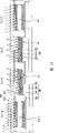
附图说明 Description of drawings
图1是根据本发明的示范性实施例的由用于驱动电泳显示器的方法驱动的电泳显示器的布局图;1 is a layout view of an electrophoretic display driven by a method for driving an electrophoretic display according to an exemplary embodiment of the present invention;
图2是沿线II-II得到的图1所示的电泳显示器的剖面图;Figure 2 is a cross-sectional view of the electrophoretic display shown in Figure 1 obtained along the line II-II;
图3是沿线III-III得到的图1所示的电泳显示器的剖面图,以解释用于分别显示四个像素的图像的方法;3 is a sectional view of the electrophoretic display shown in FIG. 1 taken along line III-III to explain a method for respectively displaying images of four pixels;
图4是展示图3的电泳显示器中的四个相邻像素的图像的图;4 is a diagram showing images of four adjacent pixels in the electrophoretic display of FIG. 3;
图5是展示按时间施加到布置在四个相邻像素中的电泳粒子的驱动电压的图,以解释根据本发明的示范性实施例的用于驱动电泳显示器的方法;5 is a graph showing driving voltages applied to electrophoretic particles arranged in four adjacent pixels in time to explain a method for driving an electrophoretic display according to an exemplary embodiment of the present invention;
图6是展示在图5的第一时间消逝之后的布置在四个像素中的电泳粒子的移动的剖面图;6 is a cross-sectional view showing movement of electrophoretic particles arranged in four pixels after the first time lapse of FIG. 5;
图7是展示在图6的电泳显示器中的四个相邻像素的图像的图;FIG. 7 is a diagram showing images of four adjacent pixels in the electrophoretic display of FIG. 6;
图8是展示在图5的第二时间消逝之后的布置在四个像素中的电泳粒子的移动的剖面图;FIG. 8 is a cross-sectional view showing movement of electrophoretic particles arranged in four pixels after the lapse of the second time of FIG. 5;
图9是展示在图8的电泳显示器中的四个相邻像素的图像的图;9 is a diagram showing images of four adjacent pixels in the electrophoretic display of FIG. 8;
图10是展示在图5的第五时间消逝之后的布置在四个像素中的电泳粒子的移动的剖面图;10 is a cross-sectional view showing movement of electrophoretic particles arranged in four pixels after the lapse of the fifth time of FIG. 5;
图11是展示在图10的电泳显示器中的四个相邻像素的图像的图;Figure 11 is a diagram showing images of four adjacent pixels in the electrophoretic display of Figure 10;
图12是展示在图5的第六时间消逝之后的布置在四个像素中的电泳粒子的移动的剖面图;12 is a cross-sectional view showing movement of electrophoretic particles arranged in four pixels after the lapse of the sixth time of FIG. 5;
图13是展示在图12的电泳显示器中的四个相邻像素的图像的图;Figure 13 is a diagram showing images of four adjacent pixels in the electrophoretic display of Figure 12;
图14是展示在图5的第八时间消逝之后的布置在四个像素中的电泳粒子的移动的剖面图;14 is a cross-sectional view showing movement of electrophoretic particles arranged in four pixels after the elapse of the eighth time of FIG. 5;
图15是展示在图14的电泳显示器中的四个相邻像素的图像的图;Figure 15 is a diagram showing images of four adjacent pixels in the electrophoretic display of Figure 14;
图16是展示在图5的第九时间消逝之后的布置在四个像素中的电泳粒子的移动的剖面图;以及16 is a cross-sectional view showing movement of electrophoretic particles arranged in four pixels after the ninth time lapse of FIG. 5; and
图17是展示在图16的电泳显示器中的四个相邻像素的图像的图。FIG. 17 is a diagram showing images of four adjacent pixels in the electrophoretic display of FIG. 16 .
具体实施方式 Detailed ways
在解释根据本发明的示范性实施例的用于驱动电泳显示器的方法之前,将参考图1到图2详细描述电泳显示器。Before explaining a method for driving an electrophoretic display according to an exemplary embodiment of the present invention, the electrophoretic display will be described in detail with reference to FIGS. 1 to 2 .
图1是由根据本发明的示范性实施例的方法驱动的电泳显示器布局图,以及图2是沿线II-II得到的图1所示的电泳显示器的剖面图。1 is a layout view of an electrophoretic display driven by a method according to an exemplary embodiment of the present invention, and FIG. 2 is a cross-sectional view of the electrophoretic display shown in FIG. 1 taken along line II-II.
电泳显示器包括薄膜晶体管阵列面板100、与薄膜晶体管阵列面板100相对的公共电极面板200、和布置在介于显示面板100和200之间的每个像素A中的电泳层300。The electrophoretic display includes a thin film
参考图1到图2,用于传输栅极信号的多条栅极线121形成在优选由透明玻璃或塑料构成的绝缘基板110上。Referring to FIGS. 1 to 2 , a plurality of
栅极线121大体在横轴方向延伸,以及每条栅极线121包括多个栅极电极124和末端部分129,该末端部分129具有大区域以连接另一层或外部驱动电路。The
由氮化硅SiNx构成的栅极绝缘层140形成于栅极线121上。A
由氢化非晶硅a-Si构成的多个半导体条151形成于栅极绝缘层140上。半导体条151在纵向方向延伸,以及包括朝栅极电极124延伸的多个突起(protrusion)154。同样,半导体条151的宽度在接近栅极线121处变宽,并且相当宽地覆盖栅极线121。A plurality of
在半导体条151上形成多个欧姆接触条和岛161和165,其优选地由诸如高密度掺杂诸如磷的n型杂质的n+氢化非晶硅的材料或硅化物构成。欧姆接触条161包括多个突起163,并且突起163和欧姆接触岛165是在半导体条151的突起154上成对提供的。A plurality of ohmic contact strips and
多条数据线171和多个漏极电极175形成在欧姆接触163和165之上,并且在栅极绝缘层140上。A plurality of
数据线171用来传输数据信号,并且大体在纵向方向延伸从而与栅极线121交叉。每条数据线171包括朝栅极电极124延伸和以“J”形弯曲的多个源级电极173、以及具有大区域从而连接到另一层或外部驱动电路的末端部分179。源级电极173和漏极电极175对彼此分离并且布置在栅极电极124的相反侧。The
半导体条151的栅极电极124、源级电极173、漏极电极175和突起154形成薄膜晶体管(TFT),并且薄膜晶体管的沟道提供给介于源级电极173和漏极电极175之间的突起154。The
在半导体条151下面和数据线171上面以及漏极电极175上面之间插入欧姆接触161和165,而减少其间的接触电阻。
半导体条151包括没有被数据线171和漏极电极175覆盖的多个暴露的部分,诸如位于源级电极173和漏极电极175之间的部分。虽然半导体条151在多数地方比数据线171要窄,但是如上描述的,半导体条151的宽度在接近栅极线处变大,以增强在栅极线121和数据线171之间的绝缘。The
在半导体条151的数据线171、漏极电极175和暴露的部分之上,按单层或多层结构形成钝化层180。钝化层180优选地由具有良好平面特性的光敏有机材料、低电介质绝缘材料(诸如由等离子增强化学汽相淀积(PECVD)形成的a-Si:C:O和a-Si:O:F)、或诸如氮化硅的无机材料构成。例如,如果钝化层180由有机材料构成,则为了防止钝化层180的有机材料与暴露在数据线171和漏极电极175之间的半导体条151接触,可以按照如下方式构造钝化层180:在该有机材料层下面另外形成由SiNx或SiO2构成的绝缘层(未示出)。Over the
钝化层180具有多个接触孔181、185和182,分别暴露栅极线121的末端部分129以及漏极电极175和数据线171的末端部分179。The
在钝化层180之上形成优选地由ITO、IZO或不透光金属构成的多个像素电极190和多个接触助理81和82。A plurality of
像素电极190通过接触孔185物理和电连接到漏极电极175,从而像素电极190从漏极电极175接收数据电压以将数据电压施加到电泳层300。The
接触助理81和82分别通过接触孔181和182连接到栅极线121和数据线171的暴露的末端部分129和179。接触助理81和82保护栅极线121和数据线171的暴露的末端部分,并且补充在暴露的部分和外部设备(诸如驱动集成电路)之间的粘合。The
在钝化层180之上形成包括有机绝缘材料和无机绝缘材料中的至少一个的、布置在像素电极190之间的多个分割区195。分割区195环绕像素电极190的外围以定义在其中填充电泳层300的多个像素A。A plurality of
为了更好理解和方便说明,将像素A展示为四个相邻像素A1、A2、A3和A4,但是可以在薄膜晶体管阵列面板100的水平和垂直方向上重复地提供四个相邻像素A1、A2、A3和A4。For better understanding and convenience of description, the pixel A is shown as four adjacent pixels A1, A2, A3 and A4, but the four adjacent pixels A1, A1, A2, A3 and A4.
下一步,将描述公共电极面板200。Next, the
公共电极面板200与薄膜晶体管阵列面板100相对,并且包括透明绝缘基板210和在绝缘基板210之上形成、并朝向像素电极190的公共电极270。The
公共电极270是由ITO或IZO构成的透明电极,并且将公共电压施加到电泳层300的各个电泳粒子314和316。The
施加公共电压的公共电极270通过与施加数据电压的像素电极190一起向各个电泳粒子314和316施加图像显示电压,来改变电泳粒子314和316的位置,由此显示各种灰度的图像。The
下一步,将描述布置在每个像素A中的电泳层300。Next, the
电泳层300包括:涂白色的和充有负电荷的第一电泳粒子314、涂黑色的和充有正电荷的第二电泳粒子316、和电泳粒子314和316被分散在其中的透明电介质流体(fluid)312。此外,电泳层300可以包括包含电泳粒子314和316以及透明电介质流体312的微胶囊(micro-capsule),并且可以略去在薄膜晶体管阵列面板100中提供的分割区195。同样,可以与以上说明相反,分别以正电荷和负电荷对第一电泳粒子314和第二电泳粒子316充电。The
下一步,将参考图3和图4描述用于根据本发明示范实施例、在电泳显示器的四个像素A的每个中显示不同灰度的图像的方法。Next, a method for displaying images of different grayscales in each of the four pixels A of the electrophoretic display according to an exemplary embodiment of the present invention will be described with reference to FIGS. 3 and 4 .
图3是沿线III-III得到的图1所示的电泳显示器的剖面图,以解释用于分别显示四个像素的图像的方法,以及图4是展示图3的电泳显示器中的四个相邻像素的图像的图。3 is a cross-sectional view of the electrophoretic display shown in FIG. 1 taken along line III-III to explain a method for separately displaying images of four pixels, and FIG. 4 shows four adjacent pixels in the electrophoretic display of FIG. 3 A map of the pixel image.
如图3所示,根据用于施加驱动电压到布置在每个像素A1、A2、A3和A4中的电泳粒子314和316的时间,电泳粒子314和316在像素电极190和公共电极270之间具有四种不同的排列,其中所述驱动电压与在施加到公共电极270的公共电压和施加到像素电极270的数据电压之间的差值对应。As shown in FIG. 3 , according to the time for applying a driving voltage to the
将第一像素A1中的第一电泳粒子314布置为接近公共电极270,将第二电泳粒子316布置为接近像素电极190。因此,从外部入射到第一像素A1上的大多数光被第一电泳粒子314反射。因此,如图4所示,第一像素A1显示具有最高灰度的最亮白色的第三灰度图像。The first
另一方面,第二像素A2中的第一和第二电泳粒子314和316被布置在像素电极190和公共电极270之间,大多数第一电泳粒子314布置成比第二电泳粒子316更接近于公共电极270。因此,从外部入射到第二像素A2上的大量外部光被白色的第一电泳粒子314反射,以及少量外部光被黑色的第二电泳粒子316所吸收。因此,如图4所示,第二像素A2显示比第三灰度图像黑且具有弱灰色的中等灰度的第二灰度图像。On the other hand, the first and second
同样,第三像素A3中的第一和第二电泳粒子314和316被布置在像素电极190和公共电极270之间,但是不同于第二像素A2,大多数第二电泳粒子316布置成比第一电泳粒子314更接近于公共电极270。因此,从外部入射到第三像素A3上的少量外部光被具有白色的第一电泳粒子314反射,以及大量外部光被具有黑色的第二电泳粒子316所吸收。因此,如图4所示,第三像素A3显示比第二灰度图像黑且是中等灰度的硬(hard)灰色的第一灰度图像。Likewise, the first and second
另一方面,第四像素A4中的第一电泳粒子314被布置成接近像素电极190,并且第二电泳粒子316被布置成接近公共电极270。因此,入射在第四像素A4上的大部分的外部光被具有黑色的第二电泳粒子316所吸收。由此,如图4所示,第四像素A4显示最低的灰度且是最黑的颜色的零灰度图像。On the other hand, the first
有可能以与上述四种不同的排列将电泳粒子314和316布置在每个像素A1、A2、A3和A4中。因此,每个像素A1、A2、A3和A4可以显示任意的期望图像。另一方面,如果适当地控制施加用于驱动电泳粒子314和316的驱动电压的时间,则布置在每个像素A1、A2、A3和A4中的电泳粒子314和316可以按超过四种不同位置来排列。因此,每个像素A1、A2、A3和A4可以显示超过四种不同灰度的图像,例如16灰度或32灰度。It is possible to arrange the
现在,将参考图5到图17详细描述根据本发明示范实施例的电泳显示器的驱动方法。Now, a driving method of an electrophoretic display according to an exemplary embodiment of the present invention will be described in detail with reference to FIGS. 5 to 17 .
图5是展示按时间施加到布置在四个相邻像素中的电泳粒子的驱动电压的图,以解释根据本发明的示范性实施例的用于驱动电泳显示器的方法,图6是展示在图5的第一时间消逝之后的布置在四个像素中的电泳粒子的移动的剖面图,以及图7是展示在图6的电泳显示器的四个相邻像素中的图像的图。图8是展示在图5的第二时间消逝之后的布置在四个像素中的电泳粒子的移动的剖面图,以及图9是展示在图8的电泳显示器的四个相邻像素的图像的图,图10是展示在图5的第五时间消逝之后的布置在四个像素中的电泳粒子的移动的剖面图,以及图11是展示在图10的电泳显示器的四个相邻像素的图像的图。图12是展示在图5的第六时间消逝之后的布置在四个像素中的电泳粒子的移动的剖面图,图13是展示在图12的电泳显示器的四个相邻像素的图像的图,图14是展示在图5的第八时间消逝之后的布置在四个像素中的电泳粒子的移动的剖面图,以及图15是展示在图14的电泳显示器的四个相邻像素的图像的图。图16是展示在图5的第九时间消逝之后的布置在四个像素中的电泳粒子的移动的剖面图,以及图17是展示在图16的电泳显示器的四个相邻像素的图像的图。5 is a diagram showing driving voltages applied to electrophoretic particles arranged in four adjacent pixels in time to explain a method for driving an electrophoretic display according to an exemplary embodiment of the present invention, and FIG. 5, and FIG. 7 is a diagram showing images in four adjacent pixels of the electrophoretic display of FIG. 6. 8 is a cross-sectional view showing movement of electrophoretic particles arranged in four pixels after the lapse of the second time of FIG. 5 , and FIG. 9 is a diagram showing images of four adjacent pixels of the electrophoretic display of FIG. 8 , FIG. 10 is a cross-sectional view showing the movement of electrophoretic particles arranged in four pixels after the lapse of the fifth time in FIG. picture. 12 is a cross-sectional view showing movement of electrophoretic particles arranged in four pixels after the lapse of the sixth time in FIG. 5 , and FIG. 13 is a diagram showing images of four adjacent pixels of the electrophoretic display in FIG. 12 , 14 is a cross-sectional view showing movement of electrophoretic particles arranged in four pixels after the elapse of the eighth time of FIG. 5 , and FIG. 15 is a diagram showing images of four adjacent pixels of the electrophoretic display of FIG. 14 . 16 is a cross-sectional view showing movement of electrophoretic particles arranged in four pixels after the ninth time lapse of FIG. 5 , and FIG. 17 is a diagram showing images of four adjacent pixels of the electrophoretic display in FIG. 16 .
各种驱动电压由施加到像素电极的数据电压和施加到公共电极的公共电压之间的差值产生。对于图5,这些电压定义如下:Various driving voltages are generated from the difference between the data voltage applied to the pixel electrode and the common voltage applied to the common electrode. For Figure 5, these voltages are defined as follows:
重置电压是具有负电平的图像显示电压V2,以使得第一电泳粒子314可以克服透明电介质流体312的流体电阻并且向像素电极190移动,以及使得第二电泳粒子316可以克服透明电介质流体312的流体电阻并且向公共电极270移动。The reset voltage is an image display voltage V2 with a negative level, so that the first
重置补偿电压是具有正电平的最后补偿电压V1,以使得第一电泳粒子314可以克服透明电介质流体312的流体电阻并且向公共电极270移动,以及使得第二电泳粒子316可以克服透明电介质流体312的流体电阻并且向像素电极190移动。重置补偿电压具有与重置电压和图像显示电压基本相同的幅度,但是具有相反的极性。The reset compensation voltage is the last compensation voltage V1 having a positive level, so that the first
中等灰度显示电压V1或V2是具有用于显示灰度图像的正或负电平的电压,以使得第一电泳粒子314可以克服透明电介质流体312的流体电阻并且向像素电极190或公共电极270移动,以及使得第二电泳粒子316可以克服透明电介质流体312的流体电阻并且按与第一电泳粒子314的移动方向相反的方向移动。中等灰度显示电压具有与重置电压、图像显示电压、和重置补偿电压、或最后补偿电压基本相同的幅度。The medium grayscale display voltage V1 or V2 is a voltage having a positive or negative level for displaying a grayscale image so that the first
对于图5,定义了施加各种驱动电压V1和V2的时间。每个施加时间T1、T2、T3等由各个阿拉伯数字表示。具有小号码的施加时间并不必须较长,也不必先于具有较大号码的施加时间。For Fig. 5, the times for applying various driving voltages V1 and V2 are defined. Each application time T1, T2, T3, etc. is indicated by respective Arabic numerals. The application time with the small number does not have to be longer, nor does it have to precede the application time with the larger number.
第一时间T1是用来显示零灰度的图像的重置电压的施加时间,其中第一电泳粒子314和第二电泳粒子316分别与图3的第四像素A4中的电泳粒子314和316的移动和布置类似地移动和布置,以使得相应像素是在最低的灰度。The first time T1 is the application time of the reset voltage for displaying an image of zero gray scale, wherein the first
第二时间T2是用来显示第三灰度的图像的重置补偿电压的施加时间,其中,已按照与图3的第四像素A4相同排列的第一电泳粒子314和第二电泳粒子316如图3的第一像素A1一样地移动,以使得相应像素是在最高的灰度。第二时间具有与第一时间T1基本相同的长度。The second time T2 is the application time of the reset compensation voltage for displaying the image of the third gray scale, wherein the first
第五时间T5是用来显示零灰度的图像的图像显示电压的施加时间,其中,已按照与图3的第一像素A1的电泳粒子的相同排列的第一电泳粒子314和第二电泳粒子316移动到如图3的第四像素A4的排列的相同排列,以使得相应像素是在最低的灰度。第五时间具有与第一时间T1基本相同的长度。The fifth time T5 is the application time of the image display voltage for displaying an image of zero gray scale, wherein the first
第三时间T3是用来显示第二灰度的图像的图像显示电压的施加时间,其中,已按照与图3的第一像素A1的排列的相同排列的第一电泳粒子314和第二电泳粒子316移动到如图3的第二像素A2的排列的相同排列,以使得相应像素是在第二灰度。第三时间基本具有大约第五时间T5的1/3长的长度。The third time T3 is the application time of the image display voltage for displaying the image of the second grayscale, in which the first
第四时间T4是用来显示第一灰度的图像的图像显示电压的施加时间,其中,已按照与图3的第一像素A1的排列的相同排列的第一电泳粒子314和第二电泳粒子316移动到如图3的第三像素A3的排列的相同排列,以使得相应像素是在第一灰度。第四时间基本具有大约第五时间T5的2/3长的长度。The fourth time T4 is the application time of the image display voltage for displaying an image of the first gray scale, in which the first
第六时间T6是用来显示第一灰度的图像的具有负电平的中等灰度的图像显示电压的施加时间,其中,按照与图3的第一像素A1的排列的相同排列的第一电泳粒子314和第二电泳粒子316移动到如图3的第二像素A2的排列的相同排列,以使得相应像素是在第一灰度。第六时间基本具有与第三时间T3的相同长度。The sixth time T6 is an application time of an image display voltage of a middle gray scale having a negative level for displaying an image of a first gray scale in which the first electrophoretic voltage in the same arrangement as that of the first pixel A1 of FIG. 3 is applied. The
第七时间T7是具有正电平的中等灰度的图像显示电压的施加时间,其中,已按照与图3的第三像素A3的排列的相同排列的第一电泳粒子314和第二电泳粒子316移动到如图3的第二像素A2的排列的相同排列,以使得相应像素是在第一灰度。第七时间基本具有如第三时间T3的相同长度。The seventh time T7 is the application time of an image display voltage with a positive level of medium gray scale, wherein the first
第八时间T8是具有正电平的中等灰度的图像显示电压的施加时间,其中,已按照与图3的第四像素A4的排列的相同排列的第一电泳粒子314和第二电泳粒子316移动到如图3的第二像素A2的排列的相同排列,以使得相应像素是在第一灰度。第八时间基本具有如第四时间T4的相同长度。The eighth time T8 is the application time of an image display voltage with a positive level of medium gray scale, in which the first
第九时间T9是用来显示第三灰度的图像的最后补偿电压的施加时间,其中,已按照与图3的第四像素A4的排列的相同排列的第一电泳粒子314和第二电泳粒子316移动到如图3的第一像素A1的排列的相同排列,以使得相应像素是在最高的灰度。第九时间基本具有如第三时间T3的相同长度。The ninth time T9 is the application time of the last compensation voltage for displaying an image of the third grayscale, wherein the first
Ta、Tb、Td、Te是不施加各个电压V1和V2的时间间隔。它们可以被任意设置为相同或不同、或可以省略。Ta, Tb, Td, Te are time intervals during which the respective voltages V1 and V2 are not applied. They can be arbitrarily set to be the same or different, or can be omitted.
Tc是不施加各个驱动电压以维持图像的时间间隔,其中通过施加重置补偿电压或图像显示电压已经显示每个相应像素。Tc is a time interval during which the respective driving voltages are not applied to maintain an image in which each corresponding pixel has been displayed by applying the reset compensation voltage or the image display voltage.
如图5所示,在根据本发明的示范性实施例的电泳显示器的驱动方法中,在第一时间T1期间,将重置电压V2施加到全部的第一到第四像素A1、A2、A3和A4。如图6所示,分别布置在全部的第一到第四像素A1、A2、A3和A4中的第一电泳粒子314移动到像素电极190,第二电泳粒子316移动到公共电极270。因此,如图7所示,全部的第一到第四像素A1、A2、A3和A4显示作为最低灰度的零灰度的图像。As shown in FIG. 5, in the driving method of the electrophoretic display according to the exemplary embodiment of the present invention, during the first time T1, the reset voltage V2 is applied to all the first to fourth pixels A1, A2, A3 and A4. As shown in FIG. 6 , the first
接着,如图5所示,在第一时间T1和预定的时间Ta消逝之后的第二时间T2期间,将重置补偿电压V1施加到第一到第四像素A1、A2、A3和A4。如图8所示,第一电泳粒子314朝公共电极270移动。第二电泳粒子316朝像素电极190移动。然后,如图9所示,第一到第四像素A1、A2、A3和A4显示作为最高灰度的第三灰度的图像。因为重置电压V2对第一时间T1积分的值与重置补偿电压V1对第二时间T2(其与施加时间T1具有相同的持续时间)积分的值基本相同,所以每个像素A由重置电压V2刷新并且激发电荷被移除。Next, as shown in FIG. 5 , the reset compensation voltage V1 is applied to the first to fourth pixels A1 , A2 , A3 and A4 during the first time T1 and the second time T2 after the predetermined time Ta elapses. As shown in FIG. 8 , the first
接着,如图5所示,在第二时间T2和预定的时间Tb消逝之后的第三时间到第五时间T3、T4、和T5期间,将图像显示电压V2施加到第二到第四像素A2、A3和A4以显示期望图像。此时,不将图像显示电压V2施加到第一像素A1。Next, as shown in FIG. 5, the image display voltage V2 is applied to the second to fourth pixels A2 during the third time to the fifth time T3, T4, and T5 after the elapse of the second time T2 and the predetermined time Tb , A3 and A4 to display the desired image. At this time, the image display voltage V2 is not applied to the first pixel A1.
因此,分别布置在第一到第四像素A1、A2、A3和A4中的第一电泳粒子314和第二电泳粒子316排列为如图10所示。如图11所示,第一像素A1显示作为最高灰度的第三灰度的图像,并且第二像素A2显示比第三灰度要暗的第二灰度的图像。同样,第三像素A3显示比第二灰度要暗的第一灰度的图像,以及第四像素A4显示作为最低灰度的零灰度图像。Accordingly, the first
在本发明的示范实施例中,为了便于解释,第一到第四像素A1、A2、A3和A4分别显示第三灰度、第二灰度、第一灰度、和零灰度的图像。然而,第一到第四像素A1、A2、A3和A4可以显示在零灰度到第三灰度图像中每个灰度的任意的图像。In an exemplary embodiment of the present invention, for convenience of explanation, the first to fourth pixels A1, A2, A3, and A4 display images of a third grayscale, a second grayscale, a first grayscale, and a zero grayscale, respectively. However, the first to fourth pixels A1 , A2 , A3 , and A4 may display an arbitrary image of each grayscale among zero grayscale to third grayscale images.
在图像维持时间Tc期间,通过施加图像显示电压V2,在第一到第四像素A1、A2、A3和A4的每个中显示期望灰度的图像。During the image maintaining time Tc, an image of a desired grayscale is displayed in each of the first to fourth pixels A1, A2, A3, and A4 by applying the image display voltage V2.
接着,如图5所示,在图像维护时间Tc消逝之后的第六时间T6期间,将具有负电平的中等灰度的显示电压V2施加到第一像素A1。分别在第七时间T7和第八时间T8期间,将具有正电平的中等灰度的显示电压V1施加到第三和第四像素A3和A4。不将具有中等灰度的显示电压施加到第二像素A2。Next, as shown in FIG. 5 , during a sixth time T6 after the elapse of the image maintenance time Tc, the display voltage V2 of a middle gray scale having a negative level is applied to the first pixel A1 . During the seventh time T7 and the eighth time T8, the display voltage V1 having a positive level of a middle gray is applied to the third and fourth pixels A3 and A4, respectively. A display voltage having a middle gray scale is not applied to the second pixel A2.
在第六时间T6消逝之后,分别布置在第一到第四像素A1、A2、A3和A4中的第一电泳粒子314和第二电泳粒子316分别被重新排列成如图12所示。与图10不同,布置在第一像素A1和第四像素A4中的电泳粒子314和316的排列被改变。通过这些排列,如图13所示,第一像素A1和第二像素A2分别显示比第三灰度更暗的第二灰度的图像,以及第三像素A3和第四像素A4显示比第二灰度更暗的第一灰度的图像。也就是说,与图11不同,第一像素A1从第三灰度改变成第二灰度的图像,以及第四像素A4从零灰度改变成第一灰度的图像。After the sixth time T6 elapses, the first
在第八时间T8消逝之后,分别布置在第一到第四像素A1、A2、A3和A4中的第一电泳粒子314和第二电泳粒子316分别被重新排列成如图14所示。即,与图12不同,布置在第三像素A3和第四像素A4中的电泳粒子314和316的排列被改变。通过这些排列,如图15所示,全部第一到第四像素A1、A2、A3和A4显示第二灰度的图像。也就是说,与图13不同,第三像素A3和第四像素A4分别从第一灰度改变成第二灰度的图像。After the eighth time T8 elapses, the first
接着,在第八时间T8和预定的时间Td消逝之后的第九时间T9期间,将最后补偿电压V1施加到第一到第四像素A1、A2、A3和A4。Next, the final compensation voltage V1 is applied to the first to fourth pixels A1, A2, A3, and A4 during the eighth time T8 and the ninth time T9 after the predetermined time Td elapses.
因此,布置在第一到第四像素A1、A2、A3和A4中的电泳粒子314和316被重新排列成如图16所示。即,与图14不同,布置在第一到第四像素A1、A2、A3和A4中的电泳粒子314和316的排列全部被改变。根据这些排列,如图17所示,全部第一到第四像素A1、A2、A3和A4显示第三灰度的图像。也就是说,与图15不同,第一到第四像素A1、A2、A3和A4全部从第二灰度改变成第三灰度。Accordingly, the
根据本发明的示范性实施例的电泳显示器的驱动方法,如图11、图13、图15、和图17所示,通过施加图像显示电压、中等灰度显示电压和最后补偿电压,将第一像素A1、第三像素A3和第四像素A4平滑地改变成与在第二像素A2中显示的第一灰度的图像的相同图像,而不显示翻转的图像。因此,在电泳显示器的驱动过程中,用户的眼睛不会接收到负担(burden)。According to the driving method of the electrophoretic display according to the exemplary embodiment of the present invention, as shown in FIG. 11 , FIG. 13 , FIG. 15 , and FIG. 17 , the first The pixel A1, the third pixel A3, and the fourth pixel A4 smoothly change to the same image as the image of the first grayscale displayed in the second pixel A2 without displaying a flipped image. Therefore, during the driving process of the electrophoretic display, the user's eyes will not receive burden (burden).
同样,在第一像素A1的情况下,负电平的中等灰度显示电压V2在与施加时间对应的第六时间T6内的积分值与最后补偿电压V2在与施加时间对应的第九时间T9内的积分值相同;在第二像素A2的情况下,图像显示电压V2在与施加时间对应的第三时间T3内的积分值与最后补偿电压V2在与施加时间对应的第九时间T9内的积分值相同;在第三像素A3的情况下,图像显示电压V2在与施加时间对应的第四时间T4内的积分值与具有正电平的中等灰度显示电压V1在与施加时间对应的第七时间T7内的积分值和最后补偿电压V2在与施加时间对应的第九时间T9内的积分值的和相同;以及在第四像素A4的情况下,图像显示电压V2在与施加时间对应的第五时间T5内的积分值与具有正电平的中等灰度显示电压V1在与施加时间对应的第八时间T8内的积分值和最后补偿电压V2在与施加时间对应的第九时间T9内的积分值的和相同。Likewise, in the case of the first pixel A1, the integrated value of the negative-level medium grayscale display voltage V2 within the sixth time T6 corresponding to the application time and the final compensation voltage V2 within the ninth time T9 corresponding to the application time In the case of the second pixel A2, the integral value of the image display voltage V2 in the third time T3 corresponding to the application time is the same as the integration of the final compensation voltage V2 in the ninth time T9 corresponding to the application time The values are the same; in the case of the third pixel A3, the integrated value of the image display voltage V2 in the fourth time T4 corresponding to the application time is the same as that of the middle grayscale display voltage V1 having a positive level in the seventh time T4 corresponding to the application time. The sum of the integrated value in the time T7 and the integrated value of the last compensation voltage V2 in the ninth time T9 corresponding to the application time is the same; and in the case of the fourth pixel A4, the image display voltage V2 is in the ninth time T9 corresponding to the application time. The integrated value within the fifth time T5 and the integrated value of the middle gray scale display voltage V1 having a positive level during the eighth time T8 corresponding to the application time and the final compensation voltage V2 within the ninth time T9 corresponding to the application time The sum of integral values is the same.
因此,第一到第四像素A1、A2、A3和A4被从图像显示电压刷新到最后补偿电压,从而消除在施加图像显示电压和中等灰度显示电压的过程中的激发电荷。由此,可以改善电泳显示器的显示性能。Accordingly, the first to fourth pixels A1, A2, A3, and A4 are refreshed from the image display voltage to the final compensation voltage, thereby eliminating excited charges during application of the image display voltage and the middle grayscale display voltage. Thus, the display performance of the electrophoretic display can be improved.
同样,布置在第一到第四像素A1、A2、A3和A4中且通过中等灰度显示电压的施加具有图14的排列的电泳粒子314和316仅在作为短暂时间的第九时间T9期间接收最后补偿电压以移动成图16的排列。因此,在电泳显示器的整个驱动过程中可以提高显示速度。Also, the
另一方面,在预定时间Te消逝之后,为期望图像和补偿驱动再次重复施加中等灰度显示电影和和最后补偿电压,以阻止图像显示电压的余像。On the other hand, after the predetermined time Te elapses, the application of the middle gray scale display film and the final compensation voltage is repeated again for the desired image and compensation drive to prevent afterimage of the image display voltage.
不同于以上描述的本发明的示范实施例,各个驱动电压V1和V2以及对应电压V1和V2的施加时间也可以在满足刷新每个像素A的条件下改变。Unlike the exemplary embodiments of the present invention described above, the respective driving voltages V1 and V2 and the application time of the corresponding voltages V1 and V2 may also be changed under the condition of satisfying the refreshment of each pixel A. Referring to FIG.
同样,不同于根据本发明的示范性实施例的电泳显示器的驱动方法,在第一时间T1期间,可以将具有与重置电压V2相反极性和与重置电压V2相同幅度的重置电压来代替重置电压V2施加到布置在第一到第四像素A1、A2、A3和A4中的电泳粒子314和316,从而第一到第四像素A1、A2、A3和A4可以不显示零灰度而是会显示第三灰度的图像。在这种情况下,每次施加的各个驱动电压V1和V2被改变为具有相反极性和相同幅度的驱动电压。Also, unlike the driving method of the electrophoretic display according to the exemplary embodiment of the present invention, during the first time T1, the reset voltage having the opposite polarity to the reset voltage V2 and the same magnitude as the reset voltage V2 may be applied to Instead of the reset voltage V2 is applied to the
此外,电泳显示器的电泳层300可以仅包括具有黑色的透明电介质流体312和具有白色的电泳粒子314,以及可以通过如本发明的示范实施例中的相同驱动方法获得相同的效果。In addition, the
同样,第一电泳粒子314可以具有红、绿和蓝中的一种颜色而不是白色,以显示电泳显示器的各种颜色的图像。在这种情况下,在每个像素A中,依次分别具有红、绿和蓝颜色中的一种的第一电泳粒子314可以随同具有黑色的第二电泳粒子316被布置在透明电介质流体31中。另一方面,第一电泳粒子314可以具有黄色、洋红色、青色中的一种,而不是红、绿和蓝色。Also, the first
虽然已经连同目前考虑为实用的示范性实施例描述了本发明,但是应当理解,本发明不限于公开的实施例,相反,其意在涵盖包括在所附权利要求书的精神和范围中的各种修改和等价布置。While the invention has been described in connection with what are presently considered to be practical exemplary embodiments, it is to be understood that the invention is not limited to the disclosed embodiments, but on the contrary is intended to cover various aspects included within the spirit and scope of the appended claims. Modifications and equivalent arrangements.
如上所示,根据本发明的用于驱动电泳显示器的方法,在像素电极的刷新过程中平滑地改变图像,以防止余像,从而改善了电泳显示器的显示性能。As shown above, according to the method for driving an electrophoretic display of the present invention, an image is smoothly changed during refreshing of a pixel electrode to prevent afterimages, thereby improving display performance of the electrophoretic display.
对相关申请的交叉引用Cross References to Related Applications
本申请要求2007年9月5日在韩国知识产权局提交的专利申请No.10-2007-0089957的优先权,其全部内容通过引用而被合并于此。This application claims priority from Patent Application No. 10-2007-0089957 filed in the Korean Intellectual Property Office on Sep. 5, 2007, the entire contents of which are hereby incorporated by reference.
Claims (20)
Applications Claiming Priority (2)
| Application Number | Priority Date | Filing Date | Title |
|---|---|---|---|
| KR89957/07 | 2007-09-05 | ||
| KR1020070089957A KR101458912B1 (en) | 2007-09-05 | 2007-09-05 | Method of driving electrophoretic display device |
Publications (1)
| Publication Number | Publication Date |
|---|---|
| CN101383127A true CN101383127A (en) | 2009-03-11 |
Family
ID=40406711
Family Applications (1)
| Application Number | Title | Priority Date | Filing Date |
|---|---|---|---|
| CNA2008101317422A Pending CN101383127A (en) | 2007-09-05 | 2008-06-27 | Method for driving electrophoretic display |
Country Status (3)
| Country | Link |
|---|---|
| US (1) | US8174492B2 (en) |
| KR (1) | KR101458912B1 (en) |
| CN (1) | CN101383127A (en) |
Cited By (3)
| Publication number | Priority date | Publication date | Assignee | Title |
|---|---|---|---|---|
| CN101976548A (en) * | 2010-11-15 | 2011-02-16 | 华映视讯(吴江)有限公司 | Driving method of electronic paper |
| CN106782350A (en) * | 2017-01-04 | 2017-05-31 | 深圳市国华光电科技有限公司 | A kind of method that electrophoretic display device (EPD) weakens ghost border |
| CN109817167A (en) * | 2019-02-26 | 2019-05-28 | 江西兴泰科技有限公司 | It is a kind of to eliminate the drive waveforms adjustment method that heterochromatic particle is remained in three color Electronic Paper module displays |
Families Citing this family (25)
| Publication number | Priority date | Publication date | Assignee | Title |
|---|---|---|---|---|
| KR20050049526A (en) * | 2002-10-10 | 2005-05-25 | 코닌클리케 필립스 일렉트로닉스 엔.브이. | Electrophoretic display panel |
| US8964282B2 (en) | 2012-10-02 | 2015-02-24 | E Ink California, Llc | Color display device |
| US8704756B2 (en) * | 2010-05-26 | 2014-04-22 | Sipix Imaging, Inc. | Color display architecture and driving methods |
| US9116412B2 (en) | 2010-05-26 | 2015-08-25 | E Ink California, Llc | Color display architecture and driving methods |
| KR20120100563A (en) * | 2011-03-04 | 2012-09-12 | 삼성전자주식회사 | Driving method for electrophoresis display device |
| US8786935B2 (en) | 2011-06-02 | 2014-07-22 | Sipix Imaging, Inc. | Color electrophoretic display |
| US9013783B2 (en) | 2011-06-02 | 2015-04-21 | E Ink California, Llc | Color electrophoretic display |
| US8605354B2 (en) | 2011-09-02 | 2013-12-10 | Sipix Imaging, Inc. | Color display devices |
| US8917439B2 (en) | 2012-02-09 | 2014-12-23 | E Ink California, Llc | Shutter mode for color display devices |
| US8797636B2 (en) | 2012-07-17 | 2014-08-05 | Sipix Imaging, Inc. | Light-enhancing structure for electrophoretic display |
| US9360733B2 (en) | 2012-10-02 | 2016-06-07 | E Ink California, Llc | Color display device |
| WO2014172636A1 (en) | 2013-04-18 | 2014-10-23 | Sipix Imaging, Inc. | Color display device |
| WO2014186605A1 (en) | 2013-05-17 | 2014-11-20 | Sipix Imaging, Inc. | Color display device with color filters |
| US9383623B2 (en) | 2013-05-17 | 2016-07-05 | E Ink California, Llc | Color display device |
| CA2912689C (en) | 2013-05-17 | 2019-08-20 | E Ink California, Llc | Color display device |
| TWI534520B (en) | 2013-10-11 | 2016-05-21 | 電子墨水加利福尼亞有限責任公司 | Color display device |
| PL3095007T3 (en) | 2014-01-14 | 2020-10-05 | E Ink California, Llc | Method of driving a color display layer |
| US9541814B2 (en) | 2014-02-19 | 2017-01-10 | E Ink California, Llc | Color display device |
| JP6522881B2 (en) * | 2014-03-14 | 2019-05-29 | イー インク コーポレイション | Display medium drive device, display medium drive program, and display device |
| US20150268531A1 (en) | 2014-03-18 | 2015-09-24 | Sipix Imaging, Inc. | Color display device |
| US10891906B2 (en) | 2014-07-09 | 2021-01-12 | E Ink California, Llc | Color display device and driving methods therefor |
| US10380955B2 (en) | 2014-07-09 | 2019-08-13 | E Ink California, Llc | Color display device and driving methods therefor |
| US10147366B2 (en) | 2014-11-17 | 2018-12-04 | E Ink California, Llc | Methods for driving four particle electrophoretic display |
| US11266832B2 (en) | 2017-11-14 | 2022-03-08 | E Ink California, Llc | Electrophoretic active delivery system including porous conductive electrode layer |
| KR102797900B1 (en) | 2019-11-27 | 2025-04-21 | 이 잉크 코포레이션 | Beneficial agent delivery system comprising microcells having an electro-erosion sealing layer |
Family Cites Families (17)
| Publication number | Priority date | Publication date | Assignee | Title |
|---|---|---|---|---|
| JP4211312B2 (en) * | 2001-08-20 | 2009-01-21 | セイコーエプソン株式会社 | Electrophoresis device, electrophoretic device driving method, electrophoretic device driving circuit, and electronic apparatus |
| EP1512044A1 (en) * | 2002-05-24 | 2005-03-09 | Koninklijke Philips Electronics N.V. | Electrophoretic display device and driving method therefor |
| KR20050024444A (en) | 2002-07-01 | 2005-03-10 | 코닌클리케 필립스 일렉트로닉스 엔.브이. | Electrophoretic display panel |
| WO2004066253A1 (en) * | 2003-01-23 | 2004-08-05 | Koninklijke Philips Electronics N.V. | Driving an electrophoretic display |
| JP2004271609A (en) | 2003-03-05 | 2004-09-30 | Canon Inc | Driving method of display device |
| WO2004090857A1 (en) | 2003-03-31 | 2004-10-21 | E Ink Corporation | Methods for driving bistable electro-optic displays |
| WO2005006296A1 (en) * | 2003-07-11 | 2005-01-20 | Koninklijke Philips Electronics, N.V. | Driving scheme for a bi-stable display with improved greyscale accuracy |
| EP1658603A1 (en) * | 2003-08-22 | 2006-05-24 | Koninklijke Philips Electronics N.V. | Electrophoretic display panel |
| WO2005031689A1 (en) | 2003-09-29 | 2005-04-07 | Koninklijke Philips Electronics, N.V. | A bi-stable display with accurate greyscale and natural image update |
| EP1687801A1 (en) | 2003-11-21 | 2006-08-09 | Koninklijke Philips Electronics N.V. | Method and apparatus for driving an electrophoretic display device with reduced image retention |
| EP1687800A1 (en) | 2003-11-21 | 2006-08-09 | Koninklijke Philips Electronics N.V. | Method and apparatus for reducing edge image retention in an electrophoretic display device |
| US20070273637A1 (en) * | 2004-03-22 | 2007-11-29 | Koninklijke Philips Electronics, N.V. | Rail-Stabilized Driving Scheme With Image Memory For An Electrophoretic Display |
| JP4903367B2 (en) | 2004-03-29 | 2012-03-28 | セイコーエプソン株式会社 | Electrophoretic display device, driving method thereof, and memory display device |
| JP2008523420A (en) * | 2004-12-06 | 2008-07-03 | コーニンクレッカ フィリップス エレクトロニクス エヌ ヴィ | Passive matrix electrophoretic display with reset |
| KR100677217B1 (en) | 2004-12-14 | 2007-02-02 | 엘지전자 주식회사 | E-Paper Reset Method |
| JP4529139B2 (en) | 2005-08-31 | 2010-08-25 | セイコーエプソン株式会社 | Method for driving electrophoresis apparatus, controller for controlling electrophoresis apparatus, electrophoresis apparatus, and electronic apparatus |
| JP5045976B2 (en) | 2005-12-15 | 2012-10-10 | Nltテクノロジー株式会社 | Electrophoretic display device and driving method thereof |
-
2007
- 2007-09-05 KR KR1020070089957A patent/KR101458912B1/en active Active
-
2008
- 2008-05-15 US US12/121,603 patent/US8174492B2/en active Active
- 2008-06-27 CN CNA2008101317422A patent/CN101383127A/en active Pending
Cited By (3)
| Publication number | Priority date | Publication date | Assignee | Title |
|---|---|---|---|---|
| CN101976548A (en) * | 2010-11-15 | 2011-02-16 | 华映视讯(吴江)有限公司 | Driving method of electronic paper |
| CN106782350A (en) * | 2017-01-04 | 2017-05-31 | 深圳市国华光电科技有限公司 | A kind of method that electrophoretic display device (EPD) weakens ghost border |
| CN109817167A (en) * | 2019-02-26 | 2019-05-28 | 江西兴泰科技有限公司 | It is a kind of to eliminate the drive waveforms adjustment method that heterochromatic particle is remained in three color Electronic Paper module displays |
Also Published As
| Publication number | Publication date |
|---|---|
| KR101458912B1 (en) | 2014-11-07 |
| US20090058846A1 (en) | 2009-03-05 |
| KR20090024960A (en) | 2009-03-10 |
| US8174492B2 (en) | 2012-05-08 |
Similar Documents
| Publication | Publication Date | Title |
|---|---|---|
| CN101383127A (en) | Method for driving electrophoretic display | |
| US8508466B2 (en) | Driving method for electrophoretic display | |
| US8593438B2 (en) | Electrophoretic display and electronic device | |
| KR101254227B1 (en) | Display panel | |
| US7952558B2 (en) | Methods for driving electrophoretic display so as to avoid persistent unidirectional current through TFT switches | |
| US8411016B2 (en) | Scanning drive circuit and display device including the same | |
| US8698733B2 (en) | Electrophoretic display and method for driving the same | |
| US20080062159A1 (en) | Electrophoretic display and method for driving thereof | |
| KR20080079383A (en) | Method of driving electrophoretic display | |
| US20070182685A1 (en) | Display device | |
| CN101256743B (en) | Display device, driving method of display device, and electronic apparatus | |
| KR101681643B1 (en) | Electro phoretic display and driving method thereof | |
| JP4839551B2 (en) | Organic EL display device | |
| US20060187164A1 (en) | Liquid crystal display device performing dot inversion and method of driving the same | |
| US10386692B2 (en) | Electrophoretic element and display device | |
| CN103177669B (en) | Display device and display method capable of displaying multiple gray scales | |
| US20030123006A1 (en) | Liquid crystal display device and method of fabricating the same | |
| KR101136348B1 (en) | Array substrate and display apparatus having the same | |
| US11521565B2 (en) | Crosstalk reduction for electro-optic displays | |
| US8558784B2 (en) | Flat panel display | |
| CN110114717A (en) | Liquid crystal display device and its driving method | |
| CN100405200C (en) | Liquid crystal display using dual selection diodes | |
| KR20080034544A (en) | Electrophoresis display |
Legal Events
| Date | Code | Title | Description |
|---|---|---|---|
| C06 | Publication | ||
| PB01 | Publication | ||
| C10 | Entry into substantive examination | ||
| SE01 | Entry into force of request for substantive examination | ||
| ASS | Succession or assignment of patent right |
Owner name: SAMSUNG DISPLAY CO., LTD. Free format text: FORMER OWNER: SAMSUNG ELECTRONICS CO., LTD. Effective date: 20121106 |
|
| C41 | Transfer of patent application or patent right or utility model | ||
| TA01 | Transfer of patent application right |
Effective date of registration: 20121106 Address after: Gyeonggi Do, South Korea Applicant after: Samsung Display Co., Ltd. Address before: Gyeonggi Do, South Korea Applicant before: Samsung Electronics Co., Ltd. |
|
| C12 | Rejection of a patent application after its publication | ||
| RJ01 | Rejection of invention patent application after publication |
Application publication date: 20090311 |