CN101379657B - Antenna device for portable radio communication device and portable radio communication device comprising such antenna device - Google Patents
Antenna device for portable radio communication device and portable radio communication device comprising such antenna device Download PDFInfo
- Publication number
- CN101379657B CN101379657B CN2007800048085A CN200780004808A CN101379657B CN 101379657 B CN101379657 B CN 101379657B CN 2007800048085 A CN2007800048085 A CN 2007800048085A CN 200780004808 A CN200780004808 A CN 200780004808A CN 101379657 B CN101379657 B CN 101379657B
- Authority
- CN
- China
- Prior art keywords
- antenna element
- antenna assembly
- interface unit
- antenna
- flexible
- Prior art date
- Legal status (The legal status is an assumption and is not a legal conclusion. Google has not performed a legal analysis and makes no representation as to the accuracy of the status listed.)
- Expired - Fee Related
Links
Images


Classifications
-
- H—ELECTRICITY
- H01—ELECTRIC ELEMENTS
- H01Q—ANTENNAS, i.e. RADIO AERIALS
- H01Q9/00—Electrically-short antennas having dimensions not more than twice the operating wavelength and consisting of conductive active radiating elements
- H01Q9/04—Resonant antennas
- H01Q9/0407—Substantially flat resonant element parallel to ground plane, e.g. patch antenna
- H01Q9/045—Substantially flat resonant element parallel to ground plane, e.g. patch antenna with particular feeding means
-
- H—ELECTRICITY
- H01—ELECTRIC ELEMENTS
- H01Q—ANTENNAS, i.e. RADIO AERIALS
- H01Q1/00—Details of, or arrangements associated with, antennas
- H01Q1/36—Structural form of radiating elements, e.g. cone, spiral, umbrella; Particular materials used therewith
- H01Q1/38—Structural form of radiating elements, e.g. cone, spiral, umbrella; Particular materials used therewith formed by a conductive layer on an insulating support
-
- H—ELECTRICITY
- H01—ELECTRIC ELEMENTS
- H01Q—ANTENNAS, i.e. RADIO AERIALS
- H01Q1/00—Details of, or arrangements associated with, antennas
- H01Q1/12—Supports; Mounting means
- H01Q1/22—Supports; Mounting means by structural association with other equipment or articles
- H01Q1/24—Supports; Mounting means by structural association with other equipment or articles with receiving set
- H01Q1/241—Supports; Mounting means by structural association with other equipment or articles with receiving set used in mobile communications, e.g. GSM
- H01Q1/242—Supports; Mounting means by structural association with other equipment or articles with receiving set used in mobile communications, e.g. GSM specially adapted for hand-held use
- H01Q1/243—Supports; Mounting means by structural association with other equipment or articles with receiving set used in mobile communications, e.g. GSM specially adapted for hand-held use with built-in antennas
-
- H—ELECTRICITY
- H01—ELECTRIC ELEMENTS
- H01Q—ANTENNAS, i.e. RADIO AERIALS
- H01Q1/00—Details of, or arrangements associated with, antennas
- H01Q1/08—Means for collapsing antennas or parts thereof
- H01Q1/085—Flexible aerials; Whip aerials with a resilient base
-
- H—ELECTRICITY
- H01—ELECTRIC ELEMENTS
- H01Q—ANTENNAS, i.e. RADIO AERIALS
- H01Q1/00—Details of, or arrangements associated with, antennas
- H01Q1/12—Supports; Mounting means
- H01Q1/22—Supports; Mounting means by structural association with other equipment or articles
- H01Q1/24—Supports; Mounting means by structural association with other equipment or articles with receiving set
-
- H—ELECTRICITY
- H05—ELECTRIC TECHNIQUES NOT OTHERWISE PROVIDED FOR
- H05K—PRINTED CIRCUITS; CASINGS OR CONSTRUCTIONAL DETAILS OF ELECTRIC APPARATUS; MANUFACTURE OF ASSEMBLAGES OF ELECTRICAL COMPONENTS
- H05K3/00—Apparatus or processes for manufacturing printed circuits
- H05K3/30—Assembling printed circuits with electric components, e.g. with resistors
- H05K3/32—Assembling printed circuits with electric components, e.g. with resistors electrically connecting electric components or wires to printed circuits
- H05K3/325—Assembling printed circuits with electric components, e.g. with resistors electrically connecting electric components or wires to printed circuits by abutting or pinching; Mechanical auxiliary parts therefor
- H05K3/326—Assembling printed circuits with electric components, e.g. with resistors electrically connecting electric components or wires to printed circuits by abutting or pinching; Mechanical auxiliary parts therefor the printed circuit having integral resilient or deformable parts, e.g. tabs or parts of flexible circuits
Landscapes
- Engineering & Computer Science (AREA)
- Computer Networks & Wireless Communication (AREA)
- Support Of Aerials (AREA)
- Details Of Aerials (AREA)
- Transceivers (AREA)
- Waveguide Aerials (AREA)
Abstract
本发明涉及一种用于诸如移动电话的便携式无线通信设备的天线装置,和包括这种天线装置的便携式无线通信设备。该天线装置的特征在于,第一连接部分(14、15;19、20;22、23、24、25)具有在柔性天线振子(10)和连接器件(11)之间延伸的第一段,而第二连接部分(14、15;19、20;22、23、24、25)具有在柔性天线振子(10)和连接器件(11)之间延伸的第二段,使得延伸的总和是恒定的,而与柔性天线振子(10)在支撑结构(9)上的安装位移无关(图6)。

The invention relates to an antenna device for a portable wireless communication device such as a mobile phone, and a portable wireless communication device comprising such an antenna device. The antenna device is characterized in that a first connecting portion (14, 15; 19, 20; 22, 23, 24, 25) has a first section extending between a flexible antenna element (10) and a connecting device (11), and a second connecting portion (14, 15; 19, 20; 22, 23, 24, 25) has a second section extending between the flexible antenna element (10) and the connecting device (11), so that the sum of the extensions is constant regardless of the mounting displacement of the flexible antenna element (10) on a support structure (9) (Figure 6).
Description
技术领域 technical field
本发明总体上涉及天线装置。具体来讲,本发明涉及一种用于便携式无线通信设备的天线装置。The present invention generally relates to antenna arrangements. In particular, the present invention relates to an antenna arrangement for a portable radio communication device.
背景技术 Background technique
随着便携式无线通信设备(例如移动电话)变得更小,设备内包含的电子部件(例如天线)也需要更小。这些部件之间的电连接是借助连接器来实现的,这些连接器应该在部件之间提供良好和明确的电接触,并且应该对小变化不敏感,这种小变化总是在制造和安装过程中出现。As portable wireless communication devices, such as mobile phones, become smaller, the electronic components contained within the devices, such as antennas, also need to be smaller. The electrical connection between these parts is accomplished by means of connectors which should provide good and well-defined electrical contact between the parts and should be insensitive to small variations which are always present during the manufacturing and installation process appears in .
因此,对于小部件来说,弹性类型或弹簧类型的连接器正变得日益有吸引力。已知这种连接器在部件之间提供可靠的电连接。连接器的弹簧特征提供了明确的接触和灵活性,以避免在制造尺寸并不都完全精确时的公差建立。也需要顺应性来包容相对于平面性的偏离,如大量制造工艺(其中触点焊盘可能不是精确平面的)中普遍存在的情况。Therefore, for small components, spring-type or spring-type connectors are becoming increasingly attractive. Such connectors are known to provide reliable electrical connections between components. The spring feature of the connector provides defined contact and flexibility to avoid tolerance build-up when manufacturing dimensions are not all perfectly precise. Compliance is also required to accommodate deviations from planarity, as is common in high-volume manufacturing processes where contact pads may not be precisely planar.
常规的对微型尺寸电子部件进行电连接的方法是在电子部件与印刷电路板之间插入电连接器,例如被称为Pogo PinTM的弹簧接触器(SLC)。A conventional method of electrically connecting micro-sized electronic components is to insert an electrical connector, such as a spring contact (SLC) known as Pogo Pin ™ , between the electronic component and the printed circuit board.
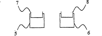
美国专利6,812,899中公开了一种利用SLC将天线振子连接到PCB的天线装置。图1和2中示出了上述美国专利的这种天线装置。该天线装置包括由支撑结构2支撑的天线振子1。支撑结构2包括第一和第二孔径5和6,第一和第二连接部分7和8位于其中。第一和第二连接器件3和4(例如SLC)布置在孔径5和6中,以将连接部分7和8固定在支撑结构2上并确保天线振子1与第一和第二连接器件3和4之间的电接触。US Patent No. 6,812,899 discloses an antenna device using SLC to connect an antenna element to a PCB. Such an antenna arrangement of the aforementioned US patent is shown in FIGS. 1 and 2 . The antenna device includes an antenna element 1 supported by a
图3到5中示出了上述美国专利中公开的天线装置的问题。图3示出了两个孔径5和6,为简便起见彼此相邻安置。当天线振子1安装在支撑结构2上的正确位置时,连接部分7和8具有在天线振子1的平面中延伸的期望长度,如图3中所示。当天线振子1安装在偏离正确位置的位置时,在天线振子1的平面中延伸的连接部分7和8的长度增大或者减小,如图4和5中分别示出的。这种安装偏差导致天线装置的谐振频率/频率偏离了期望的谐振频率,这是我们不愿看到的。Problems with the antenna device disclosed in the above-mentioned US patent are shown in FIGS. 3 to 5 . Figure 3 shows two
发明内容 Contents of the invention
本发明的目的是提供一种使上述问题最小化的天线装置。It is an object of the present invention to provide an antenna arrangement which minimizes the above-mentioned problems.
此外,该目的是通过根据本发明的如所附权利要求中分别限定的天线装置和便携式无线通信设备来实现的。Furthermore, the object is achieved by an antenna arrangement and a portable radio communication device according to the present invention as defined respectively in the appended claims.
通过具有在柔性天线振子和连接器件之间延伸的第一段的柔性天线振子的第一连接部分和具有在柔性天线振子和连接器件之间延伸的第二段的天线振子的第二连接部分,延伸的总和是恒定的,而与柔性天线振子在支撑结构上的安装位移无关。因此,最小化了由柔性天线振子在支撑结构上的安装位移所引起的对天线装置的谐振频率的影响。By having a first connecting portion of the flexible antenna element with a first section extending between the flexible antenna element and the connecting device and a second connecting portion of the antenna element having a second section extending between the flexible antenna element and the connecting device, The sum of the extensions is constant independent of the mounting displacement of the flexible antenna element on the support structure. Therefore, the influence on the resonant frequency of the antenna device caused by the installation displacement of the flexible antenna element on the support structure is minimized.
根据以下描述,本发明的另外特征和优点将显而易见。Additional features and advantages of the invention will be apparent from the description that follows.
附图说明 Description of drawings
根据下面给出的实施方式的详细描述和附图,将更充分地理解本发明,附图仅作为例示而给出,因此并未限制本发明,附图中:The present invention will be more fully understood according to the detailed description of the embodiments given below and the accompanying drawings. The accompanying drawings are provided as illustrations only and therefore do not limit the present invention. In the accompanying drawings:
图1示出了根据现有技术的天线装置;Figure 1 shows an antenna arrangement according to the prior art;
图2示出了图1中示出的天线装置的安装位置的接触器件;Fig. 2 shows the contact means of the installation position of the antenna device shown in Fig. 1;
图3示出了根据现有技术的正确安装的天线振子;Figure 3 shows a properly installed antenna element according to the prior art;
图4示出了根据现有技术的未正确安装的天线振子;Figure 4 shows an incorrectly installed antenna element according to the prior art;
图5示出了根据现有技术的未正确安装的天线振子;Figure 5 shows an incorrectly installed antenna element according to the prior art;
图6示出了根据本发明第一实施方式的天线装置;Fig. 6 shows an antenna device according to a first embodiment of the present invention;
图7a到b示出了根据本发明第一实施方式安装在期望位置上的天线振子;Figures 7a to b show an antenna element installed at a desired location according to a first embodiment of the present invention;
图8a到b示出了根据本发明第一实施方式偏离期望位置安装的天线振子;Figures 8a to b show antenna elements mounted off a desired position according to a first embodiment of the invention;
图9a到d示出了根据本发明的天线振子的连接部分的不同形状;Figures 9a to d show different shapes of the connection part of the antenna element according to the invention;
图10示出了具有两个连接部分的天线振子的正态分布与具有单个连接部分的天线振子的正态分布的比较;Figure 10 shows a comparison of the normal distribution of an antenna element with two connecting parts and the normal distribution of an antenna element having a single connecting part;
图11示出了根据本发明第二实施方式的孔径的截面图;Figure 11 shows a cross-sectional view of an aperture according to a second embodiment of the invention;
图12示出了根据本发明第二实施方式未经连接器件而安装在期望位置上的天线振子;FIG. 12 shows an antenna element installed at a desired position without a connecting device according to a second embodiment of the present invention;
图13示出了根据本发明第二实施方式未经连接器件而偏离期望位置安装的天线振子;Fig. 13 shows an antenna element installed away from a desired position without a connecting device according to a second embodiment of the present invention;
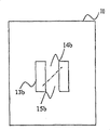
图14示出了根据本发明第三实施方式的天线振子。Fig. 14 shows an antenna element according to a third embodiment of the present invention.
具体实施方式 Detailed ways
在以下描述中,出于说明而不是限制的目的来阐述特定细节,例如特定技术和应用,以提供对于本发明的全面理解。然而,本领域技术人员可以想到的是,本发明可按照与这些特定细节不同的其它实施方式来实践。在其它情况下,省略众所周知的方法和装置的详细描述,从而避免本发明的描述因不必要的细节而难以理解。In the following description, for purposes of illustration and not limitation, specific details are set forth, such as particular techniques and applications, in order to provide a thorough understanding of the present invention. However, it will be apparent to those skilled in the art that the invention may be practiced in other embodiments that depart from these specific details. In other instances, detailed descriptions of well-known methods and apparatus are omitted so as not to obscure the description of the present invention with unnecessary detail.
现在将参照图6到9来描述本发明的第一实施方式。A first embodiment of the present invention will now be described with reference to FIGS. 6 to 9 .
一种用于便携式无线通信设备(例如移动电话、PDA或便携式计算机)的天线装置包括基本上为平面的柔性天线振子10(例如柔性薄膜天线振子)和用于支撑天线振子10的支撑结构9。柔性天线振子10包括两个连接部分14和15,例如用于给天线馈电或使天线接地。连接部分14、15优选地通过柔性天线振子10的冲压(punching out)部分12来提供,从而得到远离天线振子10的其他部分的两个连接部分14、15。An antenna device for a portable wireless communication device (such as a mobile phone, a PDA or a portable computer) includes a substantially planar flexible antenna element 10 (such as a flexible film antenna element) and a
另选的是,连接部分14、15可通过在柔性天线振子10中切下一图案来提供。Alternatively, the
支撑结构9包括用于容纳连接部分14和15的外端的孔径13。该天线装置还包括连接器件11,其优选地具有纵轴,例如SLC或接触片,用于将天线振子10连接到便携式无线通信设备的RF电路(即,馈电或接地)。“纵轴”的表达用于限定孔径穿过的方向。孔径13还用于容纳连接器件11。The
连接器件11被构造用于借助径向力将两个连接部分14和15的外端固定在孔径13中。连接器件11的上端将连接部分14和15的外端都固定在孔径13中并且由此电连接到天线振子10。连接器件11的该上端在优选地与每个连接部分14和15的向下延伸到孔径13中的长度相对应的长度上具有均匀的厚度。连接器件11的另一端优选地在轴向上有弹性,用于连接到便携式无线通信设备的印刷线路板(printed wiring board),从而连接到便携式无线通信设备的RF电路。由于连接器件11的轴向弹性,当这种天线装置被安装到便携式无线通信设备的印刷线路板上时,显著减小了防止连接器件的轴向位移所需的径向力。The connection means 11 is configured to fix the outer ends of the two
孔径13具有正方形截面,使得至少接纳连接部分14和15的侧面是平面的。此外,连接器件11优选地具有圆形截面,使得至少接触连接部分14和15的部分具有圆形表面。这样,就在连接部分14和15与连接器件11之间实现了明确的接触。The
通过上述结构,这种天线装置很容易就能适应天线装置在例如移动电话的外壳中可占用的空间和印刷线路板上的用于连接到移动电话中的RF电路上的接触位置的要求。支撑结构9很容易就能适于适配特定体积。孔径13容易设置在支撑结构9中的不同位置上,与印刷线路板上的期望接触位置相连接。柔性天线振子10安装在支撑结构9上。连接部分14、15的外端位于孔径13中。连接器件11位于孔径13中,将连接部分14、15的外端固定在孔径13中并且将它们与之电连接。还可在孔径13中设置阻体(stopper),以防止连接器件11被推到孔径13深处,这便利了连接器件11的安装。With the above structure, the antenna device can easily be adapted to the space that the antenna device can occupy in eg a housing of a mobile phone and the contact position on the printed circuit board for connection to the RF circuit in the mobile phone. The
在另选的安装工艺中,连接部分14、15的外端最初可以位于孔径13上方,而不是孔径13中,以便随后通过将连接器件11安置在孔径13中而被安置在孔径13中。In an alternative mounting process, the outer ends of the
然后准备将天线装置安置在例如移动电话的外壳中。当连接器件11是在轴向上有弹性时,不必知道支撑结构9和便携式无线通信设备的印刷电路板上的接触位置之间的精确距离。轴向弹性还降低了将连接器件11维持在孔径13中所需的径向力。The antenna arrangement is then ready to be accommodated eg in the housing of a mobile phone. When the connection means 11 is axially elastic, it is not necessary to know the exact distance between the
连接部分14和15都具有从基本为平面的柔性天线振子10延伸到连接器件11的段,其基本上在由基本为平面的柔性天线振子10所限定的平面中。当基本为平面的柔性天线振子10被安装到支撑结构9的期望位置上时,连接部分14、15的段的延伸从孔径13延伸了相等的量,这在图7中示出。图7是示意图,且不同部分之间的距离被高度放大以示出它们的相对位置。然而,如果基本为平面的柔性天线振子10在支撑结构9上的安装偏离了期望位置,则连接部分14、15将延伸到距离孔径13不同的程度,这在图8中示出。同样,图8也是示意图,且不同部分之间的距离被高度放大以示出它们的相对位置。连接部分14、15在由基本为平面的柔性天线振子10限定的平面中的延伸的总和的电长度将仍与基本为平面的柔性天线振子10安装在期望位置时相同。因此这会减少由于基本为平面的柔性天线振子10相对于支撑结构9的安装位移而造成的扩频。连接部分沿着连接器件11向下延伸到孔径中的量,即连接部分的外部,对于频率来说是无关的,因为连接器件11是孔径中的主要导电元件。Both
连接部分的形状优选地通过上述冲压部分来切割,这种冲压移除了天线振子的某些部分,从而在天线振子内形成了连接部分。在图9a到9d中示出了四种不同形状的连接部分:矩形、三角形以及长和短半切口。图9a中的矩形连接部分的优点在于由于其对称性而易于安装,但是同时连接部分的长度受限于孔径的尺寸。The shape of the connecting portion is preferably cut by the above-mentioned punching which removes parts of the antenna element to form the connecting portion within the antenna element. Four different shapes of connection parts are shown in Figures 9a to 9d: rectangular, triangular, and long and short half-cuts. The advantage of the rectangular connection part in Fig. 9a is that it is easy to install due to its symmetry, but at the same time the length of the connection part is limited by the size of the aperture.
除了作为相比于上述现有技术的改进,本发明最大的优点在于天线仅振子使用一个连接器件,每个连接器件都最小化了由于移位的安装位置引起的频偏。In addition to being an improvement over the above-mentioned prior art, the greatest advantage of the present invention is that only one connecting device is used for the antenna vibrator, and each connecting device minimizes the frequency deviation caused by the shifted installation position.
图10示出了如现有技术的连接到具有单个连接部分的天线振子的连接器件的频偏与如上述的连接到具有两个连接部分的天线振子的连接器件的直方图比较。X轴表示频偏。Y轴表示特定频偏的归一化出现。因此,相比于现有技术中的单个连接部分,由于减少了生产中的废料水平,根据本发明具有两个或更多个连接部分是非常有利的。而且,本发明的设计相比于现有技术来说明显更加健壮。Fig. 10 shows a histogram comparing the frequency deviation of a connection device connected to an antenna element with a single connection part as in the prior art and a connection device connected to an antenna element with two connection parts as described above. The X-axis represents frequency offset. The Y-axis represents the normalized occurrence of a particular frequency offset. Thus, having two or more connecting parts according to the invention is very advantageous due to the reduced waste level in production compared to a single connecting part in the prior art. Furthermore, the design of the present invention is significantly more robust than the prior art.
现在将参照图11到13来描述本发明的第二实施方式。除了以下内容以外,本发明的第二实施方式与上述第一实施方式都是相同的。A second embodiment of the present invention will now be described with reference to FIGS. 11 to 13 . The second embodiment of the present invention is the same as the first embodiment described above except for the following.
孔径16的截面是其间有两个平面部分17的两个弧形部分。平面部分17用于接纳连接部分19和20的部分。因此,连接器件的圆形表面(为了不使图混乱而未示出)压住由平面表面支撑的连接部分19和20。而且,连接器件的圆形表面(未示出)压住孔径16的圆形部分的相应圆形表面。优选的是,基本为平面的柔性天线振子的冲压部分18也是基本为圆形,这提供了频偏的进一步减小。The cross-section of the
现在将参照图14来描述本发明的第三实施方式。除了以下内容以外,本发明的第三实施方式与上述第二实施方式都相同。A third embodiment of the present invention will now be described with reference to FIG. 14 . The third embodiment of the present invention is the same as the above-described second embodiment except for the following.
天线振子10被成形为具有四个连接部分22、23、24和25,用于安装在弧形部分之间有四个平面部分的孔径21中。天线振子10的冲压部分26也基本为圆形。The
另选的是,天线振子可被成形为具有三个或五个或更多个连接部分。此外,以上实施方式的连接部分被例示为关于连接器件对称分布,它们优选也是如此。Alternatively, the antenna element may be shaped to have three or five or more connection portions. Furthermore, the connection portions of the above embodiments are exemplified to be symmetrically distributed with respect to the connection means, and they are preferably also so.
以上实施方式中描述的连接器件例如在天线振子是寄生元件时可用于接地,或者在不需要接地点时例如对折叠单极进行馈电。此外,两个或更多个连接器件可用于天线装置,例如分别用于对天线振子进行馈电和使天线振子接地,或者用于若干馈电点和/或接地点,其中每个连接点都可根据上述本发明来形成。The connection means described in the above embodiments can be used for grounding, for example, when the antenna element is a parasitic element, or for feeding a folded monopole, for example, when no grounding point is required. Furthermore, two or more connecting means can be used for the antenna arrangement, for example for feeding and grounding the antenna element respectively, or for several feeding points and/or grounding points, where each connection point is It can be formed according to the present invention described above.
上面使用的术语柔性薄膜,应当解释为包括导电部分的柔性且薄的材料,例如线或带(band)。The term flexible film, as used above, should be interpreted as a flexible and thin material comprising conductive parts, such as wires or bands.
明显的是,本发明可通过多种方式变化。这种变化不应认为是偏离了所附权利要求所限定的本发明的范围。如对于本领域技术人员来说显而易见的所有这种变化旨在包括在所附权利要求所限定的本发明的范围内。Obviously, the invention can be varied in many ways. Such changes are not to be considered as a departure from the scope of the invention as defined in the appended claims. All such variations as would be obvious to a person skilled in the art are intended to be included within the scope of the invention as defined in the appended claims.
天线振子10被描述为基本为平面。应该理解,天线振子也可采用其它形状,例如凸起形状,而这不会偏离本发明的思想。
Claims (11)
Applications Claiming Priority (4)
| Application Number | Priority Date | Filing Date | Title |
|---|---|---|---|
| SE06002737 | 2006-02-08 | ||
| SE0600273A SE528943C2 (en) | 2006-02-08 | 2006-02-08 | Antenna arrangement for portable radio communication device, e.g. mobile phone, comprises connection device fixating antenna component two connection portions to support structure, where two connection portions have two respective segments |
| SE0600273-7 | 2006-02-08 | ||
| PCT/SE2007/000114 WO2007091954A1 (en) | 2006-02-08 | 2007-02-07 | An antenna arrangement for a portable radio coummunication device, and a portable radio communication device comprising such an antenna arrangement |
Publications (2)
| Publication Number | Publication Date |
|---|---|
| CN101379657A CN101379657A (en) | 2009-03-04 |
| CN101379657B true CN101379657B (en) | 2012-05-30 |
Family
ID=37871948
Family Applications (1)
| Application Number | Title | Priority Date | Filing Date |
|---|---|---|---|
| CN2007800048085A Expired - Fee Related CN101379657B (en) | 2006-02-08 | 2007-02-07 | Antenna device for portable radio communication device and portable radio communication device comprising such antenna device |
Country Status (7)
| Country | Link |
|---|---|
| US (1) | US20090309796A1 (en) |
| EP (1) | EP1984976A1 (en) |
| JP (1) | JP2009526471A (en) |
| KR (1) | KR20080112215A (en) |
| CN (1) | CN101379657B (en) |
| SE (1) | SE528943C2 (en) |
| WO (1) | WO2007091954A1 (en) |
Families Citing this family (3)
| Publication number | Priority date | Publication date | Assignee | Title |
|---|---|---|---|---|
| SE0600548L (en) * | 2006-03-13 | 2007-07-03 | Amc Centurion Ab | Antenna device and portable radio communication device for such an antenna device |
| CN101895007A (en) * | 2009-05-22 | 2010-11-24 | 纬创资通股份有限公司 | Electronic device including antenna module |
| US12038549B2 (en) * | 2016-12-30 | 2024-07-16 | Halliburton Energy Services, Inc. | Tools and methods for reduced mechanical ringing |
Citations (3)
| Publication number | Priority date | Publication date | Assignee | Title |
|---|---|---|---|---|
| CN2377690Y (en) * | 1999-04-29 | 2000-05-10 | 杨志远 | Antenna structure of mobile telephone |
| CN1292158A (en) * | 1998-02-26 | 2001-04-18 | 艾利森公司 | Flexible diversity antenna |
| EP1519441A1 (en) * | 2003-09-29 | 2005-03-30 | YOKOWO Co., Ltd | Antenna structure |
Family Cites Families (4)
| Publication number | Priority date | Publication date | Assignee | Title |
|---|---|---|---|---|
| US6723928B1 (en) * | 1997-09-29 | 2004-04-20 | Molex Incorporated | Terminal pins mounted in flexible substrates |
| SE9903482L (en) * | 1999-09-27 | 2001-03-28 | Allgon Ab | Antenna device |
| SE0101172L (en) * | 2001-04-02 | 2002-10-03 | Allgon Mobile Comm Ab | Antenna device |
| US6808422B2 (en) * | 2003-03-19 | 2004-10-26 | Delphi Technologies, Inc. | Filter insert for an electrical connector assembly |
-
2006
- 2006-02-08 SE SE0600273A patent/SE528943C2/en not_active IP Right Cessation
-
2007
- 2007-02-07 WO PCT/SE2007/000114 patent/WO2007091954A1/en not_active Ceased
- 2007-02-07 US US12/278,615 patent/US20090309796A1/en not_active Abandoned
- 2007-02-07 CN CN2007800048085A patent/CN101379657B/en not_active Expired - Fee Related
- 2007-02-07 KR KR1020087021482A patent/KR20080112215A/en not_active Withdrawn
- 2007-02-07 JP JP2008554190A patent/JP2009526471A/en not_active Ceased
- 2007-02-07 EP EP07709330A patent/EP1984976A1/en not_active Withdrawn
Patent Citations (3)
| Publication number | Priority date | Publication date | Assignee | Title |
|---|---|---|---|---|
| CN1292158A (en) * | 1998-02-26 | 2001-04-18 | 艾利森公司 | Flexible diversity antenna |
| CN2377690Y (en) * | 1999-04-29 | 2000-05-10 | 杨志远 | Antenna structure of mobile telephone |
| EP1519441A1 (en) * | 2003-09-29 | 2005-03-30 | YOKOWO Co., Ltd | Antenna structure |
Also Published As
| Publication number | Publication date |
|---|---|
| SE0600273L (en) | 2007-03-20 |
| JP2009526471A (en) | 2009-07-16 |
| SE528943C2 (en) | 2007-03-20 |
| EP1984976A1 (en) | 2008-10-29 |
| KR20080112215A (en) | 2008-12-24 |
| CN101379657A (en) | 2009-03-04 |
| WO2007091954A1 (en) | 2007-08-16 |
| US20090309796A1 (en) | 2009-12-17 |
Similar Documents
| Publication | Publication Date | Title |
|---|---|---|
| CN1993859B (en) | An antenna arrangement for a portable radio communication device, and a portable radio communication device comprising such and antenna arrangement | |
| US8419463B2 (en) | Coaxial connector | |
| US20150311605A1 (en) | Cable connector assembly for a communication system | |
| US6812899B2 (en) | Antenna arrangement | |
| CN101379657B (en) | Antenna device for portable radio communication device and portable radio communication device comprising such antenna device | |
| US20100238076A1 (en) | Printed antenna with improved mounting structure and electronic apparatus using the same | |
| EP1374335B1 (en) | An antenna arrangement | |
| US20100289719A1 (en) | Antenna | |
| US9502825B2 (en) | Shunt for electrical connector | |
| US20090303151A1 (en) | Low profile gps antenna assembly | |
| KR20170084794A (en) | Antenna Module | |
| US10361486B2 (en) | External antenna and method for manufacturing the same | |
| JP2008219661A (en) | Antenna device | |
| KR101083964B1 (en) | Integrated antenna coupling assembly and antenna contact structure | |
| JP2005203817A (en) | Surface-mounted antenna system and electronic apparatus | |
| KR100597628B1 (en) | A method for mounting a contact element in an antenna arrangement | |
| KR200416001Y1 (en) | Terminal structure of the built-in antenna for mobile terminal | |
| JPWO2009113474A1 (en) | Antenna device | |
| JP2015207804A (en) | Three-dimensionally-shaped antenna | |
| US20060256021A1 (en) | Antenna assembly and electronic device utilizing the same | |
| WO2002047197A2 (en) | Antenna device and portable radio communication apparatus | |
| JP2006287398A (en) | Antenna and antenna element | |
| SE536157C2 (en) | Antenna |
Legal Events
| Date | Code | Title | Description |
|---|---|---|---|
| C06 | Publication | ||
| PB01 | Publication | ||
| C10 | Entry into substantive examination | ||
| SE01 | Entry into force of request for substantive examination | ||
| C14 | Grant of patent or utility model | ||
| GR01 | Patent grant | ||
| CF01 | Termination of patent right due to non-payment of annual fee |
Granted publication date: 20120530 Termination date: 20150207 |
|
| EXPY | Termination of patent right or utility model |