CN101339928B - Inner wire structure and method of semiconductor element package - Google Patents
Inner wire structure and method of semiconductor element package Download PDFInfo
- Publication number
- CN101339928B CN101339928B CN2008101329449A CN200810132944A CN101339928B CN 101339928 B CN101339928 B CN 101339928B CN 2008101329449 A CN2008101329449 A CN 2008101329449A CN 200810132944 A CN200810132944 A CN 200810132944A CN 101339928 B CN101339928 B CN 101339928B
- Authority
- CN
- China
- Prior art keywords
- substrate
- crystal grain
- semiconductor die
- die package
- package structure
- Prior art date
- Legal status (The legal status is an assumption and is not a legal conclusion. Google has not performed a legal analysis and makes no representation as to the accuracy of the status listed.)
- Expired - Fee Related
Links
Images


Classifications
-
- H—ELECTRICITY
- H10—SEMICONDUCTOR DEVICES; ELECTRIC SOLID-STATE DEVICES NOT OTHERWISE PROVIDED FOR
- H10W—GENERIC PACKAGES, INTERCONNECTIONS, CONNECTORS OR OTHER CONSTRUCTIONAL DETAILS OF DEVICES COVERED BY CLASS H10
- H10W70/00—Package substrates; Interposers; Redistribution layers [RDL]
- H10W70/60—Insulating or insulated package substrates; Interposers; Redistribution layers
- H10W70/611—Insulating or insulated package substrates; Interposers; Redistribution layers for connecting multiple chips together
- H10W70/614—Insulating or insulated package substrates; Interposers; Redistribution layers for connecting multiple chips together the multiple chips being integrally enclosed
-
- H—ELECTRICITY
- H10—SEMICONDUCTOR DEVICES; ELECTRIC SOLID-STATE DEVICES NOT OTHERWISE PROVIDED FOR
- H10W—GENERIC PACKAGES, INTERCONNECTIONS, CONNECTORS OR OTHER CONSTRUCTIONAL DETAILS OF DEVICES COVERED BY CLASS H10
- H10W72/00—Interconnections or connectors in packages
-
- H—ELECTRICITY
- H10—SEMICONDUCTOR DEVICES; ELECTRIC SOLID-STATE DEVICES NOT OTHERWISE PROVIDED FOR
- H10W—GENERIC PACKAGES, INTERCONNECTIONS, CONNECTORS OR OTHER CONSTRUCTIONAL DETAILS OF DEVICES COVERED BY CLASS H10
- H10W70/00—Package substrates; Interposers; Redistribution layers [RDL]
- H10W70/01—Manufacture or treatment
- H10W70/05—Manufacture or treatment of insulating or insulated package substrates, or of interposers, or of redistribution layers
- H10W70/08—Manufacture or treatment of insulating or insulated package substrates, or of interposers, or of redistribution layers by depositing layers on the chip or wafer, e.g. "chip-first" RDLs
- H10W70/09—Manufacture or treatment of insulating or insulated package substrates, or of interposers, or of redistribution layers by depositing layers on the chip or wafer, e.g. "chip-first" RDLs extending onto an encapsulation that laterally surrounds the chip or wafer, e.g. fan-out wafer level package [FOWLP] RDLs
-
- H—ELECTRICITY
- H10—SEMICONDUCTOR DEVICES; ELECTRIC SOLID-STATE DEVICES NOT OTHERWISE PROVIDED FOR
- H10W—GENERIC PACKAGES, INTERCONNECTIONS, CONNECTORS OR OTHER CONSTRUCTIONAL DETAILS OF DEVICES COVERED BY CLASS H10
- H10W70/00—Package substrates; Interposers; Redistribution layers [RDL]
- H10W70/01—Manufacture or treatment
- H10W70/05—Manufacture or treatment of insulating or insulated package substrates, or of interposers, or of redistribution layers
- H10W70/093—Connecting or disconnecting other interconnections thereto or therefrom, e.g. connecting bond wires or bumps
-
- H—ELECTRICITY
- H10—SEMICONDUCTOR DEVICES; ELECTRIC SOLID-STATE DEVICES NOT OTHERWISE PROVIDED FOR
- H10W—GENERIC PACKAGES, INTERCONNECTIONS, CONNECTORS OR OTHER CONSTRUCTIONAL DETAILS OF DEVICES COVERED BY CLASS H10
- H10W70/00—Package substrates; Interposers; Redistribution layers [RDL]
- H10W70/60—Insulating or insulated package substrates; Interposers; Redistribution layers
-
- H—ELECTRICITY
- H10—SEMICONDUCTOR DEVICES; ELECTRIC SOLID-STATE DEVICES NOT OTHERWISE PROVIDED FOR
- H10W—GENERIC PACKAGES, INTERCONNECTIONS, CONNECTORS OR OTHER CONSTRUCTIONAL DETAILS OF DEVICES COVERED BY CLASS H10
- H10W72/00—Interconnections or connectors in packages
- H10W72/071—Connecting or disconnecting
- H10W72/073—Connecting or disconnecting of die-attach connectors
- H10W72/07321—Aligning
- H10W72/07323—Active alignment, e.g. using optical alignment using marks or sensors
-
- H—ELECTRICITY
- H10—SEMICONDUCTOR DEVICES; ELECTRIC SOLID-STATE DEVICES NOT OTHERWISE PROVIDED FOR
- H10W—GENERIC PACKAGES, INTERCONNECTIONS, CONNECTORS OR OTHER CONSTRUCTIONAL DETAILS OF DEVICES COVERED BY CLASS H10
- H10W72/00—Interconnections or connectors in packages
- H10W72/071—Connecting or disconnecting
- H10W72/073—Connecting or disconnecting of die-attach connectors
- H10W72/07331—Connecting techniques
- H10W72/07337—Connecting techniques using a polymer adhesive, e.g. an adhesive based on silicone or epoxy
-
- H—ELECTRICITY
- H10—SEMICONDUCTOR DEVICES; ELECTRIC SOLID-STATE DEVICES NOT OTHERWISE PROVIDED FOR
- H10W—GENERIC PACKAGES, INTERCONNECTIONS, CONNECTORS OR OTHER CONSTRUCTIONAL DETAILS OF DEVICES COVERED BY CLASS H10
- H10W72/00—Interconnections or connectors in packages
- H10W72/20—Bump connectors, e.g. solder bumps or copper pillars; Dummy bumps; Thermal bumps
- H10W72/241—Dispositions, e.g. layouts
-
- H—ELECTRICITY
- H10—SEMICONDUCTOR DEVICES; ELECTRIC SOLID-STATE DEVICES NOT OTHERWISE PROVIDED FOR
- H10W—GENERIC PACKAGES, INTERCONNECTIONS, CONNECTORS OR OTHER CONSTRUCTIONAL DETAILS OF DEVICES COVERED BY CLASS H10
- H10W72/00—Interconnections or connectors in packages
- H10W72/30—Die-attach connectors
- H10W72/351—Materials of die-attach connectors
- H10W72/353—Materials of die-attach connectors not comprising solid metals or solid metalloids, e.g. ceramics
- H10W72/354—Materials of die-attach connectors not comprising solid metals or solid metalloids, e.g. ceramics comprising polymers
-
- H—ELECTRICITY
- H10—SEMICONDUCTOR DEVICES; ELECTRIC SOLID-STATE DEVICES NOT OTHERWISE PROVIDED FOR
- H10W—GENERIC PACKAGES, INTERCONNECTIONS, CONNECTORS OR OTHER CONSTRUCTIONAL DETAILS OF DEVICES COVERED BY CLASS H10
- H10W72/00—Interconnections or connectors in packages
- H10W72/90—Bond pads, in general
- H10W72/941—Dispositions of bond pads
- H10W72/9413—Dispositions of bond pads on encapsulations
-
- H—ELECTRICITY
- H10—SEMICONDUCTOR DEVICES; ELECTRIC SOLID-STATE DEVICES NOT OTHERWISE PROVIDED FOR
- H10W—GENERIC PACKAGES, INTERCONNECTIONS, CONNECTORS OR OTHER CONSTRUCTIONAL DETAILS OF DEVICES COVERED BY CLASS H10
- H10W74/00—Encapsulations, e.g. protective coatings
-
- H—ELECTRICITY
- H10—SEMICONDUCTOR DEVICES; ELECTRIC SOLID-STATE DEVICES NOT OTHERWISE PROVIDED FOR
- H10W—GENERIC PACKAGES, INTERCONNECTIONS, CONNECTORS OR OTHER CONSTRUCTIONAL DETAILS OF DEVICES COVERED BY CLASS H10
- H10W74/00—Encapsulations, e.g. protective coatings
- H10W74/10—Encapsulations, e.g. protective coatings characterised by their shape or disposition
- H10W74/15—Encapsulations, e.g. protective coatings characterised by their shape or disposition on active surfaces of flip-chip devices, e.g. underfills
-
- H—ELECTRICITY
- H10—SEMICONDUCTOR DEVICES; ELECTRIC SOLID-STATE DEVICES NOT OTHERWISE PROVIDED FOR
- H10W—GENERIC PACKAGES, INTERCONNECTIONS, CONNECTORS OR OTHER CONSTRUCTIONAL DETAILS OF DEVICES COVERED BY CLASS H10
- H10W90/00—Package configurations
- H10W90/701—Package configurations characterised by the relative positions of pads or connectors relative to package parts
- H10W90/721—Package configurations characterised by the relative positions of pads or connectors relative to package parts of bump connectors
- H10W90/724—Package configurations characterised by the relative positions of pads or connectors relative to package parts of bump connectors between a chip and a stacked insulating package substrate, interposer or RDL
-
- H—ELECTRICITY
- H10—SEMICONDUCTOR DEVICES; ELECTRIC SOLID-STATE DEVICES NOT OTHERWISE PROVIDED FOR
- H10W—GENERIC PACKAGES, INTERCONNECTIONS, CONNECTORS OR OTHER CONSTRUCTIONAL DETAILS OF DEVICES COVERED BY CLASS H10
- H10W90/00—Package configurations
- H10W90/701—Package configurations characterised by the relative positions of pads or connectors relative to package parts
- H10W90/731—Package configurations characterised by the relative positions of pads or connectors relative to package parts of die-attach connectors
- H10W90/734—Package configurations characterised by the relative positions of pads or connectors relative to package parts of die-attach connectors between a chip and a stacked insulating package substrate, interposer or RDL
-
- H—ELECTRICITY
- H10—SEMICONDUCTOR DEVICES; ELECTRIC SOLID-STATE DEVICES NOT OTHERWISE PROVIDED FOR
- H10W—GENERIC PACKAGES, INTERCONNECTIONS, CONNECTORS OR OTHER CONSTRUCTIONAL DETAILS OF DEVICES COVERED BY CLASS H10
- H10W90/00—Package configurations
- H10W90/701—Package configurations characterised by the relative positions of pads or connectors relative to package parts
- H10W90/731—Package configurations characterised by the relative positions of pads or connectors relative to package parts of die-attach connectors
- H10W90/736—Package configurations characterised by the relative positions of pads or connectors relative to package parts of die-attach connectors between a chip and a stacked lead frame, conducting package substrate or heat sink
-
- H—ELECTRICITY
- H10—SEMICONDUCTOR DEVICES; ELECTRIC SOLID-STATE DEVICES NOT OTHERWISE PROVIDED FOR
- H10W—GENERIC PACKAGES, INTERCONNECTIONS, CONNECTORS OR OTHER CONSTRUCTIONAL DETAILS OF DEVICES COVERED BY CLASS H10
- H10W99/00—Subject matter not provided for in other groups of this subclass
Landscapes
- Wire Bonding (AREA)
- Internal Circuitry In Semiconductor Integrated Circuit Devices (AREA)
Abstract
Description
【技术领域】【Technical field】
本发明系有关一种半导体封装,特别是关于一种内联线封装结构。 The present invention relates to a semiconductor package, in particular to an inline packaging structure. the
【背景技术】【Background technique】
高效能集成电路封装已是熟知的技术。工业需求趋使集成电路封装之改善以提升其热及电性效能并降低尺寸及制造成本。在半导体组件领域中,组件之密度持续增加,且体积逐渐减小。高密度组件之封装或交互连接技术的需求亦日益增加,以符合上述情况。一般而言,在覆晶接合方法中,焊锡凸块数组系形成于晶粒表面上。焊锡凸块之形成系利用焊锡化合材料配置于焊锡罩幕层,以产生所需焊锡凸块之图案。晶粒封装之功能包含电源分配、讯号分配、散热、保护及支撑等。由于半导体结构趋向复杂化,而一般传统技术,例如导线架封装、软性封装、刚性封装技术,已无法达成于晶粒上产生具有高密度组件之小型晶粒。 High performance integrated circuit packaging is well known in the art. Industry demands are driving the improvement of integrated circuit packaging to increase its thermal and electrical performance and reduce size and manufacturing costs. In the field of semiconductor components, the density of components continues to increase, and the volume gradually decreases. The demand for packaging or interconnection technology of high-density components is also increasing to meet the above situation. Generally, in the flip-chip bonding method, an array of solder bumps is formed on the surface of the die. Solder bumps are formed by disposing solder compound materials on the solder mask layer to produce the desired pattern of solder bumps. The functions of die package include power distribution, signal distribution, heat dissipation, protection and support, etc. As the semiconductor structure tends to become more complex, general traditional technologies, such as lead frame packaging, flexible packaging, and rigid packaging technologies, have been unable to produce small dies with high-density components on the die. the
通常,BGA封装提供相对于封装表面区域之高密度联线,其包含回旋式讯号路径,传统结构具有高阻抗以及不良散热,因此导致较差散热能力。随着封装密度之增加,将内部组件产生之热导出益形重要。 Typically, BGA packages provide high density wiring relative to the package surface area, which include convoluted signal paths, and conventional structures have high impedance and poor heat dissipation, thus resulting in poor heat dissipation capabilities. As packaging density increases, it becomes increasingly important to dissipate heat generated by internal components. the
覆晶技术为电性连接晶粒至黏合基板(例如印刷电路板)之已知电子讯号连接晶粒技术,晶粒主动面受制于复数之电性耦合(习知技术系位于芯片旁侧)。电讯连接位于覆晶之主动表面上以作为端点,凸块包含锡球以及/或铜、金使得其机械与电性连接于基板之上。位于增层后之锡球具有凸块高度约为50-100微米,晶粒反转配置于基板表面,其凸块对准基板之接触垫,如图1所示。若凸块为锡球,则覆晶上之其将被焊于基板接合垫上,锡接合成本不高,但当基于热机械应力超时产生的材料疲劳时将导致电性阻抗增加以及毁损或孔洞。此外,锡球为锡铅合金组成,以铅为基础之材质将因为会产生有毒物质之释放及进入地下水供应等环保考虑而不再受到欢迎。一般,填充材质被用以降低介于芯片与基板间热膨胀所产生之热应力。 Flip chip technology is a known electronic signal connection die technology that electrically connects a die to an adhesive substrate (such as a printed circuit board). The active surface of the die is subject to multiple electrical couplings (the conventional technology is located on the side of the chip). The telecommunication connections are located on the active surface of the flip chip as terminals, and the bumps include solder balls and/or copper and gold to make the mechanical and electrical connection to the substrate. The solder balls after the build-up have a bump height of about 50-100 microns, and the crystal grains are reversed on the substrate surface, and the bumps are aligned with the contact pads of the substrate, as shown in FIG. 1 . If the bumps are solder balls, they will be soldered to the substrate bonding pads on the flip chip. The cost of tin bonding is not high, but it will lead to increased electrical resistance and damage or holes when the material fatigues due to thermomechanical stress over time. In addition, solder balls are composed of tin-lead alloys, and lead-based materials will no longer be popular due to environmental considerations such as the release of toxic substances and entering groundwater supplies. Generally, the filling material is used to reduce the thermal stress generated by the thermal expansion between the chip and the substrate. the
再者,由于一般封装技术必须先将晶圆上之晶粒分割为个别晶粒,再将晶粒分别封装,因此上述技术之制程十分费时。因为晶粒封装技术与集成电路之发展有密切关联,因此封装技术以及电子组件之尺寸要求越来越高。基于上述之理由,现今之封装技术已逐渐趋向采用球门阵列封装(BGA)、覆晶球门阵列封装、芯片尺寸封装、晶圆级封装之技术。应可理解「晶圆级封装(WLP)」指晶圆上整体封装及所有内联线结构以及其它制程步骤,系于切割为个别芯片(晶粒)之前进行。一般而言,在完成所有配装制程或封装制程之后,由具有复数半导体晶粒之晶圆中将个别半导体封装分离。上述晶圆级封装具有极小之尺寸及良好之电性。 Furthermore, because the general packaging technology must first divide the die on the wafer into individual dies, and then package the dies separately, the process of the above-mentioned technology is very time-consuming. Because the chip packaging technology is closely related to the development of integrated circuits, the requirements for packaging technology and the size of electronic components are getting higher and higher. Based on the above reasons, today's packaging technology has gradually tended to adopt the technologies of goal array packaging (BGA), flip chip goal array packaging, chip size packaging, and wafer level packaging. It should be understood that "Wafer Level Packaging (WLP)" refers to the overall packaging and all interconnect structures and other process steps on a wafer, before dicing into individual chips (die). Generally, individual semiconductor packages are separated from a wafer having a plurality of semiconductor dies after all assembly processes or packaging processes are completed. The above-mentioned wafer-level package has extremely small size and good electrical properties. the
美国第6,271,469号专利揭露具有重分布层(RDL)124之封装结构,如图2所示。此微电子封装包含微电子晶粒102,具有主动面。封装胶体112配置于晶粒102周遭。其中所述之封装胶体至少具有一表面大致上与晶粒主动表面相当平整。第一介电层118配置于封装胶体112与微电子晶粒102主动面之至少一部分之上。至少一导电层124配置于第一介电层118之上。导电层124电性连接微电子晶粒之主动面。第二介电层126以及第三介电层136分别形成于晶粒102之上。介层穿孔132形成于第二介电层126中以利于耦合导线124。接合垫134连接介层穿孔132以及锡球138配置于接合垫上。 US Patent No. 6,271,469 discloses a package structure with a redistribution layer (RDL) 124 , as shown in FIG. 2 . The microelectronic package includes a
上述传统封装结构以及制程技术牵涉过多堆栈介电层层形成于晶粒/基板表面上以构成增层。其不只需要平坦的主动面化以利于增重分布层制程步骤,更须高精度之光微影设备以完成封装步骤,但其于增层制程期间也易于毁损晶粒表面。主要在于欠缺缓冲层界介于硅晶粒与锡球间,因此此架构造成低良率以及可靠度问题。 The conventional packaging structure and process technology described above involve multiple stacked dielectric layers formed on the surface of the die/substrate to form build-up layers. It not only requires a flat active surface to facilitate the process step of the weight distribution layer, but also requires high-precision photolithography equipment to complete the packaging step, but it is also easy to damage the surface of the die during the build-up process. The main reason is that there is a lack of a buffer layer boundary between the silicon die and the solder ball, so this structure causes low yield and reliability problems. the
因此,本发明提供一种具有内连线结构之覆晶结构以克服上述问题以提供较佳组件效能。 Therefore, the present invention provides a flip-chip structure with an interconnection structure to overcome the above-mentioned problems and provide better device performance. the
【发明内容】【Content of invention】
本发明之一目的系在于提供一种半导体组件封装(芯片构装),其具有芯片及导线,提供低成本、高效能以及高可靠度封装。 An object of the present invention is to provide a semiconductor component package (chip package), which has a chip and wires, and provides low-cost, high-efficiency and high-reliability packaging. the
本发明之另一目的系在于提供一种方便、经济的半导体组件封装(芯片构装)之制作方法。 Another object of the present invention is to provide a convenient and economical manufacturing method for semiconductor device packaging (chip assembly). the
本发明揭露一种半导体晶粒封装结构之内联线结构,包含:一基板,具有预先制作之导线电路于其中;一晶粒,具有接触垫于主动表面;一黏合材质,将该晶粒黏合于该基板之上,其中该基板包含通孔贯穿该基板以及该黏合材质;导电材质填充于该通孔以利于连接该接触垫以及该导线电路。 The invention discloses an interconnection structure of a semiconductor chip packaging structure, which includes: a substrate with a prefabricated wire circuit therein; a chip with a contact pad on the active surface; an adhesive material for bonding the chip On the substrate, wherein the substrate includes a through hole passing through the substrate and the adhesive material; the conductive material is filled in the through hole to facilitate connecting the contact pad and the wire circuit. the
上述结构更包含核心黏胶位于该晶粒及基板背面或该黏合材质上,以及导电凸块耦合该导线电路;支撑基板位于该核心黏胶之上。导体层位于该核心黏胶及/或该晶粒背面之上。其中该导体层包含铜箔薄片、溅镀或电镀之铜/镍/金合金。 The above-mentioned structure further includes that the core adhesive is located on the die and the back of the substrate or on the adhesive material, and the conductive bump is coupled to the wire circuit; the supporting substrate is located on the core adhesive. A conductor layer is located on the core paste and/or the backside of the die. Wherein the conductor layer comprises copper foil sheet, sputtered or electroplated copper/nickel/gold alloy. the
其中更包含斜顶结构之封膜单元,位于该晶粒以及基板或该黏合材质之上,斜顶结构之角度约为水平面起30-60度。其中该封膜单元为液态化合物或封胶化合物。 It further includes a sealing film unit with a sloping top structure, which is located on the die and the substrate or the adhesive material. The angle of the sloping top structure is about 30-60 degrees from the horizontal plane. Wherein the sealing unit is a liquid compound or a sealing compound. the
一种形成半导体晶粒封装之内联线结构之方法,包含: A method of forming an interconnection structure in a semiconductor die package, comprising:
提供一基板具有导线电路位于其中; providing a substrate having conductor circuits located therein;
形成黏合材质于基板或晶粒表面(硅晶圆表面)上; Form an adhesive material on the substrate or die surface (silicon wafer surface);
以微对位之置放装置将晶粒配置于该黏合材质之上,以覆晶方式配置; Dispose the die on the adhesive material with a micro-alignment placement device, and arrange it in a flip-chip manner;
形成核心黏胶于该晶粒背面,并填入该晶粒周遭空隙; Form a core paste on the back of the die and fill the voids around the die;
形成通孔于该基板以曝露接触垫,其亦可于基板程序中预制; Form via holes in the substrate to expose contact pads, which can also be prefabricated in the substrate process;
以物理气相沉积或化学气相沉积制作金属种子层于该接触垫上; Forming a metal seed layer on the contact pad by physical vapor deposition or chemical vapor deposition;
形成光阻于该基板/晶粒之上并暴露通孔区域; Form a photoresist on the substrate/die and expose the via area;
以电镀制程制作导电材质于该通孔中,以形成该内联线结构并与该晶粒之接触垫及基板之导线电路耦合。 Making conductive material in the through hole by electroplating process to form the interconnection structure and couple with the contact pad of the chip and the wire circuit of the substrate. the
上述方法更包含形成黏合材质之后热处理该黏合材质;在曝露出金属接触垫之后以干式或湿式清洁该金属接触垫。其中该金属导电包含Ti/Cu,Cu/Au,Cu/Ni/Au或Sn/Ag/Cu。完成内连结 构后更包含去除光阻以及回蚀刻该种子金属层。在此例子中,若无金存在于锡球之金属区上面,则形成之光阻可于物理气相沉积之前保护锡球之金属区。 The above method further includes heat-treating the bonding material after forming the bonding material; dry or wet cleaning the metal contact pad after exposing the metal contact pad. Wherein the metal conductor includes Ti/Cu, Cu/Au, Cu/Ni/Au or Sn/Ag/Cu. After completing the interconnect structure, it further includes removing the photoresist and etching back the seed metal layer. In this example, if no gold is present above the metal region of the solder ball, the photoresist is formed to protect the metal region of the solder ball prior to physical vapor deposition. the
金属种子层包含Ti/Cu,Cu/Au,Cu/Ni/Au或Sn/Ag/Cu。 The metal seed layer contains Ti/Cu, Cu/Au, Cu/Ni/Au or Sn/Ag/Cu. the
【附图说明】【Description of drawings】
图1系为根据先前技术之剖面示意图。 Fig. 1 is a schematic cross-sectional view according to the prior art. the
图2系为根据先前技术之剖面示意图。 Fig. 2 is a schematic cross-sectional view according to the prior art. the
图3系为根据本发明之剖面示意图。 Fig. 3 is a schematic cross-sectional view according to the present invention. the
图4系为根据本发明之剖面示意图。 Fig. 4 is a schematic cross-sectional view according to the present invention. the
图5系为根据本发明之剖面示意图。 Fig. 5 is a schematic cross-sectional view according to the present invention. the
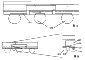
图6系为根据本发明之示意图。 Fig. 6 is a schematic diagram according to the present invention. the
图7至图10系为根据本发明之制程示意图。 7 to 10 are schematic diagrams of the manufacturing process according to the present invention. the
图11系为根据本发明之内连结构剖面示意图。 FIG. 11 is a schematic cross-sectional view of an interconnection structure according to the present invention. the
图中: In the picture:
先前技术 prior art
晶粒102、封装胶体112、第一介电层118、导电层124、第二介电层126、介层穿孔132、接合垫135、第三介电层136、锡球138
本发明 this invention
基板100、晶粒105、黏着材质110、内连线结构115、导线120、导电凸块125、核心黏胶130、支撑基板135、导体层140、封膜单元145
【具体实施方式】【Detailed ways】
本发明将配合其较佳实施例与后附之图式详述于下。应可理解,本发明中之较佳实施例系仅用以说明,而非用以限定本发明。此外,除文中之较佳实施例外,本发明亦可广泛应用于其它实施例,并且本发明并不限定于任何实施例,而应视后附之申请专利范围而定。 The present invention will be described in detail below in conjunction with its preferred embodiments and the accompanying drawings. It should be understood that the preferred embodiments of the present invention are only used for illustration rather than limiting the present invention. In addition, except for the preferred embodiments herein, the present invention can also be widely applied to other embodiments, and the present invention is not limited to any embodiment, but should be determined by the scope of the appended patent application. the
本发明揭露一种半导体封装之结构,包含芯片、导线、以及金属内联线结构,如图3所示。 The present invention discloses a structure of a semiconductor package, including a chip, a wire, and a metal interconnection structure, as shown in FIG. 3 . the
图3系为本发明基板100之截面,基板100可以为金属、玻 璃、陶瓷、塑料、PCB或PI。基板100厚度约为40-70微米,其可为单层或多层(导线电路)基板。晶粒105藉由黏着材质110黏于其上,黏着材质110其具有弹性以吸收热应力。黏着材质110得只覆盖晶粒大小之区域。内联线结构115回填形成于基板100内之通孔,得藉由雷射钻孔制作。内联线结构115耦合到芯片105之预定接触垫102,其材质可为铝垫、铜垫或其它金属垫,其系于形成硅晶圆之重分布层后制作。导线120配至于基板100之底部或上部表面,且耦合到内联线结构115。导电凸块125耦合至导线120之末端。 Fig. 3 is the section of the
图3所示,导线(布线)120形成于基板底下(或内部)。例如,导线120以金、铜、铜镍或类似材质组成。导线120可以藉由电镀技术、涂布或蚀刻方法制作。铜电镀程序持续进行直到所遇之厚度。导线120延伸出承载晶粒之区域,核心黏胶层(corepaste)130系填充且覆盖晶粒105,并形成于基板100或黏着材质110上。可以藉由树脂、化合物、硅胶或环氧树脂构成。 As shown in FIG. 3 , wires (wires) 120 are formed under (or inside) the substrate. For example, the
参阅图4,其显示另一实施例,支撑基板135贴附于核心黏胶层130,以提供封装体之刚性支撑,另一例为导体层140涂布或覆盖于核心黏胶层130上作为散热器。可以藉由银胶粘合铜箔薄片制作、溅镀技术、电镀铜/镍/金制作导体层140,如图5所示。 Referring to FIG. 4 , it shows another embodiment. The support substrate 135 is attached to the core adhesive layer 130 to provide rigid support for the package. Another example is that the
参阅图6,封膜单元145系利用液态化合物或封胶化合物形成以取代核心黏胶层130。晶粒高度约为50-200微米,自封膜单元145至晶粒表面之尺寸大约30-100微米。基板与粘着材质厚度合计大约40-100微米。因此整个封装体之厚度约为大约120-400微米。值得注意者系为封膜单元145具有斜顶,倾斜结构之角度Θ约为30-60度,进而提供较佳之散热路径。 Referring to FIG. 6 , the sealing
参阅图7,基板(圆或矩形)100具有电路形成于其内,黏合材质(较好为具有弹性以吸收热应力,基于热膨胀系数介于基板与硅晶粒不匹配问题)110涂布于基板上,随之热处理(预烘烤)该黏合材质110。晶粒105以微对准装置置放于基板100之上,接着进行最终烘烤。下一步骤为自晶粒105背面印刷或涂布核心黏胶层130。基板135一般则是则是利用面板压合技术(panelbonding)使其与晶粒背面相互结合。随之热处理以形成“panel wafer”,如图8所示。下一步骤为使用雷射穿孔技术凿穿通孔(亦可于面板压合前实施),以及形成金属种子层,随后采用光阻形成通孔及连接至基板电路。随后去除光阻后,使用电镀及蚀刻金属种子层以利于制作内连线结构115。需注意者金属垫可为硅晶圆型态重分布层后之铝垫或其它金属垫,通孔区域非为制作凸块之区域,参图8以及图9。 Referring to FIG. 7, a substrate (round or rectangular) 100 has a circuit formed therein, and an adhesive material (preferably elastic to absorb thermal stress, based on the thermal expansion coefficient between the substrate and the silicon die) 110 is coated on the substrate Then heat treatment (pre-baking) the
随后,凸块置于基板之上,且加以红外线热流步骤以制作终端结构,如图10所示。执行面板级(Panel level)测试以及切割所述(PI)基板以及核心黏胶层以分离“panel wafer”为个别单体。 Subsequently, the bumps are placed on the substrate, and an infrared heat flow step is applied to fabricate the terminal structure, as shown in FIG. 10 . Perform panel level testing and cut the (PI) substrate and core adhesive layer to separate the "panel wafer" into individual monomers. the
图11系为根据本发明之内联线结构之一实施例,集成电路封装之内联机结构包含晶粒105,具有金属接触垫102位于主动表面,黏合材质110位于晶粒105底面,具有预制电路120之基板100用以承载晶粒105,以及通孔形成于基板100及黏合材质110内,导电材质经由通孔结构115耦合至晶粒105之金属接触垫102以联系基板电路120。 11 is an embodiment of the interconnection structure according to the present invention. The interconnection structure of the integrated circuit package includes a
本发明提供简单之制程,无需传统重分布层制程于Panelwafer level中(重分布层意谓导线电路,其预先制作于基板以预防在重分布层制程中损坏芯片)。且本发明无须对准工具,对准图案通常位于基板表面于制作电路过程中。晶粒主动面贴附于基板弹性黏着层,本发明无须底部填充材质,且本发明具有电路之PI基板采大面积面板。且本发明采用简易涂布干式光阻而非湿式光阻,以形成导电材质于通孔区域。晶粒可被封装于其中,只需开孔金属垫区域,因此主动表面受到保护。此架构不但低成本且高良率,且封装体之尺寸极薄(无须锡球高度,硅晶圆易于研磨至非常薄而不会受限于锡球高度因素之考虑)。 The present invention provides a simple manufacturing process without the traditional RDL process at the Panelwafer level (the RDL means a wire circuit, which is prefabricated on the substrate to prevent damage to the chip during the RDL process). And the present invention does not need an alignment tool, and the alignment pattern is usually located on the surface of the substrate during the process of making the circuit. The active surface of the die is attached to the elastic adhesive layer of the substrate. The present invention does not require an underfill material, and the PI substrate with circuits of the present invention adopts a large-area panel. And the present invention adopts simple coating of dry photoresist instead of wet photoresist to form conductive material in the through hole area. The die can be encapsulated in it, only need to open the metal pad area, so the active surface is protected. This structure is not only low cost and high yield, but also the size of the package is extremely thin (no solder ball height is required, silicon wafers can be easily ground to very thin without being limited by solder ball height considerations). the
本发明也藉由采用弹性黏合层做为缓冲层以释放应力,以提供高可靠度结构。填充金属(铜或锡)全覆盖通孔,以强化机械力。其显示于基板Z方向无热应力冲击,其与目前增层技术截然不同。介于PI基板与PCB母板之热膨胀系数相当,其消除热问题,因此,相较于传统技术,本发明有效克服热管理问题。 The present invention also provides a high-reliability structure by using the elastic adhesive layer as a buffer layer to release stress. Filler metal (copper or tin) fully covers the via to enhance mechanical strength. It shows that there is no thermal stress shock in the Z direction of the substrate, which is completely different from the current build-up technology. Because the coefficient of thermal expansion of the PI substrate and the PCB mother board are equivalent, it eliminates the thermal problem. Therefore, compared with the traditional technology, the present invention effectively overcomes the thermal management problem. the
本发明结构包括LGA型态封装(终端垫位于封装周边)及球门阵列(BGA)型态封装。 The structure of the present invention includes LGA type packaging (terminal pads are located on the periphery of the packaging) and ball gate array (BGA) type packaging. the
本发明以较佳实施例说明如上,然其并非用以限定本发明所主张之专利权利范围。其专利保护范围当视后附之权利要求及其等同领域而定。凡熟悉此领域之技艺者,在不脱离本专利精神或范围内,所作之更动或润饰,均属于本发明所揭示精神下所完成之等效改变或设计,且应包含在下述之权利要求内。 The present invention is described above with preferred embodiments, but it is not intended to limit the scope of patent rights claimed by the present invention. The scope of its patent protection shall depend on the appended claims and their equivalent fields. Those who are familiar with the skills in this field, without departing from the spirit or scope of this patent, the changes or modifications are all equivalent changes or designs completed under the spirit disclosed by the present invention, and should be included in the following claims Inside. the
Claims (10)
Applications Claiming Priority (2)
| Application Number | Priority Date | Filing Date | Title |
|---|---|---|---|
| US11/773,993 US20090008777A1 (en) | 2007-07-06 | 2007-07-06 | Inter-connecting structure for semiconductor device package and method of the same |
| US11/773,993 | 2007-07-06 |
Publications (2)
| Publication Number | Publication Date |
|---|---|
| CN101339928A CN101339928A (en) | 2009-01-07 |
| CN101339928B true CN101339928B (en) | 2011-04-06 |
Family
ID=40092772
Family Applications (1)
| Application Number | Title | Priority Date | Filing Date |
|---|---|---|---|
| CN2008101329449A Expired - Fee Related CN101339928B (en) | 2007-07-06 | 2008-07-02 | Inner wire structure and method of semiconductor element package |
Country Status (7)
| Country | Link |
|---|---|
| US (1) | US20090008777A1 (en) |
| JP (1) | JP2009033153A (en) |
| KR (1) | KR20090004775A (en) |
| CN (1) | CN101339928B (en) |
| DE (1) | DE102008031358A1 (en) |
| SG (1) | SG148987A1 (en) |
| TW (1) | TWI344199B (en) |
Families Citing this family (12)
| Publication number | Priority date | Publication date | Assignee | Title |
|---|---|---|---|---|
| US8446243B2 (en) * | 2008-10-31 | 2013-05-21 | Infineon Technologies Austria Ag | Method of constructing inductors and transformers |
| TW201131705A (en) * | 2010-03-03 | 2011-09-16 | Advanced Chip Eng Tech Inc | Conductor package structure and method of the same |
| US20130214418A1 (en) * | 2012-01-12 | 2013-08-22 | King Dragon International Inc. | Semiconductor Device Package with Slanting Structures |
| US20130181227A1 (en) * | 2012-01-12 | 2013-07-18 | King Dragon International Inc. | LED Package with Slanting Structure and Method of the Same |
| CN102867759B (en) * | 2012-08-17 | 2015-04-29 | 日月光半导体制造股份有限公司 | Semiconductor package structure and manufacturing method thereof |
| TWI492344B (en) * | 2013-04-09 | 2015-07-11 | 矽品精密工業股份有限公司 | Semiconductor package and its manufacturing method |
| US9331038B2 (en) | 2013-08-29 | 2016-05-03 | Taiwan Semiconductor Manufacturing Company Ltd. | Semiconductor interconnect structure |
| US9859265B2 (en) * | 2014-06-06 | 2018-01-02 | Taiwan Semiconductor Manufacturing Company, Ltd. | Package structure and methods of forming the same |
| US10043769B2 (en) * | 2015-06-03 | 2018-08-07 | Micron Technology, Inc. | Semiconductor devices including dummy chips |
| KR102492733B1 (en) | 2017-09-29 | 2023-01-27 | 삼성디스플레이 주식회사 | Copper plasma etching method and manufacturing method of display panel |
| US11404365B2 (en) * | 2019-05-07 | 2022-08-02 | International Business Machines Corporation | Direct attachment of capacitors to flip chip dies |
| CN114496986B (en) * | 2022-02-10 | 2025-09-12 | 成都天成电科科技有限公司 | Ultra-wideband wafer-level packaging matching structure |
Family Cites Families (8)
| Publication number | Priority date | Publication date | Assignee | Title |
|---|---|---|---|---|
| US6069407A (en) * | 1998-11-18 | 2000-05-30 | Vlsi Technology, Inc. | BGA package using PCB and tape in a die-up configuration |
| US6181569B1 (en) * | 1999-06-07 | 2001-01-30 | Kishore K. Chakravorty | Low cost chip size package and method of fabricating the same |
| US6271469B1 (en) | 1999-11-12 | 2001-08-07 | Intel Corporation | Direct build-up layer on an encapsulated die package |
| US6569712B2 (en) * | 2001-10-19 | 2003-05-27 | Via Technologies, Inc. | Structure of a ball-grid array package substrate and processes for producing thereof |
| SG115455A1 (en) * | 2002-03-04 | 2005-10-28 | Micron Technology Inc | Methods for assembly and packaging of flip chip configured dice with interposer |
| US20040088855A1 (en) * | 2002-11-11 | 2004-05-13 | Salman Akram | Interposers for chip-scale packages, chip-scale packages including the interposers, test apparatus for effecting wafer-level testing of the chip-scale packages, and methods |
| US7309622B2 (en) * | 2005-02-14 | 2007-12-18 | Stats Chippac Ltd. | Integrated circuit package system with heat sink |
| US20070096285A1 (en) * | 2005-11-02 | 2007-05-03 | Chin-Tien Chiu | Semiconductor die package including construction for preventing delamination and/or cracking of the semiconductor die |
-
2007
- 2007-07-06 US US11/773,993 patent/US20090008777A1/en not_active Abandoned
- 2007-08-27 TW TW096131727A patent/TWI344199B/en active
-
2008
- 2008-07-02 CN CN2008101329449A patent/CN101339928B/en not_active Expired - Fee Related
- 2008-07-04 SG SG200805063-5A patent/SG148987A1/en unknown
- 2008-07-04 DE DE102008031358A patent/DE102008031358A1/en not_active Ceased
- 2008-07-07 KR KR1020080065321A patent/KR20090004775A/en not_active Ceased
- 2008-07-07 JP JP2008176490A patent/JP2009033153A/en not_active Withdrawn
Also Published As
| Publication number | Publication date |
|---|---|
| DE102008031358A1 (en) | 2009-01-08 |
| TW200903763A (en) | 2009-01-16 |
| SG148987A1 (en) | 2009-01-29 |
| US20090008777A1 (en) | 2009-01-08 |
| KR20090004775A (en) | 2009-01-12 |
| TWI344199B (en) | 2011-06-21 |
| CN101339928A (en) | 2009-01-07 |
| JP2009033153A (en) | 2009-02-12 |
Similar Documents
| Publication | Publication Date | Title |
|---|---|---|
| CN101339928B (en) | Inner wire structure and method of semiconductor element package | |
| CN101859752B (en) | Stacking package structure with chip embedded inside and grain having through silicon via and method of manufacturing the same | |
| US8236608B2 (en) | Stacking package structure with chip embedded inside and die having through silicon via and method of the same | |
| TWI352413B (en) | Semiconductor device package with die receiving th | |
| KR101690549B1 (en) | System and method for stacked die embedded chip build-up | |
| TWI533412B (en) | Semiconductor component package structure and method of forming same | |
| US20090166873A1 (en) | Inter-connecting structure for semiconductor device package and method of the same | |
| CN206059367U (en) | Semiconductor device and encapsulated semiconductor device | |
| US20090096098A1 (en) | Inter-connecting structure for semiconductor package and method of the same | |
| EP2207198A2 (en) | Manufacturing method of a semiconductor device | |
| CN102088013B (en) | Substrate structure with die embedded inside and dual build-up layers over both side surfaces and method of the same | |
| CN101232008A (en) | Multi-die packaging and method thereof | |
| CN101252125A (en) | Multiple crystal grain packaging structure with reducing structure and its forming method | |
| US20050176235A1 (en) | Manufacturing method of semiconductor device | |
| JPH11233687A (en) | Semiconductor device having subchip-scale package structure and method of manufacturing the same | |
| TW200828564A (en) | Multi-chip package structure and method of forming the same | |
| TW200830499A (en) | Wafer level package with die receiving through-hole and method of the same | |
| TW200931628A (en) | Stacking die package structure for semiconductor devices and method of the same | |
| US20090096093A1 (en) | Inter-connecting structure for semiconductor package and method of the same | |
| US7498199B2 (en) | Method for fabricating semiconductor package | |
| TW200845343A (en) | Semiconductor device package having multi-chips with side-by-side configuration and the method of the same | |
| CN102034768B (en) | Embedded-dice-inside type substrate structure with redistribution layer covered on both side and method thereof | |
| CN113539844A (en) | Semiconductor device and method of manufacturing the same | |
| CN114038842A (en) | Semiconductor device and method of manufacture | |
| CN113990815A (en) | Silicon-based micro-module plastic package structure and preparation method thereof |
Legal Events
| Date | Code | Title | Description |
|---|---|---|---|
| C06 | Publication | ||
| PB01 | Publication | ||
| C10 | Entry into substantive examination | ||
| SE01 | Entry into force of request for substantive examination | ||
| C14 | Grant of patent or utility model | ||
| GR01 | Patent grant | ||
| CF01 | Termination of patent right due to non-payment of annual fee | ||
| CF01 | Termination of patent right due to non-payment of annual fee |
Granted publication date: 20110406 |