CN101324163A - Cam lock and electric device thereof - Google Patents
Cam lock and electric device thereof Download PDFInfo
- Publication number
- CN101324163A CN101324163A CNA2007100418332A CN200710041833A CN101324163A CN 101324163 A CN101324163 A CN 101324163A CN A2007100418332 A CNA2007100418332 A CN A2007100418332A CN 200710041833 A CN200710041833 A CN 200710041833A CN 101324163 A CN101324163 A CN 101324163A
- Authority
- CN
- China
- Prior art keywords
- cylinder
- lock
- facade
- dead bolt
- lock box
- Prior art date
- Legal status (The legal status is an assumption and is not a legal conclusion. Google has not performed a legal analysis and makes no representation as to the accuracy of the status listed.)
- Granted
Links
Images


Classifications
-
- E—FIXED CONSTRUCTIONS
- E05—LOCKS; KEYS; WINDOW OR DOOR FITTINGS; SAFES
- E05B—LOCKS; ACCESSORIES THEREFOR; HANDCUFFS
- E05B47/00—Operating or controlling locks or other fastening devices by electric or magnetic means
- E05B47/0001—Operating or controlling locks or other fastening devices by electric or magnetic means with electric actuators; Constructional features thereof
- E05B47/0012—Operating or controlling locks or other fastening devices by electric or magnetic means with electric actuators; Constructional features thereof with rotary electromotors
-
- E—FIXED CONSTRUCTIONS
- E05—LOCKS; KEYS; WINDOW OR DOOR FITTINGS; SAFES
- E05B—LOCKS; ACCESSORIES THEREFOR; HANDCUFFS
- E05B47/00—Operating or controlling locks or other fastening devices by electric or magnetic means
- E05B47/06—Controlling mechanically-operated bolts by electro-magnetically-operated detents
- E05B47/0607—Controlling mechanically-operated bolts by electro-magnetically-operated detents the detent moving pivotally or rotatively
-
- E—FIXED CONSTRUCTIONS
- E05—LOCKS; KEYS; WINDOW OR DOOR FITTINGS; SAFES
- E05B—LOCKS; ACCESSORIES THEREFOR; HANDCUFFS
- E05B15/00—Other details of locks; Parts for engagement by bolts of fastening devices
- E05B15/04—Spring arrangements in locks
- E05B2015/0448—Units of springs; Two or more springs working together
-
- E—FIXED CONSTRUCTIONS
- E05—LOCKS; KEYS; WINDOW OR DOOR FITTINGS; SAFES
- E05B—LOCKS; ACCESSORIES THEREFOR; HANDCUFFS
- E05B47/00—Operating or controlling locks or other fastening devices by electric or magnetic means
- E05B47/0001—Operating or controlling locks or other fastening devices by electric or magnetic means with electric actuators; Constructional features thereof
- E05B2047/0014—Constructional features of actuators or power transmissions therefor
- E05B2047/0015—Output elements of actuators
- E05B2047/0016—Output elements of actuators with linearly reciprocating motion
-
- E—FIXED CONSTRUCTIONS
- E05—LOCKS; KEYS; WINDOW OR DOOR FITTINGS; SAFES
- E05B—LOCKS; ACCESSORIES THEREFOR; HANDCUFFS
- E05B47/00—Operating or controlling locks or other fastening devices by electric or magnetic means
- E05B47/0001—Operating or controlling locks or other fastening devices by electric or magnetic means with electric actuators; Constructional features thereof
- E05B2047/0014—Constructional features of actuators or power transmissions therefor
- E05B2047/0018—Details of actuator transmissions
- E05B2047/0023—Nuts or nut-like elements moving along a driven threaded axle
-
- E—FIXED CONSTRUCTIONS
- E05—LOCKS; KEYS; WINDOW OR DOOR FITTINGS; SAFES
- E05B—LOCKS; ACCESSORIES THEREFOR; HANDCUFFS
- E05B47/00—Operating or controlling locks or other fastening devices by electric or magnetic means
- E05B47/0001—Operating or controlling locks or other fastening devices by electric or magnetic means with electric actuators; Constructional features thereof
- E05B2047/0014—Constructional features of actuators or power transmissions therefor
- E05B2047/0018—Details of actuator transmissions
- E05B2047/0026—Clutches, couplings or braking arrangements
- E05B2047/0031—Clutches, couplings or braking arrangements of the elastic type
-
- E—FIXED CONSTRUCTIONS
- E05—LOCKS; KEYS; WINDOW OR DOOR FITTINGS; SAFES
- E05B—LOCKS; ACCESSORIES THEREFOR; HANDCUFFS
- E05B47/00—Operating or controlling locks or other fastening devices by electric or magnetic means
- E05B2047/0093—Operating or controlling locks or other fastening devices by electric or magnetic means including means for preventing manipulation by external shocks, blows or the like
-
- E—FIXED CONSTRUCTIONS
- E05—LOCKS; KEYS; WINDOW OR DOOR FITTINGS; SAFES
- E05B—LOCKS; ACCESSORIES THEREFOR; HANDCUFFS
- E05B65/00—Locks or fastenings for special use
- E05B65/0075—Locks or fastenings for special use for safes, strongrooms, vaults, fire-resisting cabinets or the like
-
- Y—GENERAL TAGGING OF NEW TECHNOLOGICAL DEVELOPMENTS; GENERAL TAGGING OF CROSS-SECTIONAL TECHNOLOGIES SPANNING OVER SEVERAL SECTIONS OF THE IPC; TECHNICAL SUBJECTS COVERED BY FORMER USPC CROSS-REFERENCE ART COLLECTIONS [XRACs] AND DIGESTS
- Y10—TECHNICAL SUBJECTS COVERED BY FORMER USPC
- Y10T—TECHNICAL SUBJECTS COVERED BY FORMER US CLASSIFICATION
- Y10T292/00—Closure fasteners
- Y10T292/08—Bolts
- Y10T292/1043—Swinging
- Y10T292/1075—Operating means
- Y10T292/1077—Cam
-
- Y—GENERAL TAGGING OF NEW TECHNOLOGICAL DEVELOPMENTS; GENERAL TAGGING OF CROSS-SECTIONAL TECHNOLOGIES SPANNING OVER SEVERAL SECTIONS OF THE IPC; TECHNICAL SUBJECTS COVERED BY FORMER USPC CROSS-REFERENCE ART COLLECTIONS [XRACs] AND DIGESTS
- Y10—TECHNICAL SUBJECTS COVERED BY FORMER USPC
- Y10T—TECHNICAL SUBJECTS COVERED BY FORMER US CLASSIFICATION
- Y10T292/00—Closure fasteners
- Y10T292/08—Bolts
- Y10T292/1043—Swinging
- Y10T292/1075—Operating means
- Y10T292/1082—Motor
-
- Y—GENERAL TAGGING OF NEW TECHNOLOGICAL DEVELOPMENTS; GENERAL TAGGING OF CROSS-SECTIONAL TECHNOLOGIES SPANNING OVER SEVERAL SECTIONS OF THE IPC; TECHNICAL SUBJECTS COVERED BY FORMER USPC CROSS-REFERENCE ART COLLECTIONS [XRACs] AND DIGESTS
- Y10—TECHNICAL SUBJECTS COVERED BY FORMER USPC
- Y10T—TECHNICAL SUBJECTS COVERED BY FORMER US CLASSIFICATION
- Y10T70/00—Locks
- Y10T70/70—Operating mechanism
- Y10T70/7051—Using a powered device [e.g., motor]
- Y10T70/7062—Electrical type [e.g., solenoid]
Landscapes
- Lock And Its Accessories (AREA)
Abstract
Description
技术领域 technical field
本发明涉及密码锁,更具体地说,涉及一种保险箱用的电子密码锁。The invention relates to a combination lock, more specifically, to an electronic combination lock for a safe.
背景技术 Background technique
在已有技术中,用于控制保险箱门的密码锁锁体,通常采用直进直出的方形锁舌或楔形锁舌。在常态(锁定状态)下锁舌的收回被限定,而该锁舌又对门执手或门闩形成阻碍,解除对锁舌收回的限定是通过在保险箱密码输入装置上输入正确的密码且被预先设定的程序确认后使一个电动装置动作而得以实现的,而锁舌复位至常态(锁定状态)是由一个复位弹簧作用所致。In the prior art, the combination lock body used to control the safe door usually adopts a straight-in, straight-out square deadbolt or wedge-shaped deadbolt. In the normal state (locked state), the retraction of the deadbolt is limited, and the deadbolt hinders the door handle or the door bolt. The restriction on the retraction of the deadbolt is to enter the correct password on the safe password input device and be preset. After the predetermined program is confirmed, it is realized by actuating an electric device, and the reset of the deadbolt to the normal state (locked state) is caused by the action of a return spring.
专利US5142890,US5134870以及US6786519公开了几种转舌锁结构方案。这上述方案中,锁舌形状为D型(即半圆形或者180度扇形),采用设在锁盒内壁与锁舌之间的拉簧作为锁舌从转进位置(开锁位置)到转出位置(上锁位置)的复位弹簧,对锁舌的锁定是由一个可控的电磁铁(螺线管)的动作部件(铁芯棒)的头部伸出后直接对设在锁舌的一个缺口形成阻碍而实现的。Patents US5142890, US5134870 and US6786519 disclose several rotary cam lock structural solutions. In the above scheme, the shape of the lock tongue is D-shaped (i.e. semicircular or 180-degree fan-shaped), and the tension spring arranged between the inner wall of the lock box and the lock tongue is used as the lock tongue from the turning-in position (unlocked position) to the turning-out position. position (locked position) of the return spring, the locking of the deadbolt is made by the head of the action part (iron mandrel) of a controllable electromagnet (solenoid) stretching out and directly facing one of the deadbolts. This is achieved by the formation of gaps.
上述技术方案存在以下缺点:There is following shortcoming in above-mentioned technical scheme:
当遇到非法强力开锁情况时,很大的外力通过门执手或门闩直接传递到锁舌,而锁舌又将该外力直接传递给电磁铁(螺线管)的动作部件(铁芯棒)的头部,由于锁舌和该动作部件的头部是线接触,应力很集中,容易造成动作部件以及电磁铁(螺线管)或锁体局部的损坏;When encountering illegal strong unlocking, a large external force is directly transmitted to the lock tongue through the door handle or door bolt, and the lock tongue directly transmits the external force to the action part (iron mandrel) of the electromagnet (solenoid). Due to the line contact between the deadbolt and the head of the action part, the stress is very concentrated, which may easily cause damage to the action part and the electromagnet (solenoid) or the lock body;
D型锁舌形状和尺寸较大,所配的复位拉簧也需较大空间伸缩,二者占据较大的锁体内部空间,致使缩小锁体体积或在锁体内增加其他部件十分困难。The shape and size of the D-type dead bolt are relatively large, and the return extension spring that is equipped also needs a large space to expand and contract.
此外,在用于控制保险箱门的密码锁的已有技术中,所采用的电动装置存在如下问题:采用单向(靠弹簧复位)的电磁铁电量消耗大,这一点对使用干电池供电的保险箱密码锁来说是很大的缺点;如果采用双向电磁铁,除了结构复杂外,还需要一个更大的安装空间。In addition, in the prior art for controlling the combination lock of the safe door, the electric device adopted has the following problems: the electric power consumption of the one-way (returning by spring) electromagnet is large, which is very important for the combination lock of the safe using dry batteries. It is a big disadvantage for the lock; if a two-way electromagnet is used, in addition to the complicated structure, a larger installation space is required.
采用马达和将旋转运动转换成直线运动的机构及丝杆丝扣结构,由于锁体内部空间限制,通常使用小体积的高速马达,所使用的丝杆丝扣结构体积也很小,在高速旋转的情况下丝杆和丝扣很难一次对准上扣,容易发生丝杆丝扣卡死造成马达堵转现象,进而损坏丝杆和丝扣或马达。Using a motor, a mechanism that converts rotational motion into linear motion, and a screw and screw structure, due to the limitation of the internal space of the lock body, a small-volume high-speed motor is usually used, and the structure of the screw and screw used is also small in size. Under normal circumstances, it is difficult to align the screw rod and the threaded button at one time, and it is easy to cause the screw rod and threaded button to be stuck, causing the motor to stall, and then damaging the screw rod, screw button or motor.
发明内容 Contents of the invention
本发明的目的旨在提供一种在受到非法强力开锁情况时防止锁体内电动装置直接被破坏的、可将该非法强力合理分解至锁体多个部位的转舌锁;以及提供一种容易使丝杆丝扣上扣且避免马达堵转的电动装置。The purpose of the present invention is to provide a rotary cam lock that prevents the electric device in the lock body from being directly damaged when it is unlocked by illegal force, and can reasonably decompose the illegal force to multiple parts of the lock body; and provides an easy-to-use An electric device that locks the threaded screw and prevents the motor from stalling.
本发明的技术方案包括:Technical scheme of the present invention comprises:
一种转舌锁,它包括:一个具有至少一个缺口120的锁盒10,与该锁盒相配的盒盖80,一个可从缺口120转出至锁定位置和转进至开启位置的锁舌20,一个可控地阻挡锁舌20从锁定位置向开启位置缩进的锁定装置,以及一个可使锁舌20从开启位置复位至锁定位置的弹性元件70,其中:所述锁定装置包括一个挡块30和一个电动装置40,所述挡块具有一个柱体31,该柱体装入设在所述锁盒内对应位置的第一滑槽130内并与之形成滑动配合;在锁舌20处于锁定位置,柱体31的第一边立面32与锁舌20第一立面21平面相对,柱体31的第二边立面33与设在电动装置40上的随动件50头部的第一立面51平面相对,该随动件头部的其它立面与设在锁盒10内的第二滑槽150对应立面平面相对,从而将锁舌20限定在锁定位置;在电动装置40获得允许开锁授权后,其上的随动件50向缩进方向移动使第二滑槽150空出可使柱体31部分进入的空间151,在外力作用下锁舌20向所述开启位置转进,同时施力于柱体31第一立面32使柱体31部分进入已空出的第二滑槽空间151,进而锁舌20可转进至开启位置;所述挡块30上还设有一凹槽35,在锁舌20上与该凹槽对应位置设有一凸柱23,在所述外力撤销后,弹性元件70使锁舌20从所述开启位置向所述锁定位置复位,此时锁舌20上的凸柱23进入挡块30上的凹槽35带动挡块30复位。A rotary cam lock comprising: a
在上述技术方案中,锁舌30为扇形板,其扇形夹角在90度至110度之间,其上设有与设在锁盒10对应位置的轴110滑动配合的轴孔24,锁舌20第二扇形边立面22承受外力,第一扇形边立面21将该外力通过平面接触传递至挡块30上的柱体31的第一边立面32。In the above-mentioned technical solution, the
进一步地,在所述锁盒10和盒盖80与锁舌20对应位置上分别设有第一导轨130和第二导轨83,在盒盖80内还设有与轴110相配的轴孔85,用于对锁舌20的限定和导向。Further, a
在本发明技术方案中,设在挡块30上的柱体31为部分的环形柱体,设在锁盒10对应位置的第一滑槽130由与该环形柱体同心且滑动配合的一个外圆柱面131和一个内圆柱面132构成;柱体31的第一边立面32承受通过与锁舌20第一立面21平面接触传递的外力,该外力通过柱体31的第二边立面33与所述滑动件50头部的第一立面51平面接触传递给滑动件头部,而滑动件头部的第二立面52和第三立面53通过第二滑槽150再将外力传递给锁盒10;所述挡块30有一个设在部分的环形柱体31上部的圆柱体38,设在该圆柱体上的凹槽35为圆弧边开口的扇形凹槽,在锁舌20上与凹槽35对应位置所设凸柱23为圆柱形。In the technical solution of the present invention, the
进一步地,在所述盒盖80设有一装于所述挡块30上圆柱体38的并与该圆柱体滑动配合的圆柱形腔体86,用于对挡块30的进一步定位和导向。Further, the box cover 80 is provided with a cylindrical cavity 86 mounted on the
在本发明技术方案中,所述弹性元件70为一偏压弹簧,其第一圈簧71装于锁盒10的轴110上,第二圈簧72装于设在轴110附近的另一柱轴111上,自由端73卡设在所述锁舌20对应位置上的凹槽25内,以对锁舌施加具有倾向于向锁定位置旋转的力。In the technical solution of the present invention, the elastic element 70 is a bias spring, the
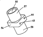
在本发明的技术方案中,还提供一种用于转舌锁或其它保险箱锁的电动装置,它包括:马达41、与该马达同轴连接的丝杆42以及与该丝杆相连接且随马达转动而直线移动的随动件50,其特征在于,所述的随动件50具有一个实心的多面体头部59,该头部可放入设在所述锁盒10内的第二滑槽150内并与之滑动配合,在所述随动件50伸出位置时与所述柱体31的第一边立面32平面相对,该头部59的其他立面与第二滑槽150内对应立面平面相对。In the technical solution of the present invention, there is also provided an electric device for a rotary cam lock or other safe locks, which includes: a motor 41, a
在上述技术方案中,所述随动件50包含一个匣体60,该匣体具有一个实心头部59,其头部第一立面51在所述随动件50伸出位置时与所述柱体31的第一边立面32平面相对,其头部第二立面52和第三立面53分别与第二滑槽150内对应立面平面相对;在匣体60的空腔66内装有一个与丝杆42相配并随该丝杆转动而直线移动的套管56,该套管移动时带动匣体60移动。In the above technical solution, the
进一步地,所述套管56的内孔55是一个与丝杆42外径滑动配合的光孔,在套管56上设有两个与套管内孔55轴向垂直的小孔43、44,两个小孔的直径正好分别穿过一个卡扣61的两条腿63、64,该卡扣穿入上述两个小孔43和44后,其两条腿63和64有效地卡在对应位置的丝杆42螺纹内,丝杆42转动时,该卡扣61和套管56随之作直线移动,进而带动带动匣体60移动。Further, the
还可以在所述套管56两端伸出的两个圆柱57和58上分别套装有弹簧67和68,弹簧67的另一端由匣体60空腔顶端平面62限定,弹簧68的另一端由匣体60空腔66末端平面69限定。
在本发明技术方案中,所述锁盒10设有用于安装微动开关的固定柱18和19,当锁舌20转进至开启位置,正好触碰所述微动开关,使之断开或闭合;还在所述锁盒10设有用于安装控制电路板的固定柱12、13和14,以及用于安装电气接插件的缺口15和缺口16。In the technical solution of the present invention, the
在本发明技术方案中,锁盒10上设置的安装孔77、78和79和盒盖80上设置的安装孔87、88和89具有相同的沉孔,使锁体可以以其锁盒10面与门板接触的方式安装,也可以以其盒盖80面与门板接触的方式安装。In the technical solution of the present invention, the
采用上述技术方案,使得本发明与现有的转舌锁相比,具有以下优点:By adopting the above-mentioned technical scheme, the present invention has the following advantages compared with the existing rotary cam lock:
1.采用挡块及其滑动旋转结构,以面接触的方式承受外力并将所受之力以面接触的方式传递到锁盒,承受和传递外力的电动装置随动件与电动装置的马达轴和丝杆采用弹簧连接,从而防止外力对电动装置的破坏。1. The stopper and its sliding and rotating structure are adopted to bear the external force and transmit the received force to the lock box in the form of surface contact, and the follower of the electric device that bears and transmits the external force and the motor shaft of the electric device It is connected with the screw rod by a spring to prevent damage to the electric device by external force.
2.在该外力通过锁舌向挡块以及通过挡块传递到电动装置的随动件实心头部后再传到锁盒,该过程中外力已至少被分解为两个方向的力,减小了应力集中,从整体上提高了锁体的安全性能。2. After the external force is transmitted to the block through the lock tongue and to the solid head of the follower of the electric device through the block, it is then transmitted to the lock box. During this process, the external force has been decomposed into forces in at least two directions, reducing The stress concentration is reduced, and the safety performance of the lock body is improved as a whole.
3.采用偏压弹簧结构使锁舌的平面尺寸缩小,同时解决了使用拉簧占据空间较大的问题。3. The planar size of the lock tongue is reduced by adopting the bias spring structure, and at the same time, the problem of using a tension spring to occupy a large space is solved.
4.所公开的电动装置,由于采用套管上设置卡扣与丝杆螺纹配合的结构以及采用在套管两端设置导向和缓冲弹簧的结构使丝杆卡死导致马达堵转的问题得以解决。4. In the disclosed electric device, the problem that the screw rod is stuck and the motor stalls due to the structure that the buckle is arranged on the casing and the threaded screw of the screw rod is adopted and the structure that guides and buffer springs are arranged at both ends of the casing is solved .
5.锁体内可设置电路板,电连接器、微动开关等,机电结合紧密,通用性强。锁机构所用零件少,结构简单,易于加工和安装。5. Circuit boards, electrical connectors, micro switches, etc. can be installed in the lock body. The electromechanical combination is tight and the versatility is strong. The lock mechanism uses few parts, has a simple structure, and is easy to process and install.
附图说明 Description of drawings
为了让本领域的技术人员能够进一步了解本发明,下面结合附图予以详细说明。In order to allow those skilled in the art to further understand the present invention, the following will be described in detail in conjunction with the accompanying drawings.
图1是本发明在上锁位置的结构剖面示意图;Fig. 1 is a schematic sectional view of the structure of the present invention in a locked position;
图2是本发明在开锁位置的结构剖面示意图;Fig. 2 is a schematic sectional view of the structure of the present invention in the unlocked position;
图3是本发明的挡块结构示意图;Fig. 3 is a block diagram of the present invention;
图4是本发明的锁舌结构示意图;Fig. 4 is a schematic diagram of the dead bolt structure of the present invention;
图5是本发明的偏压弹簧示意图;Fig. 5 is a schematic diagram of a bias spring of the present invention;
图6是本发明的锁舌、偏压弹簧与锁盒装配关系示意图;Fig. 6 is a schematic diagram of the assembly relationship between the dead bolt, the bias spring and the lock box of the present invention;
图7是本发明的电动装置示意图;Fig. 7 is a schematic diagram of the electric device of the present invention;
图8是本发明的电动装置局部剖面示意图;Fig. 8 is a partial cross-sectional schematic view of the electric device of the present invention;
图9是本发明的匣体结构示意图;Fig. 9 is a schematic diagram of the cassette structure of the present invention;
图10是本发明的丝杆结构示意图;Fig. 10 is a schematic diagram of the screw mandrel structure of the present invention;
图11是本发明图套管结构剖面示意图;Fig. 11 is a schematic cross-sectional view of the sleeve structure of the present invention;
图12是本发明的套管结构示意图;Fig. 12 is a schematic diagram of the sleeve structure of the present invention;
图13是本发明的锁盒结构示意图;Fig. 13 is a schematic structural view of the lock box of the present invention;
图14是本发明的盒盖结构示意图。Fig. 14 is a schematic diagram of the structure of the box cover of the present invention.
具体实施方式 Detailed ways
从图1和图2可以看出扇形锁舌20通过其上的轴孔24装入锁盒内的轴110上,可以在90度左右范围内绕轴旋转。挡块30的环形柱体31的高度和第一滑槽130的高度与锁舌20的平面厚度基本接近,其运动也是在同一个平面内进行的。As can be seen from Fig. 1 and Fig. 2, the sector-shaped
结合图3和图4,在装配时先将锁舌20装入,然后将挡块30的环形柱体31装入锁盒内的第一滑槽130,该滑槽由设在锁盒内的一个半圆柱面131和设在其对面的一个内圆柱壁面132组成,二者之间的距离正好是挡块30的环形柱体31的圆环宽度,但需要保证它们之间的滑动配合关系。挡块30装入后其上的圆柱体38盖在锁舌20之上,在锁定位置时,锁舌20上的复位圆柱23应该位于挡块30的三角形凹槽35内。With reference to Fig. 3 and Fig. 4, when assembling, the
在锁舌20处于锁定位置,也就是电动装置的随动件50处于伸出位置时,随动件的头部59位于第二滑槽150的顶端,限制挡块30的环形柱体31沿图中逆时针方向旋转,由于挡块30第一立面32顶住了锁舌的第一立面21,因此锁舌20被锁定。When the
在锁舌20被锁定的状态下,如果发生非法强力开锁的情况,也就是说,一个很大的外力施加到保险箱门的执手或拉挡机构,该外力首先传至锁舌20的第二立面22,再经锁舌的第一立面21传至挡块30的环形柱体31,再传至随动件的头部59,最后通过锁盒10的第二滑槽150传到锁体。值得注意的是,上述外力的传递均是通过平面接触的方式进行的,并且该外力经过随动件的实心头部59后被分解为分别与头部第二立面52所垂直的以及和头部第三立面53所垂直的二个分力,由此减小了应力集中。此外随动件50与电动装置40之间的驱动连接是弹性的,且只有随动件头部59承受上述外力,丝杆42不承受或承受很少的外力,从而避免了外力直接作用于电动装置而造成的损坏,如此使整个锁体的抗击非法强力开锁的能力得以加强。In the locked state of the
图5示出了复位弹簧70的结构,图6示出了该弹簧装入锁盒10以及与锁舌20的装配关系。该复位弹簧是个偏压弹簧,其大圈簧71套装于轴110上,小圈簧72套装于锁盒内的柱111上,自由端73卡在锁舌20上的凹槽25内,装配好后该偏压弹簧向锁舌20保持施加使其具有倾向于向图1所示的逆时针方向旋转的力。FIG. 5 shows the structure of the return spring 70 , and FIG. 6 shows the assembly of the spring into the
本转舌锁的开启和复位过程如下:The opening and reset process of the turn cam lock is as follows:
当保险箱的输入装置,如键盘、磁卡或者指纹扫描仪等接收到正确的开锁指令后控制电动装置40动作使随动件50移动,解除对锁舌20的锁定。在本实施例中,收到开启指令后给马达41通正向电流,使其正转并带动随动件50沿缩进方向移动,致使使第二滑槽150空出可使柱体31部分进入的空间151。此时若用外力转动保险箱门执手或拉挡机构,在该外力作用下锁舌20克服偏压弹簧70的阻力,向图2所示的顺时针方向转动,此时锁20的第一立面21施力于柱体31的第一立面32,推着柱体31沿图2所示的顺时针方向转过一个角度并使柱体31的一部分进入已空出的第二滑槽空间151,进而锁舌20可转动90度左右至开启位置;上述过程开始时,锁舌上的凸柱23位于挡块上的凹槽35中,在锁舌20转至开启位置同时柱体31转过一个角度,锁舌20上的凸柱23脱离凹槽35。而在锁舌20到达开启位置,凹槽35的扇形开口边正好对准锁舌20复位时其上的凸柱23必经的运动轨迹上。When the input device of safe box, such as keyboard, magnetic card or fingerprint scanner etc. receives correct unlocking instruction, control
当施于执手或拉挡机构的外力撤销后,偏压弹簧70的弹力时使锁舌20从开启位置向锁定位置复位,锁舌向图2所示的逆时针方向转动,此时锁舌20上的凸柱23从挡块30上的凹槽35的扇形开口边进入凹槽35,并施力于凹槽35的另一立面36,从而带动挡块30转回开启时所转过的角度并空出开启时其柱体31占据的第二滑槽150的空间151。锁舌20及挡块30复位后,控制电路给马达41通反向电流使其反转并带动随动件50沿伸出方向移动,直到随动件的实心头部完全进入第二滑槽150的空间151,挡块30再次被限定,锁舌也再次被锁定。When the external force applied to the handle or pull mechanism is removed, the elastic force of the biasing spring 70 causes the
图7示出一种用于转舌锁或其它保险箱所用电动装置,其中马达41是市售的直流电机,该马达可固定在锁盒10上设置的腔体17内,马达轴装入丝杆42上的孔45,由于所传递的力矩很小,可以采用简便的过盈配合装配。匣体60除外轮廓与第二滑槽150滑动配合外,其内框两侧的壁面也要与套管56外侧面滑动配合,当套管56直线移动时,通过施力于套于其上的两个弹簧67、68推动匣体60作直线运动。设置如此的结构,其中一个作用就是当发生冲击性外力时,锁体震动剧烈,有可能使套管56从匣体60中脱出,从而引起故障。而采用上述两个弹簧67、68则可以起到缓冲震动的作用,同时使套管56和匣体60之间的保持一定压力,防止受震动后脱位。Fig. 7 shows a kind of electric device used for turning cam lock or other safes, wherein motor 41 is a commercially available DC motor, and the motor can be fixed in the
设置该两个弹簧的另一个作用是对卡扣61从极限位置(也就是伸出到位和缩进到位)过渡到与丝杆42的螺纹咬扣的位置起导向作用。如图8和图10所示,在丝杆42上设有二个导向槽47和48,当卡扣61的两条腿63、64在位于导向槽47和48中时正好随动件50处于上述的极限位置,无论从锁舌20从锁定位置转到开启为止,还是锁舌20从开启位置复位到锁定位置,卡扣61的两条腿63、64都要从丝杆42上的导向槽47或48过渡到与丝杆螺纹咬扣的位置,而过渡到该位置的必要条件之一就是需要给卡扣61的两条腿63、64一个轴向推力。而设置这两个弹簧67、68就满足了这一条件。从图7、图9和图12可以看出,该二个弹簧67、68分别套在套管56的二个圆柱形肩57、58上并由其中部凸起的矩形体二个端面定位,而弹簧67、68的另一端分别由匣体60腔体的两个端面62和69限定,这样无论在何位置,这二个弹簧67、68都对套管56或者说卡扣61的两条腿63、64保持着一定的轴向推力。从另一方面讲,将传统的丝杆丝扣配合改为由上述的用一个卡扣61的两条腿63、64与丝杆42的螺纹形成配合,一个突出的技术效果就是可以避免因丝杆螺纹和丝扣的咬死而导致马达41被堵转而损坏。上述堵转有两种可能,其一,上扣位置不准或角度偏差发生丝扣咬死;其二,发生其它机械故障,挡块30的柱体31未能复位,致使随动件50向伸出方向移动时遇到障碍。因为在本发明的技术方案中,卡扣61的两条腿63、64与对应的孔43、44之间以及与丝杆30螺纹之间存在一定的间隙,腿63、64还具有一定的弹性,它们与丝杆42螺纹的配合是柔性的,即使发生上述二种情况,卡扣61的两条腿63、64与丝杆42螺纹只会产生打滑现象,即丝杆42在正常转动,但卡扣61和套管56不发生直线移动,因而也不会发生堵转现象,从而避免了马达41因为堵转而发生被损坏的现象。Another function of the two springs is to guide the buckle 61 from the limit position (that is, extending to a position and retracting to a position) to a position where it engages with the screw thread of the
设置该两个弹簧还有一个作用是当锁舌20处于锁定位置,在外力作用下通过挡块30将随动件50阻挡住,而此时控制电路给马达41通正向电流使其转动时,套管56压缩弹簧68,从而保证不发生堵转现象,外力移除后,在弹簧68的作用下随动件50将滑动到开启位置,仍保证了锁的开启;当锁舌20处于开启位置,有外力阻挡不能通过复位弹簧70将锁舌20恢复到锁定位置,挡块30占据了随动件50头部的空间,而此时控制电路给马达41通反向电流使其转动时,丝杠42将压缩弹簧67,从而保证不发生堵转现象,外力移除后,在弹簧67的作用下随动件50将滑动到锁闭位置,保证了锁的关闭。The setting of these two springs also has another function: when the
图13和图14示出本发明的锁盒10和盒盖80的结构,其中,二个柱体18、19用于固定一个微动开关,该开关用于侦测锁舌20是否已处于开启或锁定状态,当锁舌20从锁定位置到达开启位置或者从开启位置复位至锁定位置的过程中,锁舌20会碰触该开关,从而产生一个电信号。在锁盒中还设有用于安装控制电路板的三个柱体12、13、14,以及安装接插件的缺口15、16。Fig. 13 and Fig. 14 show the structure of
锁盒10和盒盖80内分别设置了螺孔11和通孔801,用相配的螺钉可将二者固定。Screw holes 11 and through holes 801 are respectively arranged in the
此外,锁盒10内设置的用于锁舌20转进或转出的缺口120其开口尺寸小于锁舌20的半径尺寸。也就是说,锁舌20不能沿水平方向从缺口120中取出。In addition, the opening size of the
从结构的整体性考虑,还在锁盖80上设置了与锁盒10相配的如下结构:Considering the integrity of the structure, the following structure matching the
用于与锁盒10安装后增强整体强度的二个分别与锁盒10二个缺口120和15相配的舌802和803,装配后二个缺口起到止口定位作用;Two tongues 802 and 803 respectively matched with the two
用于对挡块30的圆柱体38定位的圆柱形腔体86,作为轴孔,腔体86与圆柱体38有着滑动配合关系;The cylindrical cavity 86 used for positioning the
用于对设在锁盒10内的轴110进行定位的圆柱形腔体85,作为轴孔,腔体85与轴110有着滑动配合关系,与设在锁盒10内的导轨130相对应,设置了导轨83,以保证锁舌20可靠灵活的转动;The cylindrical cavity 85 for positioning the
在安装电动装置(直流马达)对应位置设置了二个筋条81和82,用于固定马达;还在第二滑槽150对应位置设置了筋条84,用于限定随动件50。Two ribs 81 and 82 are provided at the corresponding positions for installing the electric device (DC motor) for fixing the motor; ribs 84 are also provided at the corresponding positions of the
在锁盒20上还设置了用于安装防撬重锁装的安装孔75和76,以及在锁盒10和盒盖80上都设置了用于将锁体安装在保险箱门上的安装孔77、78、79和87、88、89。需要说明的是,为了能够提供满足不同的安装需求,上述安装孔都设置了相同的沉孔。如此,不论是将锁盒背面贴着箱门安装锁体,还是将盒盖背面贴着箱门安装锁体,上述设置都能满足。On the
尽管参照本实施例对所公开的涉及一种转舌锁进行了特别描述,但本领域的技术人员将能理解,在不偏离本发明的范围和精神的情况下,可以对它进行形式和细节的种种显而易见的修改。因此,以上描述的实施例是说明性的而不是限制性的,在不脱离本发明的精神和范围的情况下,所有的变化和修改都在本发明的范围之内。Although the disclosed rotary cam lock has been particularly described with reference to the present embodiments, it will be understood by those skilled in the art that changes may be made in form and detail without departing from the scope and spirit of the invention. obvious modifications. Therefore, the embodiments described above are illustrative rather than restrictive, and all changes and modifications are within the scope of the invention without departing from the spirit and scope of the invention.
Claims (12)
Priority Applications (6)
| Application Number | Priority Date | Filing Date | Title |
|---|---|---|---|
| CN2007100418332A CN101324163B (en) | 2007-06-11 | 2007-06-11 | A turn cam lock |
| US12/012,812 US7770944B2 (en) | 2007-06-11 | 2008-02-06 | Lock with a swing bolt and an actuator assembly thereof |
| DE102008008598.7A DE102008008598B4 (en) | 2007-06-11 | 2008-02-12 | Lock with swivel bolt and actuation arrangement of the same |
| AU2008200735A AU2008200735B2 (en) | 2007-06-11 | 2008-02-14 | A lock with a swing bolt and an actuator assembly thereof |
| JP2008086023A JP5578538B2 (en) | 2007-06-11 | 2008-03-28 | Key with swing bolt and its actuator assembly |
| US12/830,022 US8083273B2 (en) | 2007-06-11 | 2010-07-02 | Lock with a swing bolt and an actuator assembly thereof |
Applications Claiming Priority (1)
| Application Number | Priority Date | Filing Date | Title |
|---|---|---|---|
| CN2007100418332A CN101324163B (en) | 2007-06-11 | 2007-06-11 | A turn cam lock |
Related Child Applications (1)
| Application Number | Title | Priority Date | Filing Date |
|---|---|---|---|
| CN200910009875.7A Division CN101481965B (en) | 2007-06-11 | 2007-06-11 | Electric device for cam lock |
Publications (2)
| Publication Number | Publication Date |
|---|---|
| CN101324163A true CN101324163A (en) | 2008-12-17 |
| CN101324163B CN101324163B (en) | 2013-03-27 |
Family
ID=39986328
Family Applications (1)
| Application Number | Title | Priority Date | Filing Date |
|---|---|---|---|
| CN2007100418332A Expired - Fee Related CN101324163B (en) | 2007-06-11 | 2007-06-11 | A turn cam lock |
Country Status (5)
| Country | Link |
|---|---|
| US (2) | US7770944B2 (en) |
| JP (1) | JP5578538B2 (en) |
| CN (1) | CN101324163B (en) |
| AU (1) | AU2008200735B2 (en) |
| DE (1) | DE102008008598B4 (en) |
Cited By (10)
| Publication number | Priority date | Publication date | Assignee | Title |
|---|---|---|---|---|
| CN101974990A (en) * | 2010-11-25 | 2011-02-16 | 合肥天智科技发展有限公司 | Safety lock with rotary bolt |
| CN101852042B (en) * | 2009-04-02 | 2014-03-05 | 上海伙伴科技发展有限公司 | Cam lock and tamper-proof device thereof |
| CN104929438A (en) * | 2014-03-05 | 2015-09-23 | 伊利诺斯工具制品有限公司 | Door lock having capability of door sensing |
| CN103790443B (en) * | 2013-12-25 | 2016-01-06 | 吴斐 | A kind of for the transmission gear for electric motor in electronic lock |
| CN106088849A (en) * | 2016-08-18 | 2016-11-09 | 东莞市锁之道科技有限公司 | A turn cam lock |
| CN107532435A (en) * | 2015-04-21 | 2018-01-02 | 阿布莱有限公司 | Lockset main body |
| CN109386186A (en) * | 2017-08-14 | 2019-02-26 | 艾兰西斯有限公司 | Bolt rotary type door lock lock pin |
| CN115613910A (en) * | 2022-10-20 | 2023-01-17 | 苏州锦璘金属有限公司 | An electronic lock with an anti-collision structure |
| WO2023133680A1 (en) * | 2022-01-11 | 2023-07-20 | 厦门美科安防科技股份有限公司 | Anti-knock lock |
| CN118912329A (en) * | 2024-10-12 | 2024-11-08 | 江苏新和网络科技发展有限公司 | Monitoring probe installing support for security protection |
Families Citing this family (68)
| Publication number | Priority date | Publication date | Assignee | Title |
|---|---|---|---|---|
| CN101379257B (en) * | 2006-11-09 | 2013-03-20 | 克劳斯·W·加特纳 | Lock assembly including rotation blocking device and anti-tamper mechanism |
| TR200801927A2 (en) * | 2008-03-24 | 2009-01-21 | Vemus Endüstri̇yel Elektroni̇k Sanayi̇ Ve Ti̇caret Li̇mi̇ted Şi̇rketi̇ | Locking system with micro motor. |
| KR200451700Y1 (en) * | 2008-11-13 | 2011-01-06 | (주)부일금고 | Safe Lock |
| US8162416B2 (en) * | 2008-12-15 | 2012-04-24 | Bush Industries, Inc. | Anti-tip system for adjacent drawers |
| CA2794571C (en) | 2010-04-07 | 2017-08-15 | Sargent And Greenleaf, Inc. | Shock resistant lock |
| EP2556202B1 (en) * | 2010-04-09 | 2019-12-11 | dormakaba USA Inc. | Relocking mechanism |
| IT1399631B1 (en) * | 2010-04-21 | 2013-04-26 | Elettrotecnica Rold Srl | "PUSH-PULL" CLOSING DEVICE |
| US8950119B2 (en) | 2010-10-22 | 2015-02-10 | Amesbury Group, Inc. | Window opening limit devices and method of use |
| US20120124911A1 (en) * | 2010-11-19 | 2012-05-24 | Bruce Hagemeyer | Surface-mounted window opening limit device and method of use |
| CN102953598B (en) * | 2011-08-17 | 2015-08-19 | 东莞市锁之道科技有限公司 | Electric mechanism of lock |
| US8839562B2 (en) * | 2011-10-24 | 2014-09-23 | Schlage Lock Company | Mortise lock assembly and method of assembling |
| US10119312B2 (en) * | 2012-01-18 | 2018-11-06 | Illinois Tool Works Inc. | Lock device and apparatus mounted with the same |
| ITRM20120055A1 (en) * | 2012-02-20 | 2013-08-21 | Bitron Spa | DOOR-LOCK DEVICE FOR A DOOR OF A HOUSEHOLD APPLIANCE. |
| CN102817505B (en) | 2012-09-05 | 2014-10-22 | 广州广电运通金融电子股份有限公司 | Electrical control lock device |
| CN102819255B (en) * | 2012-09-05 | 2015-06-17 | 广州广电运通金融电子股份有限公司 | Monitoring system and monitoring method for oil inlet and oil outlet of oil tanker |
| JP5922565B2 (en) * | 2012-12-13 | 2016-05-24 | 株式会社東海理化電機製作所 | Locking device |
| JP5902602B2 (en) * | 2012-12-13 | 2016-04-13 | 株式会社東海理化電機製作所 | Locking device |
| CA3060159C (en) | 2012-12-19 | 2022-04-12 | Lock Ii, Llc | Self-powered lock |
| US20140278592A1 (en) * | 2013-03-13 | 2014-09-18 | Joseph Giampapa | Apparatus and Method for Seat Management in an Audience Venue |
| BR112015024778B1 (en) | 2013-04-03 | 2021-01-19 | Kaba Mas, Llc | oscillating screw locking mechanism |
| DE102013007272A1 (en) * | 2013-04-26 | 2014-10-30 | Kiekert Ag | Microdrive for automobile locks with axial stop for the motor axle |
| US9458647B2 (en) * | 2013-10-29 | 2016-10-04 | Mg Tech Center Bv H.O.D.N. Lock Technology | Rotary blocking device |
| DE102014104792B4 (en) * | 2014-04-03 | 2015-11-19 | Dom-Sicherheitstechnik Gmbh & Co. Kg | Coupling arrangement for a lock cylinder with double pressure spring |
| CN103993786B (en) * | 2014-04-29 | 2016-05-18 | 南京东屋电气有限公司 | A kind of electronic-mechanical double controlled lock |
| CN103993780A (en) * | 2014-04-29 | 2014-08-20 | 南京东屋电气有限公司 | Lock and rotating bolt thereof |
| CN203879127U (en) * | 2014-05-19 | 2014-10-15 | 南京东屋电气有限公司 | Safety locking mechanism for lock |
| NL2013102B1 (en) * | 2014-07-01 | 2015-11-12 | Optilox B V | An electro-mechanical blocking actuator and an access control device. |
| CN104213775B (en) * | 2014-08-29 | 2016-08-24 | 江苏思瑞德物联科技有限公司 | Physical-distribution intelligent locks dual locking clutch |
| US9850685B2 (en) * | 2014-09-03 | 2017-12-26 | Schlage Lock Company Llc | Lock drive assemblies |
| US10465425B2 (en) * | 2014-09-03 | 2019-11-05 | Magna Closures Inc. | Single stage leadscrew cinch actuator |
| CN104278894B (en) * | 2014-09-22 | 2019-01-11 | 上海欧一安保器材有限公司 | Cathode lock and the method for making cathode lock switching normally open and normally off |
| KR101567246B1 (en) * | 2014-10-17 | 2015-11-06 | 현대자동차주식회사 | Actuator integrated push opener |
| JP6396759B2 (en) * | 2014-10-30 | 2018-09-26 | 株式会社オカムラ | Locking device |
| CN104573686A (en) * | 2015-01-16 | 2015-04-29 | 成都博智维讯信息技术有限公司 | Scanning gun large in working radius |
| AU2016215478A1 (en) | 2015-02-02 | 2017-08-24 | Sargent And Greenleaf, Inc. | Mechanical override of an electronic lock |
| EP3256671A4 (en) * | 2015-02-09 | 2018-10-10 | MG Tech Center BV h.o.d.n. Lock Technology | Electronic and mechanical combination lock |
| US10480217B2 (en) * | 2015-02-23 | 2019-11-19 | Mg Tech Center Bv H.O.D.N. Lock Technology | Universal lock with sliding blocking mechanism |
| DE102015002538B3 (en) * | 2015-02-27 | 2016-03-31 | Emz-Hanauer Gmbh & Co. Kgaa | Door lock for a household electrical appliance, such as washing machine |
| KR101808547B1 (en) * | 2015-06-26 | 2017-12-13 | 주식회사 우보테크 | Latch system for door |
| CN105257105B (en) * | 2015-10-10 | 2018-02-06 | 杜明浩 | Double dynamical electromechanical lock |
| EP3408477B1 (en) | 2016-01-28 | 2020-04-15 | GST Gebäude Sicherheitstechnik Gmbh | Pivoting bolt lock |
| DE102016101520B4 (en) * | 2016-01-28 | 2018-06-07 | Gst Gebäude Sicherheitstechnik Gmbh | Swivel bolt lock, |
| KR102512205B1 (en) * | 2016-02-18 | 2023-03-22 | 삼성전자주식회사 | Door locking apparatus and washing machine having the same |
| CN106121380B (en) * | 2016-08-18 | 2018-08-31 | 东莞市锁之道科技有限公司 | Electric mechanism for locking device |
| CN106246003B (en) * | 2016-09-20 | 2018-11-27 | 东莞市锁之道科技有限公司 | Electric mechanism for locking device |
| DE102016014481B3 (en) * | 2016-12-06 | 2018-03-15 | Emz-Hanauer Gmbh & Co. Kgaa | Door lock for a household electrical appliance |
| CN106939729B (en) * | 2017-05-27 | 2018-05-29 | 北华大学 | A kind of swivel becket forced resetting device of theftproof lock |
| CN107100457B (en) * | 2017-06-23 | 2022-05-03 | 梓昆(杭州)押运安保服务有限公司 | Simple intelligent cashbox coded lock and control method thereof |
| US11851913B2 (en) | 2017-12-11 | 2023-12-26 | Sargent Manufacturing Company | Hook bolt for door lock |
| US20190203503A1 (en) * | 2017-12-28 | 2019-07-04 | Gianni Industries Inc. | Electric door lock device |
| CN109267854B (en) * | 2018-11-20 | 2023-12-12 | 刘振林 | Miniature electronic lock of drawer cabinet |
| WO2020131869A1 (en) | 2018-12-21 | 2020-06-25 | Sargent Manufacturing Company | Side latch exit device |
| CN110318590A (en) * | 2019-07-05 | 2019-10-11 | 蔡斌 | A kind of electrically-controlled anti-theft lock and its application |
| MX2022002236A (en) * | 2019-08-22 | 2022-03-22 | Janus Int Group Llc | Controllable door lock. |
| US11692380B2 (en) | 2019-11-25 | 2023-07-04 | Amesbury Group, Inc. | Window sash lock and tilt mechanism |
| CN110700698B (en) * | 2019-11-29 | 2025-02-07 | 温州威泰锁业有限公司 | Shockproof safe bolt |
| SE546037C2 (en) * | 2020-12-18 | 2024-04-23 | Assa Abloy Ab | Coupling arrangement for lock device, and lock device |
| CN112765694B (en) * | 2020-12-21 | 2022-08-30 | 贵州航天电子科技有限公司 | Design method of universal overload switch |
| CN112435694A (en) * | 2020-12-28 | 2021-03-02 | 苏州中农华舒农业科技有限公司 | Agricultural enterprise data storage device who conveniently carries |
| EP4033057B1 (en) * | 2021-01-22 | 2023-09-20 | Kendrion Kuhnke Automation GmbH | Locking device |
| KR102517942B1 (en) * | 2021-08-12 | 2023-04-05 | 주식회사 오토닉스 | Door lock device |
| SE545341C2 (en) * | 2021-11-19 | 2023-07-11 | Stendals El Ab | Locking device with a catch for preventing rotation of a latch bolt |
| EP4286282B1 (en) * | 2022-06-02 | 2024-12-18 | Hamilton Sundstrand Corporation | Actuator release mechanism |
| TWI806659B (en) * | 2022-06-14 | 2023-06-21 | 川益科技股份有限公司 | Lock device |
| CN117681166A (en) * | 2022-09-02 | 2024-03-12 | 美的集团(上海)有限公司 | Robot head components and robots |
| CN118292698A (en) * | 2023-01-05 | 2024-07-05 | 东屋世安物联科技(江苏)股份有限公司 | Anti-shock type cam storage device and lock body |
| CN116816778B (en) * | 2023-05-09 | 2025-12-12 | 武汉光迅科技股份有限公司 | A pluggable board, an unlocking device for the pluggable board, and a method for using the same. |
| US12560004B2 (en) * | 2024-02-04 | 2026-02-24 | Foshan Wangya Intelligent Technology Co., Ltd. | Full-automatic single bolt lock body with a built-in motor |
Family Cites Families (18)
| Publication number | Priority date | Publication date | Assignee | Title |
|---|---|---|---|---|
| US512593A (en) * | 1894-01-09 | Fastener for the meeting-rails of sashes | ||
| US2276740A (en) * | 1939-12-23 | 1942-03-17 | Gen Electric | Control device |
| US2890475A (en) * | 1956-02-09 | 1959-06-16 | George W Housby Jr | Safety door stop |
| US2944436A (en) * | 1958-01-20 | 1960-07-12 | Ferro Stamping Co | Non-jamming actuated screw and nut comuination |
| US4192398A (en) * | 1978-04-26 | 1980-03-11 | Associated Engineering Limited | Actuator mechanism incorporating screw-and-nut devices |
| US5079964A (en) * | 1989-05-25 | 1992-01-14 | Mitsui Kinzoku Kogyo Kabushiki Kaisha | Actuator for door locking apparatus for vehicle |
| US5134870A (en) * | 1990-06-06 | 1992-08-04 | La Gard, Inc. | Electro-mechanical lock with rotary bolt |
| US5142890A (en) * | 1990-06-06 | 1992-09-01 | La Gard, Inc. | Electro-mechanical lock with rotary bolt |
| US5765883A (en) * | 1995-07-14 | 1998-06-16 | Hartwell Corporation | Adjustable pressure relief latch |
| US5979199A (en) * | 1996-09-13 | 1999-11-09 | Access Technologies, Inc. | Electrically operated actuator |
| JP2002046039A (en) * | 2000-08-01 | 2002-02-12 | Smc Corp | Electric actuator |
| US6513841B1 (en) * | 2000-10-10 | 2003-02-04 | Hartwell Corporation | Blowout latch |
| US6786519B2 (en) * | 2002-01-07 | 2004-09-07 | U-Code, Inc. | Swing bolt lock with improved tamper resistance and method of operation |
| DE10207630C5 (en) * | 2002-02-22 | 2012-03-08 | Mehmet Sancak | Lock with remote control |
| EP1669524B1 (en) * | 2003-08-21 | 2009-11-04 | José Ramon Baragano Gonzalez | Modular folding/sliding latch system with self-locking and multi-functional operation |
| US7261335B2 (en) * | 2003-11-14 | 2007-08-28 | Intier Automotive Closures Inc. | Power release side door latch with emergency release system |
| US7461872B2 (en) * | 2006-04-12 | 2008-12-09 | Computerized Security Systems, Inc. | Motorized swing bolt lock |
| CN201071637Y (en) * | 2007-06-11 | 2008-06-11 | 上海伙伴科技发展有限公司 | Cam lock and its electric device |
-
2007
- 2007-06-11 CN CN2007100418332A patent/CN101324163B/en not_active Expired - Fee Related
-
2008
- 2008-02-06 US US12/012,812 patent/US7770944B2/en not_active Expired - Fee Related
- 2008-02-12 DE DE102008008598.7A patent/DE102008008598B4/en not_active Expired - Fee Related
- 2008-02-14 AU AU2008200735A patent/AU2008200735B2/en not_active Ceased
- 2008-03-28 JP JP2008086023A patent/JP5578538B2/en not_active Expired - Fee Related
-
2010
- 2010-07-02 US US12/830,022 patent/US8083273B2/en not_active Expired - Fee Related
Cited By (16)
| Publication number | Priority date | Publication date | Assignee | Title |
|---|---|---|---|---|
| CN101852042B (en) * | 2009-04-02 | 2014-03-05 | 上海伙伴科技发展有限公司 | Cam lock and tamper-proof device thereof |
| CN101974990B (en) * | 2010-11-25 | 2012-07-04 | 合肥天智科技发展有限公司 | Safety lock with rotary bolt |
| CN101974990A (en) * | 2010-11-25 | 2011-02-16 | 合肥天智科技发展有限公司 | Safety lock with rotary bolt |
| CN103790443B (en) * | 2013-12-25 | 2016-01-06 | 吴斐 | A kind of for the transmission gear for electric motor in electronic lock |
| CN104929438A (en) * | 2014-03-05 | 2015-09-23 | 伊利诺斯工具制品有限公司 | Door lock having capability of door sensing |
| CN104929438B (en) * | 2014-03-05 | 2019-01-22 | 伊利诺斯工具制品有限公司 | Door lock with door sensing |
| US10508470B2 (en) | 2015-04-21 | 2019-12-17 | Abloy Oy | Lock body |
| CN107532435A (en) * | 2015-04-21 | 2018-01-02 | 阿布莱有限公司 | Lockset main body |
| CN107532435B (en) * | 2015-04-21 | 2019-06-21 | 阿布莱有限公司 | lock body |
| CN106088849A (en) * | 2016-08-18 | 2016-11-09 | 东莞市锁之道科技有限公司 | A turn cam lock |
| CN109386186A (en) * | 2017-08-14 | 2019-02-26 | 艾兰西斯有限公司 | Bolt rotary type door lock lock pin |
| CN109386186B (en) * | 2017-08-14 | 2020-10-20 | 艾兰西斯有限公司 | Latch Rotary Door Lock Mortise |
| WO2023133680A1 (en) * | 2022-01-11 | 2023-07-20 | 厦门美科安防科技股份有限公司 | Anti-knock lock |
| CN115613910A (en) * | 2022-10-20 | 2023-01-17 | 苏州锦璘金属有限公司 | An electronic lock with an anti-collision structure |
| CN118912329A (en) * | 2024-10-12 | 2024-11-08 | 江苏新和网络科技发展有限公司 | Monitoring probe installing support for security protection |
| CN118912329B (en) * | 2024-10-12 | 2024-12-13 | 江苏新和网络科技发展有限公司 | A monitoring probe mounting bracket for security |
Also Published As
| Publication number | Publication date |
|---|---|
| CN101324163B (en) | 2013-03-27 |
| US8083273B2 (en) | 2011-12-27 |
| US7770944B2 (en) | 2010-08-10 |
| JP2008303699A (en) | 2008-12-18 |
| AU2008200735A1 (en) | 2009-01-08 |
| DE102008008598B4 (en) | 2021-05-27 |
| DE102008008598A1 (en) | 2008-12-18 |
| JP5578538B2 (en) | 2014-08-27 |
| AU2008200735B2 (en) | 2014-05-22 |
| US20080303290A1 (en) | 2008-12-11 |
| US20100270816A1 (en) | 2010-10-28 |
Similar Documents
| Publication | Publication Date | Title |
|---|---|---|
| CN101324163A (en) | Cam lock and electric device thereof | |
| RU2509855C2 (en) | Upper system for locking of passive door leaf of double-leaf door | |
| CN111485767B (en) | Electronic cabinet lock | |
| US20110289987A1 (en) | Door lock assembly having push/pull handles | |
| CN103774932A (en) | Indoor door lock | |
| CN104395542B (en) | Anti-unusual opening locks and doors | |
| CN105484580B (en) | A kind of door lock assembly that can be manual or automatically controlled | |
| EP3421694A1 (en) | Surface mountable electric strike | |
| KR101968278B1 (en) | Assembly for activation in both side | |
| US10480217B2 (en) | Universal lock with sliding blocking mechanism | |
| CN109057545B (en) | An electronic lock cylinder with independent control of electronic keys on both sides | |
| RU2677612C2 (en) | Lock and rotary plug thereof | |
| CN113167081A (en) | lock assembly | |
| CN105239856B (en) | Door lock device and storage box with same | |
| AU2007101222B4 (en) | Improved Lock | |
| CN203856291U (en) | Indoor door lock | |
| CN217783181U (en) | Intelligent lock and lock body | |
| CN201071637Y (en) | Cam lock and its electric device | |
| CN212027443U (en) | Oblique tongue anti-insertion and anti-theft opening structure and door lock with same | |
| CN203755838U (en) | Door lock capable of being rapidly unlocked | |
| KR200452304Y1 (en) | Door lock device with fixed hook | |
| KR20130080629A (en) | Mortise for door-lock system | |
| EP3421696B1 (en) | Electric strike | |
| EP3262256B1 (en) | Universal lock with sliding stop mechanism | |
| CN101481965B (en) | Electric device for cam lock |
Legal Events
| Date | Code | Title | Description |
|---|---|---|---|
| C06 | Publication | ||
| PB01 | Publication | ||
| C10 | Entry into substantive examination | ||
| SE01 | Entry into force of request for substantive examination | ||
| C14 | Grant of patent or utility model | ||
| GR01 | Patent grant | ||
| CF01 | Termination of patent right due to non-payment of annual fee |
Granted publication date: 20130327 Termination date: 20190611 |
|
| CF01 | Termination of patent right due to non-payment of annual fee |