CN101233316A - Modular Wind Turbine-Generator Assemblies - Google Patents
Modular Wind Turbine-Generator Assemblies Download PDFInfo
- Publication number
- CN101233316A CN101233316A CNA2006800277215A CN200680027721A CN101233316A CN 101233316 A CN101233316 A CN 101233316A CN A2006800277215 A CNA2006800277215 A CN A2006800277215A CN 200680027721 A CN200680027721 A CN 200680027721A CN 101233316 A CN101233316 A CN 101233316A
- Authority
- CN
- China
- Prior art keywords
- assembly
- generator
- turbine
- stator
- aerodynamic force
- Prior art date
- Legal status (The legal status is an assumption and is not a legal conclusion. Google has not performed a legal analysis and makes no representation as to the accuracy of the status listed.)
- Pending
Links
Images


Classifications
-
- H—ELECTRICITY
- H02—GENERATION; CONVERSION OR DISTRIBUTION OF ELECTRIC POWER
- H02K—DYNAMO-ELECTRIC MACHINES
- H02K7/00—Arrangements for handling mechanical energy structurally associated with dynamo-electric machines, e.g. structural association with mechanical driving motors or auxiliary dynamo-electric machines
- H02K7/18—Structural association of electric generators with mechanical driving motors, e.g. with turbines
- H02K7/1807—Rotary generators
- H02K7/1823—Rotary generators structurally associated with turbines or similar engines
- H02K7/183—Rotary generators structurally associated with turbines or similar engines wherein the turbine is a wind turbine
-
- F—MECHANICAL ENGINEERING; LIGHTING; HEATING; WEAPONS; BLASTING
- F03—MACHINES OR ENGINES FOR LIQUIDS; WIND, SPRING, OR WEIGHT MOTORS; PRODUCING MECHANICAL POWER OR A REACTIVE PROPULSIVE THRUST, NOT OTHERWISE PROVIDED FOR
- F03D—WIND MOTORS
- F03D3/00—Wind motors with rotation axis substantially perpendicular to the air flow entering the rotor
- F03D3/005—Wind motors with rotation axis substantially perpendicular to the air flow entering the rotor the axis being vertical
-
- F—MECHANICAL ENGINEERING; LIGHTING; HEATING; WEAPONS; BLASTING
- F03—MACHINES OR ENGINES FOR LIQUIDS; WIND, SPRING, OR WEIGHT MOTORS; PRODUCING MECHANICAL POWER OR A REACTIVE PROPULSIVE THRUST, NOT OTHERWISE PROVIDED FOR
- F03D—WIND MOTORS
- F03D7/00—Controlling wind motors
- F03D7/02—Controlling wind motors the wind motors having rotation axis substantially parallel to the air flow entering the rotor
- F03D7/0244—Controlling wind motors the wind motors having rotation axis substantially parallel to the air flow entering the rotor for braking
- F03D7/0252—Controlling wind motors the wind motors having rotation axis substantially parallel to the air flow entering the rotor for braking with aerodynamic drag devices on the blades
-
- F—MECHANICAL ENGINEERING; LIGHTING; HEATING; WEAPONS; BLASTING
- F03—MACHINES OR ENGINES FOR LIQUIDS; WIND, SPRING, OR WEIGHT MOTORS; PRODUCING MECHANICAL POWER OR A REACTIVE PROPULSIVE THRUST, NOT OTHERWISE PROVIDED FOR
- F03D—WIND MOTORS
- F03D80/00—Details, components or accessories not provided for in groups F03D1/00 - F03D17/00
- F03D80/40—Ice detection; De-icing means
-
- H—ELECTRICITY
- H02—GENERATION; CONVERSION OR DISTRIBUTION OF ELECTRIC POWER
- H02K—DYNAMO-ELECTRIC MACHINES
- H02K49/00—Dynamo-electric clutches; Dynamo-electric brakes
-
- H—ELECTRICITY
- H02—GENERATION; CONVERSION OR DISTRIBUTION OF ELECTRIC POWER
- H02K—DYNAMO-ELECTRIC MACHINES
- H02K7/00—Arrangements for handling mechanical energy structurally associated with dynamo-electric machines, e.g. structural association with mechanical driving motors or auxiliary dynamo-electric machines
- H02K7/10—Structural association with clutches, brakes, gears, pulleys or mechanical starters
- H02K7/106—Structural association with clutches, brakes, gears, pulleys or mechanical starters with dynamo-electric brakes
-
- F—MECHANICAL ENGINEERING; LIGHTING; HEATING; WEAPONS; BLASTING
- F05—INDEXING SCHEMES RELATING TO ENGINES OR PUMPS IN VARIOUS SUBCLASSES OF CLASSES F01-F04
- F05B—INDEXING SCHEME RELATING TO WIND, SPRING, WEIGHT, INERTIA OR LIKE MOTORS, TO MACHINES OR ENGINES FOR LIQUIDS COVERED BY SUBCLASSES F03B, F03D AND F03G
- F05B2240/00—Components
- F05B2240/20—Rotors
- F05B2240/21—Rotors for wind turbines
- F05B2240/211—Rotors for wind turbines with vertical axis
- F05B2240/214—Rotors for wind turbines with vertical axis of the Musgrove or "H"-type
-
- F—MECHANICAL ENGINEERING; LIGHTING; HEATING; WEAPONS; BLASTING
- F05—INDEXING SCHEMES RELATING TO ENGINES OR PUMPS IN VARIOUS SUBCLASSES OF CLASSES F01-F04
- F05B—INDEXING SCHEME RELATING TO WIND, SPRING, WEIGHT, INERTIA OR LIKE MOTORS, TO MACHINES OR ENGINES FOR LIQUIDS COVERED BY SUBCLASSES F03B, F03D AND F03G
- F05B2240/00—Components
- F05B2240/20—Rotors
- F05B2240/30—Characteristics of rotor blades, i.e. of any element transforming dynamic fluid energy to or from rotational energy and being attached to a rotor
- F05B2240/301—Cross-section characteristics
-
- F—MECHANICAL ENGINEERING; LIGHTING; HEATING; WEAPONS; BLASTING
- F05—INDEXING SCHEMES RELATING TO ENGINES OR PUMPS IN VARIOUS SUBCLASSES OF CLASSES F01-F04
- F05B—INDEXING SCHEME RELATING TO WIND, SPRING, WEIGHT, INERTIA OR LIKE MOTORS, TO MACHINES OR ENGINES FOR LIQUIDS COVERED BY SUBCLASSES F03B, F03D AND F03G
- F05B2240/00—Components
- F05B2240/40—Use of a multiplicity of similar components
-
- Y—GENERAL TAGGING OF NEW TECHNOLOGICAL DEVELOPMENTS; GENERAL TAGGING OF CROSS-SECTIONAL TECHNOLOGIES SPANNING OVER SEVERAL SECTIONS OF THE IPC; TECHNICAL SUBJECTS COVERED BY FORMER USPC CROSS-REFERENCE ART COLLECTIONS [XRACs] AND DIGESTS
- Y02—TECHNOLOGIES OR APPLICATIONS FOR MITIGATION OR ADAPTATION AGAINST CLIMATE CHANGE
- Y02E—REDUCTION OF GREENHOUSE GAS [GHG] EMISSIONS, RELATED TO ENERGY GENERATION, TRANSMISSION OR DISTRIBUTION
- Y02E10/00—Energy generation through renewable energy sources
- Y02E10/70—Wind energy
- Y02E10/74—Wind turbines with rotation axis perpendicular to the wind direction
Landscapes
- Engineering & Computer Science (AREA)
- Life Sciences & Earth Sciences (AREA)
- Sustainable Development (AREA)
- Sustainable Energy (AREA)
- Chemical & Material Sciences (AREA)
- Combustion & Propulsion (AREA)
- Mechanical Engineering (AREA)
- General Engineering & Computer Science (AREA)
- Power Engineering (AREA)
- Physics & Mathematics (AREA)
- Fluid Mechanics (AREA)
- Wind Motors (AREA)
Abstract
Description
技术领域technical field
本发明涉及一种发电系统。更具体地,本发明在其优选的计划应用中,涉及一种包括模块化风力涡轮机-发电机组件的发电系统,其能用于产生电力,无论是网格连接还是自主的,例如用于市区或遥远位置。本发明还涉及用于装配发电系统的成套器具,及其相关的操作方法。The present invention relates to a power generation system. More specifically, the invention relates, in its preferred intended application, to a power generation system comprising a modular wind turbine-generator assembly, which can be used to generate electricity, whether grid-connected or autonomous, for example for municipal area or remote location. The invention also relates to a kit for assembling a power generation system, and its associated method of operation.
背景技术Background technique
发电系统、风力涡轮机-发电机组件,等等,在本领域中是公知的,它们的例子在下面的专利申请中有描述:US 2003/0059306 A1、US 2004/0071541 A1、US 2004/0184909 A1、DE 297 05 410 U1、EP0,957,265 A2、EP 1,398,500 A2、FR 2,541,383、GB 2,033,019 A、GB2,331,556 A、GB 2,269,859 A、GB 2,404,700 A、WO 03/027498 A1和WO 03/040554 A1。Power generation systems, wind turbine-generator assemblies, etc., are well known in the art, examples of which are described in the following patent applications: US 2003/0059306 A1, US 2004/0071541 A1, US 2004/0184909 A1 , DE 297 05 410 U1, EP0,957,265 A2, EP 1,398,500 A2, FR 2,541,383, GB 2,033,019 A, GB2,331,556 A, GB 2,269,859 A, GB 2,404,700 A, WO 03/017403 WO 03/027490 A.
本领域还已知,与上述类型设备一起使用的大多现有电磁制动器的制动扭矩由一个盘相对于通常永久地附接至旋转设备的第二个盘的轴向运动来产生。一般来说,使用数个弹簧来在这两个盘的表面之间产生必要的制动力。而且通常在激励电磁体时,弹簧将被压缩并且制动器将被释放。在旋转设备的正常操作期间,被激励的电磁体因而会消耗不必要的能量。如果必要的制动力更高,则这种能量将增大。此外,这两个制动盘之间的弹性摩擦也会降低系统的总体效率,显然这是不希望的。It is also known in the art that the braking torque of most existing electromagnetic brakes used with equipment of the type described above is produced by the axial movement of one disc relative to a second disc, usually permanently attached to the rotating equipment. Generally, several springs are used to generate the necessary braking force between the surfaces of the two discs. And usually when the electromagnet is energized, the spring will be compressed and the brake will be released. During normal operation of the rotating equipment, the energized electromagnets thus dissipate unnecessary energy. This energy will increase if the necessary braking force is higher. Furthermore, the elastic friction between these two discs also reduces the overall efficiency of the system, which is obviously not desirable.
本领域还公知,每个现有的小型风力系统在非常窄范围的平均风速之下效率更高。每个这样的系统具有特定的装机功率并且为了增大效率,使用特殊的控制方法、大功率电子设备以及各种发电机类型,这就增大了成本和复杂性,并且因而降低了系统可靠性。在一些情况下,增加的成本会使系统的总成本增大超过50%。在另一些情况下,发电机的尺寸会大到所需的二倍,具有用于低速操作的强制冷却。即使具有特殊的控制方法(场定向的、状态预测装置等),也非常难以控制或提供变速操作所需的必要的发电机无功功率。It is also known in the art that every existing small wind power system is more efficient over a very narrow range of average wind speeds. Each such system has a specific installed power and to increase efficiency, uses special control methods, high power electronics, and various generator types, which increases cost and complexity, and thus reduces system reliability . In some cases, the added cost can increase the overall cost of the system by more than 50%. In other cases, the generator will be twice as large as needed, with forced cooling for low speed operation. Even with special control methods (field oriented, state predictive devices, etc.), it is very difficult to control or provide the necessary generator reactive power required for variable speed operation.
因此,考虑到上述情况,需要一种与前述现有技术所能达到的相比而言更简单、更可靠、更易于使用、更易于维持、更安全和/或更加节省成本的发电系统和/或用于发电的方法。Therefore, in view of the foregoing, there is a need for a power generation system that is simpler, more reliable, easier to use, easier to maintain, safer and/or more cost effective than is achievable with the aforementioned prior art and/or or methods for generating electricity.
发明内容Contents of the invention
本发明的目标是提供一种发电系统,其由于设计和部件满足了一些上述需求并且因而是对于现有技术已知的其它相关系统和/或方法的改进。It is an object of the present invention to provide a power generation system which, by virtue of its design and components, fulfills some of the above mentioned needs and is thus an improvement over other related systems and/or methods known from the prior art.
根据本发明,如同将易于理解的那样,以上目标由比如这里简要描述的和比如附图所示例的发电系统来实现。发电系统优选地包括模块化的风力涡轮机-发电机组件。According to the present invention, as will be readily understood, the above objects are achieved by a power generation system such as briefly described herein and such as exemplified in the accompanying drawings. The power generation system preferably includes a modular wind turbine-generator assembly.
也就是,根据本发明,提供了一种用于由风流的动能产生电力的发电系统,该发电系统包括:That is, according to the present invention, there is provided a power generation system for generating electric power from kinetic energy of wind flow, the power generation system comprising:
涡轮机组件,其包括:A turbine assembly including:
具有纵轴线的操作轴,该操作轴可绕着其纵轴线旋转;an operating shaft having a longitudinal axis, the operating shaft is rotatable about its longitudinal axis;
至少一个固定辐条,其相对于所述操作轴的纵轴线以基本上垂直的方式从操作轴突出,每个固定辐条可与操作轴一起旋转并且具有在与操作轴一起旋转时限定绕着所述操作轴的有效直径的外端;At least one fixed spoke protruding from the operating shaft in a substantially perpendicular manner with respect to the longitudinal axis of said operating shaft, each fixed spoke being rotatable with the operating shaft and having a the outer end of the effective diameter of the operating shaft;
至少一个空气动力叶片,其可操作地安装在相应固定辐条的外端上并且相对于操作轴的纵轴线以基本上平行的方式延伸,每个空气动力叶片具有一特定轮廓,所述特定轮廓被定方位、成形和定尺寸为暴露于风流以接收风流的动能并借助于与之连接的至少一个固定辐条将动能转换为操作轴的旋转;以及At least one aerodynamic vane, which is operatively mounted on the outer end of the respective fixed spoke and extends in a substantially parallel manner with respect to the longitudinal axis of the operating shaft, each aerodynamic vane having a profile defined by oriented, shaped and dimensioned to be exposed to the wind flow to receive the kinetic energy of the wind flow and convert the kinetic energy into rotation of the operating shaft by means of at least one fixed spoke connected thereto; and
发电机组件,其包括:generator assembly, which includes:
基部轴,其具有纵轴线并操作地连接至涡轮机组件的操作轴;a base shaft having a longitudinal axis and operatively connected to the operating shaft of the turbine assembly;
定子,其绕着基部轴操作地安装;a stator operatively mounted about the base shaft;
转子,其可操作地经由操作轴的旋转而相对于定子相对旋转,从而由于与定子相配合的转子的结果而产生电力。A rotor, operable to rotate relative to the stator via rotation of an operating shaft to generate electrical power as a result of the rotor cooperating with the stator.
优选地,该系统包括操作地连接在涡轮机组件和发电机组件之间的主制动器组件,用于制动操作轴的旋转。Preferably, the system includes a service brake assembly operatively connected between the turbine assembly and the generator assembly for braking rotation of the operating shaft.
还优选地,系统的部件是模块化的,并且部件的物理和几何构造根据用于在额定工作范围内操作系统的风流的特定条件进行选择以最大化系统产生的电力。It is also preferred that the components of the system are modular and the physical and geometric configuration of the components is selected according to the specific conditions of wind flow for operating the system within the rated operating range to maximize the power generated by the system.
还优选地,部件选自于由涡轮机组件、操作轴、固定辐条、空气动力叶片、发电机组件、基部轴、定子、转子和主制动器组件所构成的组。Also preferably, the components are selected from the group consisting of turbine assemblies, operating shafts, stationary spokes, aerodynamic blades, generator assemblies, base shafts, stators, rotors and service brake assemblies.
还优选地,物理和几何构造选自于由平均风速、涡轮机有效直径、最大额定转速、端速比、涡轮机高度、叶片数目、叶片空气动力翼面、翼弦长度、坚实性、永磁体发电机和年发电量所构成的组。Also preferably, the physical and geometric configuration is selected from the group consisting of mean wind speed, turbine effective diameter, maximum rated speed, tip speed ratio, turbine height, number of blades, blade aerodynamic surface, chord length, solidity, permanent magnet generator and annual power generation.
还优选地,不同长度的固定辐条用于根据在额定工作范围内操作系统的风流的特定条件来限定系统的不同有效直径。It is also preferred that fixed spokes of different lengths are used to define different effective diameters of the system according to the specific conditions of the wind flow of the system within the rated operating range.
还优选地,每个固定辐条具有用于改进系统启动转矩的V形轮廓。It is also preferred that each stationary spoke has a V-shaped profile for improved system breakaway torque.
还优选地,每个空气动力叶片设有用于改进所述每个空气动力叶片纵横比效应的相应端板。Also preferably, each aerodynamic blade is provided with a respective end plate for improving the aspect ratio effect of said each aerodynamic blade.
还优选地,每个空气动力叶片是具有修正尾缘的对称的NACA四位数字空气动力翼面。Also preferably, each aerodynamic blade is a symmetrical NACA four digit aerodynamic airfoil with a modified trailing edge.
还优选地,该系统包括微振动产生设备,用于为了除冰的目的产生将传递至系统每个空气动力叶片的微振动。Also preferably, the system includes micro-vibration generating means for generating micro-vibrations to be transmitted to each aerodynamic blade of the system for de-icing purposes.
还优选地,每个空气动力叶片设有可调节的倾斜设备,用于相对于相应的固定辐条可调节地倾斜所述每个空气动力叶片以改变每个空气动力叶片用于执行涡轮机组件空气动力制动的阻力。It is also preferred that each aerodynamic blade is provided with adjustable tilting means for adjustably tilting said each aerodynamic blade relative to a corresponding fixed spoke to vary the performance of each aerodynamic blade for performing turbine assembly aerodynamics. braking resistance.
还优选地,所述至少一个空气动力叶片包括三个空气动力叶片并且所述至少一个固定辐条包括用于所述三个空气动力叶片中的每一个的一对固定辐条。Also preferably, said at least one aerodynamic blade comprises three aerodynamic blades and said at least one fixed spoke comprises a pair of fixed spokes for each of said three aerodynamic blades.
还优选地,每个空气动力叶片包括不锈钢金属结构。Also preferably, each aerodynamic blade comprises a stainless steel metal structure.
还优选地,涡轮机组件是Darrieus-H风力涡轮机组件。Also preferably, the turbine assembly is a Darrieus-H wind turbine assembly.
还优选地,主制动器组件是机电制动器组件。Also preferably, the service brake assembly is an electromechanical brake assembly.
还优选地,主制动器组件容纳在发电机组件内。Also preferably, the service brake assembly is housed within the generator assembly.
还优选地,该系统还包括操作地连接在涡轮机组件和发电机组件之间的紧急制动器组件,用于在主制动器组件发生故障时制动操作轴的旋转。Also preferably, the system further includes an emergency brake assembly operatively connected between the turbine assembly and the generator assembly for braking rotation of the operating shaft in the event of failure of the main brake assembly.
还优选地,发电机组件的基部轴与涡轮机组件的操作轴成整体以便构成可旋转的单个主轴,并且其中发电机组件包括经由相应的轴承绕着单个主轴安装以允许单个主轴相对于其旋转的固定壳体,该固定壳体被成形和定尺寸为包围定子和转子,并且定子提供于固定壳体的内周壁上,并且转子绕着单个主轴安装为可与之一起旋转并且在固定壳体的定子内旋转。Also preferably, the base shaft of the generator assembly is integral with the operating shaft of the turbine assembly so as to form a single rotatable main shaft, and wherein the generator assembly includes a shaft mounted about the single main shaft via corresponding bearings to allow the single main shaft to rotate relative thereto. a fixed housing shaped and dimensioned to surround the stator and the rotor, and the stator is provided on an inner peripheral wall of the fixed housing, and the rotor is mounted around a single main shaft to be rotatable therewith and in the fixed housing The stator rotates inside.
替代地,以及还优选地,发电机组件的基部轴是固定的并且与涡轮机组件的操作轴分离,并且其中发电机组件包括操作地连接至涡轮机组件的操作轴以便可与之一起旋转的壳体,该可旋转的壳体被成形和定尺寸为包围定子和转子,定子绕着发电机组件固定的基部轴安装,并且转子提供于可旋转壳体的内周壁上以便可相对于定子旋转。Alternatively, and also preferably, the base shaft of the generator assembly is fixed and separate from the operating shaft of the turbine assembly, and wherein the generator assembly includes a housing operatively connected to the operating shaft of the turbine assembly so as to be rotatable therewith , the rotatable housing is shaped and dimensioned to enclose a stator and a rotor, the stator is mounted about the fixed base shaft of the generator assembly, and the rotor is provided on an inner peripheral wall of the rotatable housing so as to be rotatable relative to the stator.
还优选地,转子包括提供于发电机组件壳体的内壁上的多个磁极。Also preferably, the rotor includes a plurality of poles provided on the inner wall of the generator assembly housing.
还优选地,定子包括具有倾斜槽以便降低发电机组件齿槽效应转矩的绕组。It is also preferred that the stator includes windings with inclined slots to reduce cogging torque of the generator assembly.
还优选地,发电机组件包括感应装置或者至少一个永磁体。It is also preferred that the generator assembly comprises induction means or at least one permanent magnet.
还优选地,定子是内部的并且转子是外部的。It is also preferred that the stator is internal and the rotor is external.
还优选地,该系统是网格连接的或自主的。Also preferably, the system is grid-connected or autonomous.
根据本发明的另一方面,还提供了一种设有多个上述发电系统的设施。According to another aspect of the present invention, a facility provided with a plurality of the above power generation systems is also provided.
根据本发明的又一方面,还提供了一种用于装配上述发电系统的成套工具。According to yet another aspect of the present invention, a kit for assembling the above power generation system is also provided.
根据本发明的又一方面,还提供了一种用于操作上述发电系统的方法。According to yet another aspect of the present invention, there is also provided a method for operating the above power generation system.
根据本发明的又一方面,还提供了用上述发电系统和/或设施所产生的电力。According to yet another aspect of the present invention, electric power generated by the above power generation system and/or facility is also provided.
本发明的目标、优点和其它特点在参照附图阅读其仅为了举例的目的所给出的对于优选实施例的非限制性描述之后将会变得更加明显。The objects, advantages and other features of the present invention will become more apparent after reading the non-limiting description of a preferred embodiment, given for the purpose of example only, with reference to the accompanying drawings.
附图说明Description of drawings
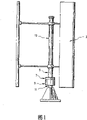
图1是根据本发明一个优选实施例包括模块化风力涡轮机-发电机组件的发电系统的正视图。Figure 1 is a front view of a power generation system including a modular wind turbine-generator assembly according to a preferred embodiment of the present invention.
图2是图1所示发电系统的俯视图。Fig. 2 is a top view of the power generation system shown in Fig. 1 .
图3是根据本发明一个优选实施例的发电系统的永磁体(P.M.)发电机的示意性横截视图。Fig. 3 is a schematic cross-sectional view of a permanent magnet (P.M.) generator of a power generation system according to a preferred embodiment of the present invention.
图4是根据本发明另一个优选实施例包括模块化风力涡轮机-发电机组件的发电系统的透视图。4 is a perspective view of a power generation system including a modular wind turbine-generator assembly according to another preferred embodiment of the present invention.
图5是根据本发明一个优选实施例的制动器组件的正视图。Figure 5 is a front view of a brake assembly according to a preferred embodiment of the present invention.
图6是图5所示制动器组件的侧视图。FIG. 6 is a side view of the brake assembly shown in FIG. 5 .
图7是图5和6所示制动器组件的电磁体子组件的正视图。7 is a front view of the electromagnet subassembly of the brake assembly shown in FIGS. 5 and 6 .
图8是图7所示电磁体子组件的侧视图。FIG. 8 is a side view of the electromagnet subassembly shown in FIG. 7 .
图9是图5和6所示制动器组件的制动器机构子组件的正视图。9 is a front view of the brake mechanism subassembly of the brake assembly shown in FIGS. 5 and 6 .
图10是图9所示制动器机构子组件的侧视图。FIG. 10 is a side view of the brake mechanism subassembly shown in FIG. 9 .
图11是根据本发明一个优选实施例的固定辐条的正视图。Figure 11 is a front view of a fixed spoke according to a preferred embodiment of the present invention.
图12是沿着图11中线A-A截取的横截视图。Fig. 12 is a cross-sectional view taken along line A-A in Fig. 11 .
图13是沿着图11中线B-B截取的横截视图。Fig. 13 is a cross-sectional view taken along line B-B in Fig. 11 .
图14是沿着图11中线C-C截取的横截视图。FIG. 14 is a cross-sectional view taken along line C-C in FIG. 11 .
具体实施方式Detailed ways
在下面的描述中,相同的参考数字涉及类似的元件。附图所示出和这里所描述的实施例、尺寸、物理性质和/或几何构造是优选的变化并且仅用于示例性的目的。In the following description, the same reference numerals refer to similar elements. The embodiments, dimensions, physical properties and/or geometries shown in the figures and described herein are preferred variations and are for illustrative purposes only.
在本描述的内容中,术语“发电系统”或“组件”包括所有类型的涡轮机-发电机组件等等。尽管本发明主要设计用于风力,但是其也能用于其它种类的驱动力和/或流体,比如举例来说水,或者用任何其它适合的项目,如同对于本领域技术人员而言很明显的。因此,术语“风”、“风流”或其任何其它相关的变化形式,不应当视为限制本发明的范围而是应当包括可使用本发明和本发明可适用的所有其它种类组件或项目。In the context of this description, the term "power generation system" or "assembly" includes all types of turbine-generator assemblies and the like. Although the invention is primarily designed for wind power, it can also be used with other kinds of driving forces and/or fluids, such as for example water, or with any other suitable items, as will be apparent to those skilled in the art . Accordingly, the terms "wind", "wind flow" or any other related variations thereof, should not be construed as limiting the scope of the present invention but should include all other kinds of components or items to which the present invention may be used and to which the present invention is applicable.
而且,在本描述的内容中,术语“系统”、“组件”和“设备”、“电力”和“动力”、“动力”和“能量”、“风”和“流体”、“辐条”和“臂”以及任何其它等同术语和/或其组合词语,可互换地使用。这也适用于这里所提及的任何其它相互等同的表达,如同对于本领域技术人员而言很明显的。Also, in the context of this description, the terms "system", "component" and "device", "electricity" and "power", "power" and "energy", "wind" and "fluid", "spoke" and "Arm" and any other equivalent terms and/or combinations thereof may be used interchangeably. This also applies to any other mutual equivalent expressions mentioned here, as would be obvious to a person skilled in the art.
另外,尽管如附图所示的本发明的优选实施例包括比如下面列出的各种部件等,以及尽管如所示的本发明的发电系统和相应部分的优选实施例由如这里所解释和示出的某些几何构造所构成,但是并非所有这些部件和几何形状对于本发明来说都是必要的并且因而不应当视为是限制性的,即不应当视为限制本发明的范围。应当理解到,如同对于本领域技术人员而言很明显的,其它适合的部件和其间的配合,以及其它适合的几何构造也可用于根据本发明的发电系统,如同这里将要简单解释的并且能从这里容易地得出,而不脱离本发明的范围。In addition, although the preferred embodiments of the present invention as shown in the drawings include various components, etc., such as listed below, and although the preferred embodiments of the power generation system and corresponding parts of the present invention as shown are composed of as explained herein and Certain geometries are shown, but not all of these components and geometries are essential to the invention and thus should not be considered limiting, ie, limiting the scope of the invention. It should be understood that, as will be apparent to those skilled in the art, other suitable components and cooperation therebetween, and other suitable geometrical configurations may also be used in the power generation system according to the present invention, as will be briefly explained herein and can be derived from It can be easily derived here without departing from the scope of the present invention.
泛泛地描述,如同附图中示例的,根据本发明的发电系统优选地包括能用于发电的模块化风力涡轮机-发电机组件,网格连接的或自主的,例如用于城市或遥远位置。Broadly described, as exemplified in the figures, the power generation system according to the invention preferably comprises a modular wind turbine-generator assembly that can be used to generate electricity, grid-connected or autonomous, for example for urban or remote locations.
根据本发明,风力系统族能以一种能用于各种平均风速位置的模块化方式并且通过选择能产生最大预测电能的适合模块来进行建造。According to the invention, a family of wind power systems can be built in a modular manner that can be used for various mean wind speed locations and by selecting suitable modules that produce the maximum predicted electrical energy.
所建议的发明避免了与现有技术相关的数个缺点,如同前面所讨论的。实际上,根据本发明的模块化方法提供了选择适合部分的优点,根据系统放置的风速条件使涡轮机-发电机系统处于额定工作范围。The proposed invention avoids several disadvantages associated with the prior art, as discussed above. In fact, the modular approach according to the invention offers the advantage of selecting suitable parts, according to the wind speed conditions where the system is placed, within the rated operating range of the turbine-generator system.
优选地,风力涡轮机使用空气动力轮廓的叶片,通过使用特殊轮廓的“辐条”将叶片连接至主轴,这在图1-4中较好地示出,并且更具体地在图11-14中示出。如同本领域技术人员基于下面的解释和附图所容易理解到的,不同长度的辐条改变涡轮机的直径并且隐含地允许涡轮机-发电机以最有效的工作面积起作用。Preferably, the wind turbine uses aerodynamically profiled blades connected to the main shaft through the use of specially profiled "spokes", which are best shown in Figures 1-4, and more particularly in Figures 11-14 out. As those skilled in the art will readily understand based on the following explanations and figures, the different lengths of the spokes change the diameter of the turbine and implicitly allow the turbine-generator to function with the most efficient working area.
还优选地,发电机(无论是感应的还是永磁体的)直接连接至涡轮机轴并且具有非标准的构造。在具有内部定子和外部转子时,发电机具有不运动的电触点,还使得永磁体易于安装(例如在永磁体发电机的情况下)以及在感应发电机的情况下对于外部“鼠笼绕组”的回转构造。在两种情况下,发电机的内部定子是相同的并且仅外部转子将根据所选择发电机的类型而不同。It is also preferred that the generator (whether induction or permanent magnet) is directly connected to the turbine shaft and is of non-standard construction. With an internal stator and an external rotor, the generator has non-moving electrical contacts, also allowing easy installation of permanent magnets (such as in the case of permanent magnet generators) and for external "squirrel cage windings in the case of induction generators "The rotary structure. In both cases the inner stator of the generator is the same and only the outer rotor will differ depending on the type of generator chosen.
上述优选的发电机构造通过选择不同功率电子学和控制方法提供了优化系统总体成本的可能性。The preferred generator configuration described above offers the possibility to optimize the overall system cost by selecting different power electronics and control methods.
例如,低成本的系统能用于加热或泵送应用(具有永磁体发电机),对于更高级的应用(网格连接的或者自主的网格发电机),这两种类型的发电机都能使用。For example, low-cost systems can be used for heating or pumping applications (with permanent magnet generators), and for more advanced applications (grid-connected or autonomous grid generators), both types of generators can use.
两个更加创新的元件优选地可加入涡轮机-发电机组件,也就是,优选地机械地连接在涡轮机和发电机之间的离合器;和优选地装配在发电机内的受控机电制动器。然而,应当注意到,离合器尽管是有利的,但对于根据本发明的发电系统的正确操作来说并不是绝对必要的,如同这里简短地解释那样,并且本领域技术人员也能从下面的描述中更好地理解到。Two more innovative elements may preferably be added to the turbine-generator assembly, namely, a clutch, preferably mechanically connected between the turbine and generator; and a controlled electromechanical brake, preferably fitted within the generator. It should be noted, however, that a clutch, although advantageous, is not absolutely necessary for the correct operation of the power generation system according to the invention, as briefly explained here and as those skilled in the art will appreciate from the following description understand better.
系统描述System specification
实际上,如同图1和2更好地示出,所建议和优选的风力涡轮机-发电机结构是具有原始元件的竖直轴线型。其优选地采用“Darrieus-H”型风力涡轮机3来将呈机械能形式的风能转变为经由顺轴5和离合器连接器7传输至外部发电机转子9。机械能经由与机械地安装至发电机轴11的内部发电机定子联接的磁性联接器转变为电能。轴支撑内部制动器并与风力涡轮机13的主轴对齐。In fact, as better shown in Figures 1 and 2, the proposed and preferred wind turbine-generator structure is of the vertical axis type with original elements. It preferably employs a "Darrieus-H" type wind turbine 3 to convert wind energy in the form of mechanical energy to be transmitted via a
风力系统(对于中等平均风速范围,大约4-7m/s)的设计遵循“Wind Turbines,Part 2,Design requirements for small wind turbines,#61400-2/CDV/IEC(E)standard of the International ElectrotechnicalCommission(风力涡轮机,第二部分,小型风力涡轮机的设计要求,国际机电委员会#61400-2/CDV/IEC(E)标准)”。根据这个标准,所建议的风力涡轮机是Class 4(SWT Class IV)的一部分并且在大约4m/s至6m/s的平均风速范围下具有最好的效率。The wind system (approximately 4-7m/s for the medium average wind speed range) is designed following "Wind Turbines, Part 2, Design requirements for small wind turbines, #61400-2/CDV/IEC(E) standard of the International Electrotechnical Commission( Wind Turbines, Part II, Design Requirements for Small Wind Turbines, International Electromechanical Commission #61400-2/CDV/IEC(E) Standard)". According to this standard, the proposed wind turbines are part of Class 4 (SWT Class IV) and have the best efficiency in the average wind speed range of about 4m/s to 6m/s.
优选地,涡轮机-发电机系统能装备有三个变化之一:Preferably, the turbine-generator system can be equipped with one of three variations:
-平均风速:4;5;6m/s;- Average wind speed: 4; 5; 6m/s;
-涡轮机直径:2.5;2;1.5m;- Turbine diameter: 2.5; 2; 1.5m;
-最大额定转速:250;310;410RPM;- Maximum rated speed: 250; 310; 410RPM;
-端速比:2-3;- End speed ratio: 2-3;
-涡轮机高度:3m;- Turbine height: 3m;
-叶片数目:3;- number of blades: 3;
-叶片空气动力翼面:具有四位序列的对称NACA,并且具有修改的尾缘以改善可制造性;-Blade aerodynamic airfoil: Symmetrical NACA with four-bit sequence and has a modified trailing edge to improve manufacturability;
-翼弦长度:0.4m;- Chord length: 0.4m;
-坚实性(solidity):0.8;0.6;0.48;- solidity: 0.8; 0.6; 0.48;
-2.5kW PM发电机;和-2.5kW PM generator; and
-估计年发电量:2000;2600;2900[kWh/年]。- Estimated annual power generation: 2000; 2600; 2900 [kWh/year].
还优选地,能采取特殊措施来改善涡轮机的性能:Also preferably, special measures can be taken to improve the performance of the turbine:
-端板安装至每个叶片以改善“纵横比”效应;- End plates fitted to each blade to improve the "aspect ratio" effect;
-“V”型轮廓的辐条以改善启动扭矩;- Spokes with "V" profile to improve starting torque;
-叶片的微振动用于“除冰”效应;和- micro-vibrations of the blades for a "de-icing" effect; and
-嵌在叶片中的不锈钢金属结构,具有双重作用:支撑结构和避雷防护(涡轮机还提供为安装避雷针)。- A stainless steel metal structure embedded in the blades with a double role: supporting structure and lightning protection (the turbine is also supplied for installation of lightning rods).
还优选地,三个叶片安装至主涡轮机轴,并且根据每个上述涡轮机具有不同长度的六个辐条。It is also preferred that three blades are mounted to the main turbine shaft and have six spokes of varying lengths for each of the above mentioned turbines.
还优选地,安装在涡轮机和发电机之间的自动离合器允许涡轮机在低风速下自由旋转并且在所产生的转矩高于发电机齿槽效应转矩的转速下让开(kick in)。Also preferably, an automatic clutch mounted between the turbine and generator allows the turbine to spin freely at low wind speeds and kick in at speeds where the torque produced is higher than the cogging torque of the generator.
为了易于安装,涡轮机-发电机组件的主轴优选地由两个部件组成,根据安装过程将安装在一起的涡轮机轴和发电机轴。涡轮机转子和发电机转子优选地经由适合的轴承安装至它们相应的轴。For ease of installation, the main shaft of the turbine-generator assembly preferably consists of two parts, the turbine shaft and the generator shaft to be fitted together according to the installation process. The turbine and generator rotors are preferably mounted to their respective shafts via suitable bearings.
还优选地,紧急制动器安装在发电机内作为对于超速、未料到的质量不平衡等的保护,这对本领域技术人员而言很明显。It is also preferred that an emergency brake is installed within the generator as protection against overspeed, unexpected mass imbalance etc., as will be apparent to those skilled in the art.
根据本发明的另一实施例并且如图3中更好地示出,用于系统中的第一种可能的发电机是具有竖直轴线的永磁体型。外部转子增大了系统的可靠性,因为永磁极(稀土磁体)胶粘在作为发电机部分磁路的旋转柱体的内部上。离心力有助于将磁体保持在原位。发电机的内部定子直接连接至固定的发电机轴并且具有特殊的构造。用于绕组的倾斜槽具有将发电机齿槽效应转矩降低至发电机额定转矩大约3%以下。这种定子类型将用于感应发电机的情况下。According to another embodiment of the invention and better shown in FIG. 3 , a first possible generator used in the system is of the permanent magnet type with a vertical axis. The external rotor increases the reliability of the system because the permanent poles (rare earth magnets) are glued to the inside of the rotating cylinder which is part of the magnetic circuit of the generator. Centrifugal force helps keep the magnets in place. The inner stator of the generator is directly connected to the fixed generator shaft and has a special construction. The inclined slots for the windings have the effect of reducing the generator cogging torque to about 3% below the generator rated torque. This stator type will be used in the case of induction generators.
还优选地,一体的机电制动器还是发电机构造的一部分。这个原始制动器经由脉冲电流进行控制并且具有“机械记忆”。不管闭合还是打开,制动器在正常操作期间将不会消耗任何能量,如同本领域技术人员容易理解到的那样。Also preferably, the integral electromechanical brake is also part of the generator construction. This primitive brake is controlled via pulsed current and has a "mechanical memory". Whether closed or open, the brake will not dissipate any energy during normal operation, as will be readily understood by those skilled in the art.
下面(表1)是所使用的永磁极发电机的第一个可能实施例的主要参数:Below (table 1) are the main parameters of the first possible embodiment of the permanent magnet pole generator used:
表1永磁体发电机的参数Table 1 Parameters of permanent magnet generator
实验结果显示了改善机会为:减少气隙、槽倾斜度、相阻、机器长度以及更好的效率。Experimental results showed improvement opportunities for: reduced air gap, slot inclination, phase resistance, machine length and better efficiency.
模块化概念描述:Modular concept description:
根据本发明的模块化概念的主要目标是提供一种可低成本构造的风力系统,其能容易地基于平均风速和涡轮机布置的竖直高度来改装以传送最大化的效率。The main objective of the modular concept according to the invention is to provide a low cost constructible wind power system which can be easily retrofitted to deliver maximum efficiency based on the average wind speed and the vertical height of the turbine arrangement.
主系统优选地包括下面的模块,包括下面的优选部件:The main system preferably includes the following modules, including the following preferred components:
a)涡轮机叶片,优选地其中三个由玻璃纤维增强的聚酯制成并且制造为使得表面粗糙度将带来最好的空气动力平滑性。端板改善叶片的纵横比效应。安装在涡轮机组件以及避雷防护装置中的叶片基于不锈钢叶片嵌件制成;a) Turbine blades, preferably three of which are made of glass fiber reinforced polyester and manufactured such that the surface roughness will give the best aerodynamic smoothness. The end plates improve the aspect ratio effect of the blade. Blades installed in turbine components as well as in lightning protection are based on stainless steel blade inserts;
b)涡轮机和发电机支撑结构—包括:b) Turbine and Generator Support Structure - including:
i)由两个零件制成的涡轮机和发电机轴,一个为涡轮机组件的一部分而第二个为发电机组件的一部分—这两个零件在最终装配工艺期间刚性地安装在一起作为轴组件;和i) turbine and generator shafts made of two parts, one part of the turbine assembly and the second part of the generator assembly—these two parts are rigidly mounted together as shaft assemblies during the final assembly process; and
ii)由两个零件制成的涡轮机和发电机转子,一个为涡轮机组件的一部分而第二个为发电机组件的一部分—这两个零件在最终装配工艺期间安装在一起作为转子组件—另外,在最终装配工艺期间轴和转子经由两个特殊的轴承安装在一起;ii) Turbine and generator rotors made from two parts, one part of the turbine assembly and the second part of the generator assembly—these two parts are assembled together during the final assembly process as the rotor assembly—in addition, Shaft and rotor are mounted together via two special bearings during the final assembly process;
c)离合器组件—将涡轮机和发电机转子连接起来。其作用是给发电机提供更好的启动转矩;c) Clutch assembly - connects the turbine to the generator rotor. Its function is to provide better starting torque for the generator;
d)电制动器—安装在发电机轴的下侧中—其作用是用于超速保护并且也能用于涡轮机速度控制;d) Electric brake - installed in the underside of the generator shaft - its role is for overspeed protection and can also be used for turbine speed control;
e)发电机—也构建为模块化概念并且具有定子设计以使得其能容纳感应式和永磁体转子类型;e) Generators - also built as a modular concept and having a stator design so that it can accommodate both induction and permanent magnet rotor types;
f)辐条,优选地其中六个—将叶片与涡轮机转子组件相连接—辐条的“V”形形状形成了空气动力学上的不对称,这对于涡轮机启动转矩有着正面的贡献—各种辐条长度将有助于不同的涡轮机扫掠面积;和f) Spokes, preferably six of them - Connecting the blades to the turbine rotor assembly - The "V" shape of the spokes creates an aerodynamic asymmetry which positively contributes to the turbine starting torque - Various spokes The length will facilitate different turbine swept areas; and
g)可选的制动模块能用作叶片和辐条之间的连接。其作用是改变叶片的安装角度并形成涡轮机的空气动力制动器。g) An optional braking module can be used as a connection between blades and spokes. Its function is to change the installation angle of the blades and form an aerodynamic brake of the turbine.
下面(表2)是能用于三种不同平均风速位置的三种不同涡轮机参数的示例。仅有的修改是辐条的长度。模块的其余部分则相同。装机功率:约2500W。Below (Table 2) is an example of three different turbine parameters that can be used for three different mean wind speed locations. The only modification is the length of the spokes. The rest of the module is the same. Installed power: about 2500W.
表2涡轮机参数Table 2 Turbine parameters
只要涡轮机圆周速度小于约32.5m/s,任何其它组合都是可能的,如同本领域技术人员易于理解到的。Any other combination is possible as long as the peripheral turbine speed is less than about 32.5 m/s, as will be readily appreciated by those skilled in the art.
具有带控制电磁体的优选磁制动器和预压缩盘式制动器的制动器Brakes with preferred magnetic brakes and pre-compression disc brakes with control electromagnets 组件components
根据本发明的制动器组件,在这里还称为“永磁体制动器”,避免了前面讨论的现有技术的缺点,其原因在于可动的盘垫将仅在制动器动作期间压靠旋转设备并且因而这将避免弹性摩擦。还优选地,螺旋弹簧将两个制动垫(DB1,DB2)与可动的盘式制动器压到一起。还优选地,只要永磁体没有被磁化,制动器将一直处于“on”(打开)状态。通过将电流脉冲施加于控制电磁体,永磁体将被磁化并且制动器将变为“off”(关闭)。还优选地,只要需要,永磁体将维持制动器处于“off”配置。为了将制动器打开,将第二电流脉冲施加于控制电磁体并将永磁体去磁,并且因而盘式制动器垫将再次受压。此制动动作期间的能量消耗将接近零,因为仅需要的能量是产生用于磁化和去磁永磁体的电流脉冲。The brake assembly according to the invention, also referred to herein as a "permanent magnet brake", avoids the disadvantages of the prior art discussed above in that the movable disc pad will only press against the rotating equipment during brake action and thus this Elastic friction will be avoided. Also preferably, a helical spring presses the two brake pads (DB1, DB2) together with the movable disc brake. Also preferably, the brake will remain "on" as long as the permanent magnet is not magnetized. By applying a current pulse to the control electromagnet, the permanent magnet will be magnetized and the brake will be turned "off". Also preferably, the permanent magnet will maintain the brake in the "off" configuration as long as required. To open the brake, a second current pulse is applied to the control electromagnet and demagnetizes the permanent magnet, and thus the disc brake pad will be compressed again. The energy consumption during this braking action will be close to zero, since the only energy required is to generate the current pulses used to magnetize and demagnetize the permanent magnets.
制动器组件优选地包括制动器子组件“A”和电磁体子组件“B”。制动器子组件“A”优选地包括下面的部件:铁磁性电枢15;摩擦盘DB1(例如金属支架和盘垫)17;具有用于与旋转设备相结合的槽“a”的可动摩擦盘19;摩擦盘DB2(例如支架和盘垫)21;弹簧垫圈23;用于产生压缩力的螺旋弹簧25;和相应的螺钉27。The brake assembly preferably includes a brake subassembly "A" and an electromagnet subassembly "B". The brake subassembly "A" preferably comprises the following components:
电磁体子组件“B”优选地包括下面的部件:金属包围件29;电磁体线圈31;永磁体33;用于与旋转设备相连接的槽“b”;和用于螺旋弹簧35的槽“c”。The electromagnet subassembly "B" preferably includes the following components:
上述“永磁体制动器”所产生的优点的示例如下:低的制动器能量消耗;低动力的电磁体子组件(例如所需电磁力较低);和弹性摩擦的避免或显著降低。Examples of the advantages resulting from the "permanent magnet brake" described above are: low brake energy consumption; low powered electromagnet subassembly (eg lower required electromagnetic force); and avoidance or significant reduction of elastic friction.
优选地,永磁体制动器(具有预压缩的盘式制动器)使用固定的盘式制动器DB1、DB2 17;可动的盘式制动器19和由弹簧垫圈23和螺旋弹簧25所预压缩的盘垫21,其中压力调节用相应的螺钉27来实现并且其中制动器动作由制动器子组件“A”的轴向位移以及可动盘摩擦盘19与待制动旋转设备的机械结合来实现。Preferably, permanent magnet brakes (disc brakes with precompression) use fixed disc brakes DB1,
还优选地,将制动器维持在释放状态的力通过使用由施加于电磁线圈31的电流脉冲所磁化的永磁体由电磁子组件“B”来实现。Also preferably, the force to maintain the brake in the released state is achieved by the electromagnetic subassembly "B" using permanent magnets magnetized by current pulses applied to the
还优选地,将制动器维持在啮合状态的力由预压缩的制动器盘和通过使用由施加于电磁线圈31的电流脉冲所去磁化的永磁体由电磁子组件“B”来实现。Also preferably, the force to maintain the brakes in engagement is achieved by the pre-compressed brake disc and by the electromagnetic subassembly "B" by using permanent magnets demagnetized by current pulses applied to the
还优选地,永磁体制动器(具有预压缩的盘式制动器)用作机电触发器,其中从制动器啮合到制动器释放(和反之)的状态变化通过控制电磁设备去磁和磁化永磁体来实现。Also preferably, a permanent magnet brake (disc brake with pre-compression) is used as the electromechanical trigger, where the change of state from brake engaged to brake released (and vice versa) is achieved by controlling an electromagnetic device to demagnetize and magnetize the permanent magnet.
还优选地,永磁体制动器(具有预压缩的盘式制动器)对于高效率的发电系统(包括风能发电)而言使用最小化的能量消耗。It is also preferred that permanent magnet brakes (disc brakes with pre-compression) use minimized energy consumption for high efficiency power generation systems, including wind power generation.
用于竖直轴线风力涡轮机的支撑臂:Support arms for vertical axis wind turbines:
常规“固定辐条”(这里也称为“支撑臂”)的作用是将叶片连接至风力涡轮机的竖直轴。臂的形状、重量和尺寸是重要的参数并且通常对于涡轮机的总体性能有着负面的影响。它们通常导致空气动力学上的损失并且降低系统的效率。The function of conventional "fixed spokes" (also referred to herein as "support arms") is to connect the blade to the vertical shaft of the wind turbine. The shape, weight and size of the arms are important parameters and generally have a negative impact on the overall performance of the turbine. They generally lead to aerodynamic losses and reduce the efficiency of the system.
已知具有竖直叶片的H-Darrieus型风力涡轮机是端速比大于整体(叶片的转速高于风速)的基部提升涡轮机(lift-base turbine)。还已知这种涡轮机类型通常不会由于可能的理论上的负启动转矩而自己启动(根据朝向风的叶片位置、轴承中的摩擦损失和发电机的齿槽效应转矩)。而且,支撑臂通常将引入制动分量,这将形成额外的阻力和较低的涡轮机效率。H-Darrieus type wind turbines with vertical blades are known to be lift-base turbines with a greater tip speed ratio than the bulk (blades rotate at a higher speed than the wind speed). It is also known that this type of turbine generally does not start itself due to a possible theoretical negative starting torque (according to blade position towards the wind, frictional losses in bearings and cogging torque of the generator). Also, the support arms will generally introduce a braking component which will create additional drag and lower turbine efficiency.
根据本发明的固定辐条或“支撑臂”避免了以上缺点,因为每个支撑臂优选地设有两个主要部件:a)空气动力轮廓,优选地接近叶片;和b)“V”形截面轮廓,优选地接近竖直轴。Fixed spokes or "support arms" according to the invention avoid the above disadvantages, since each support arm is preferably provided with two main components: a) an aerodynamic profile, preferably close to the blade; and b) a "V" cross-sectional profile , preferably close to the vertical axis.
“V”形截面部分的优化长度取决于涡轮机的计算端速比。已知V形截面是基于制动的轮廓并且转速不能高于风速。根据本发明,这个部分的长度优选地计算为使得在涡轮机的额定风速范围内其端速小于或等于整体(unity)。The optimal length of the "V" shaped section depends on the calculated end speed ratio of the turbine. It is known that the V-section is based on the braking profile and cannot rotate faster than the wind speed. According to the invention, the length of this section is preferably calculated such that its tip speed is less than or equal to unity within the rated wind speed range of the turbine.
根据本发明的这种支撑臂或固定辐条的优点的示例如下:空气动力轮廓的部分将降低总体系统损失;由于建筑物屋顶顶部上已有的湍流,这个部分还能增大涡轮机的启动转矩;并且“V”形截面部分将在产生涡轮机的正启动转矩中具有主要作用(在涡轮机额定速度范围的上限之上,这个部分将在产生阻力转矩中具有有效的作用,因此在高风速时保护涡轮机)。An example of the advantages of such a support arm or fixed spoke according to the invention is as follows: the part of the aerodynamic profile will reduce the overall system losses; this part can also increase the starting torque of the turbine due to the existing turbulent flow on top of the roof of the building ; and the "V" section section will have a major role in generating the positive starting torque of the turbine (above the upper limit of the rated speed range of the turbine, this section will have an effective role in generating drag torque, so at high wind speeds to protect the turbine).
根据本发明这个优选实施例的固定辐条或“支撑臂”是用于H-Darrieus竖直轴线风力涡轮机的支撑臂,其包括用于产生涡轮机启动转矩的“V”形截面部分(优选地接近竖直的涡轮机轴)和在正常操作期间降低阻力转矩的空气动力部分(优选地接近叶片)。The stationary spokes or "support arms" according to this preferred embodiment of the invention are support arms for H-Darrieus vertical axis wind turbines which include a "V" section section (preferably close to vertical turbine shaft) and an aerodynamic section (preferably close to the blades) that reduces drag torque during normal operation.
涡轮机-发电机组件和相应的部分优选地由基本上刚性的材料制成,比如金属材料(钢等)、硬化聚合物、复合材料等,以便根据组件计划的具体应用和所考虑的不同参数(风力等)确保其正确的操作,如同对于本领域技术人员而言很明显的。The turbine-generator assembly and corresponding parts are preferably made of substantially rigid materials, such as metallic materials (steel, etc.), hardened polymers, composite materials, etc., in order to depend on the specific application for which the assembly is planned and the different parameters considered ( wind, etc.) to ensure its correct operation, as would be apparent to a person skilled in the art.
如同现在将更好地理解到的,本发明是对于现有技术的显著改进,因为,模块化的涡轮机-发电机组件可用于低竖直轴线风力系统的族,并且可适用于特定位置的不同平均风速,该系统设计为用于具有期望输出动力的中等平均风速,统一的解决方案包括一体的涡轮机-发电机-制动器-离合器并使用用于自启动操作的“V”形轮廓辐条。As will now be better understood, the present invention is a significant improvement over the prior art in that the modular turbine-generator assembly can be used in a family of low vertical axis wind power systems and can be adapted to different locations in a particular location. Average wind speeds, the system is designed for moderate average wind speeds with desired output power, the unified solution includes an integrated turbine-generator-brake-clutch and uses "V" profiled spokes for self-starting operation.
本发明还是特别有利地,因为其由模块化的涡轮机-发电机组件组成,其中涡轮机通过使用可变长度的辐条连接至主轴以调节选定位置的平均风速。The invention is also particularly advantageous because it consists of a modular turbine-generator assembly where the turbine is connected to the main shaft through the use of variable length spokes to adjust the average wind speed at selected locations.
本发明还是特别有利地,因为:涡轮机经由自动离心式离合器连接至发电机;竖直轴线发电机具有带有内部定子和外部转子的特殊构造;涡轮机具有作为端板的创新性元件以改善叶片的“纵横比”效应以及固定辐条不对称的空气动力轮廓(V形轮廓)以增大涡轮机的启动转矩;其具有发电机定子的特殊构造(倾斜槽)以降低发电机的齿槽效应转矩;其具有将用于永磁体发电机或感应发电机中的独特的定子设计;以及其特征在于可调节的离心式离合器以超过发电机的阻力启动转矩。The invention is also particularly advantageous because: the turbine is connected to the generator via an automatic centrifugal clutch; the vertical axis generator has a special construction with an inner stator and an outer rotor; the turbine has an innovative element as an end plate to improve the The "aspect ratio" effect and the asymmetrical aerodynamic profile of the fixed spokes (V-shaped profile) to increase the starting torque of the turbine; it has a special configuration of the generator stator (inclined slots) to reduce the cogging torque of the generator ; it has a unique stator design to be used in a permanent magnet generator or an induction generator; and it features an adjustable centrifugal clutch to exceed the resistive starting torque of the generator.
本发明也是对于现有技术已知设备的改进并且显示了若干优点,因为,如同很多现在从以上描述中更好地理解到的,这是相比现有技术可用的那些而言更加可靠、更易于使用、更易于维护、更安全、更有效且更加节省成本的涡轮机-发电机组件。The present invention is also an improvement over the known devices of the prior art and exhibits several advantages because, as many are now better understood from the above description, this is more reliable, more efficient than those available in the prior art. Turbine-generator assemblies that are easier to use, easier to maintain, safer, more efficient and more cost-effective.
当然,在不脱离本发明如所附权利要求所限定的范围之下能对上述实施例做出很多变型。There are, of course, many variations that can be made to the embodiments described above without departing from the scope of the invention as defined in the appended claims.
Claims (24)
Applications Claiming Priority (2)
| Application Number | Priority Date | Filing Date | Title |
|---|---|---|---|
| US70301305P | 2005-07-28 | 2005-07-28 | |
| US60/703,013 | 2005-07-28 |
Publications (1)
| Publication Number | Publication Date |
|---|---|
| CN101233316A true CN101233316A (en) | 2008-07-30 |
Family
ID=37682967
Family Applications (1)
| Application Number | Title | Priority Date | Filing Date |
|---|---|---|---|
| CNA2006800277215A Pending CN101233316A (en) | 2005-07-28 | 2006-07-28 | Modular Wind Turbine-Generator Assemblies |
Country Status (5)
| Country | Link |
|---|---|
| US (1) | US8013464B2 (en) |
| EP (1) | EP1907693A1 (en) |
| CN (1) | CN101233316A (en) |
| CA (1) | CA2614929A1 (en) |
| WO (1) | WO2007012195A1 (en) |
Cited By (8)
| Publication number | Priority date | Publication date | Assignee | Title |
|---|---|---|---|---|
| CN102146887A (en) * | 2010-02-08 | 2011-08-10 | 国能风力发电有限公司 | High-efficiency and large-power vertical axis wind power generator |
| CN102465839A (en) * | 2010-11-05 | 2012-05-23 | 胡广生 | Wind power generation system arranged in three-dimensional matrix and construction method for wind power generation system |
| CN101839212B (en) * | 2009-03-17 | 2012-05-23 | 欧振玉 | Vertical axis wind power generating device |
| CN102733866A (en) * | 2012-07-09 | 2012-10-17 | 中国科学院工程热物理研究所 | Compact high-load power turbine generator |
| CN102859187A (en) * | 2010-03-23 | 2013-01-02 | 维斯塔斯风力系统集团公司 | A method for de-icing the blades of a wind turbine and a wind turbine with a de-icing system |
| CN103912457A (en) * | 2014-04-15 | 2014-07-09 | 新疆奥奇新能源科技有限公司 | Automatic verticality structure applicable to vertical-axis wind turbine |
| KR101565466B1 (en) | 2014-08-06 | 2015-11-04 | 주식회사 웨스텍 | High-efficiency vertical axis wind power apparatus operating for low speed wind conditions |
| CN105508139A (en) * | 2016-01-20 | 2016-04-20 | 雒龙泉 | Combined vertical axis wind driven generator device |
Families Citing this family (39)
| Publication number | Priority date | Publication date | Assignee | Title |
|---|---|---|---|---|
| JPWO2006095396A1 (en) * | 2005-03-07 | 2008-08-14 | 株式会社アイ・ピー・ビー | Vertical axis wind turbine blade and lift type vertical axis wind turbine equipped with the blade |
| US7633176B1 (en) * | 2005-08-17 | 2009-12-15 | Earth Turbines, Inc. | Direct drive induction electrical power generator |
| EP2299112B1 (en) * | 2007-03-23 | 2015-05-13 | Vestas Wind Systems A/S | Method for establishing a wind turbine generator with one or more permanent magnet (pm) rotors, wind turbine nacelle and wind turbine |
| CN101821500A (en) * | 2007-10-05 | 2010-09-01 | 维斯塔斯风力系统有限公司 | Method for de-icing a blade of a wind turbine, wind turbine and use thereof |
| CN101451499B (en) * | 2007-11-28 | 2012-02-08 | 蔡心一 | Constant directional four-quadrant full lift force vertical axis wind motor |
| NL1035727C2 (en) * | 2008-07-21 | 2010-01-22 | Ecofys Invest B V | Device for utilizing wave energy and method thereof. |
| US20100024311A1 (en) * | 2008-07-30 | 2010-02-04 | Dustin Jon Wambeke | Wind turbine assembly with tower mount |
| WO2010091374A2 (en) * | 2009-02-06 | 2010-08-12 | Richard Nils Young | Vertical-axis wind turbine |
| US8030792B2 (en) | 2009-03-12 | 2011-10-04 | Eastern Wind Power | Vertical axis wind turbine system |
| US8648483B2 (en) | 2009-03-12 | 2014-02-11 | Eastern Wind Power | Vertical axis wind turbine system |
| ITMI20090403A1 (en) * | 2009-03-17 | 2010-09-18 | Linz Electric S R L | ROTARY MOTION METHOD OF A SOUNDPROOF WIND TURBINE. |
| US8378518B2 (en) * | 2009-03-26 | 2013-02-19 | Terra Telesis, Inc. | Wind power generator system, apparatus, and methods |
| US8536720B2 (en) | 2009-04-23 | 2013-09-17 | Windstream Technologies, Inc. | Modular wind energy unit with simple electrical connections |
| WO2010131968A2 (en) * | 2009-05-13 | 2010-11-18 | Hydroring Capital B.V. | Bearing for energy converter for flowing fluids and gases |
| SE535025C2 (en) * | 2009-06-08 | 2012-03-20 | Ge Wind Energy Norway As | Wind turbines and a method for operating a wind turbine |
| CN201418000Y (en) * | 2009-06-26 | 2010-03-03 | 北京希翼新兴能源科技有限公司 | Outer rotor generator for vertical shaft wind power generator |
| CN201865840U (en) | 2009-09-18 | 2011-06-15 | 北京希翼新兴能源科技有限公司 | Impeller and windwheel of vertical shaft wind power generator |
| US8080891B2 (en) * | 2009-09-25 | 2011-12-20 | General Electric Company | Hybrid braking system and method |
| US20110204638A1 (en) * | 2010-02-25 | 2011-08-25 | Stuart Lahtinen | Wind turbine with integrated rotor and generator assembly |
| US7988413B2 (en) | 2010-04-23 | 2011-08-02 | Eastern Wind Power | Vertical axis wind turbine |
| EP2381090A3 (en) * | 2010-04-25 | 2012-10-03 | Iiapia | Leverage-maximizing vertical axis waterwheel rotor |
| CN102312786A (en) * | 2010-06-30 | 2012-01-11 | 刘守熙 | Wind power generation device |
| TWI425145B (en) * | 2010-11-15 | 2014-02-01 | Hiwin Mikrosystem Corp | Vertical wind power generator with automatically retractable blades |
| US8536727B2 (en) * | 2011-02-03 | 2013-09-17 | Suey-Yueh Hu | Wind energy generating system |
| US9041240B2 (en) * | 2011-05-02 | 2015-05-26 | Tadashi Ishimine | Wind turbine apparatus |
| US9644611B2 (en) * | 2011-08-31 | 2017-05-09 | Thomas Jones | Vertical axis wind turbines |
| TW201331469A (en) * | 2012-01-19 | 2013-08-01 | Yan-Shan Lin | Vertical axis wind turbine |
| KR101157389B1 (en) * | 2012-02-03 | 2012-06-18 | 주식회사 한림메카트로닉스 | Wind power generation apparatus for low wind speed |
| GB2499219A (en) * | 2012-02-08 | 2013-08-14 | Nenuphar | Vertical axis wind turbine with roof generator |
| CH706294A1 (en) * | 2012-03-21 | 2013-09-30 | Pegasus Lizenz Ag | Method for manufacturing of vertical axis-wind turbine and its startup at operating location, involves selecting rotor from set of rotors under specific operating conditions and mounting turbine |
| TWI522529B (en) * | 2013-06-28 | 2016-02-21 | 國立臺灣海洋大學 | Vertical axis wind turbine |
| US20150086366A1 (en) * | 2013-09-24 | 2015-03-26 | Robert Jeffrey Barnes | Wind turbine blade and blade hub |
| US9647522B2 (en) | 2014-04-29 | 2017-05-09 | Ishwar Ram Singh | Linear induction generator using magnetic repulsion |
| US9853529B2 (en) | 2014-04-29 | 2017-12-26 | Ishwar Ram Singh | Linear induction generator using magnetic repulsion |
| GB2546635B (en) * | 2015-12-12 | 2019-09-04 | Spinetic Energy Ltd | Wind turbine apparatus with rotor to blade connection |
| DE102017109273A1 (en) * | 2017-04-28 | 2018-10-31 | Nmb Star Holding Gmbh | Werbewind conditioning |
| JP7040792B2 (en) * | 2019-10-15 | 2022-03-23 | 力也 阿部 | Lift type vertical axis feng shui wheel |
| GB2606390B (en) * | 2021-05-06 | 2023-06-07 | Achelous Energy Ltd | Systems and devices for a floating renewable power station |
| GB2608101B (en) * | 2021-05-28 | 2025-09-24 | Airde Pte Ltd | Improvements in wind turbines |
Family Cites Families (32)
| Publication number | Priority date | Publication date | Assignee | Title |
|---|---|---|---|---|
| GB2033019A (en) | 1978-11-02 | 1980-05-14 | Goodridge W | Wind turbine |
| US4299537A (en) * | 1979-06-19 | 1981-11-10 | Evans Frederick C | Interlinked variable-pitch blades for windmills and turbines |
| US4321005A (en) * | 1980-01-03 | 1982-03-23 | Black Jerimiah B | Modular windmill installation |
| US4430044A (en) * | 1981-11-23 | 1984-02-07 | Liljegren L Kenyon | Vertical axis wind turbine |
| US4415312A (en) * | 1982-03-11 | 1983-11-15 | Wixlin, Inc. | Transverse axis fluid turbine |
| FR2541383A1 (en) | 1982-03-16 | 1984-08-24 | Schweizer Otto | Wind-powered turbine which can be situated in different positions |
| US5183386A (en) * | 1988-12-23 | 1993-02-02 | Lewis Feldman | Vertical axis sail bladed wind turbine |
| US4979871A (en) * | 1989-11-17 | 1990-12-25 | Reiner Harold E | Wind turbine |
| US5252029A (en) | 1991-09-13 | 1993-10-12 | Barnes Robert J | Vertical axis wind turbine |
| GB9217698D0 (en) | 1992-08-20 | 1992-09-30 | Coker Clive M | Upright axis wind turbine |
| DE59409401D1 (en) * | 1993-09-30 | 2000-07-20 | Egon Gelhard Engineering | WIND TURBINE WITH H-ROTOR |
| DE29705410U1 (en) | 1997-03-25 | 1997-09-25 | Wilhelm, Alfred, 53840 Troisdorf | Combined wind / solar power machine |
| GB9721261D0 (en) | 1997-10-08 | 1997-12-10 | Store Roland | Adjustable wind turbine |
| US5997252A (en) * | 1997-12-24 | 1999-12-07 | Miller; Duane G. | Wind driven electrical power generating apparatus |
| EP0957265A3 (en) | 1998-05-11 | 2001-10-24 | Luigi Sanna | Vertical axis wind turbine |
| US6394745B1 (en) * | 2000-05-26 | 2002-05-28 | Saeed Quraeshi | Straight-bladed vertical axis wind turbine |
| AU2002222320A1 (en) | 2000-12-04 | 2002-06-18 | Arup (Pvt) Ltd | Fan assembly |
| US6784566B2 (en) | 2001-01-25 | 2004-08-31 | Robert Nason Thomas | Coupled vortex vertical axis wind turbine |
| US6857846B2 (en) | 2001-06-19 | 2005-02-22 | Lewis H. Miller | Stackable vertical axis windmill |
| US20040184909A1 (en) | 2001-06-19 | 2004-09-23 | Miller Lewis H. | Multi-rotor blade stackable vertical axis windmill |
| US6629815B2 (en) * | 2001-08-13 | 2003-10-07 | Dennis W. Lusk | Peripheral turbine support system |
| WO2003027498A1 (en) | 2001-08-30 | 2003-04-03 | Ricker Jonathan C | Multiaxis turbine |
| EA003784B1 (en) | 2001-11-08 | 2003-08-28 | Альберт Васильевич Болотов | Wind energetic unit (weu) and wind power station (wps) |
| AU2003213017A1 (en) * | 2002-02-11 | 2003-09-04 | The Trustees Of Dartmouth College | Systems and methods for modifying an ice-to-object interface |
| US6849964B2 (en) | 2002-09-13 | 2005-02-01 | Axis Usa, Inc. | Wind powered energy generating machine |
| JP3451085B1 (en) * | 2002-09-20 | 2003-09-29 | 常夫 野口 | Windmill for wind power generation |
| US7246991B2 (en) * | 2002-09-23 | 2007-07-24 | John Vanden Bosche | Wind turbine blade deflection control system |
| US20040086373A1 (en) * | 2002-11-06 | 2004-05-06 | Page John S. | Leveredged wind turbine w/ multiple generators |
| GB2404700A (en) | 2003-08-01 | 2005-02-09 | Robin Matthew Hilder | Roof mounted wind turbine |
| US6890152B1 (en) * | 2003-10-03 | 2005-05-10 | General Electric Company | Deicing device for wind turbine blades |
| JPWO2005116446A1 (en) * | 2004-05-27 | 2008-04-03 | 株式会社アイ・ピー・ビー | Blades for vertical axis wind turbines and vertical axis wind turbines |
| US20060210389A1 (en) * | 2005-03-17 | 2006-09-21 | Andre St-Germain | Wind powered turbine |
-
2006
- 2006-07-28 WO PCT/CA2006/001255 patent/WO2007012195A1/en not_active Ceased
- 2006-07-28 EP EP06775054A patent/EP1907693A1/en not_active Withdrawn
- 2006-07-28 US US11/996,333 patent/US8013464B2/en not_active Expired - Fee Related
- 2006-07-28 CN CNA2006800277215A patent/CN101233316A/en active Pending
- 2006-07-28 CA CA002614929A patent/CA2614929A1/en not_active Abandoned
Cited By (14)
| Publication number | Priority date | Publication date | Assignee | Title |
|---|---|---|---|---|
| CN101839212B (en) * | 2009-03-17 | 2012-05-23 | 欧振玉 | Vertical axis wind power generating device |
| WO2011094916A1 (en) * | 2010-02-08 | 2011-08-11 | 国能风力发电有限公司 | High-efficiency high-power vertical axis wind generator |
| WO2011095054A1 (en) * | 2010-02-08 | 2011-08-11 | 国能风力发电有限公司 | High-efficiency high-power vertical axis wind generator |
| CN102146887A (en) * | 2010-02-08 | 2011-08-10 | 国能风力发电有限公司 | High-efficiency and large-power vertical axis wind power generator |
| CN102859187A (en) * | 2010-03-23 | 2013-01-02 | 维斯塔斯风力系统集团公司 | A method for de-icing the blades of a wind turbine and a wind turbine with a de-icing system |
| CN102859187B (en) * | 2010-03-23 | 2015-12-09 | 维斯塔斯风力系统集团公司 | For wind turbine blade deicing method and there is the wind turbine of deicing system |
| CN102465839A (en) * | 2010-11-05 | 2012-05-23 | 胡广生 | Wind power generation system arranged in three-dimensional matrix and construction method for wind power generation system |
| CN102465839B (en) * | 2010-11-05 | 2015-01-07 | 胡广生 | Wind power generation system arranged in three-dimensional matrix and construction method for wind power generation system |
| CN102733866B (en) * | 2012-07-09 | 2014-06-04 | 中国科学院工程热物理研究所 | Compact high-load power turbine generator |
| CN102733866A (en) * | 2012-07-09 | 2012-10-17 | 中国科学院工程热物理研究所 | Compact high-load power turbine generator |
| CN103912457A (en) * | 2014-04-15 | 2014-07-09 | 新疆奥奇新能源科技有限公司 | Automatic verticality structure applicable to vertical-axis wind turbine |
| CN103912457B (en) * | 2014-04-15 | 2016-09-21 | 新疆奥奇新能源科技有限公司 | It is adapted to the automatic vertical structure of vertical axis aerogenerator |
| KR101565466B1 (en) | 2014-08-06 | 2015-11-04 | 주식회사 웨스텍 | High-efficiency vertical axis wind power apparatus operating for low speed wind conditions |
| CN105508139A (en) * | 2016-01-20 | 2016-04-20 | 雒龙泉 | Combined vertical axis wind driven generator device |
Also Published As
| Publication number | Publication date |
|---|---|
| WO2007012195A1 (en) | 2007-02-01 |
| CA2614929A1 (en) | 2007-02-01 |
| EP1907693A1 (en) | 2008-04-09 |
| US20080309090A1 (en) | 2008-12-18 |
| US8013464B2 (en) | 2011-09-06 |
Similar Documents
| Publication | Publication Date | Title |
|---|---|---|
| CN101233316A (en) | Modular Wind Turbine-Generator Assemblies | |
| US20100111689A1 (en) | Ultimate wind turbine system method and apparatus | |
| EP2220759A1 (en) | Self-starting darrieus wind turbine | |
| JP2012527864A (en) | Vertical axis wind turbine and generator therefor | |
| JPH11299197A (en) | Wind power generator | |
| CN102926939A (en) | Five-degree-of-freedom full-suspension vertical shaft disc type wind driven generator | |
| WO2011071841A2 (en) | Wind-driven electric power generation system adapted for mounting along the side of vertical, man-made structures such as large buildings | |
| KR20140050568A (en) | Nd-fe-b permanent magnet without dysprosium, rotor assembly, electromechanical transducer, wind turbine | |
| CN106640693A (en) | Vertical type direct connection draught fan | |
| CN201515291U (en) | Direct-drive wind generator | |
| CN101841209B (en) | Direct-drive wind driven generator | |
| CN202017579U (en) | Double disk type wind driven generator | |
| Patel et al. | Design and performance analysis of a magnetically levitated vertical axis wind turbine based axial flux PM generator | |
| CN202937410U (en) | Five-degree-of-freedom full-suspension vertical shaft disc type wind driven generator | |
| CN101656444A (en) | Automatic speed-regulation permanent magnet wind-power generator with interior ventilation perpendicular shaft | |
| CN112302876A (en) | Bidirectional vertical shaft frame type wind generating set | |
| CN2826811Y (en) | Highly effective super-low speed wind-power generator | |
| RU109806U1 (en) | WIND GENERATOR (OPTIONS) | |
| WO2010118905A2 (en) | Apparatus for injecting current | |
| RU2245458C1 (en) | Wind-powered generator | |
| CN205977551U (en) | Wind -driven generator | |
| CN105790501B (en) | Permanent magnet generator with heater | |
| CN203925884U (en) | A kind of vertical axis aerogenerator | |
| CN202832984U (en) | Magnetic eddy current type heat storage device capable of transforming kinetic energy to heat energy | |
| CN209569120U (en) | Hybrid Magnetic Bearing Dual Wind Turbine Based on Radial Excitation and Permanent Magnet |
Legal Events
| Date | Code | Title | Description |
|---|---|---|---|
| C06 | Publication | ||
| PB01 | Publication | ||
| C10 | Entry into substantive examination | ||
| SE01 | Entry into force of request for substantive examination | ||
| C02 | Deemed withdrawal of patent application after publication (patent law 2001) | ||
| WD01 | Invention patent application deemed withdrawn after publication |
Open date: 20080730 |