CN101231709A - Structure of memory card and method thereof - Google Patents
Structure of memory card and method thereof Download PDFInfo
- Publication number
- CN101231709A CN101231709A CNA2008100007931A CN200810000793A CN101231709A CN 101231709 A CN101231709 A CN 101231709A CN A2008100007931 A CNA2008100007931 A CN A2008100007931A CN 200810000793 A CN200810000793 A CN 200810000793A CN 101231709 A CN101231709 A CN 101231709A
- Authority
- CN
- China
- Prior art keywords
- die
- dielectric layer
- layer
- redistribution
- redistribution layer
- Prior art date
- Legal status (The legal status is an assumption and is not a legal conclusion. Google has not performed a legal analysis and makes no representation as to the accuracy of the status listed.)
- Pending
Links
Images


Classifications
-
- G—PHYSICS
- G11—INFORMATION STORAGE
- G11C—STATIC STORES
- G11C5/00—Details of stores covered by group G11C11/00
- G11C5/02—Disposition of storage elements, e.g. in the form of a matrix array
-
- G—PHYSICS
- G11—INFORMATION STORAGE
- G11C—STATIC STORES
- G11C5/00—Details of stores covered by group G11C11/00
- G11C5/02—Disposition of storage elements, e.g. in the form of a matrix array
- G11C5/025—Geometric lay-out considerations of storage- and peripheral-blocks in a semiconductor storage device
-
- G—PHYSICS
- G11—INFORMATION STORAGE
- G11C—STATIC STORES
- G11C5/00—Details of stores covered by group G11C11/00
- G11C5/06—Arrangements for interconnecting storage elements electrically, e.g. by wiring
- G11C5/063—Voltage and signal distribution in integrated semi-conductor memory access lines, e.g. word-line, bit-line, cross-over resistance, propagation delay
-
- H—ELECTRICITY
- H10—SEMICONDUCTOR DEVICES; ELECTRIC SOLID-STATE DEVICES NOT OTHERWISE PROVIDED FOR
- H10W—GENERIC PACKAGES, INTERCONNECTIONS, CONNECTORS OR OTHER CONSTRUCTIONAL DETAILS OF DEVICES COVERED BY CLASS H10
- H10W70/00—Package substrates; Interposers; Redistribution layers [RDL]
- H10W70/60—Insulating or insulated package substrates; Interposers; Redistribution layers
-
- H—ELECTRICITY
- H10—SEMICONDUCTOR DEVICES; ELECTRIC SOLID-STATE DEVICES NOT OTHERWISE PROVIDED FOR
- H10W—GENERIC PACKAGES, INTERCONNECTIONS, CONNECTORS OR OTHER CONSTRUCTIONAL DETAILS OF DEVICES COVERED BY CLASS H10
- H10W90/00—Package configurations
-
- H—ELECTRICITY
- H10—SEMICONDUCTOR DEVICES; ELECTRIC SOLID-STATE DEVICES NOT OTHERWISE PROVIDED FOR
- H10W—GENERIC PACKAGES, INTERCONNECTIONS, CONNECTORS OR OTHER CONSTRUCTIONAL DETAILS OF DEVICES COVERED BY CLASS H10
- H10W70/00—Package substrates; Interposers; Redistribution layers [RDL]
- H10W70/099—Connecting interconnections to insulating or insulated package substrates, interposers or redistribution layers
-
- H—ELECTRICITY
- H10—SEMICONDUCTOR DEVICES; ELECTRIC SOLID-STATE DEVICES NOT OTHERWISE PROVIDED FOR
- H10W—GENERIC PACKAGES, INTERCONNECTIONS, CONNECTORS OR OTHER CONSTRUCTIONAL DETAILS OF DEVICES COVERED BY CLASS H10
- H10W70/00—Package substrates; Interposers; Redistribution layers [RDL]
- H10W70/60—Insulating or insulated package substrates; Interposers; Redistribution layers
- H10W70/611—Insulating or insulated package substrates; Interposers; Redistribution layers for connecting multiple chips together
- H10W70/614—Insulating or insulated package substrates; Interposers; Redistribution layers for connecting multiple chips together the multiple chips being integrally enclosed
-
- H—ELECTRICITY
- H10—SEMICONDUCTOR DEVICES; ELECTRIC SOLID-STATE DEVICES NOT OTHERWISE PROVIDED FOR
- H10W—GENERIC PACKAGES, INTERCONNECTIONS, CONNECTORS OR OTHER CONSTRUCTIONAL DETAILS OF DEVICES COVERED BY CLASS H10
- H10W70/00—Package substrates; Interposers; Redistribution layers [RDL]
- H10W70/60—Insulating or insulated package substrates; Interposers; Redistribution layers
- H10W70/67—Insulating or insulated package substrates; Interposers; Redistribution layers characterised by their insulating layers or insulating parts
- H10W70/68—Shapes or dispositions thereof
- H10W70/682—Shapes or dispositions thereof comprising holes having chips therein
-
- H—ELECTRICITY
- H10—SEMICONDUCTOR DEVICES; ELECTRIC SOLID-STATE DEVICES NOT OTHERWISE PROVIDED FOR
- H10W—GENERIC PACKAGES, INTERCONNECTIONS, CONNECTORS OR OTHER CONSTRUCTIONAL DETAILS OF DEVICES COVERED BY CLASS H10
- H10W70/00—Package substrates; Interposers; Redistribution layers [RDL]
- H10W70/60—Insulating or insulated package substrates; Interposers; Redistribution layers
- H10W70/699—Insulating or insulated package substrates; Interposers; Redistribution layers for flat cards, e.g. credit cards
-
- H—ELECTRICITY
- H10—SEMICONDUCTOR DEVICES; ELECTRIC SOLID-STATE DEVICES NOT OTHERWISE PROVIDED FOR
- H10W—GENERIC PACKAGES, INTERCONNECTIONS, CONNECTORS OR OTHER CONSTRUCTIONAL DETAILS OF DEVICES COVERED BY CLASS H10
- H10W72/00—Interconnections or connectors in packages
- H10W72/01—Manufacture or treatment
-
- H—ELECTRICITY
- H10—SEMICONDUCTOR DEVICES; ELECTRIC SOLID-STATE DEVICES NOT OTHERWISE PROVIDED FOR
- H10W—GENERIC PACKAGES, INTERCONNECTIONS, CONNECTORS OR OTHER CONSTRUCTIONAL DETAILS OF DEVICES COVERED BY CLASS H10
- H10W72/00—Interconnections or connectors in packages
- H10W72/071—Connecting or disconnecting
- H10W72/072—Connecting or disconnecting of bump connectors
- H10W72/07251—Connecting or disconnecting of bump connectors characterised by changes in properties of the bump connectors during connecting
-
- H—ELECTRICITY
- H10—SEMICONDUCTOR DEVICES; ELECTRIC SOLID-STATE DEVICES NOT OTHERWISE PROVIDED FOR
- H10W—GENERIC PACKAGES, INTERCONNECTIONS, CONNECTORS OR OTHER CONSTRUCTIONAL DETAILS OF DEVICES COVERED BY CLASS H10
- H10W72/00—Interconnections or connectors in packages
- H10W72/071—Connecting or disconnecting
- H10W72/073—Connecting or disconnecting of die-attach connectors
-
- H—ELECTRICITY
- H10—SEMICONDUCTOR DEVICES; ELECTRIC SOLID-STATE DEVICES NOT OTHERWISE PROVIDED FOR
- H10W—GENERIC PACKAGES, INTERCONNECTIONS, CONNECTORS OR OTHER CONSTRUCTIONAL DETAILS OF DEVICES COVERED BY CLASS H10
- H10W72/00—Interconnections or connectors in packages
- H10W72/20—Bump connectors, e.g. solder bumps or copper pillars; Dummy bumps; Thermal bumps
-
- H—ELECTRICITY
- H10—SEMICONDUCTOR DEVICES; ELECTRIC SOLID-STATE DEVICES NOT OTHERWISE PROVIDED FOR
- H10W—GENERIC PACKAGES, INTERCONNECTIONS, CONNECTORS OR OTHER CONSTRUCTIONAL DETAILS OF DEVICES COVERED BY CLASS H10
- H10W72/00—Interconnections or connectors in packages
- H10W72/851—Dispositions of multiple connectors or interconnections
- H10W72/874—On different surfaces
-
- H—ELECTRICITY
- H10—SEMICONDUCTOR DEVICES; ELECTRIC SOLID-STATE DEVICES NOT OTHERWISE PROVIDED FOR
- H10W—GENERIC PACKAGES, INTERCONNECTIONS, CONNECTORS OR OTHER CONSTRUCTIONAL DETAILS OF DEVICES COVERED BY CLASS H10
- H10W72/00—Interconnections or connectors in packages
- H10W72/90—Bond pads, in general
- H10W72/921—Structures or relative sizes of bond pads
- H10W72/922—Bond pads being integral with underlying chip-level interconnections
- H10W72/9223—Bond pads being integral with underlying chip-level interconnections with redistribution layers [RDL]
-
- H—ELECTRICITY
- H10—SEMICONDUCTOR DEVICES; ELECTRIC SOLID-STATE DEVICES NOT OTHERWISE PROVIDED FOR
- H10W—GENERIC PACKAGES, INTERCONNECTIONS, CONNECTORS OR OTHER CONSTRUCTIONAL DETAILS OF DEVICES COVERED BY CLASS H10
- H10W72/00—Interconnections or connectors in packages
- H10W72/90—Bond pads, in general
- H10W72/921—Structures or relative sizes of bond pads
- H10W72/923—Bond pads having multiple stacked layers
-
- H—ELECTRICITY
- H10—SEMICONDUCTOR DEVICES; ELECTRIC SOLID-STATE DEVICES NOT OTHERWISE PROVIDED FOR
- H10W—GENERIC PACKAGES, INTERCONNECTIONS, CONNECTORS OR OTHER CONSTRUCTIONAL DETAILS OF DEVICES COVERED BY CLASS H10
- H10W72/00—Interconnections or connectors in packages
- H10W72/90—Bond pads, in general
- H10W72/941—Dispositions of bond pads
- H10W72/9415—Dispositions of bond pads relative to the surface, e.g. recessed, protruding
-
- H—ELECTRICITY
- H10—SEMICONDUCTOR DEVICES; ELECTRIC SOLID-STATE DEVICES NOT OTHERWISE PROVIDED FOR
- H10W—GENERIC PACKAGES, INTERCONNECTIONS, CONNECTORS OR OTHER CONSTRUCTIONAL DETAILS OF DEVICES COVERED BY CLASS H10
- H10W72/00—Interconnections or connectors in packages
- H10W72/90—Bond pads, in general
- H10W72/941—Dispositions of bond pads
- H10W72/942—Dispositions of bond pads relative to underlying supporting features, e.g. bond pads, RDLs or vias
-
- H—ELECTRICITY
- H10—SEMICONDUCTOR DEVICES; ELECTRIC SOLID-STATE DEVICES NOT OTHERWISE PROVIDED FOR
- H10W—GENERIC PACKAGES, INTERCONNECTIONS, CONNECTORS OR OTHER CONSTRUCTIONAL DETAILS OF DEVICES COVERED BY CLASS H10
- H10W72/00—Interconnections or connectors in packages
- H10W72/90—Bond pads, in general
- H10W72/951—Materials of bond pads
- H10W72/952—Materials of bond pads comprising metals or metalloids, e.g. PbSn, Ag or Cu
-
- H—ELECTRICITY
- H10—SEMICONDUCTOR DEVICES; ELECTRIC SOLID-STATE DEVICES NOT OTHERWISE PROVIDED FOR
- H10W—GENERIC PACKAGES, INTERCONNECTIONS, CONNECTORS OR OTHER CONSTRUCTIONAL DETAILS OF DEVICES COVERED BY CLASS H10
- H10W74/00—Encapsulations, e.g. protective coatings
- H10W74/10—Encapsulations, e.g. protective coatings characterised by their shape or disposition
- H10W74/131—Encapsulations, e.g. protective coatings characterised by their shape or disposition the semiconductor body being only partially enclosed
- H10W74/142—Encapsulations, e.g. protective coatings characterised by their shape or disposition the semiconductor body being only partially enclosed the encapsulations exposing the passive side of the semiconductor body
-
- H—ELECTRICITY
- H10—SEMICONDUCTOR DEVICES; ELECTRIC SOLID-STATE DEVICES NOT OTHERWISE PROVIDED FOR
- H10W—GENERIC PACKAGES, INTERCONNECTIONS, CONNECTORS OR OTHER CONSTRUCTIONAL DETAILS OF DEVICES COVERED BY CLASS H10
- H10W90/00—Package configurations
- H10W90/20—Configurations of stacked chips
-
- H—ELECTRICITY
- H10—SEMICONDUCTOR DEVICES; ELECTRIC SOLID-STATE DEVICES NOT OTHERWISE PROVIDED FOR
- H10W—GENERIC PACKAGES, INTERCONNECTIONS, CONNECTORS OR OTHER CONSTRUCTIONAL DETAILS OF DEVICES COVERED BY CLASS H10
- H10W90/00—Package configurations
- H10W90/701—Package configurations characterised by the relative positions of pads or connectors relative to package parts
- H10W90/721—Package configurations characterised by the relative positions of pads or connectors relative to package parts of bump connectors
- H10W90/724—Package configurations characterised by the relative positions of pads or connectors relative to package parts of bump connectors between a chip and a stacked insulating package substrate, interposer or RDL
-
- H—ELECTRICITY
- H10—SEMICONDUCTOR DEVICES; ELECTRIC SOLID-STATE DEVICES NOT OTHERWISE PROVIDED FOR
- H10W—GENERIC PACKAGES, INTERCONNECTIONS, CONNECTORS OR OTHER CONSTRUCTIONAL DETAILS OF DEVICES COVERED BY CLASS H10
- H10W90/00—Package configurations
- H10W90/701—Package configurations characterised by the relative positions of pads or connectors relative to package parts
- H10W90/731—Package configurations characterised by the relative positions of pads or connectors relative to package parts of die-attach connectors
- H10W90/732—Package configurations characterised by the relative positions of pads or connectors relative to package parts of die-attach connectors between stacked chips
-
- H—ELECTRICITY
- H10—SEMICONDUCTOR DEVICES; ELECTRIC SOLID-STATE DEVICES NOT OTHERWISE PROVIDED FOR
- H10W—GENERIC PACKAGES, INTERCONNECTIONS, CONNECTORS OR OTHER CONSTRUCTIONAL DETAILS OF DEVICES COVERED BY CLASS H10
- H10W90/00—Package configurations
- H10W90/701—Package configurations characterised by the relative positions of pads or connectors relative to package parts
- H10W90/731—Package configurations characterised by the relative positions of pads or connectors relative to package parts of die-attach connectors
- H10W90/734—Package configurations characterised by the relative positions of pads or connectors relative to package parts of die-attach connectors between a chip and a stacked insulating package substrate, interposer or RDL
Landscapes
- Engineering & Computer Science (AREA)
- Microelectronics & Electronic Packaging (AREA)
- Semiconductor Memories (AREA)
- Credit Cards Or The Like (AREA)
Abstract
Description
技术领域technical field
本发明系有关一种记忆卡结构,特别是关于具有晶粒容纳凹槽以配置晶粒之基底。The present invention relates to a structure of a memory card, and more particularly to a substrate having a chip receiving groove for disposing the chip.
背景技术Background technique
在半导体装置领域中,装置之密度持续增加,且体积逐渐减小。高密度装置之封装或交互连接技术的需求亦日益增加,以符合上述情况。一般而言,在覆晶接合方法(flip-chip attachmentmethod)中,焊锡凸块数组系形成于晶粒表面上。焊锡凸块之形成系利用焊锡合成材料通过锡球罩幕(solder mask),以产生所需焊锡凸块之图案。晶粒封装之功能包含电源分配(powerdistribution)、讯号分配(signal distribution)、散热(heatdissipation)、保护及支撑等。由于半导体结构趋向复杂化,而一般传统技术,例如导线架封装(lead frame package)、软性封装(flex package)、刚性封装(rigid package)技术,已无法达成于晶粒上产生具有高密度组件之小型晶粒。In the field of semiconductor devices, the density of devices continues to increase, and the volume gradually decreases. The demand for packaging or interconnection technology of high-density devices is also increasing to meet the above situation. Generally speaking, in a flip-chip attachment method, an array of solder bumps is formed on the surface of a die. Solder bumps are formed by passing a solder composition material through a solder mask to produce a desired pattern of solder bumps. The functions of die package include power distribution, signal distribution, heat dissipation, protection and support, etc. Due to the complexity of the semiconductor structure, the general traditional technologies, such as lead frame package, flex package, and rigid package technology, have been unable to produce high-density components on the die. of small grains.
与半导体同时发展的还有一种名为电子电路卡(electroniccircuit card)的产品。记忆卡系应用于个人电脑、手机、个人数位助理(PDA)、数码相机、数码摄像机、随身听以及其它装置上以储存数据。随着电子卡规格的发展也产生了许多不同种类的记忆卡。记忆卡较窄的一边为一电子接头。Simultaneously with the development of semiconductors, there is also a product called electronic circuit card. Memory cards are used in personal computers, mobile phones, personal digital assistants (PDAs), digital cameras, digital video cameras, walkmans, and other devices to store data. With the development of electronic card specifications, many different types of memory cards have also been produced. The narrow side of the memory card is an electrical connector.
记忆卡系一可坎入主装置的延伸卡。典型的记忆卡可供高速读取以及广大的内存容量。近年来,记忆卡的容量已发展到以GB(Giga-Bytes)为单位。目前有众多不同的记忆卡可供选择。快闪记忆卡可藉由电子处理来清除。因此,闪存可以替代硬盘应用于携带型电脑中。快闪记忆卡被广泛应用于各种装置中以储存与复制数据。The memory card is an extension card that can be inserted into the main device. Typical memory cards offer high-speed access and large memory capacities. In recent years, the capacity of the memory card has been developed to be in GB (Giga-Bytes). There are many different memory cards to choose from. Flash memory cards can be erased by electronic processing. Therefore, flash memory can be used in portable computers instead of hard disks. Flash memory cards are widely used in various devices to store and copy data.
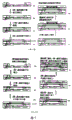
图1提供了若干比较常见之记忆卡图式。先前技术之缺点在于因为受到打线接合(wire bonding)外形的限制,令其难以提供较薄的封装。 采用打线接合堆栈(W/B stacking)时,由于晶粒堆栈中间需要空间加上需要模具来保护芯片与电线,因此在提供较薄的封装上有相当程度的困难。相关制程包含了模具灌模(胶)法(molding injection)或液体印刷法(liquid printing)。其引发了关于良率的问题。Micro SD卡所需要的整体厚度为0.7mm+/-0.1mm。Figure 1 provides some common memory card diagrams. The disadvantage of the prior art is that it is difficult to provide a thinner package due to the limitation of the shape of the wire bonding. When using wire bonding stacking (W/B stacking), it is quite difficult to provide a thinner package due to the space required in the middle of the die stack and the need for a mold to protect the chip and wires. Related processes include mold filling (glue) method (molding injection) or liquid printing method (liquid printing). It raises questions about yield. The required overall thickness of Micro SD card is 0.7mm+/-0.1mm.
因此,目前所需要的系具有可解决上述封装厚度问题并拥有简易制程之高阶记忆卡结构。Therefore, what is needed at present is a high-level memory card structure that can solve the above-mentioned packaging thickness problem and has a simple manufacturing process.
发明内容Contents of the invention
本发明之一目的系在于提供一种超薄及小尺寸(small formfactor)的记忆卡。One object of the present invention is to provide an ultra-thin and small formfactor memory card.
本发明之另一目的系在于提供一种拥有简易制程以及低成本方案的可靠产品。Another object of the present invention is to provide a reliable product with a simple manufacturing process and a low-cost solution.
记忆卡的结构包含了一上表面具有晶粒容纳凹槽之基底、一通孔结构及形成于基底之布线。一第一晶粒配置于晶粒容纳凹槽。一第一介电层形成于第一晶粒与基底之上。一第一重布层(re-distribution layer,RDL)形成于第一介电层上,其中第一重布层系耦合至第一晶粒与布线。一第二介电层形成于第一重布层上。一第二晶粒配置于第二介电层之上。一第三介电层形成于第二介电层与第二晶粒上。一第二重布层形成于第三介电层上,其中第二重布层系耦合至第二晶粒与第一重布层。一第四介电层形成于第二重布层上。一第三晶粒形成于第四介电层之上并耦合至第二重布层。一第五介电层形成于第三晶粒周围(当第三晶粒系采用覆晶形式(flip chip type)时,此步骤可略过),并由一塑胶盖罩住第一、第二及第三晶粒。The structure of the memory card includes a substrate with crystal grain containing grooves on the upper surface, a through-hole structure and wiring formed on the substrate. A first die is disposed in the die receiving groove. A first dielectric layer is formed on the first crystal grain and the substrate. A first re-distribution layer (re-distribution layer, RDL) is formed on the first dielectric layer, wherein the first re-distribution layer is coupled to the first die and the wiring. A second dielectric layer is formed on the first redistribution layer. A second crystal grain is disposed on the second dielectric layer. A third dielectric layer is formed on the second dielectric layer and the second crystal grain. A second redistribution layer is formed on the third dielectric layer, wherein the second redistribution layer is coupled to the second die and the first redistribution layer. A fourth dielectric layer is formed on the second redistribution layer. A third die is formed on the fourth dielectric layer and coupled to the second RDL. A fifth dielectric layer is formed around the third die (this step can be skipped when the third die adopts flip chip type), and a plastic cover covers the first and second dies. and the third grain.
另外包含了被动组件(passive device)形成于该第四介电层上。在一实施例中, 第三晶粒系由覆晶配置法(flip chipconfiguration)所形成的。在另一实施例中,第三晶粒系连结于该第四介电层之上,而第三重布层系形成于第五介电层上并耦合至该第二重布层。In addition, a passive device is formed on the fourth dielectric layer. In one embodiment, the third die is formed by flip chip configuration. In another embodiment, a third die is connected on the fourth dielectric layer, and a third redistribution layer is formed on the fifth dielectric layer and coupled to the second redistribution layer.
第一、第二、第三、第四及第五介电层其中之一包含一弹性介电层(elastic dielectric layer)。第一、第二、第三、第四及第五介电层其中之一包含一以硅介电(silicone dielectric)为主的材质、苯环丁烯(benzo-cyclo-butene,BCB)或聚酰亚胺(polyimide,PI)。以硅介电为主的材质包含了硅氧烷聚合物(SINR)、硅氧化物、硅氮化物或其合成物。第一、第二、第三、第四及第五介电层其中之一包含一感光层(photosensitivelayer)。由第一及第二晶粒扩散出(fan out)第一及第二重布层。One of the first, second, third, fourth and fifth dielectric layers includes an elastic dielectric layer. One of the first, second, third, fourth and fifth dielectric layers comprises a silicon dielectric (silicone dielectric)-based material, benzo-cyclo-butene (benzo-cyclo-butene, BCB) or poly imide (polyimide, PI). Silicon-based dielectric materials include siloxane polymers (SINR), silicon oxides, silicon nitrides, or composites thereof. One of the first, second, third, fourth and fifth dielectric layers includes a photosensitive layer. The first and second redistribution layers are fanned out from the first and second dies.
附图说明Description of drawings
图1系为根据先前技术之记忆卡结构之剖面图。Fig. 1 is a cross-sectional view of a structure of a memory card according to the prior art.
图2系为根据本发明之基底结构之剖面图。Fig. 2 is a cross-sectional view of a base structure according to the present invention.
图3系为根据本发明之结构之剖面图。Figure 3 is a cross-sectional view of a structure according to the invention.
图4系为根据本发明之结构之剖面图。Figure 4 is a cross-sectional view of a structure according to the invention.
图5(a)-(i)系为根据本发明之记忆卡制程之流程图。5(a)-(i) are flow charts of the memory card manufacturing process according to the present invention.
图6系为根据本发明之结构之剖面图。Figure 6 is a cross-sectional view of a structure according to the present invention.
图7系为根据本发明之结构之剖面图。Fig. 7 is a cross-sectional view of a structure according to the present invention.
图8系为根据本发明之结构之剖面图。Figure 8 is a cross-sectional view of a structure according to the present invention.
图中:In the picture:
2基底 28黏着性材质2
4晶粒容纳凹槽 30第三介电层4 Die receiving
6布线 32第二重布层6
8通孔 34第四介电层8 through
10第一晶粒 36输入/输出垫10 first die 36 input/output pads
12黏着性材质 38第三晶粒12
14输入/输出垫 40被动组件14 Input/
16接触垫 42顶层16
18第一介电层 44通孔18 first dielectric layer 44 through holes
20第一重布层 48第五介电层20 the
22填充材质 50第三重布层22
24第二介电层 54预形成之塑胶盖24
26第二晶粒 56端点垫26
具体实施方式Detailed ways
本发明将配合其较佳实施例与后附之图式详述于下。应可理解,本发明中之较佳实施例系仅用以说明,而非用以限定本发明。此外,除文中之较佳实施例外,本发明亦可广泛应用于其它实施例,并且本发明并不限定于任何实施例,而应视后附之申请专利范围而定。The present invention will be described in detail below in conjunction with its preferred embodiments and the accompanying drawings. It should be understood that the preferred embodiments of the present invention are only used for illustration rather than limiting the present invention. In addition, except for the preferred embodiments herein, the present invention can also be widely applied to other embodiments, and the present invention is not limited to any embodiment, but should be determined by the scope of the appended patent application.
本发明揭露一种晶圆级封装(wafer level package,WLP)之结构,其基底具有预定凹槽,并有通孔形成于基底。感光层系涂布于晶粒及预形成基底之上。较佳的情况下,感光层之材料系由弹性材料所形成。The invention discloses a wafer level package (wafer level package, WLP) structure, the base of which has predetermined grooves, and through holes are formed in the base. The photosensitive layer is coated on the die and the preformed substrate. Preferably, the photosensitive layer is made of elastic material.
图2系为预形成之基底,图3及图4系为记忆卡之结构,而图5则系根据本发明所实施的一例之流程。如图2、图3以及图5(a)所示,此结构包含具有晶粒容纳凹槽4之基底2得以配置晶粒。复数的通孔8以及布线6设计于基底2之中或之上。通孔8系形成于基底2之上表面至基底2之下表面。一导电材质将填入于通孔8之中以利电子连接。一端点垫56形成于基底2之下表面。Fig. 2 is a pre-formed substrate, Fig. 3 and Fig. 4 are the structure of a memory card, and Fig. 5 is a process according to an example of the present invention. As shown in FIG. 2 , FIG. 3 and FIG. 5( a ), this structure includes a
一第一晶粒10系配置于基底2的晶粒容纳凹槽4之中并藉由黏着性材质12加以固定。如熟知该项技术者所熟知,接触垫(连接垫(bonding pads))14系形成于晶粒10之上,而接触垫16则形成于基底2之上。填充材质22系装填于晶粒及晶粒容纳凹槽4侧壁间之空隙,此填充材质可与上述之黏着性材质12相同。一感光层(photosensitive layer)或介电层18系形成于晶粒之上并填入晶粒10以及晶粒容纳凹槽4墙壁间之空隙(以保持相同之表面层)。于微影制程(lithography process)或曝光制程(exposure procedure)中,复数开口将形成于介电层18之内。复数开口系分别经由通孔8对准(aligned)接触,以及对准接触或输入/输出垫(I/O pad)14。重布层(re-distribution layer,RDL)20,亦可称为金属布线,系藉由移除部份形成于介电层18上之金属层而形成于介电层18之上,其中重布层20系藉由输入/输出垫14以与晶粒10保持电性连接(electricallyconnected)。部份重布层之材质将重新填入介电层18之开口,因此藉由通孔8上的金属以及垫16上的金属而形成接触。如图3以及图5(c)所示,另一介电层24系覆盖于重布层20之上。A
请参照图3以及图5(d)-(e),介电层18系形成于晶粒10以及基底之顶上并填满晶粒2周遭的空间。一第二晶粒26系藉由黏着性材质28而装配于第二介电层24之上。同样地,第三介电层或感光层30系形成于第二晶粒26之上并填入邻接晶粒26之空间。于微影制程或曝光制程中,复数开口将形成于介电层30之内。复数开口系分别经由第二晶粒26之输入/输出垫36而对准接触。一第二重布层32,系藉由移除部份形成于介电层上之金属层而形成于第三介电层30之上,其中重布层32系藉由输入/输出垫36以与第二晶粒26保持电性连接。一第四介电层34覆盖于第二重布层32之上。复数开口形成于第四介电层34中。Referring to FIG. 3 and FIG. 5( d )-( e ), the
请参照图3以及图5(f)-(g),一第三晶粒38系装配于第四介电层34之上并藉由第四介电层34之开口以及第三晶粒38之凸块而耦合至第二重布层32。较佳的情况下,第三晶粒38系藉由覆晶配置法(flip chip configuration)而耦合。另外,至少一被动组件(passive device)40可藉由表面黏着技术(surfacemount technology,SMT)耦合至第二重布层32。最后,一顶层42系被形成来覆盖住被动组件40并至少包围住第三晶粒38(在本发明中,此过程系可略过)。在一实施例中,晶粒38之上表面得为无遮蔽,以藉此减少厚度并增强散热(thermal dissipation)效果。第二重布层32系藉由通孔结构44与第一重布层20相连。在另一情况下,如图6及图5(h)-(i)所示,第三晶粒38并非藉由覆晶配置法而系藉由黏着性材质4 6装配于第二重布层上。一第五介电层48系被形成来覆盖被动组件40以及第三晶粒38。一第三重布层50系形成于第五介电层48上并连结至第三晶粒、被动组件以及第二重布层32。如图5(h)-(i)所示,一顶层52系形成于第三重布层50之上。由于其它结构与图5(a)-(e)相似,因此省略了相关叙述。图4及图7标明了记忆卡结构的尺寸,如图所示,a:底层基底厚度;b:具有开放凹槽之上基底厚度;c:增层后之第二晶粒厚度;d:FC/SMT后之第三晶粒厚度;e:基底之接触金属厚度~25μm;预形成之基底厚度a+b+c=300μm。本发明之尺寸较先前技术之尺寸为薄。Please refer to FIG. 3 and FIG. 5 (f)-(g), a
图8描述了记忆卡之最终结构。一预形成之塑胶盖54罩住众多晶粒。标志可以标于上盖之上,锡球罩幕(solder mask)则形成于封装结构之下藉以露出端点垫56。Figure 8 depicts the final structure of the memory card. A preformed
较佳的情况下,基底2之材料系为有机基底例如FR5、BT、FR4、具有已定义凹槽(defined cavity)之印刷电路板(PCB)或具有预蚀刻电路(pre-etching circuit)之Alloy42。具有高玻璃化转变温度(glass transition temperature,Tg)之有机基底系为环氧化物型(epoxy type)FR5或BT(Bismaleimide triazine)型基底。Alloy42系由镍(42%)以及铁(58%)所组成。也可使用柯华合金(Kovar),其成份为镍(29%)、钴(17%)以及铁(54%)。玻璃、陶瓷、硅亦可做为基底。凹槽4之厚度可以比晶粒10稍微厚一点。而深度也可以更深一点。Preferably, the material of the
基底可为圆形(round type),例如晶圆型(wafer type),且其直径(diameter)可为200、300mm或更高。也可以采用矩形(rectangular type),例如面板型(panel form)。在本发明之一实施例中,本发明之介电层在较佳情况下系以硅介电(siliconedielectric)为主之弹性材质,其包含硅氧烷聚合物(SINR)、硅氧化物、硅氮化物或其合成物。在另一实施例中,介电层系由包含苯环丁烯(BCB)、环氧化物(epoxy)、聚酰亚胺(PI)或树脂。在较佳的情况下,为了制程的简便,其将采用感光层。The substrate can be of round type, such as wafer type, and its diameter can be 200, 300mm or higher. A rectangular type, such as a panel form, can also be used. In one embodiment of the present invention, the dielectric layer of the present invention is preferably an elastic material based on silicon dielectric (siliconedielectric), which includes siloxane polymer (SINR), silicon oxide, silicon Nitride or its compound. In another embodiment, the dielectric layer is made of benzocyclobutene (BCB), epoxy, polyimide (PI) or resin. In a preferred situation, a photosensitive layer will be used for the simplicity of the manufacturing process.
在本发明之一实施例中,上述弹性介电层系为一种热膨胀系数(CTE)大于100(ppm/℃)、延伸速率(elongation rate)约40%(较佳的为30%至50%)及硬度(hardness)介于塑胶与橡胶间之材质。弹性介电层18之厚度系依照温度循环试验(temperaturecycling test)期间重布层/介电层界面中所累积之应力(stress)而决定。In one embodiment of the present invention, the above-mentioned elastic dielectric layer system is one with a coefficient of thermal expansion (CTE) greater than 100 (ppm/°C) and an elongation rate of about 40% (preferably 30% to 50%) ) and hardness (hardness) between plastic and rubber material. The thickness of the
在本发明之一实施例中,重布层之材质包含钛/铜/金合金(Ti/Cu/Au alloy)或钛/铜/镍/金合金(Ti/Cu/Ni/Au alloy);重布层之厚度系介于2μm及15μm之间。钛/铜合金(Ti/Cu alloy)系利用溅镀(sputtering)技术所形成,例如晶种金属层(seedmetal layers),而铜/金(Cu/Au)或铜/镍/金合金(Cu/Ni/Aualloy)系由电镀(electroplating)技术所形成,利用电镀制程形成重布层可使重布层具有足够之厚度以容忍温度循环期间之热膨胀系数不相符(mismatching)。金属垫可为铝或铜或其组合。In one embodiment of the present invention, the material of the redistribution layer includes titanium/copper/gold alloy (Ti/Cu/Au alloy) or titanium/copper/nickel/gold alloy (Ti/Cu/Ni/Au alloy); The thickness of the cloth layer is between 2 μm and 15 μm. Titanium/copper alloy (Ti/Cu alloy) is formed by sputtering technology, such as seed metal layers, while copper/gold (Cu/Au) or copper/nickel/gold alloy (Cu/ Ni/Aualloy) is formed by electroplating technology. Using the electroplating process to form the redistribution layer can make the redistribution layer have sufficient thickness to tolerate the mismatching of the thermal expansion coefficient during the temperature cycle. The metal pads can be aluminum or copper or a combination thereof.
如图2(a)-(g)所示,重布层系由晶粒扩散,并且往下与布线6连接。连接布线系经由通孔8穿过基底2。因此可缩减晶粒封装之厚度。本发明之封装将较先前技术为薄。再者,基底系于封装前预先形成。凹槽4以及布线6也系预先形成的。因此,生产率(throughput)可较以往更为增进。本发明揭露一种不需在重布层上堆栈增层(built-up layers)之扩散式晶圆级封装(WLP)技术。As shown in Figure 2(a)-(g), the redistribution layer is diffused from the grains and connected to the wiring 6 downward. The connection wiring passes through the
本发明之优点详述如下:The advantages of the present invention are described in detail as follows:
超薄封装及小尺寸(small form factor):封装之厚度系约450μm至600μm,而封装尺寸(form factor)可以只较芯片尺寸稍微大一点。其可轻易控制包含塑胶盖之完成品之总厚度。晶粒之厚度可控制在约50μm至100μm,并可藉由在封装内堆栈晶粒而达成较高密度之内存。Ultra-thin package and small form factor: The thickness of the package is about 450 μm to 600 μm, and the package size (form factor) can only be slightly larger than the chip size. It can easily control the overall thickness of the finished product including the plastic cover. The thickness of the die can be controlled at about 50 μm to 100 μm, and a higher density memory can be achieved by stacking the die in the package.
较可靠的产品:芯片系完整包装于封装内。至少100μm厚之环氧化物材质形成于芯片的两面。芯片系配置于凹槽中,而弹性材质则充填于芯片周围及凹槽壁面之中,用以吸收芯片及基底(FR5之热膨胀系数约为17至20)之间热膨胀系数不相符所产生之机械应力(mechanical stress)。再者,介电层系采用弹性材质故可以吸收温度循环期间之机械应力。芯片可以堆栈在第一芯片上,解决热膨胀系数不相符的问题。More reliable product: the chip is completely packaged in the package. An epoxy material with a thickness of at least 100 μm is formed on both sides of the chip. The chip is arranged in the groove, and the elastic material is filled around the chip and in the wall of the groove to absorb the mechanical force caused by the mismatch of thermal expansion coefficient between the chip and the substrate (FR5 thermal expansion coefficient is about 17 to 20). Stress (mechanical stress). Furthermore, the dielectric layer is made of elastic material so it can absorb the mechanical stress during the temperature cycle. Chips can be stacked on the first chip to solve the problem of inconsistent thermal expansion coefficients.
简易制程以及低成本方案:本发明利用具有晶粒容纳凹槽之基底(FR5)以及其中所形成之电路。块板(piece panel)或批次式(batch type)之「封装」制造系采用增层(build-up layers)步骤。晶粒系藉由板面连结(panel bonding)步骤装配以提供较高的准确性。封装之分割系采用晶粒切割步骤(dicing saw process)来使「封装」分离。并采用一预形成之塑胶盖以完成最终产品。本发明可根据板面层级(panel level)来测试FGS产品以降低测试成本。Simple manufacturing process and low-cost solution: The present invention utilizes a substrate (FR5) with die receiving grooves and circuits formed therein. Piece panel or batch type "package" manufacturing uses build-up layers. Die systems are assembled by panel bonding steps to provide higher accuracy. The separation of the package is to use the dicing saw process to separate the "package". And use a pre-formed plastic cover to complete the final product. The present invention can test FGS products according to the panel level to reduce the test cost.
本发明以较佳实施例说明如上,然其并非用以限定本发明所主张之专利权利范围。其专利保护范围当视后附之申请专利范围及其等同领域而定。凡熟悉此领域之技艺者,在不脱离本专利精神或范围内,所作之更动或润饰,均属于本发明所揭示精神下所完成之等效改变或设计,且应包含在下述之申请专利范围内。The present invention is described above with preferred embodiments, but it is not intended to limit the scope of patent rights claimed by the present invention. The scope of its patent protection shall depend on the scope of the appended patent application and its equivalent fields. Those who are familiar with the skills in this field, without departing from the spirit or scope of this patent, make changes or modifications, all belong to the equivalent change or design completed under the spirit disclosed by the present invention, and should be included in the following patent application within range.
Claims (10)
Applications Claiming Priority (2)
| Application Number | Priority Date | Filing Date | Title |
|---|---|---|---|
| US11/624,629 | 2007-01-18 | ||
| US11/624,629 US20080174008A1 (en) | 2007-01-18 | 2007-01-18 | Structure of Memory Card and the Method of the Same |
Publications (1)
| Publication Number | Publication Date |
|---|---|
| CN101231709A true CN101231709A (en) | 2008-07-30 |
Family
ID=39640450
Family Applications (1)
| Application Number | Title | Priority Date | Filing Date |
|---|---|---|---|
| CNA2008100007931A Pending CN101231709A (en) | 2007-01-18 | 2008-01-17 | Structure of memory card and method thereof |
Country Status (3)
| Country | Link |
|---|---|
| US (1) | US20080174008A1 (en) |
| CN (1) | CN101231709A (en) |
| TW (1) | TW200834877A (en) |
Cited By (7)
| Publication number | Priority date | Publication date | Assignee | Title |
|---|---|---|---|---|
| CN101719484B (en) * | 2008-10-09 | 2012-03-14 | 台湾积体电路制造股份有限公司 | Backside connection to tsvs having redistribution lines |
| CN103545288A (en) * | 2012-07-13 | 2014-01-29 | 英特尔移动通信有限责任公司 | Stacked fan-out semiconductor chip |
| CN103681606A (en) * | 2012-08-29 | 2014-03-26 | 台湾积体电路制造股份有限公司 | Three dimensional (3D) fan-out packaging mechanisms |
| CN104392937A (en) * | 2013-06-28 | 2015-03-04 | 英特尔公司 | Method to increase i/o density and reduce layer counts in bbul packages |
| CN105280615A (en) * | 2014-06-11 | 2016-01-27 | 旺宏电子股份有限公司 | A multi-chip package structure and method for preparing the multi-chip package |
| CN106531644A (en) * | 2016-12-09 | 2017-03-22 | 华进半导体封装先导技术研发中心有限公司 | Packaging process and packaging structure for chip |
| CN106783748A (en) * | 2016-12-09 | 2017-05-31 | 华进半导体封装先导技术研发中心有限公司 | The packaging technology and encapsulating structure of a kind of chip |
Families Citing this family (32)
| Publication number | Priority date | Publication date | Assignee | Title |
|---|---|---|---|---|
| KR100836663B1 (en) * | 2006-02-16 | 2008-06-10 | 삼성전기주식회사 | Cavity formed package-on package and method for manufacturing same |
| TW200743035A (en) * | 2006-05-09 | 2007-11-16 | Siliconware Precision Industries Co Ltd | Circuit card module and method for fabricating the same |
| TWI360207B (en) | 2007-10-22 | 2012-03-11 | Advanced Semiconductor Eng | Chip package structure and method of manufacturing |
| US20090230554A1 (en) * | 2008-03-13 | 2009-09-17 | Broadcom Corporation | Wafer-level redistribution packaging with die-containing openings |
| TWI453877B (en) * | 2008-11-07 | 2014-09-21 | 日月光半導體製造股份有限公司 | Buried chip package structure and process |
| US8114708B2 (en) * | 2008-09-30 | 2012-02-14 | General Electric Company | System and method for pre-patterned embedded chip build-up |
| US9875911B2 (en) | 2009-09-23 | 2018-01-23 | STATS ChipPAC Pte. Ltd. | Semiconductor device and method of forming interposer with opening to contain semiconductor die |
| US8143097B2 (en) * | 2009-09-23 | 2012-03-27 | Stats Chippac, Ltd. | Semiconductor device and method of forming open cavity in TSV interposer to contain semiconductor die in WLCSMP |
| US8569894B2 (en) | 2010-01-13 | 2013-10-29 | Advanced Semiconductor Engineering, Inc. | Semiconductor package with single sided substrate design and manufacturing methods thereof |
| US8320134B2 (en) | 2010-02-05 | 2012-11-27 | Advanced Semiconductor Engineering, Inc. | Embedded component substrate and manufacturing methods thereof |
| US8618654B2 (en) * | 2010-07-20 | 2013-12-31 | Marvell World Trade Ltd. | Structures embedded within core material and methods of manufacturing thereof |
| TWI411075B (en) | 2010-03-22 | 2013-10-01 | 日月光半導體製造股份有限公司 | Semiconductor package and method of manufacturing same |
| TWI426587B (en) * | 2010-08-12 | 2014-02-11 | 矽品精密工業股份有限公司 | Wafer size package and its preparation method |
| US9406658B2 (en) | 2010-12-17 | 2016-08-02 | Advanced Semiconductor Engineering, Inc. | Embedded component device and manufacturing methods thereof |
| US8487426B2 (en) | 2011-03-15 | 2013-07-16 | Advanced Semiconductor Engineering, Inc. | Semiconductor package with embedded die and manufacturing methods thereof |
| US8546900B2 (en) * | 2011-06-09 | 2013-10-01 | Optiz, Inc. | 3D integration microelectronic assembly for integrated circuit devices |
| US20130040423A1 (en) | 2011-08-10 | 2013-02-14 | Taiwan Semiconductor Manufacturing Company, Ltd. | Method of Multi-Chip Wafer Level Packaging |
| US8754514B2 (en) * | 2011-08-10 | 2014-06-17 | Taiwan Semiconductor Manufacturing Company, Ltd. | Multi-chip wafer level package |
| US9620580B2 (en) * | 2013-10-25 | 2017-04-11 | Mediatek Inc. | Semiconductor structure |
| US9527723B2 (en) | 2014-03-13 | 2016-12-27 | STATS ChipPAC Pte. Ltd. | Semiconductor device and method of forming microelectromechanical systems (MEMS) package |
| US9601463B2 (en) * | 2014-04-17 | 2017-03-21 | Taiwan Semiconductor Manufacturing Company, Ltd. | Fan-out stacked system in package (SIP) and the methods of making the same |
| US9978729B2 (en) * | 2015-03-06 | 2018-05-22 | Mediatek Inc. | Semiconductor package assembly |
| KR102549402B1 (en) | 2016-08-04 | 2023-06-28 | 삼성전자주식회사 | Semiconductor package and method for fabricating the same |
| US10672741B2 (en) * | 2016-08-18 | 2020-06-02 | Taiwan Semiconductor Manufacturing Company, Ltd. | Semiconductor packages with thermal-electrical-mechanical chips and methods of forming the same |
| US11081448B2 (en) | 2017-03-29 | 2021-08-03 | Intel Corporation | Embedded die microelectronic device with molded component |
| WO2019066945A1 (en) | 2017-09-29 | 2019-04-04 | Intel IP Corporation | Integrating and accessing passive components in wafer-level packages |
| KR102491103B1 (en) | 2018-02-06 | 2023-01-20 | 삼성전자주식회사 | Semiconductor package and method of fabricating the same |
| CN108831876B (en) * | 2018-08-10 | 2024-03-08 | 浙江熔城半导体有限公司 | Packaging structure with holes embedded in filter chip and manufacturing method thereof |
| KR102653213B1 (en) | 2019-05-13 | 2024-04-01 | 삼성전기주식회사 | Semiconductor package |
| US11088125B2 (en) | 2019-09-17 | 2021-08-10 | Taiwan Semiconductor Manufacturing Company, Ltd. | IPD modules with flexible connection scheme in packaging |
| US12322726B2 (en) * | 2022-03-01 | 2025-06-03 | Taiwan Semiconductor Manufacturing Company, Ltd. | Method of forming an integrated circuit package having a padding layer on a carrier |
| US20240339370A1 (en) * | 2023-04-06 | 2024-10-10 | Taiwan Semiconductor Manufactoring Co., Ltd. | Packaging of Dies Including TSVs using Sacrificial Carrier |
-
2007
- 2007-01-18 US US11/624,629 patent/US20080174008A1/en not_active Abandoned
-
2008
- 2008-01-17 TW TW097101851A patent/TW200834877A/en unknown
- 2008-01-17 CN CNA2008100007931A patent/CN101231709A/en active Pending
Cited By (7)
| Publication number | Priority date | Publication date | Assignee | Title |
|---|---|---|---|---|
| CN101719484B (en) * | 2008-10-09 | 2012-03-14 | 台湾积体电路制造股份有限公司 | Backside connection to tsvs having redistribution lines |
| CN103545288A (en) * | 2012-07-13 | 2014-01-29 | 英特尔移动通信有限责任公司 | Stacked fan-out semiconductor chip |
| CN103681606A (en) * | 2012-08-29 | 2014-03-26 | 台湾积体电路制造股份有限公司 | Three dimensional (3D) fan-out packaging mechanisms |
| CN104392937A (en) * | 2013-06-28 | 2015-03-04 | 英特尔公司 | Method to increase i/o density and reduce layer counts in bbul packages |
| CN105280615A (en) * | 2014-06-11 | 2016-01-27 | 旺宏电子股份有限公司 | A multi-chip package structure and method for preparing the multi-chip package |
| CN106531644A (en) * | 2016-12-09 | 2017-03-22 | 华进半导体封装先导技术研发中心有限公司 | Packaging process and packaging structure for chip |
| CN106783748A (en) * | 2016-12-09 | 2017-05-31 | 华进半导体封装先导技术研发中心有限公司 | The packaging technology and encapsulating structure of a kind of chip |
Also Published As
| Publication number | Publication date |
|---|---|
| TW200834877A (en) | 2008-08-16 |
| US20080174008A1 (en) | 2008-07-24 |
Similar Documents
| Publication | Publication Date | Title |
|---|---|---|
| CN101231709A (en) | Structure of memory card and method thereof | |
| US9691696B2 (en) | Interposers with circuit modules encapsulated by moldable material in a cavity, and methods of fabrication | |
| CN102569214B (en) | Three-dimensional system-in-package stacked package structure | |
| TWI352413B (en) | Semiconductor device package with die receiving th | |
| US7459729B2 (en) | Semiconductor image device package with die receiving through-hole and method of the same | |
| US6593220B1 (en) | Elastomer plating mask sealed wafer level package method | |
| KR101387706B1 (en) | Semiconductor Package, Method of Fabricating the Same and Electronic Device Including the Same | |
| CN101207099B (en) | Dielectric layer structure in wafer level packaging build-up layer | |
| TWI358814B (en) | Semiconductor device package having multi-chips wi | |
| US20080083980A1 (en) | Cmos image sensor chip scale package with die receiving through-hole and method of the same | |
| US20060216868A1 (en) | Package structure and fabrication thereof | |
| CN101261984A (en) | Semiconductor assembly packaging structure and method thereof | |
| CN101325188A (en) | Wafer level semiconductor package with double-sided build-up and method thereof | |
| CN104637908A (en) | Semiconductor package and method of manufacturing the semiconductor package | |
| JP2002057241A (en) | Semiconductor package including implantable conductive pattern and method of manufacturing the same | |
| KR101863850B1 (en) | Integrated circuit packaging system with dual side connection and method of manufacture thereof | |
| JP2008244437A (en) | Image sensor package with die receiving opening and method thereof | |
| CN101202253A (en) | Wafer level package with good thermal expansion coefficient efficiency and method thereof | |
| CN101221936A (en) | Wafer level package with die-in-via and method thereof | |
| TW200845343A (en) | Semiconductor device package having multi-chips with side-by-side configuration and the method of the same | |
| CN110783282A (en) | Package structure | |
| CN101252108A (en) | Semiconductor device package having die receiving via and connecting via and method thereof | |
| CN101335265A (en) | Semiconductor package structure with die function | |
| KR20080065871A (en) | Multi-chip stack package having a groove in the wiring board and method of manufacturing the same | |
| US20250201647A1 (en) | Package structure |
Legal Events
| Date | Code | Title | Description |
|---|---|---|---|
| C06 | Publication | ||
| PB01 | Publication | ||
| C10 | Entry into substantive examination | ||
| SE01 | Entry into force of request for substantive examination | ||
| C02 | Deemed withdrawal of patent application after publication (patent law 2001) | ||
| WD01 | Invention patent application deemed withdrawn after publication |