CN101183128B - Method and device for testing power capacity of duplexer - Google Patents
Method and device for testing power capacity of duplexer Download PDFInfo
- Publication number
- CN101183128B CN101183128B CN200710077433A CN200710077433A CN101183128B CN 101183128 B CN101183128 B CN 101183128B CN 200710077433 A CN200710077433 A CN 200710077433A CN 200710077433 A CN200710077433 A CN 200710077433A CN 101183128 B CN101183128 B CN 101183128B
- Authority
- CN
- China
- Prior art keywords
- power capacity
- point
- test
- loss difference
- insertion loss
- Prior art date
- Legal status (The legal status is an assumption and is not a legal conclusion. Google has not performed a legal analysis and makes no representation as to the accuracy of the status listed.)
- Expired - Fee Related
Links
Images


Landscapes
- Monitoring And Testing Of Transmission In General (AREA)
Abstract
本发明公开了一种双工器功率容量的测试方法和装置,其包括以下步骤:第一步、选择一位于双工器过渡带内的测试点,并记录该测试点与带内待测点的插入损耗差值;第二步、测试所述测试点的功率容量;第三步、计算所述插入损耗差值与第二步测得的功率容量的和,其和就是所述带内待测点的功率容量。本发明根据双工器的工作特性,通过测试过渡带某点的功率容量以及根据带内待测点和过渡带测试点的插入损耗差关系,间接的得到带内待测点的功率容量,克服了大功率容量的双工器测试时需要调整硬件输入设备(功放等)的麻烦,方便了模块测试,同时更大程度上降低了测试成本。
The invention discloses a method and device for testing the power capacity of a duplexer, which includes the following steps: the first step is to select a test point located in the transition zone of the duplexer, and record the test point and the point to be tested in the band The insertion loss difference; the second step, test the power capacity of the test point; the third step, calculate the sum of the insertion loss difference and the power capacity measured in the second step, and the sum is the in-band standby The power capacity of the measuring point. According to the working characteristics of the duplexer, the present invention indirectly obtains the power capacity of the point to be measured in the band by testing the power capacity of a certain point in the transition zone and according to the relationship between the insertion loss difference between the point to be tested in the band and the test point in the transition zone, and overcomes the problem of It eliminates the trouble of adjusting hardware input devices (power amplifiers, etc.) when testing duplexers with high power capacity, facilitates module testing, and reduces testing costs to a greater extent.
Description
技术领域technical field
本发明涉及一种移动通信领域射频模块测量方法和装置,更具体的说,是一种基于双工器功率容量的测试方法及其装置。The invention relates to a method and device for measuring a radio frequency module in the field of mobile communication, more specifically, a method and device for testing based on the power capacity of a duplexer.
背景技术Background technique
随着移动通信的快速发展,人们对移动通信业务信号的覆盖要求越来越高,除了根据网络规划布置相对比较密集的移动通讯设备外,还有一种就是在现有技术的基础上用尽量少的移动通讯设备来达到该目的。于是对移动通讯设备的发射功率有了比较高的要求,从而引发了对移动通讯设备中双工器功率容量的要求也越来越高,如何用一种比较简单通用的方法来测试大功率容量的双工器已经迫在眉睫。With the rapid development of mobile communication, people have higher and higher requirements for the coverage of mobile communication service signals. In addition to arranging relatively dense mobile communication equipment according to network planning, there is another way to use as little as possible on the basis of existing technologies. Mobile communication equipment to achieve this purpose. Therefore, there are relatively high requirements for the transmission power of mobile communication equipment, which leads to higher and higher requirements for the power capacity of duplexers in mobile communication equipment. How to use a relatively simple and general method to test high power capacity The duplexer is imminent.
在实际的双工器测试中,为了测试不同双工器的功率容量,在现有的测试方法中,测试时必须根据双工器的功率容量来更换/调整双工器输入激励信号的硬件设备,这样不仅给测试带来了很大的不便,更大程度上增加了测试成本。所以,就需要对其测试方法进行改进。In the actual duplexer test, in order to test the power capacity of different duplexers, in the existing test method, the hardware device of the duplexer input excitation signal must be replaced/adjusted according to the power capacity of the duplexer during the test , which not only brings great inconvenience to the test, but also increases the test cost to a greater extent. Therefore, it is necessary to improve its testing method.
发明内容Contents of the invention
为了克服现有技术中存在的不断更换测试硬件设备的问题和缺陷,本发明提供了一种双工器功率容量简单通用的测试方法和装置。为了解决上述问题,本发明采用如下技术方案。In order to overcome the problems and defects in the prior art of constantly replacing test hardware equipment, the present invention provides a simple and universal test method and device for duplexer power capacity. In order to solve the above problems, the present invention adopts the following technical solutions.
本发明的测试方法包括以下步骤:A、选择一位于双工器过渡带内的测试点,并记录该测试点与带内待测点的插入损耗差值;B、测试所述测试点的功率容量;C、计算所述插入损耗差值与步骤B测得的功率容量的和,其和就是所述带内待测点的功率容量。The test method of the present invention comprises the following steps: A, select a test point positioned at the duplexer transition zone, and record the insertion loss difference between the test point and the point to be tested in the band; B, test the power of the test point Capacity; C. Calculate the sum of the insertion loss difference and the power capacity measured in step B, and the sum is the power capacity of the point to be measured in the band.
其中,所述步骤A中,通过将待测量双工器的输入和输出端分别接入到插入损耗差测试设备上,来测量所述插入损耗差值。其中,所述步骤A中,根据待测量双工器的额定功率容量来选择位于双工器过渡带内的测试点。其中,所述步骤A中,所述测试点是位于过渡带内的任何一点,这个过渡带是指相位发生突变的点(即过渡带的截止点)与通带带外之间的区间。其中,所述步骤A中,所述带内待测点为待测量双工器的待测频率点,比如中心频率点。其中,所述步骤B中,通过功率容量测试设备来测量功率容量。其中,所述插入损耗差测试设备为矢量网络分析仪。Wherein, in the step A, the insertion loss difference is measured by respectively connecting the input and output ends of the duplexer to be measured to the insertion loss difference testing equipment. Wherein, in the step A, the test point located in the transition zone of the duplexer is selected according to the rated power capacity of the duplexer to be measured. Wherein, in the step A, the test point is any point located in the transition zone, and the transition zone refers to the interval between the point where the phase changes suddenly (ie, the cut-off point of the transition zone) and the outside of the passband. Wherein, in the step A, the in-band test point is a test frequency point of the duplexer to be measured, such as a center frequency point. Wherein, in the step B, the power capacity is measured by the power capacity testing equipment. Wherein, the insertion loss difference testing device is a vector network analyzer.
采用上述方法的装置,包括:功率容量测试设备,用于测试双工器带内某点的功率容量;插入损耗差测试设备,用于测试并获得双工器带内和过渡带两点的插入损耗差值;待测试双工器的输入、输出端分别通过一切换设备连接到所述功率容量测试设备和插入损耗差测试设备上。其中,所述切换设备可以采用射频开关用于自动切换,或者,所述切换设备为一连接线,用于手动切换待测试双工器与所述功率容量测试设备和插入损耗差测试设备的连接。The device using the above method includes: power capacity testing equipment, used to test the power capacity of a certain point in the duplexer band; insertion loss difference testing equipment, used to test and obtain the insertion of two points in the duplexer band and the transition band Loss difference: the input and output terminals of the duplexer to be tested are respectively connected to the power capacity testing equipment and the insertion loss difference testing equipment through a switching device. Wherein, the switching device can use a radio frequency switch for automatic switching, or the switching device is a connection line for manually switching the connection between the duplexer to be tested and the power capacity testing equipment and insertion loss difference testing equipment .
本发明的测试原理就是根据双工器的工作特性,通过测试过渡带某点的功率容量以及根据带内待测点和过渡带测试点的插入损耗差关系,间接的得到带内待测点的功率容量。相对于现有技术而言,采用本发明所述方法和装置,对于测试不同功率容量的双工器,选择一定能力的激励输出的硬件设备,就可以满足较大要求的双工器功率容量测试。所以,本发明可以降低大功率容量的双工器测试时对输入激励设备的要求,并且克服大功率容量的双工器测试时需要调整硬件输入设备(功率放大设备等)的麻烦,方便了模块测试,同时更大程度上降低了测试成本。The testing principle of the present invention is exactly according to the operating characteristics of the duplexer, by testing the power capacity of a certain point in the transition zone and according to the insertion loss difference relationship between the point to be tested in the band and the test point in the transition zone, indirectly obtain the power of the point to be tested in the band Power Capacity. Compared with the prior art, by using the method and device of the present invention, for testing duplexers with different power capacities, selecting a hardware device with a certain ability to stimulate output can meet the relatively large requirements of duplexer power capacity testing . Therefore, the present invention can reduce the requirement for input excitation equipment when duplexers with high power capacity are tested, and overcome the trouble of adjusting hardware input devices (power amplifiers, etc.) when testing duplexers with high power capacity, which facilitates the Test, while reducing the cost of testing to a greater extent.
附图说明Description of drawings
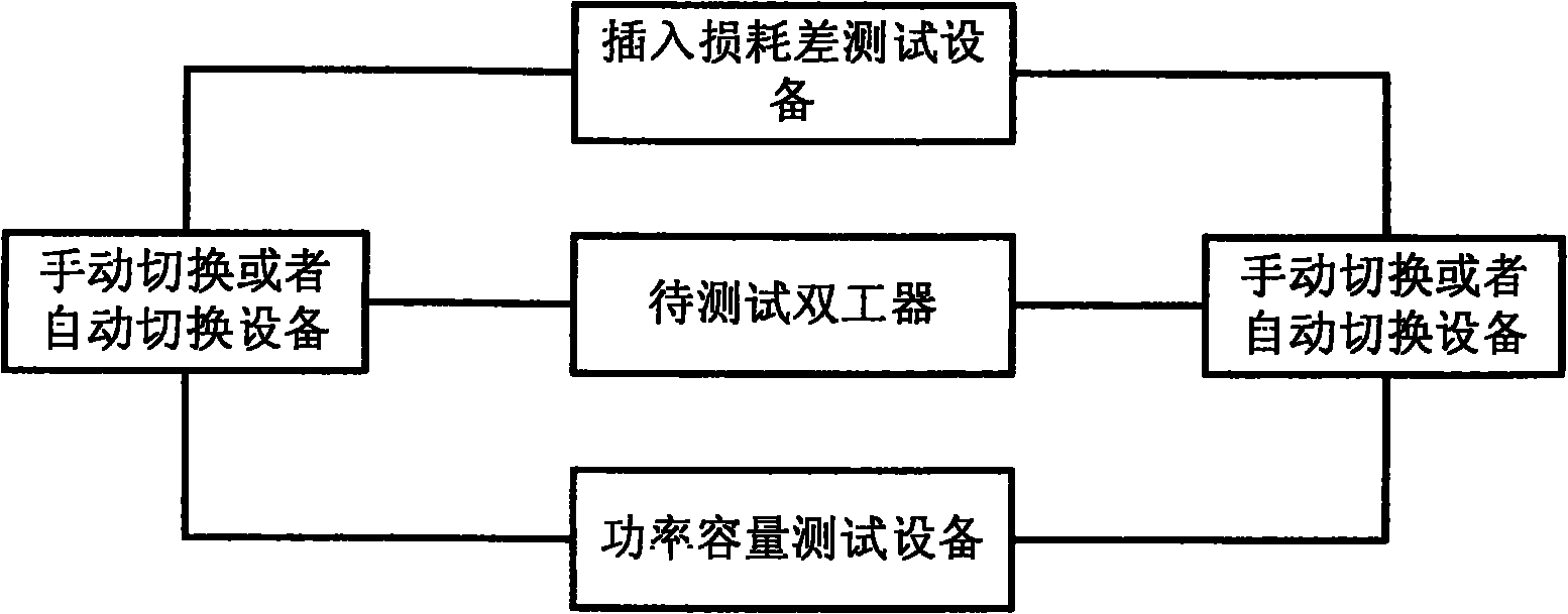
图1是本发明待测试双工器和所有测试设备之间的连接示意图。Fig. 1 is a schematic diagram of the connection between the duplexer to be tested and all test equipment in the present invention.
图2是具体实施方式中对功率容量为100W的双工器进行测试的装置结构图。Fig. 2 is a structural diagram of a device for testing a duplexer with a power capacity of 100W in a specific embodiment.
具体实施方式Detailed ways
下面具体描述本发明的各较佳实施例。Various preferred embodiments of the present invention are described in detail below.
如图1所示,本发明基于双工器的工作特性,提供了一种间接测量双工器功率容量的方法,其具体如下操作:As shown in Figure 1, the present invention provides a method for indirectly measuring the power capacity of a duplexer based on the operating characteristics of the duplexer, which specifically operates as follows:
第一步,将待测量双工器的输入和输出端分别接入到插入损耗差测试设备上,然后根据双工器的额定功率容量,选择一位于双工器过渡带内的测试B点(下一步的待测点),再记录B点与带内测试A点(需要测量数据的点,即通带带内的任一点)之间的插入损耗差值X1;The first step is to connect the input and output ends of the duplexer to be measured to the insertion loss difference test equipment respectively, and then select a test point B located in the transition zone of the duplexer according to the rated power capacity of the duplexer ( The point to be measured in the next step), and then record the insertion loss difference X1 between point B and point A of the in-band test (the point that needs to measure data, that is, any point in the passband);
第二步,通过手工切换或者自动切换设备进行切换,将双工器的输入和输出端分别接入到功率容量测试设备中,并对过渡带内的B点进行功率容量的测试,获得B点的功率容量X2;The second step is to switch by manual switching or automatic switching equipment, connect the input and output terminals of the duplexer to the power capacity test equipment respectively, and test the power capacity of point B in the transition zone to obtain point B The power capacity of X2;
第三步,将插入损耗差值X1加上第二步测得的功率容量X2,便得到带内测试A点的功率容量值。In the third step, the insertion loss difference X1 is added to the power capacity X2 measured in the second step to obtain the power capacity value of point A in the in-band test.
上述过程中,所述带内待测点A点可以是通带带内的任何一点,如待测量双工器的中心频率点,而选择的过渡带内的B点可以是在过渡带内任何一点,也就是指相位发生突变的点(即相位从正到负或从负到正的点)和通带带外之间的任一点,这里相位发生突变的点也指过渡带的截止点,上述插入损耗差测试设备和功率容量测试设备可以采用现有技术的方法和装置,如可以采用矢量网络分析仪来测量插入损耗差,而采用由信号源、功率放大器和功率计等来进行功率容量测试。In the above process, the point A to be measured in the band can be any point in the passband, such as the center frequency point of the duplexer to be measured, and the selected point B in the transition band can be any point in the transition band. One point refers to any point between the point where the phase changes suddenly (that is, the point where the phase changes from positive to negative or from negative to positive) and outside the passband, where the point where the phase changes suddenly also refers to the cut-off point of the transition band, The above-mentioned insertion loss difference test equipment and power capacity test equipment can adopt methods and devices of the prior art, such as a vector network analyzer can be used to measure the insertion loss difference, and the power capacity can be measured by a signal source, a power amplifier and a power meter, etc. test.
下面采用上述方法对功率容量为100W的双工器进行测试,其硬件测试设备按照图2所示的连接,这里的切换设备为一个单刀双掷射频开关,插入损耗差设备采用一台矢量网络分析仪,功率容量测试设备由信号源、最大能输出60W的功率放大器和一个功率计组成。The above-mentioned method is used to test a duplexer with a power capacity of 100W. The hardware test equipment is connected as shown in Figure 2. The switching device here is a single-pole double-throw RF switch, and the insertion loss difference device is analyzed by a vector network. The power capacity test equipment consists of a signal source, a power amplifier with a maximum output of 60W and a power meter.
先设置射频开关,使待测试双工器的输入和输出设备分别接到矢量网络分析仪的两端,确定过渡带内的测试B点,它与所要测试双工器的中心频率点A的插入损耗差为X1=3dB。接着,设置射频开关,使待测试双工器的输入和输出设备分别接到功率容量测试设备中,调节信号源输出信号功率的大小,通过观察功率计的读数来测试B点的功率容量,最后得到B点的功率容量为X2=55W(折合为47.4dBm)。最后,计算中心频率A点的功率容量为:X2+X1=47.4+3=50.4dBm,折合为:109.7W,这样便得到了A点的功率容量,从而也验证了A点的功率容量满足要求。First set up the RF switch, so that the input and output devices of the duplexer to be tested are respectively connected to the two ends of the vector network analyzer, and determine the test point B in the transition zone, which is inserted into the center frequency point A of the duplexer to be tested. The loss difference is X1=3dB. Then, set the RF switch, connect the input and output devices of the duplexer to be tested to the power capacity test equipment respectively, adjust the output signal power of the signal source, and test the power capacity of point B by observing the readings of the power meter, and finally The power capacity obtained at point B is X2=55W (equivalent to 47.4dBm). Finally, calculate the power capacity of point A at the center frequency: X2+X1=47.4+3=50.4dBm, equivalent to: 109.7W, so that the power capacity of point A is obtained, which also verifies that the power capacity of point A meets the requirements .
可见,本发明的方法通过间接测量的方法,避免了现有技术中采用直接测量而带来的需要根据双工器的功率容量来不时更换或调整硬件测试设备的麻烦,降低了测量成本,具有良好的应用前景。It can be seen that the method of the present invention avoids the trouble of changing or adjusting the hardware test equipment from time to time according to the power capacity of the duplexer brought by the direct measurement in the prior art through the indirect measurement method, reduces the measurement cost, and has the advantages of Good application prospects.
综上所述,本发明还提供了一双工器功率容量的测试装置,如图1和图2所示,其主要包括以下模块:In summary, the present invention also provides a test device for duplexer power capacity, as shown in Figure 1 and Figure 2, which mainly includes the following modules:
功率容量测试设备,用于负责测试双工器某点的功率容量,其可以采用常规方法,如图2所示,由信号源、功率放大器、功率计组成的装置;The power capacity testing equipment is used to be responsible for testing the power capacity of a certain point of the duplexer, which can adopt a conventional method, as shown in Figure 2, a device consisting of a signal source, a power amplifier, and a power meter;
插入损耗差测试设备,用于负责测试并得到双工器带内和过渡带两点的插入损耗差值,其可以进行测试点的选择并根据测试点记录插入损耗差。在具体测试时,该设备主要是根据相位变化特点(即正到负的突变)来选择合适的位于过渡带内的测试点,然后记录该测试点与要求的带内测试点之间的插入损耗差值;其可以用常规方法,如图2,由一台矢量网络分析器组成。The insertion loss difference test equipment is used to test and obtain the insertion loss difference between two points in the duplexer band and the transition zone, which can select the test point and record the insertion loss difference according to the test point. In the specific test, the device mainly selects the appropriate test point located in the transition zone according to the phase change characteristics (that is, the sudden change from positive to negative), and then records the insertion loss between the test point and the required in-band test point difference; it can be used in a conventional way, as shown in Figure 2, consisting of a vector network analyzer.
上述这两种测试设备之间的连接可以通过手工切换,如,先将连接到插入损耗差测试设备的电缆线拧下,然后通过电缆线将双工器的输入和输出端接到功率容量测试设备中;或者,也可以采用自动切换设备切换,如将待测试双工器的输入、输出端分别通过一自动切换设备连接到上述功率容量测试设备和插入损耗差测试设备上,该自动切换设备可以是射频开关,比如单刀双掷开关。The connection between the above two test equipment can be manually switched, for example, firstly unscrew the cable connected to the insertion loss difference test equipment, and then connect the input and output terminals of the duplexer to the power capacity test through the cable or, it is also possible to use automatic switching equipment switching, such as the input and output ends of the duplexer to be tested are respectively connected to the above-mentioned power capacity testing equipment and insertion loss difference testing equipment through an automatic switching equipment, the automatic switching equipment It may be a radio frequency switch, such as a single pole double throw switch.
上述各具体步骤的举例说明较为具体,并不能因此而认为是对本发明的专利保护范围的限制,本发明的专利保护范围应以所附权利要求为准。The illustrations of the above-mentioned specific steps are relatively specific, and cannot therefore be considered as limiting the scope of the patent protection of the present invention, and the scope of protection of the patent protection of the present invention should be determined by the appended claims.
Claims (10)
Priority Applications (1)
| Application Number | Priority Date | Filing Date | Title |
|---|---|---|---|
| CN200710077433A CN101183128B (en) | 2007-11-23 | 2007-11-23 | Method and device for testing power capacity of duplexer |
Applications Claiming Priority (1)
| Application Number | Priority Date | Filing Date | Title |
|---|---|---|---|
| CN200710077433A CN101183128B (en) | 2007-11-23 | 2007-11-23 | Method and device for testing power capacity of duplexer |
Publications (2)
| Publication Number | Publication Date |
|---|---|
| CN101183128A CN101183128A (en) | 2008-05-21 |
| CN101183128B true CN101183128B (en) | 2010-05-26 |
Family
ID=39448467
Family Applications (1)
| Application Number | Title | Priority Date | Filing Date |
|---|---|---|---|
| CN200710077433A Expired - Fee Related CN101183128B (en) | 2007-11-23 | 2007-11-23 | Method and device for testing power capacity of duplexer |
Country Status (1)
| Country | Link |
|---|---|
| CN (1) | CN101183128B (en) |
Families Citing this family (5)
| Publication number | Priority date | Publication date | Assignee | Title |
|---|---|---|---|---|
| CN103389459A (en) * | 2012-05-11 | 2013-11-13 | 四川优的科技有限公司 | Fuel switch testing system capable of converting duplex into half-duplex |
| CN106855593B (en) * | 2015-12-09 | 2020-01-31 | 北京铁路信号有限公司 | Transponder test board system and test method |
| CN110133365B (en) * | 2019-04-29 | 2021-09-17 | 广东石油化工学院 | Method and device for detecting switching event of load |
| CN110806507B (en) * | 2019-10-24 | 2023-01-10 | 成都飞机工业(集团)有限责任公司 | In-situ automatic test method for bundled radio frequency cable and LRM modular interface |
| CN113358947A (en) * | 2020-03-02 | 2021-09-07 | 上海特普瑞通讯科技有限公司 | Radio frequency device test system |
Citations (5)
| Publication number | Priority date | Publication date | Assignee | Title |
|---|---|---|---|---|
| US6066953A (en) * | 1994-12-01 | 2000-05-23 | Teradyne, Inc. | Architecture for RF signal automatic test equipment |
| DE19852080C1 (en) * | 1998-11-11 | 2000-08-17 | Trw Automotive Electron & Comp | Monitoring temperature of electronic component with losses, especially power device, involves detecting cooling body or coolant temperature after power loss change, adding computed difference value |
| CN1378724A (en) * | 1999-10-13 | 2002-11-06 | D.S.P.C技术有限公司 | Control of transmission power in communication system |
| CN2724306Y (en) * | 2004-08-18 | 2005-09-07 | 中兴通讯股份有限公司 | Radio frequency automatic detector |
| CN1845477A (en) * | 2005-07-06 | 2006-10-11 | 华为技术有限公司 | System and method for testing power capacity in actual environment |
-
2007
- 2007-11-23 CN CN200710077433A patent/CN101183128B/en not_active Expired - Fee Related
Patent Citations (5)
| Publication number | Priority date | Publication date | Assignee | Title |
|---|---|---|---|---|
| US6066953A (en) * | 1994-12-01 | 2000-05-23 | Teradyne, Inc. | Architecture for RF signal automatic test equipment |
| DE19852080C1 (en) * | 1998-11-11 | 2000-08-17 | Trw Automotive Electron & Comp | Monitoring temperature of electronic component with losses, especially power device, involves detecting cooling body or coolant temperature after power loss change, adding computed difference value |
| CN1378724A (en) * | 1999-10-13 | 2002-11-06 | D.S.P.C技术有限公司 | Control of transmission power in communication system |
| CN2724306Y (en) * | 2004-08-18 | 2005-09-07 | 中兴通讯股份有限公司 | Radio frequency automatic detector |
| CN1845477A (en) * | 2005-07-06 | 2006-10-11 | 华为技术有限公司 | System and method for testing power capacity in actual environment |
Non-Patent Citations (2)
| Title |
|---|
| 黄坤超.矢量网络分析仪的时域功能在天线测量中的应用.电视技术47 3.2007,47(3),189-191. |
| 黄坤超.矢量网络分析仪的时域功能在天线测量中的应用.电视技术47 3.2007,47(3),189-191. * |
Also Published As
| Publication number | Publication date |
|---|---|
| CN101183128A (en) | 2008-05-21 |
Similar Documents
| Publication | Publication Date | Title |
|---|---|---|
| CN100582801C (en) | A batch detection method and device for power amplifiers | |
| CN101094430B (en) | Calibrating run device and method for terminal in dual modes | |
| CN104519503B (en) | A kind of radio frequency link switching device for mobile communication terminal test | |
| CN203658537U (en) | Automatic test system for continuous wave radio frequency power amplifier | |
| CN103744010A (en) | An automatic testing system and an automatic testing method of a continuous wave radio frequency power amplifier | |
| CN101183128B (en) | Method and device for testing power capacity of duplexer | |
| CN101437317A (en) | Wireless radio frequency index verification apparatus and method for multi-mode mobile communication terminal | |
| CN102014415A (en) | Method for detecting base station feed system on line, base station system and antenna suite | |
| CN101478353A (en) | Radio frequency unit capable of being used in wireless communication base station radio frequency automatic test | |
| CN1996802B (en) | RF consistency testing system of the time division synchronization and code division multi-address access terminal | |
| US20120045998A1 (en) | Testing system and measuring method thereof for measuring wireless network signal | |
| CN105388466A (en) | Conditioning device for transmitting excitation signal in T/R assembly test system | |
| CN105873108A (en) | Test system for radio frequency conformance of LTE (long term evolution) terminal | |
| CN104880621A (en) | Self calibration passive intermodulation tester | |
| CN104378101B (en) | A kind of switching switch for lane testing, method and system | |
| CN103052109B (en) | Method and device for radio frequency consistency test of wireless communication terminal of public network | |
| CN107566056A (en) | A kind of multichannel T/R components phase conformance testing device and method | |
| KR100531619B1 (en) | Apparatus and method of receiving sensitivity measuring for communication system with receiving only path | |
| CN103067548B (en) | Mobile phone receives debug system and the method for the sensitivity of difference match circuit | |
| CN205179373U (en) | A intermodulation test system that is used for POI's multifrequency section to stride standard | |
| CN103051392B (en) | Method and device for intermodulation interference test of wireless communication terminal of private network | |
| CN206602526U (en) | A kind of multistation passive cross modulation test device | |
| CN216485244U (en) | Automatic test system for large-scale components | |
| CN107202929A (en) | A kind of method for measuring the loss of rectangular waveguide component | |
| CN206602525U (en) | A kind of intermodulation and radio-frequency power capacity tester |
Legal Events
| Date | Code | Title | Description |
|---|---|---|---|
| C06 | Publication | ||
| PB01 | Publication | ||
| C10 | Entry into substantive examination | ||
| SE01 | Entry into force of request for substantive examination | ||
| C14 | Grant of patent or utility model | ||
| GR01 | Patent grant | ||
| CF01 | Termination of patent right due to non-payment of annual fee |
Granted publication date: 20100526 Termination date: 20161123 |
|
| CF01 | Termination of patent right due to non-payment of annual fee |