CN101169080B - System and method for operating a multiple fuel engine - Google Patents
System and method for operating a multiple fuel engine Download PDFInfo
- Publication number
- CN101169080B CN101169080B CN2007101678835A CN200710167883A CN101169080B CN 101169080 B CN101169080 B CN 101169080B CN 2007101678835 A CN2007101678835 A CN 2007101678835A CN 200710167883 A CN200710167883 A CN 200710167883A CN 101169080 B CN101169080 B CN 101169080B
- Authority
- CN
- China
- Prior art keywords
- fuel
- valve
- cylinder
- engine
- timing
- Prior art date
- Legal status (The legal status is an assumption and is not a legal conclusion. Google has not performed a legal analysis and makes no representation as to the accuracy of the status listed.)
- Active
Links
Images


Classifications
-
- F—MECHANICAL ENGINEERING; LIGHTING; HEATING; WEAPONS; BLASTING
- F01—MACHINES OR ENGINES IN GENERAL; ENGINE PLANTS IN GENERAL; STEAM ENGINES
- F01L—CYCLICALLY OPERATING VALVES FOR MACHINES OR ENGINES
- F01L13/00—Modifications of valve-gear to facilitate reversing, braking, starting, changing compression ratio, or other specific operations
- F01L13/0015—Modifications of valve-gear to facilitate reversing, braking, starting, changing compression ratio, or other specific operations for optimising engine performances by modifying valve lift according to various working parameters, e.g. rotational speed, load, torque
- F01L13/0036—Modifications of valve-gear to facilitate reversing, braking, starting, changing compression ratio, or other specific operations for optimising engine performances by modifying valve lift according to various working parameters, e.g. rotational speed, load, torque the valves being driven by two or more cams with different shape, size or timing or a single cam profiled in axial and radial direction
-
- F—MECHANICAL ENGINEERING; LIGHTING; HEATING; WEAPONS; BLASTING
- F02—COMBUSTION ENGINES; HOT-GAS OR COMBUSTION-PRODUCT ENGINE PLANTS
- F02D—CONTROLLING COMBUSTION ENGINES
- F02D13/00—Controlling the engine output power by varying inlet or exhaust valve operating characteristics, e.g. timing
- F02D13/02—Controlling the engine output power by varying inlet or exhaust valve operating characteristics, e.g. timing during engine operation
- F02D13/0223—Variable control of the intake valves only
- F02D13/0226—Variable control of the intake valves only changing valve lift or valve lift and timing
-
- F—MECHANICAL ENGINEERING; LIGHTING; HEATING; WEAPONS; BLASTING
- F02—COMBUSTION ENGINES; HOT-GAS OR COMBUSTION-PRODUCT ENGINE PLANTS
- F02D—CONTROLLING COMBUSTION ENGINES
- F02D13/00—Controlling the engine output power by varying inlet or exhaust valve operating characteristics, e.g. timing
- F02D13/02—Controlling the engine output power by varying inlet or exhaust valve operating characteristics, e.g. timing during engine operation
- F02D13/0269—Controlling the valves to perform a Miller-Atkinson cycle
-
- F—MECHANICAL ENGINEERING; LIGHTING; HEATING; WEAPONS; BLASTING
- F02—COMBUSTION ENGINES; HOT-GAS OR COMBUSTION-PRODUCT ENGINE PLANTS
- F02D—CONTROLLING COMBUSTION ENGINES
- F02D19/00—Controlling engines characterised by their use of non-liquid fuels, pluralities of fuels, or non-fuel substances added to the combustible mixtures
- F02D19/06—Controlling engines characterised by their use of non-liquid fuels, pluralities of fuels, or non-fuel substances added to the combustible mixtures peculiar to engines working with pluralities of fuels, e.g. alternatively with light and heavy fuel oil, other than engines indifferent to the fuel consumed
- F02D19/08—Controlling engines characterised by their use of non-liquid fuels, pluralities of fuels, or non-fuel substances added to the combustible mixtures peculiar to engines working with pluralities of fuels, e.g. alternatively with light and heavy fuel oil, other than engines indifferent to the fuel consumed simultaneously using pluralities of fuels
- F02D19/082—Premixed fuels, i.e. emulsions or blends
- F02D19/084—Blends of gasoline and alcohols, e.g. E85
-
- F—MECHANICAL ENGINEERING; LIGHTING; HEATING; WEAPONS; BLASTING
- F02—COMBUSTION ENGINES; HOT-GAS OR COMBUSTION-PRODUCT ENGINE PLANTS
- F02D—CONTROLLING COMBUSTION ENGINES
- F02D41/00—Electrical control of supply of combustible mixture or its constituents
- F02D41/0025—Controlling engines characterised by use of non-liquid fuels, pluralities of fuels, or non-fuel substances added to the combustible mixtures
-
- F—MECHANICAL ENGINEERING; LIGHTING; HEATING; WEAPONS; BLASTING
- F02—COMBUSTION ENGINES; HOT-GAS OR COMBUSTION-PRODUCT ENGINE PLANTS
- F02D—CONTROLLING COMBUSTION ENGINES
- F02D19/00—Controlling engines characterised by their use of non-liquid fuels, pluralities of fuels, or non-fuel substances added to the combustible mixtures
- F02D19/06—Controlling engines characterised by their use of non-liquid fuels, pluralities of fuels, or non-fuel substances added to the combustible mixtures peculiar to engines working with pluralities of fuels, e.g. alternatively with light and heavy fuel oil, other than engines indifferent to the fuel consumed
- F02D19/08—Controlling engines characterised by their use of non-liquid fuels, pluralities of fuels, or non-fuel substances added to the combustible mixtures peculiar to engines working with pluralities of fuels, e.g. alternatively with light and heavy fuel oil, other than engines indifferent to the fuel consumed simultaneously using pluralities of fuels
- F02D19/082—Premixed fuels, i.e. emulsions or blends
- F02D19/085—Control based on the fuel type or composition
- F02D19/087—Control based on the fuel type or composition with determination of densities, viscosities, composition, concentration or mixture ratios of fuels
-
- F—MECHANICAL ENGINEERING; LIGHTING; HEATING; WEAPONS; BLASTING
- F02—COMBUSTION ENGINES; HOT-GAS OR COMBUSTION-PRODUCT ENGINE PLANTS
- F02D—CONTROLLING COMBUSTION ENGINES
- F02D19/00—Controlling engines characterised by their use of non-liquid fuels, pluralities of fuels, or non-fuel substances added to the combustible mixtures
- F02D19/06—Controlling engines characterised by their use of non-liquid fuels, pluralities of fuels, or non-fuel substances added to the combustible mixtures peculiar to engines working with pluralities of fuels, e.g. alternatively with light and heavy fuel oil, other than engines indifferent to the fuel consumed
- F02D19/08—Controlling engines characterised by their use of non-liquid fuels, pluralities of fuels, or non-fuel substances added to the combustible mixtures peculiar to engines working with pluralities of fuels, e.g. alternatively with light and heavy fuel oil, other than engines indifferent to the fuel consumed simultaneously using pluralities of fuels
- F02D19/082—Premixed fuels, i.e. emulsions or blends
- F02D19/085—Control based on the fuel type or composition
- F02D19/087—Control based on the fuel type or composition with determination of densities, viscosities, composition, concentration or mixture ratios of fuels
- F02D19/088—Control based on the fuel type or composition with determination of densities, viscosities, composition, concentration or mixture ratios of fuels by estimation, i.e. without using direct measurements of a corresponding sensor
-
- F—MECHANICAL ENGINEERING; LIGHTING; HEATING; WEAPONS; BLASTING
- F02—COMBUSTION ENGINES; HOT-GAS OR COMBUSTION-PRODUCT ENGINE PLANTS
- F02D—CONTROLLING COMBUSTION ENGINES
- F02D2200/00—Input parameters for engine control
- F02D2200/02—Input parameters for engine control the parameters being related to the engine
- F02D2200/06—Fuel or fuel supply system parameters
- F02D2200/0611—Fuel type, fuel composition or fuel quality
-
- Y—GENERAL TAGGING OF NEW TECHNOLOGICAL DEVELOPMENTS; GENERAL TAGGING OF CROSS-SECTIONAL TECHNOLOGIES SPANNING OVER SEVERAL SECTIONS OF THE IPC; TECHNICAL SUBJECTS COVERED BY FORMER USPC CROSS-REFERENCE ART COLLECTIONS [XRACs] AND DIGESTS
- Y02—TECHNOLOGIES OR APPLICATIONS FOR MITIGATION OR ADAPTATION AGAINST CLIMATE CHANGE
- Y02T—CLIMATE CHANGE MITIGATION TECHNOLOGIES RELATED TO TRANSPORTATION
- Y02T10/00—Road transport of goods or passengers
- Y02T10/10—Internal combustion engine [ICE] based vehicles
- Y02T10/12—Improving ICE efficiencies
-
- Y—GENERAL TAGGING OF NEW TECHNOLOGICAL DEVELOPMENTS; GENERAL TAGGING OF CROSS-SECTIONAL TECHNOLOGIES SPANNING OVER SEVERAL SECTIONS OF THE IPC; TECHNICAL SUBJECTS COVERED BY FORMER USPC CROSS-REFERENCE ART COLLECTIONS [XRACs] AND DIGESTS
- Y02—TECHNOLOGIES OR APPLICATIONS FOR MITIGATION OR ADAPTATION AGAINST CLIMATE CHANGE
- Y02T—CLIMATE CHANGE MITIGATION TECHNOLOGIES RELATED TO TRANSPORTATION
- Y02T10/00—Road transport of goods or passengers
- Y02T10/10—Internal combustion engine [ICE] based vehicles
- Y02T10/30—Use of alternative fuels, e.g. biofuels
Landscapes
- Engineering & Computer Science (AREA)
- Mechanical Engineering (AREA)
- General Engineering & Computer Science (AREA)
- Chemical & Material Sciences (AREA)
- Combustion & Propulsion (AREA)
- Oil, Petroleum & Natural Gas (AREA)
- Output Control And Ontrol Of Special Type Engine (AREA)
Abstract
描述了一种控制发动机的气门正时和气门升程的系统和方法。在使用一定范围的燃料时,可以调节气门正时来改进发动机运行。该方法至少在某些工况下可以改进发动机性能和能量利用率。

A system and method of controlling valve timing and valve lift of an engine are described. Valve timing may be adjusted to improve engine operation over a range of fuels. The method can improve engine performance and energy utilization under at least some operating conditions.
Description
技术领域technical field
本发明涉及一种控制具有使用不同类型的燃料运行的能力的发动机的方法。该方法可以改进发动机性能和效率。The invention relates to a method of controlling an engine having the capability of operating on different types of fuel. The method can improve engine performance and efficiency.
背景技术Background technique
在美国专利5,682,854中描述了一种运行内燃发动机的方法。该专利提供一种在奥托循环运行和米勒循环运行之间改变发动机运行模式的方法。该方法响应于所请求的发动机负荷调节进气门和排气门开启时间。在低负荷下,设置气门正时,以使发动机用奥托循环运行。在较高负荷下,设置气门正时,以使发动机用米勒循环运行。该方法的发明人声称该方法可以减少发动机NOx和爆震。A method of operating an internal combustion engine is described in US Patent 5,682,854. This patent provides a method of changing the engine operating mode between Otto cycle operation and Miller cycle operation. The method adjusts intake and exhaust valve opening times in response to the requested engine load. At low loads, set the valve timing so that the engine runs on the Otto cycle. At higher loads, set the valve timing so that the engine runs on the Miller cycle. The inventors of the method claim that the method reduces engine NOx and knock.
上述方法也有若干缺点。即,该方法简单地基于驾驶者负荷需求改变发动机运行模式。另外,该方法看起来并未考虑到燃料类型和/或燃料特性会影响期望的运行模式。此外,该方法会减小在较高发动机负荷下的有效压缩比,从而会减少可实现的发动机输出。The above approach also has several disadvantages. That is, the method simply changes the engine operating mode based on driver load demand. Additionally, this approach does not appear to take into account that fuel type and/or fuel characteristics can affect the desired mode of operation. Additionally, this approach reduces the effective compression ratio at higher engine loads, which reduces achievable engine output.
发明内容Contents of the invention
本发明的一个实施例包括一种控制不同燃料在内燃发动机中的燃烧的方法,该方法包括:在汽缸中燃烧的燃料中的低辛烷值燃料浓度增加时,在汽缸循环期间增加进气门的气门关闭正时延迟量,所述气门关闭正时至少从所述汽缸的进气行程的下止点延迟。该系统和方法至少可以克服前述方法的某些局限。One embodiment of the invention includes a method of controlling the combustion of dissimilar fuels in an internal combustion engine, the method comprising: increasing the intake valve during a cylinder cycle as the concentration of low-octane fuel in the fuel combusted in the cylinder increases The valve closing timing retarded by at least from the bottom dead center of the intake stroke of the cylinder. The systems and methods overcome at least some of the limitations of the aforementioned approaches.
在内燃发动机使用不止一种类型的燃料运行时,通过随燃料特性的改变而改变高压缩比汽缸的气门正时,可以改进发动机的运行。例如,发动机可以配备有至少一个高压缩比汽缸来改进发动机功率输出。可以在高压缩比汽缸中燃烧高辛烷值燃料,从而减少发动机爆震倾向。然而,如果用低辛烷值燃料运行高压缩比汽缸,则可以调节汽缸气门正时,以使汽缸的有效压缩比减小,从而允许高压缩比汽缸燃烧低辛烷值燃料,同时爆震敏感性较低。为了增加发动机输出,具有较高压缩比的发动机汽缸可以在燃烧高辛烷值燃料(如,酒精或汽油-酒精混合物)时用奥托循环模式运行。同时,为了降低发动机爆震可能性,相同的汽缸可以在燃烧低辛烷值燃料(如,汽油)时用阿特金森循环模式运行。以此方式运行汽缸允许发动机利用不同的燃料特性。具体来说,酒精是能量密度比汽油低的燃料,因此要用更多酒精才能产生与给定量的汽油等量的功。然而,酒精不容易产生发动机爆震,因为酒精具有较高的辛烷值并与多种类型的汽油相比具有增加的进气冷却性能。因此,可以按14∶1的压缩比用酒精运行发动机而不产生发动机爆震。以这样的压缩比运行发动机允许发动机部分消除两种燃料之间的能量差异,从而增加酒精的能量利用率。换句话说,在14∶1压缩比的汽缸中燃烧酒精时,只需要较少的燃料就能产生与类似的汽缸以10∶1的压缩比用酒精运行时产生的扭矩量相等的扭矩量。另一方面,如果在14∶1压缩比的汽缸中燃烧汽油,则汽缸爆震很可能会发生,并使发动机性能劣化。通过在燃烧高辛烷值燃料时用奥托循环运行发动机,并在燃料辛烷值较低时用阿特金森循环运行发动机,本发明的方法可以克服这些局限。高压缩比的奥托循环允许发动机改进燃烧酒精燃料时的性能和经济性,而阿特金森循环允许发动机在燃烧汽油时以较低有效压缩比运行,从而降低发动机爆震可能性。When the internal combustion engine is running on more than one type of fuel, the operation of the engine can be improved by varying the valve timing of the high compression ratio cylinders as the characteristics of the fuel change. For example, the engine may be equipped with at least one high compression ratio cylinder to improve engine power output. Allows combustion of high-octane fuel in high-compression ratio cylinders, reducing the engine's propensity to knock. However, if a high-compression ratio cylinder is run on low-octane fuel, the cylinder valve timing can be adjusted so that the effective compression ratio of the cylinder is reduced, allowing the high-compression ratio cylinder to burn low-octane fuel while being sensitive to knock Sex is lower. To increase engine output, engine cylinders with higher compression ratios may be operated in Otto cycle mode while burning high octane fuels (eg, alcohol or gasoline-alcohol blends). Also, to reduce the likelihood of engine knock, the same cylinders can be run in Atkinson cycle mode while burning low-octane fuel (eg, gasoline). Operating the cylinders in this manner allows the engine to utilize different fuel properties. Specifically, alcohol is a fuel with a lower energy density than gasoline, so more alcohol is required to produce the same amount of work as a given amount of gasoline. However, alcohol is less prone to engine knock because of its higher octane rating and increased charge cooling properties compared to many types of gasoline. Therefore, it is possible to run the engine on alcohol at a compression ratio of 14:1 without engine knock. Running the engine at such a compression ratio allows the engine to partially eliminate the energy difference between the two fuels, thereby increasing the energy utilization of the alcohol. In other words, burning alcohol in a 14:1 compression ratio cylinder requires less fuel to produce the same amount of torque as a similar cylinder running alcohol at a 10:1 compression ratio. On the other hand, if gasoline is burned in a cylinder with a compression ratio of 14:1, cylinder knocking is likely to occur and degrade engine performance. The method of the present invention overcomes these limitations by operating the engine on the Otto cycle when burning high octane fuel and the Atkinson cycle when the fuel is low octane. The high compression ratio of the Otto cycle allows the engine to improve performance and economy when burning alcohol fuels, while the Atkinson cycle allows the engine to run at a lower effective compression ratio when burning gasoline, reducing the likelihood of engine knock.
在另一个实施例中,提供一种使用不同燃料运行内燃发动机的系统。该系统包括具有可运行以调节汽缸和进气歧管之间的流量的气门的汽缸;及用第一模式和第二模式运行所述发动机的控制器,所述第一模式包括第一气门序列,其中气门正时产生小于11∶1的有效压缩比,所述第二模式包括第二气门序列,其中所述气门正时产生至少为12.5∶1的有效压缩比,所述控制器在所述发动机中燃烧的燃料的至少一种特性改变时,在所述第一模式和所述第二模式之间进行选择。在一个示例中,所述控制器在所述特性是所述燃料中具有至少40%的酒精浓度时选择所述第二模式。In another embodiment, a system for operating an internal combustion engine using different fuels is provided. The system includes a cylinder having a valve operable to regulate flow between the cylinder and an intake manifold; and a controller for operating the engine in a first mode and a second mode, the first mode including a first valve sequence , wherein the valve timing produces an effective compression ratio of less than 11:1, the second mode includes a second valve sequence, wherein the valve timing produces an effective compression ratio of at least 12.5:1, the controller in the A selection is made between said first mode and said second mode when at least one characteristic of fuel combusted in the engine changes. In one example, the controller selects the second mode when the characteristic is that the fuel has an alcohol concentration of at least 40%.
本发明可以提供多种优点。具体来说,发动机系统至少在某些工况下可以在用高辛烷值燃料运行时提供增加的性能,而在用低辛烷值燃料运行时提供增加的效率。此外,对于给定量的燃料,本发明的系统可以通过调节汽缸的有效压缩比来改进燃料利用率。再此外,本发明的系统可以在较高负荷下增加发动机输出,而在发动机以较高压缩比运行和燃烧低辛烷值燃料时降低发动机爆震敏感性。The present invention can provide various advantages. Specifically, the engine system may provide increased performance when operating on high-octane fuel and increased efficiency when operating on low-octane fuel, at least under certain operating conditions. Additionally, for a given amount of fuel, the system of the present invention can improve fuel utilization by adjusting the cylinder's effective compression ratio. Still further, the system of the present invention can increase engine output at higher loads while reducing engine knock susceptibility when the engine is operating at higher compression ratios and burning low octane fuels.
通过单独或结合附图阅读下面对优选实施例的详细说明,本发明的上述优点和其他优点及特征将变得显而易见。The above advantages and other advantages and features of the present invention will become apparent from the following detailed description of the preferred embodiments read alone or in conjunction with the accompanying drawings.
通过单独或参考附图阅读实施例的示例,在此称为具体实施方式,本文中所述的优点可以得到更完整的理解。A more complete understanding of the advantages described herein may be obtained by reading the examples of embodiments, herein referred to as the detailed description, either alone or with reference to the accompanying drawings.
附图说明Description of drawings
图1是发动机的示意图;Fig. 1 is the schematic diagram of engine;
图2A是示出用奥托循环气门正时运行的发动机的气门重叠和气门正时的示例图;2A is an example graph showing valve overlap and valve timing for an engine operating with Otto cycle valve timing;
图2B是示出用阿特金森循环气门正时运行的发动机的气门重叠和气门正时的示例图;2B is an example graph showing valve overlap and valve timing for an engine operating with Atkinson cycle valve timing;
图2C是具有两种不同的凸角廓线的凸轮轴截面的示例示意图;FIG. 2C is an example schematic illustration of a camshaft section with two different lobe profiles;
图3是示出可以使用多种燃料运行的发动机的起动序列的示例流程图;FIG. 3 is an example flow diagram illustrating a starting sequence for an engine that may operate on multiple fuels;
图4是示出可以使用多种燃料运行的发动机的停止序列的示例流程图;FIG. 4 is an example flow diagram illustrating a stop sequence for an engine that may operate on multiple fuels;
图5是示出可以使用多种燃料运行的发动机的运行序列的示例流程图;FIG. 5 is an example flowchart illustrating an operational sequence of an engine that may operate on multiple fuels;
图6是示出从奥托循环到阿特金森循环发动机运行的转换的示例序列图;6 is an example sequence diagram illustrating a transition from Otto cycle to Atkinson cycle engine operation;
图7是示出从阿特金森循环到奥托循环发动机运行的转换的示例序列图;及7 is an example sequence diagram illustrating a transition from Atkinson cycle to Otto cycle engine operation; and
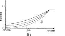
图8是用于响应于燃料中的酒精浓度在奥托循环运行和阿特金森循环运行之间进行变换的示例变换廓线。8 is an example transition profile for transitioning between Otto cycle operation and Atkinson cycle operation in response to alcohol concentration in fuel.
具体实施方式Detailed ways
参考图1,示出由电子发动机控制器12控制的包括多个汽缸的发动机,其中一个汽缸由图1示出。发动机10包括燃烧室30和汽缸壁32,活塞36位于其中并连接到曲轴40。燃烧室30如图所示经由相应的进气门52及排气门54与进气歧管44和排气歧管48连通。凸轮相位驱动器25如图所示连接到凸轮轴130。机油存储罐161向泵160供给机油。基于来自发动机控制器12的命令,该泵将加压的机油经由阀170供给给凸轮相位驱动器25。凸轮轴130配备有至少两个进气凸轮凸角廓线和至少一个排气凸轮凸角廓线。进气凸轮凸角廓线可以具有不同的升程量、不同的持续时间,并可以在相位上不同(即,凸轮凸角可以在尺寸上和方向上相对于彼此发生改变)。或者,该系统可以使用分离的进气凸轮和排气凸轮。凸轮位置传感器150向控制器12提供凸轮位置信息。进气凸轮凸角廓线包括低升程廓线和高升程廓线。进气门摇臂56和排气门摇臂57将来自凸轮轴的气门开启力传输到相应的气门杆。进气门摇臂56包括用于选择性地在低升程凸轮凸角廓线和高升程凸轮凸角廓线之间进行变换的空动构件。液压驱动的销(未示出)选择性地将摇臂连接到一起,以基于来自控制器12的控制信号启用或停用高升程凸轮廓线。或者,可以使用不同的气门机构驱动器和设计来代替所示的设计(如,可以使用推杆而不是顶置凸轮、可以使用电子机械气门机构而不是液压机械气门机构)。Referring to FIG. 1 , an engine including a plurality of cylinders, one of which is shown in FIG. 1 , is shown controlled by an
进气歧管44如图所示具有与其连接的燃料喷射器66,燃料喷射器66用于根据来自控制器12的信号脉冲宽度成比例地供给液体燃料。通过包括燃料箱、燃料泵及燃料导管(未示出)的燃料系统(未示出)向燃料喷射器66供给燃料。或者,可以配置发动机,以将燃料直接喷射到发动机汽缸中,即本领域技术人员所知的直接喷射。此外,可以将燃料直接喷射到汽缸和进气道中。此外,可以将不同类型的燃料喷射到汽缸和进气道中。另外,进气歧管44如图所示与可选的电子节气门62连通。
无分电器点火系统88响应于控制器12经由火花塞92向燃烧室30提供点火火花。通用排气氧(UEGO)传感器76如图所示连接到催化转化器70上游的排气歧管48。或者,可以用双态排气氧传感器替换UEGO传感器76。双态排气氧传感器98如图所示连接到催化转化器70下游的排气管78。或者,传感器98也可以是UEGO传感器。催化转化器温度可以由温度传感器77测量,和/或基于如发动机转速、负荷、空气温度、发动机温度,和/或空气流量,或其组合这样的工况估计。
在一个示例中,催化转化器70可以包括多个催化剂块。在另一个示例中,可以使用多个排放控制装置,而其中每个都具有多个催化剂块。在一个示例中,催化转化器70可以是三元催化剂。In one example, catalytic converter 70 may include a plurality of catalyst bricks. In another example, multiple emission control devices, each with multiple catalyst bricks, may be used. In one example, catalytic converter 70 may be a three-way catalyst.
控制器12如图1所示是常规的微计算机,其中包括微处理器单元102、输入/输出端口104、只读存储器106、随机存取存储器108、保活存储器110及常规的数据总线。除上述信号外,控制器12如图所示还接收来自连接到发动机10的传感器的各种信号,包括:来自连接到冷却套管114的温度传感器112的发动机冷却剂温度(ECT)、来自连接到加速器踏板的踏板位置传感器119的踏板位置、来自传感器190的向凸轮相位驱动器25供给的机油的压力测量值、来自连接到进气歧管44的压力传感器122的发动机歧管压力(MAP)的测量值、来自发动机爆震传感器的爆震信号(未示出)、来自燃料类型传感器的燃料类型(未示出)、来自湿度传感器38的湿度、来自温度传感器117的发动机进气温度或歧管温度的测量值(ACT),及来自检测曲轴40的位置的霍尔效应传感器118的发动机位置。在本发明的一个优选方面,发动机位置传感器118在曲轴的每次旋转中产生预定数量的等距脉冲,通过该脉冲可以确定发动机转速(RPM)。
现参考图2A,示出用奥托循环运行的发动机的名义气门重叠和气门正时的示例图。该图示出示例高升程气门廓线,其中增加进气门开启持续时间以改进发动机呼吸。排气门开启正时由外环21表示。进气门开启正时由内环22表示。气门正时以上止点(TDC)和下止点(BDC)汽缸位置为参照。注意,从进气门开启(IVO)到排气门关闭(EVC)的气门重叠期近似地以TDC为中心。进气门关闭(IVC)和排气门开启(EVO)近似地以BDC为中心。具体来说,IVO设置为上止点之前15°,IVC设置为下止点之后53°,EVO设置为下止点之前50°,而EVC设置为上止点之后19°。可以设置这些气门正时,以在整个发动机运行范围中提供发动机性能、排放及燃料经济性之间的折中。Referring now to FIG. 2A , an example graph of nominal valve overlap and valve timing for an engine operating on the Otto cycle is shown. The figure shows an example high-lift valve profile where intake valve opening duration is increased to improve engine breathing. Exhaust valve opening timing is indicated by
注意,也可以取决于控制目标提前或延迟图2A所示的正时。此外,凸轮凸角升程持续时间也可以和图2A所示不同,而凸角的升程部分的开始和结束位置也可以相对于凸轮凸角改变。另外,可以响应于发动机工况单独或同时调节进气门和排气门相位正时(即,相对于特定曲轴位置的气门开启和关闭时间)。Note that the timing shown in FIG. 2A may also be advanced or delayed depending on the control target. In addition, the cam lobe lift duration can also vary from that shown in Figure 2A, and the start and end positions of the lobe's lift portion can also vary relative to the cam lobe. Additionally, intake and exhaust valve phasing timing (ie, valve opening and closing times relative to a particular crankshaft position) may be adjusted individually or simultaneously in response to engine operating conditions.
参考图2B,示出用阿特金森循环运行的发动机的延迟或较晚的发动机进气门正时的示例图。在一个示例中,排气门正时固定,而通过例如在凸轮凸角廓线之间进行变换来调节进气门正时。在该示例中,IVO和EVC近似以进气行程的上止点为中心。通过延长进气凸轮凸角的持续时间,将IVC从奥托循环正时示例延迟到83°。延迟IVC位置可以允许在压缩行程的第一部分期间将部分汽缸进气排出到进气歧管中,从而减小汽缸的有效压缩比(注:有效压缩比指进气门关闭时的燃烧室容积相对于气门关闭的上止点的燃烧室容积之比,而几何压缩比指下止点的燃烧室容积相对于上止点的燃烧室容积之比)。IVO设置为上止点之前15°,EVO设置为下止点之前50°,而EVC设置为上止点之后19°。在可选配置中,可以变换凸轮廓线,而且还可以相对于给定的曲轴位置调节进气相位。这样的组合允许通过延迟进气凸轮来进一步减小有效压缩比。Referring to FIG. 2B , an example graph of retarded or later engine intake valve timing for an engine operating on the Atkinson cycle is shown. In one example, exhaust valve timing is fixed while intake valve timing is adjusted by, for example, shifting between cam lobe profiles. In this example, IVO and EVC are approximately centered on top dead center of the intake stroke. Retards IVC from the Otto cycle timing example to 83° by extending the duration of the intake cam lobe. Retarding the IVC position can allow some of the cylinder's charge to be expelled into the intake manifold during the first part of the compression stroke, thereby reducing the cylinder's effective compression ratio (Note: The effective compression ratio refers to the combustion chamber volume when the intake valve is closed relative to The ratio of the combustion chamber volume at the top dead center when the valve is closed, and the geometric compression ratio refers to the ratio of the combustion chamber volume at the bottom dead center to the combustion chamber volume at the top dead center). IVO is set at 15° before top dead center, EVO is set at 50° before bottom dead center, and EVC is set at 19° after top dead center. In an optional configuration, the cam profile can be shifted and the intake phasing can also be adjusted relative to a given crankshaft position. This combination allows the effective compression ratio to be further reduced by retarding the intake cam.
另一方面,延迟气门正时的益处在某些工况期间会受到限制。例如,对于具有单一进气凸轮廓线的发动机,廓线通常是低发动机转速下的怠速稳定性和燃料消耗与高转速和高负荷下的发动机性能之间的折中。在延迟固定升程凸轮以改进部分负荷的发动机运行时,凸轮延迟的量会受到燃烧稳定性的限制。即,如果凸轮延迟超出特定的量,则随着汽缸工况使燃烧特性(如,温度、压力、空燃混合及燃烧速率)发生改变,发动机排放、发动机噪声及发动机振动会劣化。通过对不同的工况提供不同的气门升程廓线,可以增加部分负荷的发动机工况期间的凸轮延迟量。低升程凸轮廓线可以在低发动机转速下改进燃烧稳定性并减少发动机排放,因为汽缸空气-燃料进气可以更好地混合并更加均匀地燃烧。此外,即使排气门凸角和进气门凸角由同一凸轮轴驱动,低升程凸轮廓线也可以提供减少进气门和排气门之间的有效重叠的方法。On the other hand, the benefits of retarding valve timing may be limited during certain operating conditions. For example, for an engine with a single intake cam profile, the profile is generally a compromise between idle stability and fuel consumption at low engine speeds and engine performance at high speeds and loads. When retarding fixed lift cams to improve part load engine operation, the amount of cam retardation may be limited by combustion stability. That is, if the cam retard exceeds a certain amount, engine emissions, engine noise, and engine vibration may be degraded as cylinder operating conditions change combustion characteristics (eg, temperature, pressure, air-fuel mixture, and combustion rate). The amount of cam retard during part load engine operating conditions may be increased by providing different valve lift profiles for different operating conditions. The low-lift cam profile improves combustion stability at low engine speeds and reduces engine emissions because the cylinder air-fuel charge is better mixed and burns more evenly. Furthermore, even though the exhaust and intake valve lobes are driven by the same camshaft, the low-lift cam profile may provide a means of effectively reducing the overlap between the intake and exhaust valves.
在另一个示例中,可以对进气门和/或排气门(双独立凸轮正时)单独调节气门升程和/或气门正时来实现所示的正时。该类系统允许进气门和排气门正时延迟,同时气门重叠可以设置为正(即,进气门和排气门同时开启)或设置为负(即,气门之间没有重叠)。In another example, valve lift and/or valve timing may be individually adjusted for the intake and/or exhaust valves (dual independent cam timing) to achieve the timings shown. This type of system allows intake and exhaust valve timing to be retarded, while valve overlap can be set to be positive (ie, the intake and exhaust valves open simultaneously) or negative (ie, there is no overlap between the valves).
参考图2B,排气门开启正时由外环23表示。进气门开启正时由内环24表示。如上所述,气门正时以上止点(TDC)和下止点(BDC)汽缸位置为参照。从进气门开启(IVO)到排气门关闭(EVC)的气门重叠期近似以TDC为中心。进气门关闭(IVC)和排气门开启(EVO)的中心在BDC后,近似在下止点后(ABDC)17°处。Referring to FIG. 2B , exhaust valve opening timing is represented by
图2A和2B所示的气门正时是进气门和排气门正时的示例。相应地,可以在整个发动机运行范围中提供性能和燃料经济性之间的折中的其他进气门和排气门正时也是可能的。例如,延迟的进气门关闭位置可以出现在典型汽缸进气行程的BDC之后30°到BDC之后100°以上的范围内。具体来说,可以设置气门正时,使得可以实现在8.5∶1和14.5∶1之间的有效压缩比范围。当然,本发明的不同实施例可以缩小或拓宽有效压缩比的范围(如,一个示例可以允许在9∶1和15∶1之间调节有效压缩比,而另一个示例可以允许8∶1和12.5∶1之间的调节范围)。此外,可以设置气门正时,以实现所提到的那些范围之间的任何压缩比范围。The valve timings shown in FIGS. 2A and 2B are examples of intake and exhaust valve timings. Accordingly, other intake and exhaust valve timings are possible that may provide a compromise between performance and fuel economy throughout the engine operating range. For example, the retarded intake valve closing position may occur within a range of 30° after BDC to more than 100° after BDC for a typical cylinder intake stroke. Specifically, valve timing may be set such that an effective compression ratio range between 8.5:1 and 14.5:1 may be achieved. Of course, different embodiments of the invention may narrow or widen the range of effective compression ratios (e.g., one example may allow adjustment of the effective compression ratio between 9:1 and 15:1, while another example may allow 8:1 and 12.5 : Adjustment range between 1). Furthermore, the valve timing can be set to achieve any range of compression ratios between those mentioned.
虽然延迟的进气门关闭位置可以出现在BDC之后30°到BDC之后100°以上的范围内,但上述进气门和排气门正时角度之间的中间角度也是可能的。进气开启和排气门关闭位置的组合及子组合可用于实现期望的排放、燃料经济性和/或性能水平。因此,附图并不限制本发明的外延或范围。Intermediate angles between the intake and exhaust valve timing angles described above are also possible, although the retarded intake valve closing position may occur in the range of 30° after BDC to over 100° after BDC. Combinations and subcombinations of intake open and exhaust valve closed positions may be used to achieve desired emissions, fuel economy, and/or performance levels. Accordingly, the drawings do not limit the extension or scope of the invention.
现参考图2C,示出两个凸轮凸角廓线的示例的截面示意图。标号2 5表示示例凸轮的基圆。在摇臂停在基圆上时,进气门保持关闭。标记26表示低升程凸轮凸角,其持续时间比高升程凸轮凸角27长。在摇臂随低升程廓线运动时,气门升程减小而气门开启持续时间增加。在摇臂随高升程廓线运动时,气门升程增加而气门开启持续时间减少。Referring now to FIG. 2C , a schematic cross-sectional view of two examples of cam lobe profiles is shown.
还应注意,电动气门也可以按图2A和2B所示的正时运行。另外,可以使用不同的气门或不同的升程控制策略来改变电动气门的升程,以实现类似于所示的控制。It should also be noted that the electric valve can also operate with the timing shown in Figures 2A and 2B. In addition, different valves or different lift control strategies can be used to change the lift of the electric valve to achieve control similar to that shown.
现参考图3,示出多燃料发动机的发动机起动序列的示例流程图。在步骤301,例程确定是否存在起动发动机的请求。起动请求可以由操作者做出或部分地由自动系统,例如混合动力汽车控制器做出。如果已做出起动请求,则例程进入步骤303。否则,例程退出。Referring now to FIG. 3 , an example flow diagram of an engine start sequence for a multi-fuel engine is shown. In
在步骤303,从存储器中调出发动机最后一次燃烧的燃料的燃料特性(如,燃料中的酒精浓度、燃料挥发性、燃料蒸汽压力,和/或辛烷值)。燃料特性可以从测量燃料特性的传感器中检索得到,和/或通过测量可用于确定燃料特性的其他发动机运行特性的传感器推断得到。例如,美国专利6,588,253提供一种确定燃料中的酒精含量的方法,将其完整包括在此作为参考,而美国专利5,467,755提供一种确定不同的酒精燃料浓度对发动机空燃比控制的影响的方法及一种用于补偿这样的影响的方法,也将其完整包括在此作为参考。在起动发动机之前,从存储器中检索出反映停止发动机之前燃烧的燃料特性的参数。然后例程进入步骤305。At
在步骤305,通过可用的传感器信息确定当前燃料特性。在发动机起动之前,或起动后较短时间内,可以查询燃料传感器,以便可以确定将向发动机供给的燃料的类型。可以使用不同类型的传感器来确定燃料特性。这些传感器可以基于光学特性或电气特性(如,电容或波长传递率(wavelength transmissibility))运行,因此并不限制本发明的范围或外延。此外,在某些实施例中,如果需要的话,可以略去燃料类型传感器。然后例程进入步骤307。At
在步骤307,起动发动机。来自步骤305和303的燃料特性用于准备发动机起动。如果步骤305和303指示基本上相同的燃料特性,则响应于燃料特性设置燃料喷射正时、气门廓线、气门相位,及点火正时。例如,对给定的环境空气压力、环境空气温度,及发动机温度,通过查询包含根据经验确定的产生期望的起动特性的燃料量的表来确定燃料量。以类似的方式确定点火正时、凸轮廓线及凸轮定相设置,然而,使用加压的发动机机油索引的凸轮正时装置可以由锁定机制固定或保持在原位,直至得到发动机机油压力。通常,将基础气门升程设置为低廓线,并延迟凸轮相位,以使有效的发动机压缩比低于发动机可实现的最高压缩比。例如,对14∶1几何压缩比的发动机,可以在阿特金森循环模式中设置气门正时和气门升程,以使有效压缩比为12.5∶1或更低。通过减小起动压缩比,在起动期间可以使用较小的起动机来转动发动机。另外,如果发动机在较热并加注低辛烷值燃料时重起动,则减小有效压缩比可以减少发动机爆震。减小起动期间的压缩比还可以减少起动排放,因为有较少的燃料被推入活塞和汽缸壁之间,还因为将一部分汽缸内容物推回进气歧管中也可以缩短发动机暖机时间并改进燃料蒸发。在做出发动机停止请求时,可以设置基础凸轮廓线和凸轮相位,以使气门在发动机进行后续的起动时处于“待命”状态。In
在另一个实施例中,能够在发动机停止时调节气门正时的系统(如,电动气门)可以在发动机起动之前和/或起动期间调节气门运行。在一个示例中,可以将酒精浓度用于索引定义起动期间的气门正时的函数或表。可以在阿特金森循环中确定气门正时,以便响应于发动机燃料中的酒精浓度限制压缩比。换句话说,酒精浓度可用于调节进气门正时延迟,以便响应于酒精浓度控制推回进气歧管的汽缸内容物的量。气门正时可以根据经验确定并存储在使用例如发动机转速和发动机负荷索引的表中。In another embodiment, a system capable of adjusting valve timing while the engine is stopped (eg, electric valves) may adjust valve operation prior to and/or during engine start. In one example, alcohol concentration may be used to index a function or table that defines valve timing during cranking. Valve timing may be determined in the Atkinson cycle to limit the compression ratio in response to the alcohol concentration in the engine fuel. In other words, alcohol concentration may be used to adjust intake valve timing retard to control the amount of cylinder contents pushed back into the intake manifold in response to alcohol concentration. Valve timing may be determined empirically and stored in a table indexed using, for example, engine speed and engine load.
在设置预先确定的点火正时、气门正时、气门升程及燃料量之后起动发动机。然后例程进入步骤309。The engine is started after setting predetermined ignition timing, valve timing, valve lift and fuel quantity. The routine then goes to step 309.
在步骤309,响应于发动机工况设置气门正时和点火正时。在一个实施例中,随着发动机旋转并达到怠速,发动机机油泵160产生压力。在机油压力达到预先确定的水平时,可以根据例如燃料中的酒精浓度、发动机工况及操作者扭矩需求来改变凸轮相位和凸轮升程量。在一个示例中,使用发动机转速、负荷及燃料特性来索引根据经验确定的表或函数,可确定凸轮升程和凸轮相位。然后例程进入步骤311。In
在步骤311,系统转换到使用发动机传感器反馈来控制发动机点火、气门正时、气门升程及燃料量的控制模式。该模式由图5的方法描述。然后例程退出。At
现参考图4,示出可以用多种燃料运行的汽缸的停止序列的示例流程图。在步骤401,例程确定是否存在停止发动机的请求。发动机停止请求可以由操作者做出,或通过另一种手段,如另一控制系统(如,混合动力系统控制器)做出。如果存在停止发动机的请求,则例程进入步骤403。否则,例程退出。Referring now to FIG. 4 , an example flow diagram of a deactivation sequence for cylinders that may operate on multiple fuels is shown. In
在步骤403,将凸轮相位和凸轮廓线设置到基位置。将凸轮廓线设置到具有较长持续时间的低升程位置。该廓线使得有可能延迟进气门关闭时间,以便将汽缸内容物中的至少部分推回进气歧管,从而减小该汽缸的有效压缩比。At
可以将凸轮相位设置到部分取决于起动时的期望压缩比及凸轮凸角廓线的位置。例如,低升程凸轮廓线可以设计为考虑到各种因素,如期望的压缩比高限、期望的压缩比低限,及凸轮相位调节装置的范围。因此,在运行目标改变时,可以改变进气门开启持续时间。因此,将基凸轮相位设置到允许发动机以小于几何压缩比的有效压缩比起动的位置。通常,该有效压缩比设置为低于12.5∶1,从而即使发动机以较暖的温度起动,发动机也可以在产生爆震的可能性较低的情况下重起动。然后例程进入步骤405。The cam phase can be set to a position that depends in part on the desired compression ratio and cam lobe profile at start-up. For example, a low-lift cam profile may be designed to take into account various factors such as a desired high compression ratio limit, a desired low compression ratio limit, and range of cam phasing. Therefore, when the operation target changes, the intake valve opening duration can be changed. Therefore, the base cam phase is set to a position that allows the engine to start at an effective compression ratio that is less than the geometric compression ratio. Typically, the effective compression ratio is set lower than 12.5:1 so that the engine can be restarted with less likelihood of knocking even if the engine is started at a warmer temperature. The routine then goes to step 405 .
在步骤405,将当前燃料特性保存到存储器中。燃料特性和/或参数可以通过上述方法或通过其他已知方法确定,并在接收到发动机停止请求时保存。然后例程退出。At
现参考图5,示出使用多种燃料运行发动机的示例策略的流程图。在步骤501,确定发动机工况。发动机工况可以包括但不限于操作者扭矩需求、发动机温度、大气压力、环境空气温度,及燃料特性。然后例程进入步骤503。Referring now to FIG. 5 , a flowchart of an example strategy for operating an engine using multiple fuels is shown. In
在步骤503,例程响应于燃料特性确定期望的压缩比。然后可以将期望的压缩比用于确定初始汽缸循环运行模式和气门正时。In
在第一实施例中,例程使用逻辑来确定发动机在用奥托循环还是阿特金森循环运行。即,评估各种发动机工况,以确定期望的汽缸运行状态。例程可以响应于若干运行参数,包括发动机爆震传感器的信号、期望的扭矩,及燃料特性来选择汽缸循环。这些工况可以测量或推断得到。该结构允许系统用包含一定范围的燃料混合物的单个燃料箱运行,或用包含不同燃料的多个燃料箱运行。In a first embodiment, a routine uses logic to determine whether the engine is running on an Otto cycle or an Atkinson cycle. That is, various engine operating conditions are evaluated to determine desired cylinder operating states. The routine may select a cylinder cycle in response to several operating parameters, including signals from an engine knock sensor, desired torque, and fuel characteristics. These conditions can be measured or inferred. This configuration allows the system to operate with a single fuel tank containing a range of fuel mixtures, or with multiple fuel tanks containing different fuels.
在可选实施例中,在喷射来自不同喷射器的不同类型燃料的系统中,汽缸循环模式可以简单地基于所喷射的燃料的类型(如,喷射来自不同来源,如高辛烷值燃料喷射器和低辛烷值燃料喷射器的燃料的系统)。通过得知所喷射的燃料类型,例程可以简单地选择适用于所喷射的燃料类型的汽缸模式。例如,如果将高辛烷值燃料直接喷射到汽缸中,则例程可以选择14∶1压缩比的奥托循环。如果系统后来变换到低辛烷值燃料,则汽缸循环模式可以转换到例如9∶1压缩比的阿特金森循环。另外,如果燃料类型由高辛烷值燃料改变为低辛烷值燃料,则喷射到汽缸中的低辛烷值燃料的量可以少于转换之前喷射的高辛烷值燃料的量。因为低辛烷值燃料具有比高辛烷值燃料高的能量密度,所以低辛烷值燃料量减少。因此,随着燃料中的低辛烷值燃料浓度增加,为产生给定量的扭矩而喷射的燃料量减少。In an alternative embodiment, in systems injecting different types of fuel from different injectors, the cylinder cycle pattern may simply be based on the type of fuel injected (eg, injection from a different source, such as a high-octane fuel injector and low-octane fuel injector fuel systems). Knowing the type of fuel being injected, the routine can simply select the cylinder mode appropriate for the type of fuel being injected. For example, if high octane fuel is injected directly into the cylinder, the routine may select the Otto cycle with a 14:1 compression ratio. If the system is later switched to low octane fuel, the cylinder cycle mode can be switched to, for example, an Atkinson cycle with a 9:1 compression ratio. Additionally, if the fuel type is changed from high octane fuel to low octane fuel, the amount of low octane fuel injected into the cylinder may be less than the amount of high octane fuel injected before the switch. Because low-octane fuel has a higher energy density than high-octane fuel, the amount of low-octane fuel is reduced. Thus, as the concentration of low octane fuel in the fuel increases, the amount of fuel injected to produce a given amount of torque decreases.
在上述第一实施例中,通过使用上述方法中的一种或使用另一种已知方法,例程可以使用传感器信息来确定或推断燃料类型和/或燃料特性。燃料类型和/或燃料特性可用于索引包含根据经验确定的发动机数据的表或函数,其中的发动机数据描述不同燃料的期望的有效压缩比。如果正在向发动机供给的燃料未由该表或函数具体描述,则可以对该表或函数进行插值,以确定出发动机的有效压缩比。做出列表输入,以便将不产生发动机爆震或只产生微量的发动机爆震的最高压缩比输入到该表中。然后,响应于期望的有效压缩比选择奥托循环模式或阿特金森循环模式和气门正时。通常,有效压缩比在阿特金森循环模式中可以改变更多,因为对较晚的进气门关闭时间存在较大范围的控制。具体来说,可以响应于燃料特性从进气行程的下止点延迟进气门正时,以减小汽缸的有效压缩比。例如,如果由低辛烷值燃料和高辛烷值燃料组成的混合燃料中的低辛烷值燃料浓度增加,则可以延迟进气门正时,以减小汽缸的有效压缩比。在燃料辛烷值发生改变时,这可以减少发动机的爆震倾向。另一方面,如果混合燃料中的酒精浓度增加,则可以提前进气门正时。In the first embodiment described above, the routine may use sensor information to determine or infer fuel type and/or fuel characteristics using one of the methods described above or using another known method. The fuel type and/or fuel characteristics may be used to index a table or function containing empirically determined engine data describing the expected effective compression ratios for different fuels. If the fuel being supplied to the engine is not specifically described by the table or function, the table or function can be interpolated to determine the engine's effective compression ratio. A tabular entry is made so that the highest compression ratio that produces no or only a slight amount of engine knock is entered into the table. Otto cycle mode or Atkinson cycle mode and valve timing are then selected responsive to the desired effective compression ratio. In general, the effective compression ratio can vary more in Atkinson cycle mode because there is a greater range of control over later intake valve closing times. Specifically, intake valve timing may be retarded from bottom dead center of the intake stroke in response to fuel characteristics to decrease the effective compression ratio of the cylinder. For example, if the concentration of low-octane fuel in a fuel blend consisting of low-octane fuel and high-octane fuel is increased, intake valve timing may be retarded to decrease the cylinder's effective compression ratio. This reduces the engine's propensity to knock when fuel octane changes are made. On the other hand, if the alcohol concentration in the fuel mixture increases, the intake valve timing can be advanced.
在该步骤中也可以调节点火角正时。如果燃料混合物中的酒精浓度增加,则可以提前点火正时,因为在燃料酒精浓度增加时,该燃料能减少造成发动机爆震的倾向。相反,在燃料混合物中的低辛烷值燃料浓度增加时,可以延迟点火角正时。通过在低辛烷值燃料或高辛烷值燃料的浓度改变时只是增加或减小来自基点火命令的角度,可以按此方式调节点火正时。该方法可以改进所燃烧的燃料的能量利用率。The ignition angle timing can also be adjusted in this step. If the alcohol concentration in the fuel mixture is increased, the ignition timing can be advanced because the fuel has a reduced propensity to cause engine knock when the alcohol concentration of the fuel is increased. Conversely, the ignition angle timing may be retarded as the concentration of low octane fuel in the fuel mixture increases. Ignition timing can be adjusted in this manner by simply increasing or decreasing the angle from the base spark command as the concentration of low octane fuel or high octane fuel changes. This approach can improve the energy utilization of the fuel being burned.
再此外,在该步骤可以调节排气门的正时。在特定的工况下,可能希望响应于燃料特性和/或汽缸循环模式提前或延迟排气门正时。例如,如果混合燃料中的低辛烷值燃料浓度增加且发动机用阿特金森循环模式运行,则希望延迟排气门开启,以在开启排气门之前向活塞传输较多汽缸压力能量。可调节的排气门正时可提供本发明的另一个自由度。然后例程进入步骤505。Still further, the timing of the exhaust valves may be adjusted at this step. Under certain operating conditions, it may be desirable to advance or retard exhaust valve timing in response to fuel characteristics and/or cylinder cycle mode. For example, if the concentration of low octane fuel in the blend is increased and the engine is operating in Atkinson cycle mode, it may be desirable to delay exhaust valve opening to deliver more cylinder pressure energy to the piston prior to opening the exhaust valve. Adjustable exhaust valve timing may provide another degree of freedom for the present invention. The routine then goes to step 505.
在步骤505,例程确定阿特金森汽缸循环是否是具体期望的。在特定的情况下,可能在发动机可能以高压缩比运行时希望发动机用阿特金森循环运行。例如,混合动力汽车可以按基本上恒定的发动机转速和负荷来运行发动机,以对蓄电池充电和/或向车轮供给发动机扭矩的一部分。因此,即使可能用高压缩比奥托循环模式运行发动机,使用低辛烷值燃料、高辛烷值燃料,或低辛烷值燃料和高辛烷值燃料的可变混合物组成的燃料的发动机也可以用阿特金森循环模式运行。此外,如果发动机进入特定的转速/负荷范围,也可以请求使用阿特金森循环模式。在阿特金森模式中,气门升程减小而气门开启时间增加,以使燃烧稳定性得到改进。因此,即使发动机用单种燃料运行,也可能在奥托循环和阿特金森循环之间变换。如果已请求了阿特金森模式,则例程进入步骤509。否则,例程进入步骤507。In
在步骤509,期望的汽缸循环模式变换为阿特金森模式。如果响应于特定发动机工况或响应于外部系统的请求,请求了阿特金森循环,则用阿特金森模式和通过使用具有类似特性的燃料进行的经验测试预先确定的压缩比来运行汽缸。具体来说,使用燃料特性来索引输出气门正时的表,且例程进入步骤507。In
在步骤507,例程确定期望的扭矩在当前选择的期望汽缸循环模式中是否可用。例程使用发动机转速和燃料特性来索引包含根据经验确定的发动机最大扭矩的表。将发动机最大扭矩应用于用期望的汽缸循环模式运行、使用具有类似特性的燃料,并在当前发动机转速下的发动机。期望的扭矩可以由操作者命令请求或由例如混合动力控制器这样的外部系统请求。如果发动机能够产生期望的发动机扭矩,则例程进入步骤511。否则,例程进入步骤525。In
在步骤511,发动机确定发动机是否在当前的工况下发生爆震。如果发动机发生爆震且如果发动机扭矩请求稳定或在增加,则例程进入步骤513。否则,例程进入步骤515。In
在步骤513,做出调节以减少发动机爆震。如果发动机在选择的凸轮相位和点火提前条件下在奥托循环模式中发生爆震,则可以延迟点火角,以尝试减少发动机爆震。但是,如果发动机在延迟点火后继续爆震,则可以在估计的发动机效率减小达预先确定的量之后选择阿特金森循环。In
如发动机在选择的凸轮相位和点火提前条件下在阿特金森循环模式中发生爆震,则可以进一步延迟点火以控制发动机爆震。If the engine knocks in the Atkinson cycle mode under selected cam phasing and spark advance conditions, the spark can be further retarded to control engine knock.
在一个示例中,在汽缸用奥托循环模式运行并发生发动机爆震时,初始延迟点火。如果发动机继续爆震,则可以将汽缸变换到阿特金森循环模式,其中汽缸的有效压缩比减小。如果发动机继续爆震,则可以做出进一步的压缩比调节和点火调节。然后例程进入步骤515。In one example, spark is initially retarded when cylinders are operating in Otto cycle mode and engine knock occurs. If the engine continues to knock, the cylinders may be shifted into an Atkinson cycle mode where the effective compression ratio of the cylinders is reduced. If the engine continues to knock, further compression ratio adjustments and spark adjustments may be made. The routine then proceeds to step 515.
在步骤515,例程调节凸轮提前和延迟限制以及点火提前和延迟限制。由于该发动机能够在一定的燃料混合物范围之间(如,在100%的汽油和100%的酒精之间)运行,本发明的方法可以根据当前的燃料类型和/或燃料特性调节凸轮正时和点火限制。例如,如果基于汽油的燃料中的酒精含量增加10%,则阿特金森循环模式的气门正时提前可以增加5°,从而增加发动机的有效压缩比。换句话说,由于最近吸入的酒精降低了燃料造成发动机爆震的敏感性,可以增加发动机压缩比,以改进发动机输出。还可以调节发动机点火提前限制,以适应燃料类型和/或燃料特性的改变。因此,允许凸轮相位延迟和提前限制以及点火提前在燃料类型和/或燃料特性改变时改变。具体的凸轮正时和气门升程量可以根据经验确定,并可以由例如发动机转速和发动机负荷索引。In
另外,可以响应于由汽缸燃烧的燃料的类型,限制节气门开启量或节流板位置。该控制动作还可以用作限制吸入汽缸的空气量的方法。通过限制汽缸空气进气,控制发动机爆震所需的点火延迟量也会减少。然后例程进入步骤517。Additionally, throttle opening amount or throttle plate position may be limited in response to the type of fuel being combusted by the cylinder. This control action can also be used as a means of limiting the amount of air drawn into the cylinders. By restricting cylinder air intake, the amount of spark retard required to control engine knock is also reduced. The routine then proceeds to step 517.
在步骤517,例程确定期望的汽缸循环模式是否已改变。如果是,则例程进入步骤519。如果否,则例程进入步骤521。In
在步骤519,调节凸轮、节流板角度,及点火来改变循环模式并减少发动机扭矩扰动。In
在期望的汽缸循环从阿特金森循环改变为奥托循环时,可以延迟凸轮正时并增加点火提前角。可以延迟凸轮,以在允许较少空气流入汽缸的凸轮位置上将凸轮廓线变换到高升程廓线。该动作有助于减少发生气门升程转换之前和之后的汽缸空气量差异。另外,可以在转换期间减少节气门开启,以进一步限制转换期间的发动机扭矩。在调节凸轮位置时,可以提前点火角,从而增加发动机扭矩并缓解延迟凸轮正时的效应。通过新吸入的燃料增加的辛烷值,有可能做出附加的点火提前。可以在调节凸轮相位期间或之后变换凸轮廓线,但转换通常在已改变凸轮相位之后做出,以使扭矩扰动的可能性降低。在凸轮廓线改变期间,也可以通过延迟点火角、滑动变速器扭矩变换器离合器,及关闭节气门开启来控制发动机扭矩。可以在凸轮廓线变换之后调节凸轮相位、节气门开启量,及点火。作为示例,请参见图6。Cam timing may be retarded and spark advance may be increased as the desired cylinder cycle changes from the Atkinson cycle to the Otto cycle. The cam may be retarded to shift the cam profile to a high-lift profile at a cam position that allows less air to flow into the cylinder. This action helps reduce the difference in cylinder air volume before and after a valve lift transition occurs. Additionally, throttle opening may be reduced during transitions to further limit engine torque during transitions. When the cam position is adjusted, the ignition angle can be advanced, which increases engine torque and mitigates the effects of retarded cam timing. It is possible to make additional spark advance through the increased octane of the freshly inhaled fuel. The cam profile can be shifted during or after adjusting the cam phasing, but the shifting is usually made after the cam phasing has been changed so that the likelihood of torque disturbances is reduced. Engine torque may also be controlled by retarding the spark angle, slipping the transmission torque converter clutch, and closing the throttle opening during cam profile changes. Cam phasing, throttle opening, and spark can be adjusted after a cam profile change. See Figure 6 for an example.
在从奥托循环转换到阿特金森循环时,也可以改变节流板位置、凸轮相位、凸轮升程、点火提前,及扭矩变换器离合器滑动量。为了开始转换,可以增加点火延迟并提前凸轮相位。通过提前凸轮相位,可以增加吸入汽缸中的空气的量,以使凸轮廓线变换时进入汽缸的空气的质量不大幅减小。可以响应于燃料特性的改变延迟点火角,从而允许该系统抵消因提前凸轮造成的汽缸空气量增加的至少部分。可以延迟点火以抵消凸轮相位的改变。在凸轮廓线或凸轮升程量转换期间,在气门升程量减小时,可以增加点火提前并增加节气门开启。可以使用这些调节来限制改变气门正时和气门升程可能造成的扭矩扰动。Throttle plate position, cam phasing, cam lift, spark advance, and torque converter clutch slip can also be changed when transitioning from the Otto cycle to the Atkinson cycle. To start the transition, the ignition retard can be increased and the cam phase advanced. By advancing the cam phase, the amount of air drawn into the cylinder can be increased so that the mass of air entering the cylinder does not decrease significantly when the cam profile changes. The ignition angle may be retarded in response to changes in fuel properties, allowing the system to counteract at least a portion of the increase in cylinder air mass due to advancing the cam. The spark can be retarded to counteract changes in cam phasing. During cam profile or cam lift transitions, spark advance may be increased and throttle opening may be increased as valve lift decreases. These adjustments may be used to limit torque disturbances that may be caused by changing valve timing and valve lift.
在该步骤中也可以在汽缸循环模式改变时改变燃料正时。在一个实施例中,在将燃料直接喷射到汽缸中时,可以在汽缸循环模式改变时改变喷射期的开始或结束。此外,也可以在汽缸循环模式改变时改变汽缸循环期间的喷射次数。例如,在发动机燃烧具有高酒精浓度的燃料时,燃料喷射可以在进气门开启时开始,并在进气门关闭后继续。然而,如果发动机用阿特金森模式运行并燃烧具有高浓度的低辛烷值燃料的燃料,则燃料的第一喷射可以在进气门开启之后的一段时间开始。第一喷射可以在规定的时间之后停止。而第二喷射可以在指定的另一段时间之后开始。然后例程进入步骤521。Fuel timing may also be changed in this step when the cylinder cycle mode changes. In one embodiment, when injecting fuel directly into a cylinder, the start or end of the injection period may be changed when the cylinder cycle pattern changes. Additionally, the number of injections during a cylinder cycle may also be changed when the cylinder cycle pattern is changed. For example, in an engine burning fuel with a high alcohol concentration, fuel injection may begin when the intake valve opens and continue after the intake valve closes. However, if the engine is operating in Atkinson mode and burning fuel with a high concentration of low octane fuel, the first injection of fuel may begin some time after the intake valve opens. The first injection may be stopped after a specified time. And the second injection can start after another specified period of time. The routine then goes to step 521.
在步骤521,可以响应于操作者或控制器命令调节凸轮相位、排气门正时、节气门开启量及点火角。通常,使用步骤503、505和513中确定的气门正时来保持期望的压缩比。然而,也可以在发动机负荷改变时改变有效压缩比。例如,如果在步骤503中使用燃料特性确定期望的压缩比为13∶1,则如果需要的话,步骤521可以在发动机负荷较低时减小有效压缩比。可以根据如基于例如发动机转速和负荷索引表这样的已知方法控制节气门和点火提前。然后例程退出。In
在步骤525,例程确定是否存在不同的燃料可用于在该汽缸中燃烧。如果有高辛烷值燃料可用,则例程进入步骤523。否则,例程进入步骤511。该步骤可以用在存在多个燃料来源及多种燃料类型的系统(如,可以用酒精和汽油运行和进行喷射的系统)中。或,该步骤可以用在可将混合燃料分离为高辛烷值燃料和低辛烷值燃料的系统中。In
在步骤523中,例程改变期望的燃料。通过将燃料改变为高辛烷值燃料,可以通过例如改变点火提前来增加汽缸压力,而不产生发动机爆震。这可以增加该汽缸产生的扭矩并可以提供足够的扭矩来满足期望的扭矩量。In
注意,图5所述的例程能够改变单个汽缸、成组的汽缸,或整个发动机的汽缸循环模式。Note that the routine described in FIG. 5 is capable of changing cylinder cycle patterns for individual cylinders, groups of cylinders, or the entire engine.
现参考图6,示出从阿特金森循环汽缸运行到奥托循环汽缸运行的示例转换中的选择的信号的图表。该图表示出图5的步骤519的说明中提及的汽缸循环转换。转换序列开始于左侧并流向右侧。发动机节流板位置由曲线601表示。较低的信号指示关闭节气门更多,而较高的信号指示开启节气门更多。曲线603标识出凸轮廓线的状态。较低水平表示使用低升程凸轮凸角廓线,而较高水平表示使用高升程凸轮凸角廓线。注意,该信号不一定表示所有汽缸同时变换到高升程凸轮凸角廓线。某些凸轮廓线变换装置在凸轮处于凸轮的基圆部分时变换凸轮廓线。因此,曲线604所示的凸轮廓线变换仅用于说明目的而不限制或缩小本发明的范围。曲线605表示点火角提前,其中较高的信号表示更多的点火提前,而较低的信号表示更多的点火延迟。曲线607表示扭矩变换器离合器滑动量。该信号的较高部分表示较多滑动,而信号的较低部分表示较少滑动。曲线609表示凸轮相位,该信号的较高部分表示增加的凸轮提前,而该信号的较低部分表示增加的凸轮延迟。Referring now to FIG. 6 , a graph of selected signals in an example transition from Atkinson cycle cylinder operation to Otto cycle cylinder operation is shown. The graph shows the cylinder cycle transitions mentioned in the description of
垂直线标记t1、t2和t3表示汽缸循环模式改变期间的不同时间。t1标记表示循环转换开始。在该点处,凸轮相位开始延迟,扭矩变换器开始滑动,而点火开始提前。延迟凸轮来减少进入汽缸的空气量,而提前点火以增加该汽缸产生的扭矩。因此,在凸轮廓线变换时,吸入的空气量的改变在某种程度上受延迟的凸轮限制。然而,可以在廓线实际上已变换时延迟点火来补偿由进入汽缸的空气产生的任何附加的扭矩。Vertical line markers t 1 , t 2 and t 3 represent different times during the cylinder cycle mode change. t 1 marks the beginning of the cycle conversion. At this point, the cam phases begin to retard, the torque converter begins to slip, and the spark begins to advance. The cam is retarded to reduce the amount of air entering a cylinder, while the spark is advanced to increase the torque produced by that cylinder. Therefore, when the cam profile changes, the change of the intake air quantity is limited to a certain extent by the retarded cam. However, spark can be retarded to compensate for any additional torque created by air entering the cylinder when the profile has actually shifted.
凸轮廓线变换发生在t2。在廓线变换之前和之后,调节节气门和点火来减少可能由凸轮廓线变换造成的任何扭矩扰动。减少点火提前和节气门开启量,以便可以缓解因吸入附加的空气到汽缸中产生的附加扭矩。The cam profile transformation takes place at t 2 . Before and after the profile change, throttle and spark are adjusted to reduce any torque disturbances that may be caused by the cam profile change. Decrease spark advance and throttle opening so that the additional torque generated by drawing additional air into the cylinder can be relieved.
标记t3表示转换基本上完成,且控制器12可以对凸轮相位、节气门位置、点火正时,及扭矩变换器离合器滑动量做出调节,以适应操作者需求。Marker t3 indicates that the transition is substantially complete and
现参考图7,示出从奥托循环发动机运行到阿特金森循环发动机运行的示例转换中的选择的信号的图表。这些序列和信号类似于图6所示。曲线701表示节流板位置,曲线703表示凸轮廓线变换指示,曲线705表示点火角,曲线707表示扭矩变换器离合器滑动量,而曲线709表示凸轮相位。Referring now to FIG. 7 , a graph of selected signals in an example transition from Otto cycle engine operation to Atkinson cycle engine operation is shown. These sequences and signals are similar to those shown in Figure 6.
转换在t1开始,其中凸轮相位增加,点火角延迟,且扭矩变换器离合器滑动量增加。通过提前凸轮相位并延迟点火,允许附加的空气流入汽缸,以使廓线转换期间的汽缸空气量改变可以得到补偿。附加的空气产生的扭矩可以通过调节点火延迟来缓解。The transition begins at t 1 where the cam phase is increased, the spark angle is retarded, and the torque converter clutch slip is increased. By advancing the cam phase and retarding the spark, additional air is allowed to flow into the cylinder so that changes in cylinder air volume during profile transitions can be compensated. The torque generated by the additional air can be mitigated by adjusting the ignition retard.
从奥托循环到阿特金森循环的转换发生在标记t2处。在该标记附近,快速调节节气门和点火提前,以补偿进入发动机汽缸的空气减少时发生的扭矩减少。具体来说,节气门开启更多以增加进气歧管压力,从而允许附加的空气流入汽缸,并增加点火提前以增加发动机扭矩。The transition from the Otto cycle to the Atkinson cycle occurs at marker t2 . Around this mark, the throttle and spark advance are adjusted quickly to compensate for the reduction in torque that occurs when less air enters the engine cylinders. Specifically, the throttle is opened more to increase intake manifold pressure, which allows additional air to flow into the cylinders, and spark advance is increased to increase engine torque.
在t3处,转换基本上完成,且可以响应于操作者需求调节节气门、点火正时、凸轮相位及扭矩变换器离合器。At t 3 , the transition is substantially complete and throttle, spark timing, cam phasing, and torque converter clutches may be adjusted in response to operator demand.
注意,上述说明设想的是使用基凸轮位置,凸轮从该处提前和延迟。然而,基凸轮位置也可以设置在某个延迟角处,然后凸轮可以从该位置提前。因此,本说明书中提到的特定凸轮正时仅用于说明目的而不限制本发明的范围或外延。Note that the above description assumes the use of the base cam position from which the cam is advanced and retarded. However, the base cam position can also be set at some retarded angle, from which the cam can then be advanced. Accordingly, the specific cam timings mentioned in this specification are for illustration purposes only and do not limit the scope or extent of the present invention.
现参考图8,示出描述期望的有效压缩比相对于燃料中的酒精浓度的函数的示例图表。该函数可以在图5的步骤503中使用以选择期望的压缩比。x轴的右侧表示汽油混合物而左侧表示酒精混合物。y轴开始于9∶1压缩比,一直到15∶1压缩比。曲线801示出期望的压缩比随着燃料中的酒精浓度增加。Referring now to FIG. 8 , an example graph depicting a desired effective compression ratio as a function of alcohol concentration in the fuel is shown. This function can be used in
本领域技术人员应理解,图3-图5中所示的例程可以表示任何数量的处理策略中的一种或多种,如事件驱动、中断驱动、多任务、多线程等。因此,所示的各种步骤或功能可以按所示的顺序执行、并行执行,或在某些情况下略去。类似地,处理的顺序并非实现本文所述的目标、特征和优点所必须,而是为了便于演示和说明而提供。虽然未明确示出,但本领域技术人员应理解,取决于所使用的具体策略,可以重复执行所示步骤和功能中的一个或多个。Those skilled in the art should understand that the routines shown in FIGS. 3-5 may represent one or more of any number of processing strategies, such as event-driven, interrupt-driven, multi-tasking, multi-threading, and the like. As such, various steps or functions illustrated may be performed in the sequence illustrated, in parallel, or in some cases omitted. Similarly, the order of processing is not necessarily required to achieve the objects, features, and advantages described herein, but is provided for ease of illustration and description. Although not explicitly shown, those skilled in the art will appreciate that one or more of the illustrated steps and functions may be repeatedly performed depending on the particular strategy being used.
此即对本发明的说明。通过阅读本说明书,本领域技术人员可以想到多种变更和修改而不偏离本发明的精神和范围。例如,用天然气、汽油、气体燃料,或替代燃料配置运行的I3、I4、I5、V6、V8、V10和V12发动机都可以使用本发明而得到改进。This is the description of the present invention. Through reading this specification, those skilled in the art can think of various changes and modifications without departing from the spirit and scope of the present invention. For example, I3, I4, I5, V6, V8, V10, and V12 engines running on natural gas, gasoline, gaseous fuel, or alternative fuel configurations can all be improved using the present invention.
Claims (15)
Applications Claiming Priority (2)
| Application Number | Priority Date | Filing Date | Title |
|---|---|---|---|
| US11/552,310 US7597072B2 (en) | 2006-10-24 | 2006-10-24 | System and method for operating a multiple fuel engine |
| US11/552,310 | 2006-10-24 |
Publications (2)
| Publication Number | Publication Date |
|---|---|
| CN101169080A CN101169080A (en) | 2008-04-30 |
| CN101169080B true CN101169080B (en) | 2013-06-26 |
Family
ID=39244585
Family Applications (1)
| Application Number | Title | Priority Date | Filing Date |
|---|---|---|---|
| CN2007101678835A Active CN101169080B (en) | 2006-10-24 | 2007-10-24 | System and method for operating a multiple fuel engine |
Country Status (4)
| Country | Link |
|---|---|
| US (1) | US7597072B2 (en) |
| JP (1) | JP5280035B2 (en) |
| CN (1) | CN101169080B (en) |
| DE (1) | DE102007049807B4 (en) |
Families Citing this family (55)
| Publication number | Priority date | Publication date | Assignee | Title |
|---|---|---|---|---|
| US20080060627A1 (en) | 2004-11-18 | 2008-03-13 | Massachusetts Institute Of Technology | Optimized fuel management system for direct injection ethanol enhancement of gasoline engines |
| US8041497B2 (en) * | 2008-07-15 | 2011-10-18 | Ford Global Technologies, Llc | Fuel based engine operation control |
| US7658171B1 (en) * | 2008-07-24 | 2010-02-09 | Honda Motor Co., Ltd. | Fuel tuned variable valve timing |
| US8631782B2 (en) * | 2008-08-22 | 2014-01-21 | GM Global Technology Operations LLC | Active compression ratio modulation through intake valve phasing and knock sensor feedback |
| EP2343445B1 (en) * | 2008-11-06 | 2015-01-21 | Toyota Jidosha Kabushiki Kaisha | Internal combustion engine controller |
| US7905206B2 (en) * | 2008-11-26 | 2011-03-15 | Caterpillar Inc | Engine control system having fuel-based adjustment |
| JP4905591B2 (en) * | 2009-01-29 | 2012-03-28 | トヨタ自動車株式会社 | High expansion ratio internal combustion engine |
| JP2010223068A (en) * | 2009-03-23 | 2010-10-07 | Hitachi Automotive Systems Ltd | Control device for internal combustion engine |
| DE112009004712B4 (en) * | 2009-04-28 | 2017-12-14 | Toyota Jidosha Kabushiki Kaisha | FORCED IGNITION ENGINE |
| US8165788B2 (en) * | 2009-05-22 | 2012-04-24 | Ford Global Technlogies, Llc | Fuel-based injection control |
| JP4862927B2 (en) * | 2009-08-20 | 2012-01-25 | マツダ株式会社 | Control system for spark ignition internal combustion engine |
| US8290690B2 (en) * | 2009-09-09 | 2012-10-16 | GM Global Technology Operations LLC | Method and system for reducing operating errors in a variable value actuation system |
| GB2476495A (en) * | 2009-12-24 | 2011-06-29 | Libertine Fpe Ltd | Free piston engine |
| CN101787933B (en) * | 2010-01-21 | 2013-01-09 | 上海交通大学 | Atkinson cycle engine control system and control method thereof |
| US8127745B2 (en) * | 2010-07-29 | 2012-03-06 | Ford Global Technologies, Llc | Method and system for controlling fuel usage |
| US8602002B2 (en) * | 2010-08-05 | 2013-12-10 | GM Global Technology Operations LLC | System and method for controlling engine knock using electro-hydraulic valve actuation |
| JP4993010B2 (en) * | 2010-08-21 | 2012-08-08 | マツダ株式会社 | Spark ignition multi-cylinder engine |
| JP5669600B2 (en) * | 2011-02-03 | 2015-02-12 | 本田技研工業株式会社 | Control device for internal combustion engine |
| US9039571B2 (en) * | 2011-02-11 | 2015-05-26 | Ford Global Technologies, Llc | Method and system for engine control |
| US8176888B2 (en) | 2011-02-14 | 2012-05-15 | Ford Global Technologies, Llc | Method for starting a mixed fuel engine |
| WO2012137351A1 (en) * | 2011-04-08 | 2012-10-11 | トヨタ自動車株式会社 | Control system for multifuel internal combustion engine |
| US8694186B2 (en) | 2011-07-27 | 2014-04-08 | Ford Global Technologies, Llc | Method and system for engine control |
| US8893665B2 (en) * | 2011-08-17 | 2014-11-25 | Ford Global Technologies, Llc | Method and system for compensating for alcohol concentration in fuel |
| US8781713B2 (en) | 2011-09-23 | 2014-07-15 | GM Global Technology Operations LLC | System and method for controlling a valve of a cylinder in an engine based on fuel delivery to the cylinder |
| KR101272931B1 (en) * | 2011-12-09 | 2013-06-11 | 현대자동차주식회사 | Management method of supplementary fuel system for ffv |
| US8899212B2 (en) * | 2011-12-14 | 2014-12-02 | Ford Global Technologies, Llc | Method and system for improving engine starting |
| JP2013234652A (en) * | 2012-04-13 | 2013-11-21 | Denso Corp | Engine control device |
| JP6003242B2 (en) * | 2012-05-31 | 2016-10-05 | スズキ株式会社 | Control device for internal combustion engine |
| US8888653B2 (en) * | 2012-07-25 | 2014-11-18 | Ford Global Technologies, Llc | Method and system for operating a vehicle powertrain |
| US9038582B2 (en) | 2012-07-27 | 2015-05-26 | Caterpillar Inc. | Split-cycle, reactivity controlled compression ignition engine and method |
| US9151241B2 (en) | 2012-07-27 | 2015-10-06 | Caterpillar Inc. | Reactivity controlled compression ignition engine operating on a Miller cycle with low pressure loop exhaust gas recirculation system and method |
| US8991358B2 (en) | 2012-07-27 | 2015-03-31 | Caterpillar Inc. | Reactivity controlled compression ignition engine with exhaust gas recirculation |
| US9051887B2 (en) | 2012-07-27 | 2015-06-09 | Caterpillar Inc. | System and method for adjusting fuel reactivity |
| US20140032081A1 (en) * | 2012-07-27 | 2014-01-30 | Caterpillar Inc. | Dual Mode Engine Using Two or More Fuels and Method for Operating Such Engine |
| DE102012108046A1 (en) * | 2012-08-30 | 2014-03-06 | Fev Gmbh | Engine control for controlling an internal combustion engine, internal combustion engine and method for controlling an internal combustion engine |
| US9453466B2 (en) * | 2013-02-21 | 2016-09-27 | Ford Global Technologies, Llc | Methods and systems for a fuel system |
| US9212618B2 (en) * | 2013-04-01 | 2015-12-15 | Caterpillar Inc. | Injection timing management in dual fuel engine system |
| JP5999016B2 (en) * | 2013-04-16 | 2016-09-28 | マツダ株式会社 | Spark ignition engine |
| WO2015048187A1 (en) * | 2013-09-25 | 2015-04-02 | Yehuda Shmueli | Internal combustion engine using a water-based mixture as fuel and method for operating the same |
| GB2519600B (en) * | 2013-10-28 | 2018-09-12 | Jaguar Land Rover Ltd | Gasoline Engine Knock Control |
| CN104408271B (en) * | 2014-12-20 | 2017-07-07 | 吉林大学 | A kind of gasoline engine scaling method based on model |
| JP6036860B2 (en) * | 2015-01-19 | 2016-11-30 | マツダ株式会社 | Flex fuel engine |
| CN104763542A (en) * | 2015-01-27 | 2015-07-08 | 长城汽车股份有限公司 | Hybrid fuel engine control method, control system, and vehicle |
| US9835521B1 (en) * | 2015-04-24 | 2017-12-05 | Brunswick Corporation | Methods and systems for encoder synchronization using spark and fuel modification |
| US9926856B2 (en) * | 2015-08-14 | 2018-03-27 | Cummins Inc. | Cooperative cam phaser and air throttle control |
| JP6327263B2 (en) * | 2016-02-24 | 2018-05-23 | トヨタ自動車株式会社 | Control device for internal combustion engine |
| WO2017158676A1 (en) * | 2016-03-14 | 2017-09-21 | 新潟原動機株式会社 | Engine system and control method therefor |
| US9776624B1 (en) * | 2016-05-04 | 2017-10-03 | Ford Global Technologies, Llc | Method and system for engine control |
| US10023174B2 (en) * | 2016-09-09 | 2018-07-17 | Ford Global Technologies, Llc | Methods and systems for hybrid vehicle power delivery |
| US11441494B2 (en) | 2017-12-08 | 2022-09-13 | Cummins Inc. | Bi-fuel internal combustion engine systems and methods |
| JP6834996B2 (en) * | 2018-01-25 | 2021-02-24 | トヨタ自動車株式会社 | Internal combustion engine control device |
| CN110397507A (en) * | 2018-04-24 | 2019-11-01 | 比亚迪股份有限公司 | An engine control method, system and vehicle |
| US20190376455A1 (en) * | 2018-06-11 | 2019-12-12 | GM Global Technology Operations LLC | Internal combustion engine control |
| DE102021114990B4 (en) | 2021-06-10 | 2023-02-02 | Bayerische Motoren Werke Aktiengesellschaft | Method for operating an internal combustion engine |
| FR3144846B1 (en) * | 2023-01-11 | 2024-11-22 | Psa Automobiles Sa | METHOD FOR OPTIMIZING THE STABILIZED PERFORMANCE UNDER EXTREME CONDITIONS OF A SUPERCHARGED INTERNAL COMBUSTION ENGINE |
Citations (3)
| Publication number | Priority date | Publication date | Assignee | Title |
|---|---|---|---|---|
| US6332448B1 (en) * | 1999-06-01 | 2001-12-25 | Nissan Motor Co., Ltd. | Fuel supply apparatus of internal combustion engine |
| US6837040B2 (en) * | 2002-03-27 | 2005-01-04 | Toyota Jidosha Kabushiki Kaisha | In-cylinder injection type spark-ignition internal combustion engine and control method thereof |
| US6968825B2 (en) * | 2003-06-06 | 2005-11-29 | Mazda Motor Corporation | Control device for spark-ignition engine |
Family Cites Families (25)
| Publication number | Priority date | Publication date | Assignee | Title |
|---|---|---|---|---|
| JPS5728831A (en) | 1980-07-28 | 1982-02-16 | Nissan Motor Co Ltd | Fuel controller |
| JPH0621577B2 (en) * | 1984-11-27 | 1994-03-23 | 三菱自動車工業株式会社 | Fuel supply device |
| JPS63143360A (en) * | 1986-12-08 | 1988-06-15 | Mazda Motor Corp | Suction air quantity controller for engine |
| JPH0750099B2 (en) | 1987-09-29 | 1995-05-31 | 三菱電機株式会社 | Fuel property detection device for internal combustion engine |
| US4884530A (en) * | 1987-11-27 | 1989-12-05 | Atlantic Richfield Company | Method for adapting an internal combustion piston engine to run at optimum compression ratios on a variety of fuels requiring different compression ratios |
| JP2857914B2 (en) * | 1990-07-17 | 1999-02-17 | 株式会社デンソー | Fuel injection amount control device for internal combustion engine |
| JPH04272463A (en) | 1991-02-27 | 1992-09-29 | Fuji Heavy Ind Ltd | Egr control method for ffv engine |
| JPH0544505A (en) * | 1991-08-09 | 1993-02-23 | Mazda Motor Corp | Engine output control device |
| JPH0586852A (en) * | 1991-09-30 | 1993-04-06 | Mazda Motor Corp | Control device for alcohol engine |
| JPH0598921A (en) * | 1991-10-11 | 1993-04-20 | Mazda Motor Corp | Lubricating device for alcohol engine |
| JPH05149118A (en) * | 1991-11-29 | 1993-06-15 | Mitsubishi Motors Corp | How to change the compression ratio of the engine |
| US5233948A (en) | 1992-12-10 | 1993-08-10 | Ford Motor Company | Variable cycle engine |
| JP2982604B2 (en) * | 1994-02-23 | 1999-11-29 | トヨタ自動車株式会社 | Valve timing control device for internal combustion engine |
| US5682854A (en) | 1994-03-07 | 1997-11-04 | Komatsu Ltd. | Variable compression ratio engine |
| US5467755A (en) | 1994-08-25 | 1995-11-21 | Ford Motor Company | Method and system for controlling flexible fuel vehicle fueling |
| JP2000073901A (en) * | 1998-09-02 | 2000-03-07 | Nippon Soken Inc | Fuel supply control device for internal combustion engine |
| SE521717C2 (en) * | 1999-07-05 | 2003-12-02 | Volvo Personvagnar Ab | Procedure for controlling combustion engine, and arrangements for such process |
| JP2001271682A (en) | 2000-03-24 | 2001-10-05 | Nissan Motor Co Ltd | Engine intake control device |
| US6588253B2 (en) | 2001-08-17 | 2003-07-08 | Delphi Technologies, Inc. | Fuel volatitlity sensor and method based on capacitance measurement |
| JP2003214217A (en) * | 2002-01-22 | 2003-07-30 | Honda Motor Co Ltd | Control device for internal combustion engine |
| JP4076212B2 (en) * | 2002-07-16 | 2008-04-16 | 株式会社日本自動車部品総合研究所 | Fuel injection control device for in-cylinder internal combustion engine |
| JP4050571B2 (en) | 2002-08-08 | 2008-02-20 | 本田技研工業株式会社 | Valve operating device for internal combustion engine |
| JP4094936B2 (en) | 2002-11-15 | 2008-06-04 | ヤマハマリン株式会社 | Knocking avoidance control system for 4-cycle engine for outboard motor |
| JP4461947B2 (en) | 2004-08-03 | 2010-05-12 | 日産自動車株式会社 | Fuel injection device for compression self-ignition internal combustion engine |
| JP4529764B2 (en) * | 2005-03-31 | 2010-08-25 | マツダ株式会社 | 4 cycle spark ignition engine control device for vehicle |
-
2006
- 2006-10-24 US US11/552,310 patent/US7597072B2/en active Active
-
2007
- 2007-10-17 DE DE102007049807.3A patent/DE102007049807B4/en active Active
- 2007-10-23 JP JP2007275103A patent/JP5280035B2/en not_active Expired - Fee Related
- 2007-10-24 CN CN2007101678835A patent/CN101169080B/en active Active
Patent Citations (3)
| Publication number | Priority date | Publication date | Assignee | Title |
|---|---|---|---|---|
| US6332448B1 (en) * | 1999-06-01 | 2001-12-25 | Nissan Motor Co., Ltd. | Fuel supply apparatus of internal combustion engine |
| US6837040B2 (en) * | 2002-03-27 | 2005-01-04 | Toyota Jidosha Kabushiki Kaisha | In-cylinder injection type spark-ignition internal combustion engine and control method thereof |
| US6968825B2 (en) * | 2003-06-06 | 2005-11-29 | Mazda Motor Corporation | Control device for spark-ignition engine |
Non-Patent Citations (1)
| Title |
|---|
| JP昭63-143360A 1988.06.15 |
Also Published As
| Publication number | Publication date |
|---|---|
| JP5280035B2 (en) | 2013-09-04 |
| DE102007049807B4 (en) | 2023-03-02 |
| US7597072B2 (en) | 2009-10-06 |
| CN101169080A (en) | 2008-04-30 |
| JP2008106766A (en) | 2008-05-08 |
| US20080092834A1 (en) | 2008-04-24 |
| DE102007049807A1 (en) | 2008-04-30 |
Similar Documents
| Publication | Publication Date | Title |
|---|---|---|
| CN101169080B (en) | System and method for operating a multiple fuel engine | |
| US9297329B2 (en) | Method and system for engine control | |
| CN101307728B (en) | Comprise the direct injection ic engine starting method based on event of variable injecting times | |
| US9429087B2 (en) | Spark ignition engine | |
| US9708999B2 (en) | Method and system for engine control | |
| US8100107B2 (en) | Method and system for engine control | |
| US9303577B2 (en) | Method and system for engine cold start and hot start control | |
| US9435287B2 (en) | Method for fuel injection control | |
| JP5870951B2 (en) | Control device for spark ignition engine | |
| JP5994700B2 (en) | Control device for spark ignition engine | |
| US8176888B2 (en) | Method for starting a mixed fuel engine | |
| US20170067418A1 (en) | Systems and methods for dedicated egr cylinder exhaust gas temperature control | |
| CN103375283B (en) | Explosive motor and the operating method of the explosive motor of the type that part is disabled | |
| US11635004B2 (en) | Methods and system for operating skipped cylinders to provide secondary air | |
| US11391227B1 (en) | Methods and system for operating skipped cylinders to provide secondary air | |
| JP2014196664A (en) | Internal combustion engine control device | |
| US11365693B1 (en) | Methods and system for operating skipped cylinders to provide secondary air | |
| US11365695B1 (en) | Methods and system for operating skipped cylinders to provide secondary air | |
| US7441520B2 (en) | Valve-timing control apparatus of internal combustion engine | |
| JP6183390B2 (en) | Engine control device | |
| CN110173316A (en) | The camshaft phase shifter of modulated displacement engine controls |
Legal Events
| Date | Code | Title | Description |
|---|---|---|---|
| C06 | Publication | ||
| PB01 | Publication | ||
| C10 | Entry into substantive examination | ||
| SE01 | Entry into force of request for substantive examination | ||
| C14 | Grant of patent or utility model | ||
| GR01 | Patent grant |