CN101102721B - Ultrasonic diagnostic device and ultrasonic imaging method - Google Patents

Ultrasonic diagnostic device and ultrasonic imaging method Download PDF

Info

Publication number
CN101102721B
CN101102721B CN2006800023261A CN200680002326A CN101102721B CN 101102721 B CN101102721 B CN 101102721B CN 2006800023261 A CN2006800023261 A CN 2006800023261A CN 200680002326 A CN200680002326 A CN 200680002326A CN 101102721 B CN101102721 B CN 101102721B
Authority
CN
China
Prior art keywords
ultrasonic
dimensional
image
ultrasonic image
image data
Prior art date
Legal status (The legal status is an assumption and is not a legal conclusion. Google has not performed a legal analysis and makes no representation as to the accuracy of the status listed.)
Expired - Fee Related
Application number
CN2006800023261A
Other languages
Chinese (zh)
Other versions
CN101102721A (en
Inventor
辻田刚启
林哲矢
Current Assignee (The listed assignees may be inaccurate. Google has not performed a legal analysis and makes no representation or warranty as to the accuracy of the list.)
Hitachi Ltd
Original Assignee
Hitachi Medical Corp
Priority date (The priority date is an assumption and is not a legal conclusion. Google has not performed a legal analysis and makes no representation as to the accuracy of the date listed.)
Filing date
Publication date
Application filed by Hitachi Medical Corp filed Critical Hitachi Medical Corp
Publication of CN101102721A publication Critical patent/CN101102721A/en
Application granted granted Critical
Publication of CN101102721B publication Critical patent/CN101102721B/en
Anticipated expiration legal-status Critical
Expired - Fee Related legal-status Critical Current

Links

Images

Classifications

    • AHUMAN NECESSITIES
    • A61MEDICAL OR VETERINARY SCIENCE; HYGIENE
    • A61BDIAGNOSIS; SURGERY; IDENTIFICATION
    • A61B8/00Diagnosis using ultrasonic, sonic or infrasonic waves
    • AHUMAN NECESSITIES
    • A61MEDICAL OR VETERINARY SCIENCE; HYGIENE
    • A61BDIAGNOSIS; SURGERY; IDENTIFICATION
    • A61B8/00Diagnosis using ultrasonic, sonic or infrasonic waves
    • A61B8/08Clinical applications
    • AHUMAN NECESSITIES
    • A61MEDICAL OR VETERINARY SCIENCE; HYGIENE
    • A61BDIAGNOSIS; SURGERY; IDENTIFICATION
    • A61B8/00Diagnosis using ultrasonic, sonic or infrasonic waves
    • A61B8/42Details of probe positioning or probe attachment to the patient
    • A61B8/4245Details of probe positioning or probe attachment to the patient involving determining the position of the probe, e.g. with respect to an external reference frame or to the patient
    • A61B8/4254Details of probe positioning or probe attachment to the patient involving determining the position of the probe, e.g. with respect to an external reference frame or to the patient using sensors mounted on the probe
    • AHUMAN NECESSITIES
    • A61MEDICAL OR VETERINARY SCIENCE; HYGIENE
    • A61BDIAGNOSIS; SURGERY; IDENTIFICATION
    • A61B8/00Diagnosis using ultrasonic, sonic or infrasonic waves
    • A61B8/48Diagnostic techniques
    • A61B8/483Diagnostic techniques involving the acquisition of a 3D volume of data
    • GPHYSICS
    • G01MEASURING; TESTING
    • G01SRADIO DIRECTION-FINDING; RADIO NAVIGATION; DETERMINING DISTANCE OR VELOCITY BY USE OF RADIO WAVES; LOCATING OR PRESENCE-DETECTING BY USE OF THE REFLECTION OR RERADIATION OF RADIO WAVES; ANALOGOUS ARRANGEMENTS USING OTHER WAVES
    • G01S15/00Systems using the reflection or reradiation of acoustic waves, e.g. sonar systems
    • G01S15/88Sonar systems specially adapted for specific applications
    • G01S15/89Sonar systems specially adapted for specific applications for mapping or imaging
    • G01S15/8906Short-range imaging systems; Acoustic microscope systems using pulse-echo techniques
    • G01S15/8993Three dimensional imaging systems
    • AHUMAN NECESSITIES
    • A61MEDICAL OR VETERINARY SCIENCE; HYGIENE
    • A61BDIAGNOSIS; SURGERY; IDENTIFICATION
    • A61B8/00Diagnosis using ultrasonic, sonic or infrasonic waves
    • A61B8/08Clinical applications
    • A61B8/0866Clinical applications involving foetal diagnosis; pre-natal or peri-natal diagnosis of the baby

Landscapes

  • Health & Medical Sciences (AREA)
  • Life Sciences & Earth Sciences (AREA)
  • Engineering & Computer Science (AREA)
  • Physics & Mathematics (AREA)
  • Medical Informatics (AREA)
  • Animal Behavior & Ethology (AREA)
  • Radiology & Medical Imaging (AREA)
  • Nuclear Medicine, Radiotherapy & Molecular Imaging (AREA)
  • Biomedical Technology (AREA)
  • Heart & Thoracic Surgery (AREA)
  • Biophysics (AREA)
  • Molecular Biology (AREA)
  • Surgery (AREA)
  • Pathology (AREA)
  • General Health & Medical Sciences (AREA)
  • Public Health (AREA)
  • Veterinary Medicine (AREA)
  • Radar, Positioning & Navigation (AREA)
  • Remote Sensing (AREA)
  • Acoustics & Sound (AREA)
  • Computer Networks & Wireless Communication (AREA)
  • General Physics & Mathematics (AREA)
  • Ultra Sonic Daignosis Equipment (AREA)

Abstract

An ultrasonographic device includes an ultrasonic probe (2) for transmitting/receiving an ultrasonic wave to/from an examinee, an ultrasonogram constituting unit (7) for constituting a 3D ultrasonogram based on the 3D ultrasonographic data from the ultrasonic signal received from the ultrasonic probe (2), and a display unit (8) for displaying the 3D ultrasonogram. The ultrasonographic device further includes: a position sensor (4) for detecting the position of the ultrasonic probe; and a position information analysis unit (6) for storing the first position of the ultrasonic probe (2) obtained from the position sensor (4) and analyzing the positional relationship between the first position and the second position. The ultrasonogram constituting unit (7) converts the 3D ultrasonogram data obtained at the second position into a 3D ultrasonogram at the first position according to the positional relationship, thereby constituting the 3D ultrasonogram at the first position.

Description

超声波诊断装置以及超声波摄像方法Ultrasonic diagnostic device and ultrasonic imaging method

技术领域technical field

本发明涉及扫描超声波来显示三维超声波图像的超声波诊断装置以及超声波摄像方法。The present invention relates to an ultrasonic diagnostic apparatus and an ultrasonic imaging method for displaying a three-dimensional ultrasonic image by scanning ultrasonic waves.

背景技术Background technique

显示三维超声波图像的超声波诊断装置通过超声波探头向被检体照射超声波,并基于从被检体产生的反射波信号来重构三维超声波图像,在显示器上进行显示。An ultrasonic diagnostic apparatus that displays three-dimensional ultrasonic images irradiates ultrasonic waves to a subject with an ultrasonic probe, reconstructs a three-dimensional ultrasonic image based on reflected wave signals generated from the subject, and displays it on a monitor.

但是,在利用超声波诊断装置对被检体体内进行描绘的情况下,当描绘目标部位时,在超声波探头与目标部位之间有时会存在障碍物(例如,胎盘、脂肪等)。However, when drawing a target site using an ultrasonic diagnostic apparatus, obstacles (for example, placenta, fat, etc.) may exist between the ultrasonic probe and the target site.

因此,在专利文献1中,任意改变通过超声波探头取得的三维超声波图像数据中的视点,由此构成从任意设定的视点方向观察的三维超声波图像并进行显示。但是,在超声波探头与目标部位之间存在障碍物时,通过超声波探头的扫描而获得的超声波图像数据中会包含障碍物。即使利用专利文献1,将超声波探头设置在其位置来构成三维超声波图像,也会获得包含障碍物的图像。因此,即使改变显示三维超声波图像的视点位置,从超声波探头获得的三维超声波图像数据也不会变化,因此在三维超声波图像中可能会出现由障碍物带来的影响。Therefore, in Patent Document 1, the viewpoint in the three-dimensional ultrasonic image data obtained by the ultrasonic probe is changed arbitrarily, thereby constructing and displaying a three-dimensional ultrasonic image observed from an arbitrarily set viewpoint direction. However, when there is an obstacle between the ultrasound probe and the target site, the obstacle will be included in the ultrasound image data obtained by scanning the ultrasound probe. Even if Patent Document 1 is used to construct a three-dimensional ultrasonic image by placing the ultrasonic probe at its position, an image including obstacles is obtained. Therefore, even if the position of the viewpoint at which the three-dimensional ultrasonic image is displayed is changed, the three-dimensional ultrasonic image data obtained from the ultrasonic probe does not change, so the influence of obstacles may appear on the three-dimensional ultrasonic image.

专利文献1:特开2001-79003号公报Patent Document 1: JP-A-2001-79003

发明内容Contents of the invention

本发明的目的在于,在利用超声波诊断装置对被检体的体内进行描绘时,使显示形态稳定地显示三维超声波图像。An object of the present invention is to stably display a three-dimensional ultrasonic image in a display form when drawing the inside of a subject with an ultrasonic diagnostic apparatus.

为了实现本发明的目的,本发明的超声波诊断装置包括:超声波探头,其对被检体收发超声波;超声波图像构成部,其根据三维超声波图像数据,构成三维超声波图像,该三维超声波图像数据基于从所述超声波探头接收的超声波信号;和显示部,其显示所述三维超声波图像;该超声波诊断装置还包括:位置传感器,其对所述超声波探头的位置进行检测;和位置信息分析部,其存储由所述位置传感器获得的所述超声波探头的第一位置,分析所述第一位置与第二位置的位置关系;所述超声波图像构成部基于所述位置关系,对在所述第二位置获得的三维超声波图像数据进行变换,使其成为所述第一位置的三维超声波图像,来构成所述第一位置的所述三维超声波图像。In order to achieve the object of the present invention, the ultrasonic diagnostic apparatus of the present invention includes: an ultrasonic probe, which transmits and receives ultrasonic waves to the subject; The ultrasonic signal received by the ultrasonic probe; and a display unit, which displays the three-dimensional ultrasonic image; the ultrasonic diagnostic device also includes: a position sensor, which detects the position of the ultrasonic probe; and a position information analysis unit, which stores Analyzing the positional relationship between the first position and the second position of the first position of the ultrasonic probe obtained by the position sensor; based on the positional relationship, the ultrasonic image forming unit converting the three-dimensional ultrasonic image data into a three-dimensional ultrasonic image of the first position to form the three-dimensional ultrasonic image of the first position.

所述位置信息分析部基于所述超声波探头的所述第一位置与所述第二位置之间的位置的变化量以及旋转立体角度的变化量,对位置关系进行分析,或根据表示所述超声波探头的所述第一位置的变换信息、和表示所述超声波探头的所述第二位置的变换信息,推算用于对所述三维超声波图像数据进行变换的修正参数。然后,所述图像构成部基于位置关系或修正参数,对三维超声波图像数据进行变换。The positional information analysis unit analyzes the positional relationship based on the amount of change in the position between the first position and the second position of the ultrasonic probe and the amount of change in the solid angle of rotation, or according to the The conversion information of the first position of the probe and the conversion information indicating the second position of the ultrasonic probe are used to estimate correction parameters for converting the three-dimensional ultrasonic image data. Then, the image forming unit converts the three-dimensional ultrasonic image data based on the positional relationship or the correction parameter.

另外,本发明的超声波摄像方法,包括:将超声波探头设定在第一位置并存储第一位置的步骤;将超声波探头设定在第二位置来取得三维超声波图像数据的步骤;基于第一位置与第二位置的位置关系,对所述三维超声波图像数据进行变换,使其成为所述第一位置的三维超声波图像的步骤;和构成该变换后的所述三维超声波图像并进行显示的步骤。In addition, the ultrasonic imaging method of the present invention includes: the step of setting the ultrasonic probe at the first position and storing the first position; the step of setting the ultrasonic probe at the second position to obtain three-dimensional ultrasonic image data; positional relationship with the second position, converting the three-dimensional ultrasonic image data into a three-dimensional ultrasonic image of the first position; and forming and displaying the transformed three-dimensional ultrasonic image.

附图说明Description of drawings

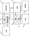
图1是本发明的超声波诊断装置的框图;Fig. 1 is the block diagram of ultrasonic diagnostic apparatus of the present invention;

图2是表示本发明的超声波诊断装置的框图的详细情况的图;FIG. 2 is a diagram showing details of a block diagram of the ultrasonic diagnostic apparatus of the present invention;

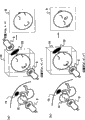
图3是表示本发明的显示处理的概念图以及第四实施方式的图;FIG. 3 is a conceptual diagram showing a display process of the present invention and a diagram showing a fourth embodiment;

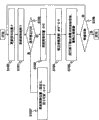
图4是表示本发明的显示处理的流程图;Fig. 4 is a flowchart showing display processing of the present invention;

图5是表示本发明的第二实施方式的图;Fig. 5 is a diagram showing a second embodiment of the present invention;

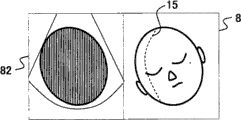
图6是表示本发明的第三实施方式的图;FIG. 6 is a diagram showing a third embodiment of the present invention;

图7是表示本发明的第五实施方式的图。Fig. 7 is a diagram showing a fifth embodiment of the present invention.

具体实施方式Detailed ways

参照附图,对应用本发明而构成的超声波诊断装置的第一实施方式进行说明。该实施方式是利用与超声波探头连接的位置传感器,不依赖于超声波探头的位置地进行从固定方向观察的目标部位的显示的例子。A first embodiment of an ultrasonic diagnostic apparatus configured by applying the present invention will be described with reference to the drawings. This embodiment is an example in which a target site viewed from a fixed direction is displayed without depending on the position of the ultrasonic probe by using a position sensor connected to the ultrasonic probe.

图1中表示本实施方式的超声波诊断装置的框图。图1所示的超声波诊断装置1包括:排列有收发超声波的振动器元件的超声波探头2;通过超声波探头2向被检体50送波超声波信号,并对所接收的超声波信号进行调相相加、Log压缩等处理的超声波收发部3;安装于超声波探头2的位置传感器(终端)4;利用磁信号等对位置传感器4的位置进行检测的信号源(source)5;由信号源5分析位置传感器4的位置信息,推算对三维超声波图像数据进行修正的修正参数的位置信息分析部6;对来自超声波收发部3的三维超声波图像数据进行滤波处理、扫描变换等处理,利用来自位置信息分析部6的修正参数进行三维超声波图像的重构的超声波图像构成部7;进行图像的显示的显示器8;与所有模块连接来进行控制的控制部9;和向控制器9发出指示的控制面板10。FIG. 1 shows a block diagram of an ultrasonic diagnostic apparatus according to this embodiment. Ultrasonic diagnostic apparatus 1 shown in Fig. 1 comprises: the ultrasonic probe 2 that is arranged with the vibrator element of transmitting and receiving ultrasonic wave; Send wave ultrasonic signal to object 50 through ultrasonic probe 2, and carry out phase modulation and addition to the received ultrasonic signal , Log compression and other processing ultrasonic transceivers 3; the position sensor (terminal) 4 installed in the ultrasonic probe 2; the signal source (source) 5 that uses magnetic signals or the like to detect the position of the position sensor 4; the position is analyzed by the signal source 5 The position information of the sensor 4 is used to estimate the position information analysis unit 6 that corrects the correction parameters for the three-dimensional ultrasonic image data; the three-dimensional ultrasonic image data from the ultrasonic transceiver unit 3 is processed by filtering, scanning conversion, etc. 6 correction parameters for reconstructing the three-dimensional ultrasound image; the display 8 for displaying the image; the control unit 9 connected to all modules for control;

另外,如图2所示,位置信息分析部6中具备:用于存储超声波探头2的位置的存储器61、和根据存储器61中存储的位置信息推算修正参数等的运算部62,超声波图像构成部7中具备:用于存储二维超声波图像或三维超声波图像的存储器71、根据修正参数等对三维超声波图像数据进行修正来构成三维超声波图像的图像处理运算部72。In addition, as shown in FIG. 2 , the positional information analysis unit 6 is provided with: a memory 61 for storing the position of the ultrasonic probe 2, and a computing unit 62 for estimating and correcting parameters based on the positional information stored in the memory 61, and the ultrasonic image forming unit 7 includes a memory 71 for storing two-dimensional ultrasonic images or three-dimensional ultrasonic images, and an image processing calculation unit 72 for correcting three-dimensional ultrasonic image data based on correction parameters and the like to form a three-dimensional ultrasonic image.

超声波探头2沿长轴方向排列1~m沟道(channel)份的振动器元件,并且沿短轴方向也切断为k个而排列1~k沟道份振动器元件。超声波探头2通过改变对各振动器元件(1~k沟道)赋予的延迟时间,从而在长轴方向和短轴方向上形成送波或受波的焦点(focus)。另外,超声波探头2通过改变对短轴方向的各振动器元件赋予的超声波发送信号的振幅来实施送波加权,通过改变来自短轴方向的各振动器元件的超声波接收信号的放大率或衰减率来实施受波加权。进而,通过使短轴方向的各个振动器元件接通、断开,可进行口径控制。此外,超声波探头2也可采用机械式超声波探头,所述机械式超声波探头一边机械地使振动器沿短轴方向往复移动,一边扫描超声波来取得三维超声波图像数据。In the ultrasonic probe 2 , vibrator elements for 1 to m channels are arranged along the long axis direction, and vibrator elements for 1 to k channels are arranged along the short axis direction by cutting into k pieces. The ultrasonic probe 2 forms a focus (focus) of transmitting or receiving waves in the long-axis direction and the short-axis direction by changing the delay time given to each vibrator element (1 to k channels). In addition, the ultrasonic probe 2 implements wave transmission weighting by changing the amplitude of the ultrasonic transmission signal given to each vibrator element in the short-axis direction, and by changing the amplification factor or attenuation rate of the ultrasonic reception signal from each vibrator element in the short-axis direction. To implement wave weighting. Furthermore, aperture control can be performed by turning on and off each vibrator element in the minor axis direction. In addition, the ultrasonic probe 2 may be a mechanical ultrasonic probe that scans ultrasonic waves while mechanically reciprocating a vibrator in the short-axis direction to obtain three-dimensional ultrasonic image data.

当利用该超声波探头2来获得三维超声波图像时,超声波图像构成部7内的存储器71首先扫描超声波并存储二维超声波图像数据。然后,超声波图像构成部7逐帧按顺序读出二维超声波图像数据,由超声波构成部7内的加法器合并各帧来构成三维超声波图像。此时,实现二维超声波图像数据与超声波探头2的位置数据的匹配。When the ultrasonic probe 2 is used to obtain a three-dimensional ultrasonic image, the memory 71 in the ultrasonic image forming unit 7 first scans the ultrasonic wave and stores two-dimensional ultrasonic image data. Then, the ultrasonic image constructing unit 7 sequentially reads out the two-dimensional ultrasonic image data frame by frame, and combines the frames by an adder in the ultrasonic constructing unit 7 to form a three-dimensional ultrasonic image. At this time, matching of the two-dimensional ultrasonic image data and the position data of the ultrasonic probe 2 is realized.

在该超声波探头2上安装有位置传感器4。位置传感器4具有磁传感器,该磁传感器检测从安装在底座(bed)等位置的信号源5产生的例如磁信号。由位置传感器4检测源坐标系S中的超声波探头2的三维位置以及倾斜度。源坐标系S是以信号源5为原点So的三维正交坐标系,使X轴与被检体横放的底座的较短方向一致,使Y轴与底座的较长方向一致,使Z轴与铅垂方向一致。另外,源坐标系S并不限定于三维正交坐标系,只要是能确定超声波探头2的位置的坐标系即可。另外,位置传感器4并不限定于利用磁场,例如也可利用光。A position sensor 4 is attached to the ultrasonic probe 2 . The position sensor 4 has a magnetic sensor that detects, for example, a magnetic signal generated from a signal source 5 installed at a position such as a bed. The three-dimensional position and inclination of the ultrasonic probe 2 in the source coordinate system S are detected by the position sensor 4 . The source coordinate system S is a three-dimensional orthogonal coordinate system with the signal source 5 as the origin So, so that the X-axis is consistent with the shorter direction of the base on which the subject is placed horizontally, the Y-axis is consistent with the longer direction of the base, and the Z-axis consistent with the vertical direction. In addition, the source coordinate system S is not limited to a three-dimensional orthogonal coordinate system, and may be any coordinate system as long as the position of the ultrasonic probe 2 can be specified. In addition, the position sensor 4 is not limited to using a magnetic field, and may use light, for example.

图3中表示本实施方式中的图像处理的概念图。如图3(a)所示,位置A(a,b,c)是拍摄目标部位12的正面像的位置,但三维超声波图像中在位置A(a,b,c)处显示有障碍物13。因此,将超声波探头2设置到位置B(a’,b’,c’),对目标部位12扫描超声波。由于在超声波探头2与目标部位12之间不存在障碍物13,因此通过扫描获得的三维超声波图像数据14中不包含障碍物13。这样,若将超声波探头2设置到位置B(a’,b’,c’)进行重构,则显示目标部位12的侧面像。FIG. 3 shows a conceptual diagram of image processing in this embodiment. As shown in FIG. 3( a ), the position A (a, b, c) is the position where the frontal image of the target part 12 is taken, but the obstacle 13 is displayed at the position A (a, b, c) in the three-dimensional ultrasonic image. . Therefore, the ultrasonic probe 2 is set to the position B (a', b', c'), and the target site 12 is scanned with ultrasonic waves. Since there is no obstacle 13 between the ultrasound probe 2 and the target site 12 , the three-dimensional ultrasound image data 14 obtained by scanning does not include the obstacle 13 . In this way, when the ultrasonic probe 2 is set to the position B (a', b', c') for reconstruction, the side view of the target site 12 is displayed.

因此,位置信息分析部6内的存储器61存储由位置传感器4获得的超声波探头2的位置,位置信息分析部6内的运算部62分析存储器61中存储的位置A(a,b,c)与位置B(a’,b’,c’)的位置关系。超声波图像构成部7内的图像处理运算部72根据该位置关系进行图像变换,使得从位置B(a’,b’,c’)获得的三维超声波图像数据变为从位置A(a,b,c)获得的图像数据,从而构成三维超声波图像。此外,位置B(a’,b’,c’)也可存储于存储器61。Therefore, the memory 61 in the position information analysis part 6 stores the position of the ultrasonic probe 2 obtained by the position sensor 4, and the calculation part 62 in the position information analysis part 6 analyzes the position A (a, b, c) stored in the memory 61 and Positional relationship of position B (a', b', c'). The image processing unit 72 in the ultrasonic image composing unit 7 performs image conversion according to the positional relationship, so that the three-dimensional ultrasonic image data obtained from the position B (a', b', c') becomes from the position A (a, b, c) The acquired image data to form a three-dimensional ultrasound image. In addition, the position B (a', b', c') can also be stored in the memory 61.

具体而言,位置信息分析部6内的运算部62将超声波探头2的位置A(a,b,c)设定为成为三维超声波图像的显示位置的变换矩阵。然后,运算部62设定改变了超声波探头2的方向后的位置B(a’,b’,c’)的变换矩阵。接着,根据位置A(a,b,c)和位置B(a’,b’,c’)的变换矩阵推算旋转立体角度的变化量(修正参数)。图像处理运算部72基于修正参数进行三维超声波图像的坐标变换,来改变三维超声波图像的显示方向。Specifically, the calculation unit 62 in the position information analysis unit 6 sets the position A (a, b, c) of the ultrasound probe 2 as a transformation matrix that becomes the display position of the three-dimensional ultrasound image. Then, the computing unit 62 sets a transformation matrix of the position B (a', b', c') after changing the direction of the ultrasonic probe 2 . Next, the amount of change in the rotation solid angle (correction parameter) is estimated from the transformation matrix of the position A (a, b, c) and the position B (a', b', c'). The image processing calculation unit 72 performs coordinate transformation of the three-dimensional ultrasonic image based on the correction parameters, and changes the display direction of the three-dimensional ultrasonic image.

在此,对位置信息分析部6中的修正参数的计算方法进行说明。从位置传感器4的基准轴开始,设表示位置A(a,b,c)的超声波探头2的位置和方向的变换矩阵S为式(1),设表示位置B(a’,b’,c’)的超声波探头2的位置和方向的变换矩阵D为式(2)。该变换矩阵存储于存储器61。然后,运算部62设在超声波探头2任意确定的位置A(a,b,c)处针对三维超声波图像数据14的旋转矩阵V为式(3),根据式(5),将从位置A(a,b,c)到位置B(a’,b’,c’)的变换矩阵X设定为式(6)。因此,由式(4)表示的修正参数M、变换矩阵X、旋转矩阵V的关系如式(7)所示。Here, the calculation method of the correction parameter in the positional information analysis unit 6 will be described. Starting from the reference axis of the position sensor 4, the transformation matrix S of the position and direction of the ultrasonic probe 2 representing the position A (a, b, c) is assumed to be formula (1), and the position B (a', b', c ') The transformation matrix D of the position and direction of the ultrasonic probe 2 is formula (2). This transformation matrix is stored in the memory 61 . Then, the calculation unit 62 assumes that the rotation matrix V of the three-dimensional ultrasonic image data 14 at the position A (a, b, c) arbitrarily determined by the ultrasonic probe 2 is expressed as formula (3), and according to formula (5), the rotation matrix V from the position A ( The transformation matrix X from a, b, c) to position B (a', b', c') is set as Equation (6). Therefore, the relationship between the correction parameter M, the transformation matrix X, and the rotation matrix V expressed by the formula (4) is as shown in the formula (7).

在此,为了便于计算,当根据旋转成分仅进行显示角度修正时,在式(1)中设(ds1,ds2,ds3)=(0,0,0),在式(2)中,设(dv1,dv2,dv3)=(0,0,0),在式(3)中设(dd1,dd2,dd3)=(0,0,0)。Here, for the convenience of calculation, when only the display angle is corrected according to the rotation component, set (ds1, ds2, ds3) = (0, 0, 0) in formula (1), and set ( dv1, dv2, dv3) = (0, 0, 0), and (dd1, dd2, dd3) = (0, 0, 0) in formula (3).

因此,由运算部62根据式(8)推算修正参数M。即,在超声波探头2的位置B(a’,b’,c’)处获得的三维超声波图像数据14,利用由修正参数M表示的坐标变换,以三维超声波图像的中央为原点进行旋转。图像处理运算部72通过重构该旋转后的三维超声波图像,可获得来自位置A(a,b,c)方向的三维超声波图像。Therefore, the correction parameter M is estimated by the computing unit 62 based on Equation (8). That is, the three-dimensional ultrasonic image data 14 obtained at the position B (a', b', c') of the ultrasonic probe 2 is rotated with the center of the three-dimensional ultrasonic image as the origin by coordinate transformation represented by the correction parameter M. The image processing calculation unit 72 can obtain a three-dimensional ultrasonic image from the direction of position A (a, b, c) by reconstructing the rotated three-dimensional ultrasonic image.

[数式1][Formula 1]

SS == aa sthe s 11 bb sthe s 11 cc sthe s 11 dd sthe s 11 aa sthe s 22 bb sthe s 22 cc sthe s 22 dd sthe s 22 aa sthe s 33 bb sthe s 33 cc sthe s 33 dd sthe s 33 00 00 00 11 -- -- -- (( 11 ))

[数式2][Formula 2]

DD. == aa dd 11 bb dd 11 cc dd 11 dd dd 11 aa dd 22 bb dd 22 cc dd 22 dd dd 22 aa dd 33 bb dd 33 cc dd 33 dd dd 33 00 00 00 11 -- -- -- (( 22 ))

[数式3][Formula 3]

VV == aa vv 11 bb vv 11 cc vv 11 dd vv 11 aa vv 22 bb vv 22 cc vv 22 dd vv 22 aa vv 33 bb vv 33 cc vv 33 dd vv 33 00 00 00 11 -- -- -- (( 33 ))

[数式4][Formula 4]

Mm == aa mm 11 bb mm 11 cc mm 11 dd mm 11 aa mm 22 bb mm 22 cc mm 22 dd mm 22 aa mm 33 bb mm 33 cc mm 33 dd mm 33 00 00 00 11 -- -- -- (( 44 ))

[数式5][Formula 5]

D=S·X...(5)D=S·X...(5)

[数式6][Formula 6]

X=D·S-1...(6)X=D·S -1 ...(6)

[数式7][Formula 7]

M=X-1·V...(7)M=X -1 ·V...(7)

[数式8][Formula 8]

M=D-1·S·V...(8)M=D -1 ·S·V...(8)

图4中表示用于进行位置修正参数的推算的步骤。在开始超声波检查后,位置信息分析部6内的运算部62进行表示当前的超声波探头2的位置的变换矩阵D的更新(S100),然后进行从控制面板10输入的旋转矩阵V的更新(S101)。接着,当与位置A(a,b,c)一致地对在位置B(a’,b’,c’)获得的三维超声波图像进行修正的功能、即显示修正功能打开时(S102),设定使表示移动前(位置A(a,b,c))的超声波探头2的位置的变换矩阵S固定,使变换矩阵D可变(S103’)。即,成为变换矩阵S≠变换矩阵D。然后,在超声波图像构成部7内的图像处理运算部72中,利用基于在(S104)中推算出的修正参数M的坐标变换,生成三维超声波图像,并在显示器8上进行显示。在控制部9中若未选择检查结束,则从处理(S100)开始再次进行处理,若已选择检查结束则结束处理(S106)。FIG. 4 shows the procedure for estimating the position correction parameter. After the ultrasound examination is started, the calculation unit 62 in the position information analysis unit 6 updates the transformation matrix D representing the current position of the ultrasound probe 2 (S100), and then updates the rotation matrix V input from the control panel 10 (S101 ). Next, when the function of correcting the three-dimensional ultrasonic image obtained at the position B (a', b', c') in accordance with the position A (a, b, c), that is, the display correction function is turned on (S102), set The transformation matrix S representing the position of the ultrasonic probe 2 before movement (position A (a, b, c)) is fixed, and the transformation matrix D is variable (S103'). That is, transformation matrix S≠transformation matrix D. Then, in the image processing unit 72 in the ultrasonic image forming unit 7 , a three-dimensional ultrasonic image is generated by coordinate transformation based on the correction parameter M estimated in ( S104 ), and displayed on the monitor 8 . If the end of inspection is not selected in the control unit 9, the processing is resumed from the processing (S100), and if the end of the inspection is selected, the processing is ended (S106).

此外,在不应用本发明时,不进行使显示位置与位置A(a,b,c)一致地修正三维超声波图像。即,当显示修正功能未打开时(S102),位置信息分析部6内的运算部62将变换矩阵D代入表示移动前(位置A(a,b,c))的超声波探头2的位置的变换矩阵S(S103),通过上述式子推算修正参数M(S104)。此时,由于变换矩阵S=变换矩阵D,因此,修正参数M成为仅进行从控制面板10输入的旋转矩阵V的变换矩阵。In addition, when the present invention is not applied, the three-dimensional ultrasonic image is not corrected so that the display position matches the position A (a, b, c). That is, when the display correction function is not turned on (S102), the calculation unit 62 in the position information analysis unit 6 substitutes the transformation matrix D into the transformation representing the position of the ultrasonic probe 2 before moving (position A (a, b, c)). The matrix S (S103), calculates the correction parameter M by the above formula (S104). At this time, since transformation matrix S=transformation matrix D, the correction parameter M becomes a transformation matrix for performing only the rotation matrix V input from the control panel 10 .

当从控制面板10进行操作使显示修正功能打开时(S102),由于表示移动前(位置A(a,b,c))的超声波探头2的位置的变换矩阵S不被更新,因此在处理(S104)中推算的修正参数M成为:从表示当前的超声波探头2的位置的变换矩阵D向表示移动前的超声波探头2的位置A(a,b,c)的变换矩阵S移动,进行从控制面板10输入的旋转矩阵V的变换矩阵。即,所述修正参数M成为如下参数:对在位置A(a,b,c)的超声波探头2的位置扫描的三维超声波图像数据进行了基于从控制面板10输入的旋转矩阵V的坐标变换后,从与该坐标变换后的显示方向相同的位置,对在当前的超声波探头2的位置B(a’,b’,c’)扫描的三维超声波图像数据重构三维超声波图像。表示当前的超声波探头2的位置B(a’,b’,c’)的变换矩阵D在每次扫描时被更新,但表示移动前的超声波探头2的位置A(a,b,c)的变换矩阵S在显示修正未打开的期间不会被更新,因此,能始终保持在移动前的超声波探头2的位置A(a,b,c)观察时的显示状态,而与当前的超声波探头2的位置B(a’,b’,c’)无关。When the operation of the control panel 10 is performed to turn on the display correction function (S102), since the transformation matrix S representing the position of the ultrasonic probe 2 before the movement (position A (a, b, c)) is not updated, the processing ( The correction parameter M calculated in S104) becomes: from the transformation matrix D representing the position of the current ultrasonic probe 2 to the transformation matrix S representing the position A (a, b, c) of the ultrasonic probe 2 before moving, the slave control The transformation matrix of the rotation matrix V input by the panel 10 . That is, the correction parameter M is a parameter obtained by performing coordinate transformation based on the rotation matrix V input from the control panel 10 for the three-dimensional ultrasonic image data scanned at the position of the ultrasonic probe 2 at the position A (a, b, c). A three-dimensional ultrasonic image is reconstructed from the three-dimensional ultrasonic image data scanned at the current position B (a', b', c') of the ultrasonic probe 2 from the same position as the display direction after the coordinate transformation. The transformation matrix D representing the position B (a', b', c') of the current ultrasound probe 2 is updated every scan, but the transformation matrix D representing the position A (a, b, c) of the ultrasound probe 2 before moving The transformation matrix S will not be updated during the period when the display correction is not turned on. Therefore, it can always maintain the display state when observing the position A (a, b, c) of the ultrasonic probe 2 before moving, and it is different from the current ultrasonic probe 2 The position of B(a', b', c') is irrelevant.

这样,位置信息分析部6内的运算部62根据超声波探头2的位置A(a,b,c)和位置B(a’,b’,c’)的位置信息,使三维超声波图像数据14旋转,推算获得与位置A(a,b,c)的三维超声波图像相同的图像用的修正参数。然后,超声波图像构成图7内的图像处理运算部72利用该修正参数,对三维超声波图像数据14进行重构,由此自动获得三维超声波图像。In this way, the calculation unit 62 in the position information analysis unit 6 rotates the three-dimensional ultrasonic image data 14 based on the position information of the position A (a, b, c) and position B (a′, b′, c′) of the ultrasonic probe 2 , to estimate the correction parameters for obtaining the same image as the three-dimensional ultrasonic image at position A (a, b, c). Then, the image processing unit 72 in FIG. 7 reconstructs the three-dimensional ultrasonic image data 14 using the correction parameters, thereby automatically obtaining a three-dimensional ultrasonic image.

在此,说明对三维超声波图像数据14进行旋转变换的其他方式。首先,位置信息分析部6内的存储器61显示目标部位12的正面像,存储作为显示位置的位置A(a,b,c)。然后,存储器61存储超声波图像中不含障碍物13的位置B(a’,b’,c’)。这些位置信息被送到位置信息分析部6内的运算部62,运算部62计算位置B(a’,b’,c’)相对于位置A(a,b,c)的位置变化量以及旋转立体角的位移量。而后,图像处理运算部72使三维超声波图像旋转该变化后的超声波探头2的位置和角度,对位置A(a,b,c)成为显示位置的三维超声波图像进行显示。Here, another method of rotationally transforming the three-dimensional ultrasonic image data 14 will be described. First, the memory 61 in the positional information analysis unit 6 displays the frontal image of the target site 12 and stores the position A (a, b, c) as the displayed position. Then, the memory 61 stores a position B (a', b', c') that does not contain the obstacle 13 in the ultrasonic image. These position information are sent to the calculation unit 62 in the position information analysis unit 6, and the calculation unit 62 calculates the position change and the rotation of the position B (a', b', c') relative to the position A (a, b, c). The displacement of the solid angle. Then, the image processing computing unit 72 rotates the three-dimensional ultrasonic image by the changed position and angle of the ultrasonic probe 2, and displays the three-dimensional ultrasonic image whose position A (a, b, c) is the display position.

具体而言,当在位置A(a,b,c)显示的平面图像的法线矢量与在位置B(a’,b’,c’)显示的平面图像的法线矢量,是在三维超声波图像数据上相交时以交点为中心的旋转立体角的位移量。该位移量被分解为绕X轴的旋转、绕Y轴的旋转和绕Z轴的旋转,各旋转由下面表示的旋转矩阵来表现。Specifically, when the normal vector of the planar image displayed at position A (a, b, c) and the normal vector of the planar image displayed at position B (a', b', c') are in the three-dimensional ultrasound The displacement of the solid angle of rotation centered on the intersection point when the image data is intersected. This displacement amount is decomposed into rotation around the X axis, rotation around the Y axis, and rotation around the Z axis, and each rotation is represented by a rotation matrix shown below.

首先,绕X轴的角度θ1的旋转由下式表示,First, the rotation around the X-axis at an angle θ1 is represented by the following equation,

[数式9][Formula 9]

Xx YY ZZ == 11 00 00 00 coscos θθ 11 sinsin θθ 11 00 -- sinsin θθ 11 coscos θθ 11 xx ythe y zz -- -- -- (( 99 ))

绕Y轴的角度θ2的旋转由下式表示,The rotation around the Y-axis at an angle θ2 is expressed by,

[数式10][Formula 10]

Xx YY ZZ == coscos θθ 22 00 -- sinsin θθ 22 00 11 00 sinsin θθ 22 00 coscos θθ 22 xx ythe y zz -- -- -- (( 1010 ))

绕Z轴的角度θ3的旋转由下式表示。The rotation around the Z-axis at an angle θ3 is represented by the following equation.

[数式11][Formula 11]

Xx YY ZZ == coscos θθ 33 sinsin θθ 33 00 -- sinsin θθ 33 coscos θθ 33 00 00 00 11 xx ythe y zz -- -- -- (( 1111 ))

因此,在上述旋转矩阵中分别利用单位矢量(1,0,0)、Y方向的单位矢量(0,1,0)、Z方向的单位矢量(0,0,1),使位置B(a’,b’,c’)的三维超声波图像数据14向X方向、Y方向、Z方向旋转变换,从而使三维超声波图像数据14自位置B(a’,b’,c’)向位置A(a,b,c)旋转变换。基于该旋转后的三维超声波图像数据14,重构三维超声波图像,由此能从位置A(a,b,c)的显示方向显示三维超声波图像。Therefore, using the unit vector (1, 0, 0), the unit vector (0, 1, 0) in the Y direction, and the unit vector (0, 0, 1) in the Z direction in the above rotation matrix, the position B(a ', b', c') three-dimensional ultrasonic image data 14 to the X direction, Y direction, Z direction rotation transformation, so that the three-dimensional ultrasonic image data 14 from position B (a', b', c') to position A ( a, b, c) Rotation transformation. By reconstructing the three-dimensional ultrasonic image based on the rotated three-dimensional ultrasonic image data 14, the three-dimensional ultrasonic image can be displayed from the display direction of the position A (a, b, c).

这样,根据第一实施方式,基于超声波探头2的位置A(a,b,c)与位置B(a’,b’,c’)的位置关系,图像处理运算部72对从位置B(a’,b’,c’)获得的三维超声波图像数据进行变换,从而能从位置A(a,b,c)的显示方向显示三维超声波图像。即,一旦指定超声波探头2的某一位置,则即使移动超声波探头2,也能显示从该位置观察的三维超声波图像。Thus, according to the first embodiment, based on the positional relationship between the position A (a, b, c) and the position B (a', b', c') of the ultrasonic probe 2, the image processing calculation unit 72 calculates the value from the position B (a ', b', c') obtained by converting the three-dimensional ultrasonic image data, so that the three-dimensional ultrasonic image can be displayed from the display direction of the position A (a, b, c). That is, once a certain position of the ultrasonic probe 2 is designated, even if the ultrasonic probe 2 is moved, a three-dimensional ultrasonic image viewed from the position can be displayed.

另外,即使超声波探头2发生抖动等,即从位置B(a’,b’,c’)获得的三维超声波图像数据发生变化,由于位置A(a,b,c)固定,因此也能从位置A(a,b,c)的位置稳定显示三维超声波图像。In addition, even if the ultrasonic probe 2 shakes, that is, the three-dimensional ultrasonic image data obtained from the position B (a', b', c') changes, since the position A (a, b, c) is fixed, it can be obtained from the position A (a, b, c). A(a, b, c) position stabilized display of 3D ultrasound images.

下面,在图5中表示第二实施方式。第二实施方式与第一实施方式的不同之处在于,对表示显示位置的方向指示标记30进行三维显示,显示与该方向指示标记30对应的目标部位12。在显示器8上,显示三维超声波图像和辅助画面81。辅助画面81显示从抵接超声波探头2的位置B(a’,b’,c’)观察的三维超声波图像、和表示显示方向的方向指示标记30。利用控制面板10,可使该方向指示标记30在目标部位12的周围三维地移动。另外,方向指示标记30朝向目标部位12的中心点。Next, a second embodiment is shown in FIG. 5 . The second embodiment differs from the first embodiment in that the direction indicator mark 30 indicating the display position is three-dimensionally displayed, and the target site 12 corresponding to the direction indicator mark 30 is displayed. On the display 8, a three-dimensional ultrasonic image and an auxiliary screen 81 are displayed. The auxiliary screen 81 displays a three-dimensional ultrasonic image viewed from a position B (a', b', c') in contact with the ultrasonic probe 2 and a direction indication mark 30 indicating the display direction. The direction indicator mark 30 can be three-dimensionally moved around the target site 12 using the control panel 10 . In addition, the direction indicator mark 30 is directed towards the center point of the target site 12 .

在此,设方向指示标记30的位置为位置C(a”,b”,c”):显示位置。图5的方向指示标记30是从下方拍摄目标部位12的位置。位置信息分析部6内的运算部62以与上述第一实施方式相同的方式计算位置B(a’,b’,c’)相对于位置C(a”,b”,c”)的位置的修正参数,或计算变化量以及旋转立体角的位移量。然后,图像处理运算部72构成旋转后的三维超声波图像,在显示器8上显示位置C(a”,b”,c”)即来自方向指示标记30方向的三维超声波图像。因此,能够观察来自设定的方向指示标记30方向的三维超声波图像。Here, let the position of the direction indicator mark 30 be position C (a ", b ", c"): display position. The direction indicator mark 30 of FIG. The computing unit 62 of the above-mentioned first embodiment calculates the correction parameter of the position of the position B (a', b', c') relative to the position C (a", b", c") in the same manner as the above-mentioned first embodiment, or calculates the change amount and the displacement of the rotating solid angle. Then, the image processing operation unit 72 constructs the rotated three-dimensional ultrasound image, and displays the three-dimensional ultrasound image at the position C (a", b", c") on the display 8, that is, the three-dimensional ultrasound image from the direction of the direction indicator mark 30. Therefore, it is possible to observe the three-dimensional ultrasound image from the device. A three-dimensional ultrasound image of the direction of the designated direction indicator marker 30.

另外,在将超声波探头2固定到被检体50上的状态下,利用控制面板10,使方向指示标记30移动。伴随该方向指示标记30的移动,位置信息分析部6内的运算部62实时地计算位置的变化量以及旋转立体角的位移量。然后,基于位置的变化量以及旋转立体角的位移量,实时地构成旋转后的三维超声波图像,由此能够将方向指示标记30的方向的三维超声波图像始终显示在显示器8上。根据第二实施方式,可进行方向指示标记30的方向的三维超声波图像的调整。In addition, the direction indicating mark 30 is moved by using the control panel 10 in a state where the ultrasonic probe 2 is fixed to the subject 50 . Along with the movement of the direction indicator mark 30 , the calculation unit 62 in the position information analysis unit 6 calculates the amount of change in the position and the displacement amount of the solid angle of rotation in real time. Then, the rotated three-dimensional ultrasonic image is constructed in real time based on the amount of change in the position and the displacement of the solid angle of rotation, so that the three-dimensional ultrasonic image in the direction of the direction indicator mark 30 can always be displayed on the display 8 . According to the second embodiment, the adjustment of the three-dimensional ultrasonic image of the direction of the direction indicator mark 30 can be performed.

下面,在图6中表示第三实施方式。第三实施方式与第一实施方式和第二实施方式的不同之处在于,同时显示三维超声波图像和B模式像。该B模式像是从超声波探头2的扫描方向拍摄的像。Next, a third embodiment is shown in FIG. 6 . The third embodiment differs from the first and second embodiments in that a three-dimensional ultrasonic image and a B-mode image are simultaneously displayed. This B-mode image is an image taken from the scanning direction of the ultrasonic probe 2 .

虚线15是显示器8上显示的三维超声波图像所对应的B模式像的切面。可通过控制面板10移动虚线15,位置信息分析部6识别虚线15的位置信息,超声波图像构成部7内的图像处理运算部72从三维超声波图像数据14中选择与虚线15对应的截面的B模式像,显示到显示器8上。这样,能同时显示被检体50的外周面和内部,想要观察B模式像时也可适当变更。因此,根据第三实施方式,基于超声波探头2的位置A(a,b,c)与位置B(a’,b’,c’)的位置关系,对从位置B(a’,b’,c’)获得的三维超声波图像数据进行变换,从而能从位置A(a,b,c)的显示方向显示二维超声波图像。即,一旦指定超声波探头2的某一位置,则即使移动超声波探头2,也能显示从该位置观察的二维超声波图像。The dotted line 15 is the cut plane of the B-mode image corresponding to the three-dimensional ultrasonic image displayed on the display 8 . The dotted line 15 can be moved through the control panel 10, the position information analysis unit 6 recognizes the position information of the dotted line 15, and the image processing operation unit 72 in the ultrasonic image forming unit 7 selects the B-mode of the section corresponding to the dotted line 15 from the three-dimensional ultrasonic image data 14 Like, show on the monitor 8. In this way, the outer peripheral surface and the inside of the subject 50 can be displayed at the same time, and it can be changed appropriately when it is desired to observe a B-mode image. Therefore, according to the third embodiment, based on the positional relationship between the position A (a, b, c) and the position B (a', b', c') of the ultrasonic probe 2, the slave position B (a', b', c′) The obtained three-dimensional ultrasonic image data is converted so that the two-dimensional ultrasonic image can be displayed from the display direction of the position A (a, b, c). That is, once a certain position of the ultrasonic probe 2 is designated, even if the ultrasonic probe 2 is moved, a two-dimensional ultrasonic image viewed from the position can be displayed.

另外,虚线15的初始设定设为超声波探头2的扫描面,但也可追随上述的位置A(a,b,c)、位置B(a’,b’,c’)、位置C(a”,b”,c”)、或方向指示标记30。In addition, the initial setting of the dotted line 15 is the scanning surface of the ultrasonic probe 2, but it can also follow the above-mentioned position A (a, b, c), position B (a', b', c'), position C (a ", b", c"), or direction indicator mark 30.

下面,利用图3对第四实施方式进行说明。第四实施方式与第一~第三实施方式的不同之处在于,合成两个以上三维超声波图像。Next, a fourth embodiment will be described using FIG. 3 . The fourth embodiment differs from the first to third embodiments in that two or more three-dimensional ultrasonic images are synthesized.

在从位置B(a’,b’,c’)扫描超声波获得的三维超声波图像数据14中,超声波探头2侧的三维超声波图像数据充分,但位置B(a’,b’,c’)的点对称位置即背面侧的三维超声波图像数据不足。在图3中,超声波探头2抵接的右耳侧的三维超声波图像数据充分,但目标部位12的左耳侧的三维超声波图像数据不足。因此,将三维超声波图像数据不足的一侧的三维超声波图像数据14预先存储到存储器17中,图像处理运算部72对存储器71中存储的三维超声波图像和实时获得的三维超声波图像进行合成。In the three-dimensional ultrasonic image data 14 obtained by scanning ultrasound from the position B (a', b', c'), the three-dimensional ultrasonic image data on the side of the ultrasonic probe 2 is sufficient, but the three-dimensional ultrasonic image data of the position B (a', b', c') The three-dimensional ultrasonic image data of the point symmetrical position, that is, the back side is insufficient. In FIG. 3 , the three-dimensional ultrasonic image data on the right ear side where the ultrasonic probe 2 is in contact is sufficient, but the three-dimensional ultrasonic image data on the left ear side of the target site 12 is insufficient. Therefore, the 3D ultrasonic image data 14 on the side with insufficient 3D ultrasonic image data is stored in the memory 17 in advance, and the image processing calculation unit 72 synthesizes the 3D ultrasonic image stored in the memory 71 and the 3D ultrasonic image obtained in real time.

对该合成功能进行具体说明。超声波图像构成部7内的图像处理运算部72具有对两个以上三维超声波图像进行合成的功能。首先,向被检体50扫描超声波,获得三维超声波图像,存储到存储器71中。此时,根据位置传感器4的位置信息,设定三维超声波图像的基准点,将该基准点存储到存储器71中。然后,改变超声波探头2的位置,向被检体50扫描超声波,实时获取三维超声波图像。然后,图像处理运算部72使存储器71所存储的三维超声波图像的基准点与实时的三维超声波图像的基准点一致,从而使所存储的三维超声波图像与实时的三维超声波图像重叠。当重叠两个以上三维超声波图像时,优先显示亮度大的三维超声波图像。另外,重叠的三维超声波图像也可以是三个以上。The synthesis function will be described in detail. The image processing operation unit 72 in the ultrasonic image forming unit 7 has a function of synthesizing two or more three-dimensional ultrasonic images. First, ultrasound is scanned on the subject 50 to obtain a three-dimensional ultrasound image, which is stored in the memory 71 . At this time, the reference point of the three-dimensional ultrasonic image is set based on the position information of the position sensor 4 , and the reference point is stored in the memory 71 . Then, the position of the ultrasonic probe 2 is changed, the ultrasonic wave is scanned on the subject 50, and a three-dimensional ultrasonic image is acquired in real time. Then, the image processing unit 72 makes the reference point of the three-dimensional ultrasonic image stored in the memory 71 coincide with the reference point of the real-time three-dimensional ultrasonic image, thereby superimposing the stored three-dimensional ultrasonic image and the real-time three-dimensional ultrasonic image. When two or more three-dimensional ultrasound images are superimposed, the three-dimensional ultrasound image with high brightness is preferentially displayed. In addition, three or more three-dimensional ultrasound images may be superimposed.

这样,存储器71预先对不足一侧的三维超声波图像数据进行存储,图像处理运算部72利用该三维超声波图像数据对实时三维超声波图像进行修正。因此,根据第四实施方式,能显示在任何角度亮度都均匀的三维超声波图像。In this way, the memory 71 stores in advance the three-dimensional ultrasonic image data of the short side, and the image processing calculation unit 72 uses the three-dimensional ultrasonic image data to correct the real-time three-dimensional ultrasonic image. Therefore, according to the fourth embodiment, it is possible to display a three-dimensional ultrasonic image with uniform brightness at any angle.

下面,利用图7,对第五实施方式进行说明。第五实施方式与第一~第四实施方式的不同之处在于,设定对三维超声波图像数据进行部分删除的预切割线(precut line)。Next, a fifth embodiment will be described using FIG. 7 . The fifth embodiment differs from the first to fourth embodiments in that a precut line for partially deleting three-dimensional ultrasonic image data is set.

左图31是与在显示器8上显示的预切割设定画面相关的图。右图32是与超声波图像构成部7内的图像处理运算部72所进行的三维超声波图像数据处理相关的图。从超声波探头2的位置A(a,b,c)获得的三维超声波图像数据是由设定的ROI35指定的范围内的三维超声波图像数据。即,该ROI35具有立体的区域。并且,在三维超声波图像数据中包含与胎儿36相关的三维超声波图像数据、与胎盘33相关的超声波图像数据。在ROI35内设定将与胎盘33相关的三维超声波图像数据删除的预切割线34。如预切割线设定画面31所示,在胎盘33与胎儿36之间配置预切割线34。该预切割线34的设定由控制面板10进行。31 on the left is a diagram related to the pre-cut setting screen displayed on the display 8 . 32 on the right is a diagram related to three-dimensional ultrasonic image data processing performed by the image processing operation unit 72 in the ultrasonic image forming unit 7 . The three-dimensional ultrasonic image data obtained from the position A (a, b, c) of the ultrasonic probe 2 is the three-dimensional ultrasonic image data within the range specified by the set ROI 35 . That is, this ROI 35 has a three-dimensional area. In addition, the three-dimensional ultrasonic image data includes three-dimensional ultrasonic image data on the fetus 36 and ultrasonic image data on the placenta 33 . A pre-cut line 34 for deleting three-dimensional ultrasonic image data related to the placenta 33 is set in the ROI 35 . As shown in the pre-cut line setting screen 31 , a pre-cut line 34 is arranged between the placenta 33 and the fetus 36 . The setting of the pre-cut line 34 is performed by the control panel 10 .

若设定预切割线34,则三维超声波图像数据以预切割线34为界被划分为两个区域。具体而言,三维超声波图像数据以预切割线34为轴,相对于三维超声波图像数据的表面,沿垂直方向立体地划分区域。并且,这样划分后的两个区域中,一方三维超声波图像数据被删除,而保留另一方三维超声波图像数据。在本实施方式中,标注了横向线的胎盘33侧的三维超声波图像数据区域38被删除,保留胎儿36侧的三维超声波图像数据区域37。关于该三维超声波图像数据区域37的设定,可通过控制面板10手动选择区域,将所选择的一方设定为保留的区域37,将另一方设定为删除的区域38。另外,图像处理运算部72也可采用自动删除体积小的三维超声波图像数据一方的设定。图像处理运算部72利用区域37内的三维超声波图像数据,通过三维象素(voxel)法或体绘制(volume rendering)法等方法重构三维超声波图像。然后,将三维超声波图像显示到显示器8上。When the pre-cutting line 34 is set, the three-dimensional ultrasonic image data is divided into two regions with the pre-cutting line 34 as a boundary. Specifically, the three-dimensional ultrasonic image data is three-dimensionally divided into regions perpendicular to the surface of the three-dimensional ultrasonic image data with the pre-cutting line 34 as an axis. And, among the two regions divided in this way, one of the three-dimensional ultrasonic image data is deleted, and the other three-dimensional ultrasonic image data remains. In this embodiment, the three-dimensional ultrasonic image data area 38 on the side of the placenta 33 marked with a horizontal line is deleted, and the three-dimensional ultrasonic image data area 37 on the side of the fetus 36 remains. Regarding the setting of the three-dimensional ultrasonic image data area 37 , an area can be manually selected through the control panel 10 , and the selected one can be set as the retained area 37 and the other can be set as the deleted area 38 . In addition, the image processing calculation unit 72 may adopt a setting of automatically deleting the small three-dimensional ultrasound image data. The image processing operation unit 72 uses the three-dimensional ultrasonic image data in the area 37 to reconstruct the three-dimensional ultrasonic image by a method such as a voxel method or a volume rendering method. Then, the three-dimensional ultrasound image is displayed on the monitor 8 .

即使对于从超声波探头2的位置D(A,B,C)获得的三维超声波图像数据,也在存储器71中预先存储超声波探头2的位置A(a,b,c)的预切割线34的位置,删除涂成灰色的胎盘33侧的三维超声波图像数据区域38,保留胎儿36侧的三维超声波图像数据区域37,图像处理运算部72在显示器8上显示三维超声波图像数据区域37中的三维超声波图像。Even for the three-dimensional ultrasonic image data obtained from the position D (A, B, C) of the ultrasonic probe 2, the position of the pre-cutting line 34 of the position A (a, b, c) of the ultrasonic probe 2 is stored in advance in the memory 71 , delete the three-dimensional ultrasonic image data area 38 on the side of the placenta 33 painted in gray, keep the three-dimensional ultrasonic image data area 37 on the side of the fetus 36, and the image processing calculation unit 72 displays the three-dimensional ultrasonic image in the three-dimensional ultrasonic image data area 37 on the display 8 .

具体而言,超声波图像构成部7内的图像处理运算部72,将在超声波探头2的位置A(a,b,c)设定的预切割线34的位置与超声波探头2的位置A(a,b,c)对应地存储到存储器71中。另外,在存储器71中存储以预切割线34删除的三维超声波图像数据的方向。使超声波探头2移动到位置D(A,B,C),获得位置D(A,B,C)的三维超声波图像数据。针对该位置D(A,B,C)的三维超声波图像数据,从存储器71读出在位置A(a,b,c)设定的预切割线34的位置和以预切割线34删除的三维超声波图像数据的方向,并建立对应关系。若进行详细说明,针对位置D(A,B,C)的三维超声波图像数据,读出并设定超声波探头2的位置A(a,b,c)的预切割线34的位置。由于预切割线34的位置存储于存储器71中,因此即使与超声波探头2的移动量以及角度对应,删除的三维超声波图像数据也是胎盘33侧。Specifically, the image processing operation unit 72 in the ultrasonic image forming unit 7 compares the position of the pre-cutting line 34 set at the position A (a, b, c) of the ultrasonic probe 2 with the position A (a, c) of the ultrasonic probe 2 . , b, c) are correspondingly stored in the memory 71. In addition, the direction of the three-dimensional ultrasonic image data deleted by the pre-cut line 34 is stored in the memory 71 . The ultrasonic probe 2 is moved to the position D (A, B, C), and the three-dimensional ultrasonic image data of the position D (A, B, C) is obtained. For the three-dimensional ultrasonic image data of the position D (A, B, C), the position of the pre-cutting line 34 set at the position A (a, b, c) and the three-dimensional ultrasonic image data deleted by the pre-cutting line 34 are read out from the memory 71. The direction of the ultrasonic image data, and establish a corresponding relationship. To describe in detail, the position of the pre-cutting line 34 at the position A (a, b, c) of the ultrasonic probe 2 is read and set with respect to the three-dimensional ultrasonic image data at the position D (A, B, C). Since the position of the precutting line 34 is stored in the memory 71 , the deleted three-dimensional ultrasonic image data is on the side of the placenta 33 even if it corresponds to the movement amount and angle of the ultrasonic probe 2 .

这样,基于在位置D(A,B,C)设定的预切割线34来确定删除三维超声波图像数据的方向,涂成灰色的胎盘33侧的三维超声波图像数据区域38被删除,保留胎儿36侧的三维超声波图像数据区域37。然后,利用位置D(A,B,C)的区域37内的三维超声波图像数据,通过三维象素法或体绘制法等方法重构三维超声波图像。而后,将位置D(A,B,C)的三维超声波图像显示到显示器8上。In this way, the direction to delete the three-dimensional ultrasonic image data is determined based on the pre-cut line 34 set at the position D (A, B, C), the three-dimensional ultrasonic image data area 38 on the side of the placenta 33 painted in gray is deleted, and the fetus 36 is retained. The three-dimensional ultrasonic image data area 37 of the side. Then, using the three-dimensional ultrasonic image data in the area 37 of the position D (A, B, C), the three-dimensional ultrasonic image is reconstructed by methods such as voxel method or volume rendering method. Then, the three-dimensional ultrasonic image at the position D (A, B, C) is displayed on the display 8 .

在超声波探头2的位置A(a,b,c)拍摄的三维超声波图像透过胎盘33等障碍物来收发超声波,但在位置D(A,B,C)收发超声波的路径,在超声波探头2与胎儿之间不存在胎盘33等障碍物。即,根据第五实施方式,与在超声波探头2的位置A(a,b,c)拍摄的三维超声波图像相比,在位置D(A,B,C)拍摄的三维超声波图像由于在收发超声波时不存在胎盘33等障碍物,因此能显示更清晰的三维超声波图像。The three-dimensional ultrasonic image taken at the position A (a, b, c) of the ultrasonic probe 2 transmits and receives ultrasonic waves through obstacles such as the placenta 33, but the path of transmitting and receiving ultrasonic waves at the position D (A, B, C) is different from that of the ultrasonic probe 2. There are no obstacles such as the placenta 33 between the baby and the fetus. That is, according to the fifth embodiment, compared with the three-dimensional ultrasonic image captured at the position A (a, b, c) of the ultrasonic probe 2, the three-dimensional ultrasonic image captured at the position D (A, B, C) is When there are no obstacles such as the placenta 33, a clearer three-dimensional ultrasonic image can be displayed.

此外,上述第一~第五实施方式可组合实施,也可由操作者任意选择来实施。另外,超声波图像构成部7也可根据作为超声波接收信号的一种的多普勒信号来构成血流图像。然后,分别重构三维超声波图像和血流图像的三维图像,在三维图像上合成B模式图像与血流图像,或者也可并排显示。In addition, the first to fifth embodiments described above may be implemented in combination, or may be arbitrarily selected by an operator to be implemented. In addition, the ultrasonic image constructing unit 7 may construct a blood flow image based on a Doppler signal which is a type of received ultrasonic signal. Then, the three-dimensional images of the three-dimensional ultrasound image and the blood flow image are respectively reconstructed, and the B-mode image and the blood flow image are synthesized on the three-dimensional image, or displayed side by side.

Claims (19)

1.一种超声波诊断装置,包括:超声波探头,其对被检体收发超声波;超声波图像构成部,其根据三维超声波图像数据,构成三维超声波图像,该三维超声波图像数据基于从所述超声波探头接收的超声波信号;和显示部,其显示所述三维超声波图像,1. An ultrasonic diagnostic apparatus comprising: an ultrasonic probe for transmitting and receiving ultrasonic waves to a subject; an ultrasonic image forming unit for forming a three-dimensional ultrasonic image based on three-dimensional ultrasonic image data based on data received from the ultrasonic probe an ultrasonic signal; and a display section that displays the three-dimensional ultrasonic image, 该超声波诊断装置还包括:位置传感器,其对所述超声波探头的位置进行检测;和位置信息分析部,其存储由所述位置传感器获得的所述超声波探头的第一位置,分析所述第一位置与第二位置的位置关系,The ultrasonic diagnostic apparatus further includes: a position sensor that detects the position of the ultrasonic probe; and a position information analysis unit that stores the first position of the ultrasonic probe obtained by the position sensor, and analyzes the first position of the ultrasonic probe. the positional relationship of the position to the second position, 所述超声波图像构成部基于所述位置关系,对在所述第二位置获得的三维超声波图像数据进行变换,使其成为所述第一位置的三维超声波图像,来构成所述第一位置的所述三维超声波图像。The ultrasonic image constructing unit converts the three-dimensional ultrasonic image data obtained at the second position into a three-dimensional ultrasonic image at the first position based on the positional relationship, and constructs all the three-dimensional ultrasonic image data at the first position. 3D ultrasound images. 2.根据权利要求1所述的超声波诊断装置,其特征在于,2. The ultrasonic diagnostic apparatus according to claim 1, wherein: 所述位置信息分析部基于所述超声波探头的所述第一位置与所述第二位置之间的位置的变化量以及旋转立体角度的变化量,对位置关系进行分析。The positional information analysis unit analyzes the positional relationship based on the amount of change in position between the first position and the second position of the ultrasonic probe and the amount of change in a solid angle of rotation. 3.根据权利要求1所述的超声波诊断装置,其特征在于,3. The ultrasonic diagnostic apparatus according to claim 1, wherein: 所述位置信息分析部根据表示所述超声波探头的所述第一位置的变换信息、和表示所述超声波探头的所述第二位置的变换信息,推算用于对所述三维超声波图像数据进行变换的修正参数。The positional information analysis unit estimates, based on the conversion information indicating the first position of the ultrasonic probe and the conversion information indicating the second position of the ultrasonic probe, a method for converting the three-dimensional ultrasonic image data. correction parameters. 4.根据权利要求1所述的超声波诊断装置,其特征在于,4. The ultrasonic diagnostic apparatus according to claim 1, wherein: 在所述显示部上,所述第二位置被显示为指示标记,所述超声波图像构成部对所述第二位置的三维超声波图像数据进行变换,使其成为由所述指示标记指定的位置的三维超声波图像数据,来构成所述指示标记位置的三维超声波图像。The second position is displayed as an indicator mark on the display unit, and the ultrasonic image forming unit converts the three-dimensional ultrasonic image data of the second position so that it becomes the position specified by the indicator mark. 3D ultrasonic image data to form a 3D ultrasonic image of the position of the indicator mark. 5.根据权利要求4所述的超声波诊断装置,其特征在于,5. The ultrasonic diagnostic apparatus according to claim 4, wherein: 所述显示部将所述指示标记与所述三维超声波图像一起进行三维显示。The display unit three-dimensionally displays the indication mark together with the three-dimensional ultrasonic image. 6.根据权利要求1所述的超声波诊断装置,其特征在于,6. The ultrasonic diagnostic apparatus according to claim 1, wherein: 所述超声波图像构成部在所述三维超声波图像上显示表示所述三维超声波图像所对应的B模式像的切面的线,来构成所述线所对应的所述B模式像。The ultrasonic image constructing unit displays, on the three-dimensional ultrasonic image, a line indicating a cut plane of the B-mode image corresponding to the three-dimensional ultrasonic image, and constructs the B-mode image corresponding to the line. 7.根据权利要求1所述的超声波诊断装置,其特征在于,7. The ultrasonic diagnostic apparatus according to claim 1, wherein: 所述超声波图像构成部具备预先存储三维超声波图像的存储单元,对该存储的三维超声波图像和实时三维超声波图像进行合成。The ultrasonic image constructing unit includes a storage unit that stores a three-dimensional ultrasonic image in advance, and synthesizes the stored three-dimensional ultrasonic image and a real-time three-dimensional ultrasonic image. 8.根据权利要求7所述的超声波诊断装置,其特征在于,8. The ultrasonic diagnostic apparatus according to claim 7, wherein: 所述超声波图像构成部使多个所述三维超声波图像数据的基准坐标一致来合成三维超声波图像。The ultrasonic image constructing unit aligns the reference coordinates of the plurality of three-dimensional ultrasonic image data to synthesize a three-dimensional ultrasonic image. 9.根据权利要求7所述的超声波诊断装置,其特征在于,9. The ultrasonic diagnostic apparatus according to claim 7, wherein: 所述超声波图像构成部优先显示多个所述三维超声波图像数据中亮度大的一方的三维超声波图像数据的三维超声波图像。The ultrasound image constructing unit preferentially displays a three-dimensional ultrasound image of three-dimensional ultrasound image data having a higher brightness among the plurality of three-dimensional ultrasound image data. 10.根据权利要求1所述的超声波诊断装置,其特征在于,10. The ultrasonic diagnostic apparatus according to claim 1, wherein: 所述超声波图像构成部对所述三维超声波图像数据进行部分删除来构成三维超声波图像。The ultrasound image constructing unit partially deletes the three-dimensional ultrasound image data to construct a three-dimensional ultrasound image. 11.根据权利要求10所述的超声波诊断装置,其特征在于,11. The ultrasonic diagnostic apparatus according to claim 10, wherein: 具备操作部,其设定对所述三维超声波图像数据进行所述部分删除的预切割线,an operation unit for setting a pre-cut line for performing the partial deletion on the three-dimensional ultrasonic image data, 所述超声波图像构成部删除由所述预切割线划分的一方三维超声波图像数据,构成保留的三维超声波图像。The ultrasound image constructing unit deletes one of the three-dimensional ultrasound image data divided by the pre-cutting line, and constructs a remaining three-dimensional ultrasound image. 12.根据权利要求11所述的超声波诊断装置,其特征在于,12. The ultrasonic diagnostic apparatus according to claim 11, wherein: 所述显示部虚拟地显示所述三维超声波图像,所述操作部对所述三维超声波图像任意设定所述预切割线。The display unit virtually displays the three-dimensional ultrasound image, and the operation unit arbitrarily sets the pre-cutting line on the three-dimensional ultrasound image. 13.根据权利要求1所述的超声波诊断装置,其特征在于,13. The ultrasonic diagnostic apparatus according to claim 1, wherein: 所述第一位置是拍摄所述被检体的正面像的位置,所述第二位置是拍摄所述被检体的侧面像的位置。The first position is a position where a frontal image of the subject is taken, and the second position is a position where a side view of the subject is taken. 14.根据权利要求1所述的超声波诊断装置,其特征在于,14. The ultrasonic diagnostic apparatus according to claim 1, wherein: 所述位置信息分析部将所述超声波探头的所述第一位置设定为成为三维超声波图像的显示位置的第一变换矩阵,将所述第二位置设定为第二变换矩阵,推算三维超声波图像数据的修正参数。The position information analysis unit sets the first position of the ultrasound probe as a first transformation matrix to be a display position of a three-dimensional ultrasound image, sets the second position as a second transformation matrix, and estimates a three-dimensional ultrasound image. Correction parameters for image data. 15.根据权利要求14所述的超声波诊断装置,其特征在于,15. The ultrasonic diagnostic apparatus according to claim 14, wherein: 所述超声波图像构成部基于所述修正参数,进行三维超声波图像的坐标变换,来改变三维超声波图像的显示方向。The ultrasound image constructing unit performs coordinate transformation of the three-dimensional ultrasound image based on the correction parameter, thereby changing a display direction of the three-dimensional ultrasound image. 16.根据权利要求1所述的超声波诊断装置,其特征在于,16. The ultrasonic diagnostic apparatus according to claim 1, wherein: 所述位置信息分析部计算所述第二位置相对于所述第一位置的变化量以及旋转立体角的位移量,所述超声波图像构成部中包括的图像处理运算部使所述三维超声波图像旋转所述位置以及角度的变化量。The position information analysis unit calculates a change amount of the second position relative to the first position and a displacement amount of a rotation solid angle, and an image processing operation unit included in the ultrasonic image forming unit rotates the three-dimensional ultrasonic image The variation of the position and angle. 17.根据权利要求1所述的超声波诊断装置,其特征在于,17. The ultrasonic diagnostic apparatus according to claim 1, wherein: 在所述位置信息分析部中包括:存储单元,其用于存储所述超声波探头的所述第一位置;和运算部,其对所述存储单元中存储的第一位置与所述第二位置的所述位置关系进行推算。The position information analysis unit includes: a storage unit for storing the first position of the ultrasonic probe; and a calculation unit for comparing the first position and the second position stored in the storage unit The positional relationship is estimated. 18.根据权利要求1所述的超声波诊断装置,其特征在于,18. The ultrasonic diagnostic apparatus according to claim 1, wherein: 在所述超声波图像构成部中包括:存储单元,其用于存储二维超声波图像或三维超声波图像;和图像处理运算部,其根据所述位置关系,对三维超声波图像数据进行修正,构成三维超声波图像。The ultrasonic image forming part includes: a storage unit, which is used to store two-dimensional ultrasonic images or three-dimensional ultrasonic images; and an image processing operation part, which corrects the three-dimensional ultrasonic image data according to the positional relationship to form a three-dimensional ultrasonic image. image. 19.一种超声波摄像方法,包括:19. A method of ultrasonic imaging, comprising: 将超声波探头设定在第一位置并存储第一位置的步骤;steps of setting the ultrasonic probe at a first position and storing the first position; 将超声波探头设定在第二位置来取得三维超声波图像数据的步骤;a step of setting the ultrasonic probe at the second position to obtain three-dimensional ultrasonic image data; 基于第一位置与第二位置的位置关系,对所述三维超声波图像数据进行变换,使其成为所述第一位置的三维超声波图像的步骤;和The step of transforming the three-dimensional ultrasonic image data into a three-dimensional ultrasonic image of the first position based on the positional relationship between the first position and the second position; and 构成该变换后的所述三维超声波图像并进行显示的步骤。A step of constructing and displaying the transformed three-dimensional ultrasonic image.
CN2006800023261A 2005-02-09 2006-02-09 Ultrasonic diagnostic device and ultrasonic imaging method Expired - Fee Related CN101102721B (en)

Applications Claiming Priority (3)

Application Number Priority Date Filing Date Title
JP032477/2005 2005-02-09
JP2005032477 2005-02-09
PCT/JP2006/302235 WO2006085571A1 (en) 2005-02-09 2006-02-09 Ultrasonographic device and ultrasonographic method

Publications (2)

Publication Number Publication Date
CN101102721A CN101102721A (en) 2008-01-09
CN101102721B true CN101102721B (en) 2010-04-14

Family

ID=36793142

Family Applications (1)

Application Number Title Priority Date Filing Date
CN2006800023261A Expired - Fee Related CN101102721B (en) 2005-02-09 2006-02-09 Ultrasonic diagnostic device and ultrasonic imaging method

Country Status (6)

Country Link
US (1) US8617075B2 (en)
EP (1) EP1847222B1 (en)
JP (1) JP4785149B2 (en)
CN (1) CN101102721B (en)
DE (1) DE602006021274D1 (en)
WO (1) WO2006085571A1 (en)

Families Citing this family (37)

* Cited by examiner, † Cited by third party
Publication number Priority date Publication date Assignee Title
US11627944B2 (en) 2004-11-30 2023-04-18 The Regents Of The University Of California Ultrasound case builder system and method
KR100880125B1 (en) * 2005-10-17 2009-01-23 주식회사 메디슨 Image Processing System and Method for Forming 3D Image Using Multiple Section Images
CN101925326B (en) * 2007-12-03 2012-09-26 睿捕心脏股份公司 State machine user and validation interface system
JP5182932B2 (en) * 2008-06-18 2013-04-17 独立行政法人国立成育医療研究センター Ultrasonic volume data processor
US8172753B2 (en) * 2008-07-11 2012-05-08 General Electric Company Systems and methods for visualization of an ultrasound probe relative to an object
JP5835903B2 (en) * 2011-02-03 2015-12-24 株式会社東芝 Ultrasonic diagnostic equipment
CN103732151B (en) * 2011-08-19 2016-08-17 株式会社日立制作所 Medical imaging device and medical imaging constructive method
WO2013035393A1 (en) * 2011-09-08 2013-03-14 株式会社 日立メディコ Ultrasound diagnostic device and ultrasound image display method
JP2013111327A (en) * 2011-11-30 2013-06-10 Sony Corp Signal processing device and method
US20130150719A1 (en) * 2011-12-08 2013-06-13 General Electric Company Ultrasound imaging system and method
CN103197000A (en) * 2012-01-05 2013-07-10 西门子公司 Apparatus and monitoring device used in ultrasonic detection, and ultrasonic detection system and method
KR101386102B1 (en) * 2012-03-09 2014-04-16 삼성메디슨 주식회사 Method for providing ultrasound images and ultrasound apparatus thereof
WO2013137276A1 (en) * 2012-03-12 2013-09-19 株式会社東芝 Ultrasound diagnostic device
US11631342B1 (en) 2012-05-25 2023-04-18 The Regents Of University Of California Embedded motion sensing technology for integration within commercial ultrasound probes
US9958420B2 (en) * 2013-02-06 2018-05-01 Bwxt Technical Services Group, Inc. Synthetic data collection method for full matrix capture using an ultrasound array
JP2014161444A (en) * 2013-02-22 2014-09-08 Toshiba Corp Ultrasound diagnostic device, medical image processor and control program
JP6242025B2 (en) * 2013-03-25 2017-12-06 株式会社日立製作所 Ultrasonic imaging apparatus and ultrasonic image display method
US10380919B2 (en) 2013-11-21 2019-08-13 SonoSim, Inc. System and method for extended spectrum ultrasound training using animate and inanimate training objects
KR102329113B1 (en) * 2014-10-13 2021-11-19 삼성전자주식회사 An ultrasonic imaging apparatus and a method for controlling the same
CN104287777B (en) * 2014-10-17 2017-09-26 苏州佳世达电通有限公司 Ultrasound scanning method and ultrasound scanning system
KR102388130B1 (en) 2015-01-12 2022-04-19 삼성메디슨 주식회사 Apparatus and method for displaying medical image
CN105982693A (en) * 2015-01-27 2016-10-05 中慧医学成像有限公司 Imaging method
US11600201B1 (en) * 2015-06-30 2023-03-07 The Regents Of The University Of California System and method for converting handheld diagnostic ultrasound systems into ultrasound training systems
CN106846445B (en) * 2016-12-08 2019-08-27 华中科技大学 A CPU-based 3D Ultrasonic Image Volume Rendering Method
US10896628B2 (en) 2017-01-26 2021-01-19 SonoSim, Inc. System and method for multisensory psychomotor skill training
CN110087555B (en) * 2017-05-12 2022-10-25 深圳迈瑞生物医疗电子股份有限公司 Ultrasonic equipment and display transformation method and system of three-dimensional ultrasonic image thereof
CN107102335B (en) * 2017-06-20 2023-09-05 河北工业大学 A three-dimensional ultrasonic imaging device
CN107582098B (en) * 2017-08-08 2019-12-06 南京大学 three-dimensional ultrasonic imaging method for two-dimensional ultrasonic image set reconstruction
CN107578662A (en) * 2017-09-01 2018-01-12 北京大学第医院 A virtual obstetric ultrasound training method and system
EP3870069B1 (en) * 2018-10-26 2023-09-20 Koninklijke Philips N.V. Intraluminal ultrasound directional guidance and associated devices and systems
WO2020093402A1 (en) * 2018-11-09 2020-05-14 深圳迈瑞生物医疗电子股份有限公司 Ultrasound image acquisition method, system and computer storage medium
US11810473B2 (en) 2019-01-29 2023-11-07 The Regents Of The University Of California Optical surface tracking for medical simulation
US11495142B2 (en) 2019-01-30 2022-11-08 The Regents Of The University Of California Ultrasound trainer with internal optical tracking
CN111358492A (en) * 2020-02-28 2020-07-03 深圳开立生物医疗科技股份有限公司 Four-dimensional contrast image generation method, device, equipment and storage medium
CN112617902A (en) * 2020-12-31 2021-04-09 上海联影医疗科技股份有限公司 Three-dimensional imaging system and imaging method
JP2024072431A (en) * 2022-11-16 2024-05-28 富士フイルムヘルスケア株式会社 Ultrasound diagnostic device and data processing method
US12399923B1 (en) 2023-09-15 2025-08-26 Gabriele Nataneli Multi-modal enhancement of large language models without retraining

Family Cites Families (24)

* Cited by examiner, † Cited by third party
Publication number Priority date Publication date Assignee Title
JPH0744932B2 (en) 1990-10-24 1995-05-17 アロカ株式会社 Ultrasonic image display device
US5608849A (en) * 1991-08-27 1997-03-04 King, Jr.; Donald Method of visual guidance for positioning images or data in three-dimensional space
JP3303149B2 (en) 1993-08-05 2002-07-15 株式会社日立メディコ Ultrasound diagnostic equipment
US5842473A (en) * 1993-11-29 1998-12-01 Life Imaging Systems Three-dimensional imaging system
DE69532916D1 (en) * 1994-01-28 2004-05-27 Schneider Medical Technologies METHOD AND DEVICE FOR IMAGING
JP3407169B2 (en) * 1995-10-12 2003-05-19 富士写真光機株式会社 Ultrasonic image stereoscopic display device and ultrasonic image stereoscopic display method
US6167296A (en) * 1996-06-28 2000-12-26 The Board Of Trustees Of The Leland Stanford Junior University Method for volumetric image navigation
WO1998024058A1 (en) * 1996-11-29 1998-06-04 Life Imaging Systems Inc. Enhanced image processing for a three-dimensional imaging system
US5810008A (en) * 1996-12-03 1998-09-22 Isg Technologies Inc. Apparatus and method for visualizing ultrasonic images
US6511426B1 (en) * 1998-06-02 2003-01-28 Acuson Corporation Medical diagnostic ultrasound system and method for versatile processing
JP4068234B2 (en) 1998-10-05 2008-03-26 株式会社東芝 Ultrasonic diagnostic equipment
JP4443672B2 (en) * 1998-10-14 2010-03-31 株式会社東芝 Ultrasonic diagnostic equipment
US6174285B1 (en) * 1999-02-02 2001-01-16 Agilent Technologies, Inc. 3-D ultrasound imaging system with pre-set, user-selectable anatomical images
JP3410404B2 (en) 1999-09-14 2003-05-26 アロカ株式会社 Ultrasound diagnostic equipment
US6544178B1 (en) * 1999-11-05 2003-04-08 Volumetrics Medical Imaging Methods and systems for volume rendering using ultrasound data
KR20020071377A (en) 2001-03-06 2002-09-12 마이크로소노 테크놀로지스 인코포레이티드 Device for detecting 3 dimension image using positioning sensor
JP4088104B2 (en) * 2002-06-12 2008-05-21 株式会社東芝 Ultrasonic diagnostic equipment
JP4276825B2 (en) 2002-10-01 2009-06-10 オリンパス株式会社 Ultrasonic diagnostic equipment
US7270634B2 (en) * 2003-03-27 2007-09-18 Koninklijke Philips Electronics N.V. Guidance of invasive medical devices by high resolution three dimensional ultrasonic imaging
US7704208B2 (en) * 2003-06-03 2010-04-27 Koninklijke Philips Electronics N.V. Synchronizing a swiveling three-dimensional ultrasound display with an oscillating object
US7717849B2 (en) * 2004-07-06 2010-05-18 Gerneral Electric Company Method and apparatus for controlling ultrasound system display
EP1799117B1 (en) * 2004-10-08 2017-01-04 Koninklijke Philips N.V. Three dimensional diagnostic ultrasound imaging system with image reversal and inversion
US7452357B2 (en) * 2004-10-22 2008-11-18 Ethicon Endo-Surgery, Inc. System and method for planning treatment of tissue
US8057394B2 (en) * 2007-06-30 2011-11-15 St. Jude Medical, Atrial Fibrillation Division, Inc. Ultrasound image processing to render three-dimensional images from two-dimensional images

Non-Patent Citations (1)

* Cited by examiner, † Cited by third party
Title
JP特开2004-16268A 2004.01.22

Also Published As

Publication number Publication date
JP4785149B2 (en) 2011-10-05
US20090209859A1 (en) 2009-08-20
DE602006021274D1 (en) 2011-05-26
EP1847222B1 (en) 2011-04-13
EP1847222A1 (en) 2007-10-24
JPWO2006085571A1 (en) 2008-06-26
CN101102721A (en) 2008-01-09
WO2006085571A1 (en) 2006-08-17
EP1847222A4 (en) 2010-03-03
US8617075B2 (en) 2013-12-31

Similar Documents

Publication Publication Date Title
CN101102721B (en) Ultrasonic diagnostic device and ultrasonic imaging method
US10828010B2 (en) Image diagnosis apparatus and method for dynamically focusing tracked ultrasound probe with multimodal imaging system
CN1748650B (en) Method for extending the field of view of ultrasound images
EP3448264B1 (en) 3d image compounding for ultrasound fetal imaging
CN102247165B (en) Ultrasonic image processing apparatus and method, ultrasonic diagnostic apparatus
CN103417243B (en) A three-dimensional ultrasonic imaging device, system and method
KR102321853B1 (en) Method and system for enhanced visualization of moving structures with cross-plane ultrasound images
JP2006218210A (en) Ultrasonic diagnostic apparatus, ultrasonic image generation program, and ultrasonic image generation method
US9107631B2 (en) Ultrasonic imaging apparatus and a method for generating an ultrasonic image
JP4632807B2 (en) Ultrasonic diagnostic equipment
JP2006271523A (en) Ultrasonic diagnostic equipment
WO2016158467A1 (en) Acoustic wave image generation device and method
JP4096170B2 (en) Ultrasonic diagnostic equipment
JP6063525B1 (en) Ultrasonic diagnostic apparatus and program
KR101055528B1 (en) Ultrasound system and method for providing OH
JP5182932B2 (en) Ultrasonic volume data processor
KR101538423B1 (en) Ultrasound imaging apparatus and control method for the same
US20210128108A1 (en) Loosely coupled probe position and view in ultrasound imaging
JP2014036885A (en) Diagnostic imaging apparatus and diagnostic imaging method
JP3917929B2 (en) Ultrasonic diagnostic equipment

Legal Events

Date Code Title Description
C06 Publication
PB01 Publication
C10 Entry into substantive examination
SE01 Entry into force of request for substantive examination
C14 Grant of patent or utility model
GR01 Patent grant
TR01 Transfer of patent right

Effective date of registration: 20170323

Address after: Tokyo, Japan, Japan

Patentee after: Hitachi Ltd.

Address before: Tokyo, Japan, Japan

Patentee before: Hitachi Medical Corporation

TR01 Transfer of patent right
CF01 Termination of patent right due to non-payment of annual fee

Granted publication date: 20100414

Termination date: 20190209

CF01 Termination of patent right due to non-payment of annual fee