CN101067720A - Material delivery tension and tracking system for use in solid imaging - Google Patents
Material delivery tension and tracking system for use in solid imaging Download PDFInfo
- Publication number
- CN101067720A CN101067720A CNA2007101011291A CN200710101129A CN101067720A CN 101067720 A CN101067720 A CN 101067720A CN A2007101011291 A CNA2007101011291 A CN A2007101011291A CN 200710101129 A CN200710101129 A CN 200710101129A CN 101067720 A CN101067720 A CN 101067720A
- Authority
- CN
- China
- Prior art keywords
- build material
- drive roller
- carrier
- belt
- build
- Prior art date
- Legal status (The legal status is an assumption and is not a legal conclusion. Google has not performed a legal analysis and makes no representation as to the accuracy of the status listed.)
- Granted
Links
Images


Classifications
-
- B—PERFORMING OPERATIONS; TRANSPORTING
- B29—WORKING OF PLASTICS; WORKING OF SUBSTANCES IN A PLASTIC STATE IN GENERAL
- B29C—SHAPING OR JOINING OF PLASTICS; SHAPING OF MATERIAL IN A PLASTIC STATE, NOT OTHERWISE PROVIDED FOR; AFTER-TREATMENT OF THE SHAPED PRODUCTS, e.g. REPAIRING
- B29C64/00—Additive manufacturing, i.e. manufacturing of three-dimensional [3D] objects by additive deposition, additive agglomeration or additive layering, e.g. by 3D printing, stereolithography or selective laser sintering
- B29C64/10—Processes of additive manufacturing
- B29C64/106—Processes of additive manufacturing using only liquids or viscous materials, e.g. depositing a continuous bead of viscous material
- B29C64/124—Processes of additive manufacturing using only liquids or viscous materials, e.g. depositing a continuous bead of viscous material using layers of liquid which are selectively solidified
- B29C64/129—Processes of additive manufacturing using only liquids or viscous materials, e.g. depositing a continuous bead of viscous material using layers of liquid which are selectively solidified characterised by the energy source therefor, e.g. by global irradiation combined with a mask
- B29C64/135—Processes of additive manufacturing using only liquids or viscous materials, e.g. depositing a continuous bead of viscous material using layers of liquid which are selectively solidified characterised by the energy source therefor, e.g. by global irradiation combined with a mask the energy source being concentrated, e.g. scanning lasers or focused light sources
-
- B—PERFORMING OPERATIONS; TRANSPORTING
- B33—ADDITIVE MANUFACTURING TECHNOLOGY
- B33Y—ADDITIVE MANUFACTURING, i.e. MANUFACTURING OF THREE-DIMENSIONAL [3D] OBJECTS BY ADDITIVE DEPOSITION, ADDITIVE AGGLOMERATION OR ADDITIVE LAYERING, e.g. BY 3D PRINTING, STEREOLITHOGRAPHY OR SELECTIVE LASER SINTERING
- B33Y30/00—Apparatus for additive manufacturing; Details thereof or accessories therefor
-
- B—PERFORMING OPERATIONS; TRANSPORTING
- B33—ADDITIVE MANUFACTURING TECHNOLOGY
- B33Y—ADDITIVE MANUFACTURING, i.e. MANUFACTURING OF THREE-DIMENSIONAL [3D] OBJECTS BY ADDITIVE DEPOSITION, ADDITIVE AGGLOMERATION OR ADDITIVE LAYERING, e.g. BY 3D PRINTING, STEREOLITHOGRAPHY OR SELECTIVE LASER SINTERING
- B33Y10/00—Processes of additive manufacturing
Landscapes
- Chemical & Material Sciences (AREA)
- Engineering & Computer Science (AREA)
- Materials Engineering (AREA)
- Physics & Mathematics (AREA)
- Optics & Photonics (AREA)
- Manufacturing & Machinery (AREA)
- Mechanical Engineering (AREA)
Abstract
一种实体成像装置和方法,其利用辐射透明的构建材料承载件和构建材料分配系统,该构建材料分配系统精确地控制转移至辐射透明构建材料承载件的可固化液体构建材料层的厚度,以便在使用电光辐射源构建的三维目标中获得高分辨率成像。
A solid imaging apparatus and method utilizing a radiation transparent build material carrier and a build material dispensing system that precisely controls the thickness of a layer of curable liquid build material transferred to the radiation transparent build material carrier so that Obtain high-resolution imaging in 3D objects constructed using electro-optic radiation sources.
Description
技术领域technical field
本发明涉及在用于分层形成三维目标的装置中使用可固化构建材料通过图像投射系统形成横截面层。更具体地,本发明涉及用于控制环形带的张紧和定轨(tracking)的装置和方法,其中该环形带用于以所需厚度输送可固化液体构建材料,该可固化液体构建材料用于响应于UV或可见辐射光的照射而形成所构建的三维目标。The present invention relates to the formation of cross-sectional layers by an image projection system using a curable build material in an apparatus for layered formation of three-dimensional objects. More specifically, the present invention relates to apparatus and methods for controlling the tensioning and tracking of an endless belt for delivering a curable liquid build material at a desired thickness for use in The constructed three-dimensional object is formed in response to irradiation with UV or visible radiation light.
背景技术Background technique
近年来,已经发展了许多种不同的三维模型快速制造技术来用于工业应用。这些实体成像技术有时称为快速原型设计制造(“RP&M”)技术。通常,快速原型设计制造技术使用表示待形成目标横截面的切片数据组,而从工作介质分层构建三维目标。通常,最初由计算机辅助设计(CAD)系统提供目标表示。In recent years, many different rapid manufacturing techniques for 3D models have been developed for industrial applications. These solid imaging techniques are sometimes referred to as rapid prototyping and manufacturing ("RP&M") techniques. Typically, rapid prototyping manufacturing techniques construct a three-dimensional object hierarchically from a working medium using a slice data set representing a cross-section of the object to be formed. Typically, the target representation is initially provided by a computer-aided design (CAD) system.
当前最通用的RP&M技术是光固化成型技术(Stereolithography),这是从CAD数据生成三维目标的第一个在商业上成功的实体成像技术。光固化成型技术可定义为以下这样的技术,其通过在工作表面对各材料层的选择性曝光以固化和粘附目标的连续的各层(即,薄层),而从流体状材料自动制成三维目标。在光固化成型技术中,表示三维目标的数据输入为或转换成表示目标各横截面的二维层数据。最常使用计算机控制紫外(UV)激光束辐射来根据二维层数据而连续地形成材料层并将其选择性地转换或固化(即,硬化)成连续薄层。在转换期间,将连续薄层粘合到先前形成的薄层,以允许三维目标的整体形成。这是添加工艺。近来更多的设计是利用可见光来启动聚合反应,以使通常称为树脂的光聚合物构建材料固化。Currently the most common RP&M technique is Stereolithography, the first commercially successful solid imaging technique for generating 3D objects from CAD data. Stereolithography can be defined as a technique for the automatic fabrication of a material from a fluid-like material by selective exposure of the material layers at the working surface to cure and adhere successive layers (i.e., thin layers) of a target. into a three-dimensional target. In photolithography, data representing a three-dimensional object is input or converted into two-dimensional layer data representing each cross-section of the object. Computer-controlled ultraviolet (UV) laser beam radiation is most commonly used to continuously form and selectively convert or cure (ie, harden) layers of material into continuous thin layers from two-dimensional layer data. During conversion, successive thin layers are bonded to previously formed thin layers to allow integral formation of three-dimensional objects. This is additive process. More recent designs use visible light to initiate polymerization to cure the photopolymer build material, often called a resin.
光固化成型技术代表了一种无需模具制造就快速制作复杂或简单部件的前所未有的方法。由于该技术依靠使用计算机产生其横截面图案,所以存在到CAD/CAM的固有数据链路。这些系统已经遇到了其不得不克服的有关收缩、卷曲和其它变形以及分辨率、精度的困难,还有在生产特定目标形状中的困难。尽管光固化成型技术显示出其本身是形成三维目标的有效技术,但是随着时间的发展,还发展了其它实体像技术,以解决光固化成型技术中固有的困难,并提供其它RP&M优点。Stereolithography represents an unprecedented method of rapidly fabricating complex or simple parts without tooling. Since the technique relies on the use of computers to generate its cross-sectional patterns, there is an inherent data link to CAD/CAM. These systems have encountered difficulties with shrinkage, curling and other deformations as well as resolution, accuracy, and difficulties in producing specific target shapes that they have had to overcome. Although stereolithography has shown itself to be an effective technique for forming three-dimensional objects, over time other solid imaging techniques have been developed to address the difficulties inherent in stereolithography and to provide additional RP&M advantages.
这些替代技术连同光固化成型技术一起共同地称为实体自由制造(solid freeform fabrication)技术或实体成像技术。它们包括分层目标制造(LOM)、激光熔结、熔融沉积成型(FDM)和各种基于喷墨的系统,这些基于喷墨的系统输送液体粘合剂至粉末材料或输送通过温度变化或光电硬化而固化的构建材料。最近,使用数字光处理技术的一种技术利用可见光来启动聚合反应,以使通常称为树脂的光聚合物构建材料固化。这些附加技术每个都改善了精度、构建速度、材料特性、降低成本和构建目标的外观中的一个或多个方面。These alternative technologies, together with stereolithography, are collectively referred to as solid freeform fabrication or solid imaging. They include layered object manufacturing (LOM), laser sintering, fused deposition modeling (FDM), and various inkjet-based systems that deliver liquid binders to powdered Hardened and solidified build material. More recently, a technique using digital light processing uses visible light to initiate polymerization reactions to cure photopolymer build materials, often called resins. These additional technologies each improve one or more of precision, build speed, material properties, cost reduction, and build target appearance.
所有成功的实体成像技术或自由制造技术必须形成接近全密度(full density)或没有不期望有的孔隙或气孔。气孔引起的孔隙会在要构建的目标中产生不连续性和脆弱点,并且无法精确地复制从CAD表示产生的目标的三维方面。在使用中间转移工艺分层布置可固化液体树脂的技术中,这个问题尤其严重。中间转移表面的使用减少了必须从完成部件去除的多余树脂的量,并消除了构建大桶或大型树脂容器的需要,其中可固化液体树脂从中间转移表面转移至支撑台或材料的底层。这确实消除了超出构建所需部件所必需量的附加树脂的成本。但是,它增加了在形成材料横截面时,对于所转移液体树脂的可靠且一致的层厚以及对于用作转移表面的环形带的定轨和张紧的需求。All successful solid imaging techniques or free-form fabrication techniques must form near full density or without undesired voids or pores. Porosity caused by porosity creates discontinuities and weak points in the object to be constructed and does not accurately replicate the three-dimensional aspects of the object produced from the CAD representation. This problem is particularly acute in techniques that use an intermediate transfer process to arrange curable liquid resins in layers. The use of an intermediate transfer surface reduces the amount of excess resin that must be removed from the finished part and eliminates the need to build vats or large resin containers where curable liquid resin is transferred from the intermediate transfer surface to the support table or the bottom layer of the material. This literally eliminates the cost of additional resin beyond the amount necessary to build the desired part. However, it increases the need for reliable and consistent layer thickness of the transferred liquid resin as well as for the railing and tensioning of the endless belt used as the transfer surface when forming the material cross-section.
另外,现有实体自由制造方法尽管有了很大的提高,但是仍未实现在短的构建时间内制造高精度且外观吸引人的三维目标的真正低成本系统。In addition, existing solid-free fabrication methods, despite great improvements, have yet to achieve a truly low-cost system for fabricating high-precision and aesthetically-appealing 3D objects in short build times.
在本发明的设计中,通过以生成精确反映CAD表示的三维目标的方式结合使用数字成像投射或激光扫描来利用低成本实体成像技术中的材料转移技术和设备,同时始终施加均匀厚度的可固化液体材料来形成三维目标,可解决这些问题。In the design of the present invention, material transfer techniques and equipment in low-cost solid imaging techniques are utilized by combining the use of digital imaging projection or laser scanning in a manner that produces three-dimensional objects that accurately reflect CAD representations, while consistently applying a uniform thickness of curable Liquid materials to form three-dimensional objects can solve these problems.
发明内容Contents of the invention
本发明一方面在于提供一种实体成像装置,其利用辐射透明构建材料承载件和构建材料分配系统,该构建材料分配系统精确地控制可固化流体构建材料的转移层的厚度,以便在使用UV辐射或可见光和光聚合物构建材料构建的三维目标中获得高分辨率成像。本发明这方面的实施例涉及一种利用可固化液体构建材料的实体成像系统,所述实体成像系统从横截面数据分层形成三维目标,所述实体成像系统包括:An aspect of the present invention is to provide a solid imaging device that utilizes a radiation transparent build material carrier and a build material dispensing system that precisely controls the thickness of a transfer layer of curable fluid build material so that when UV radiation is used Or obtain high-resolution imaging in 3D objects constructed with visible light and photopolymer construction materials. Embodiments of this aspect of the invention relate to a solid imaging system utilizing a curable liquid build material, the solid imaging system layering three-dimensional objects from cross-sectional data, the solid imaging system comprising:
a.机架;a. Rack;
b.连接到所述机架的可固化液体构建材料分配器,所述构建材料分配器具有开口,通过所述开口分配所述构建材料;b. a curable liquid build material dispenser attached to said frame, said build material dispenser having an opening through which said build material is dispensed;
c.可转动地安装到所述机架的柔性环形构建材料承载件,所述承载件具有在第一边缘和相对的第二边缘之间的第一侧和相对的第二侧,所述第一侧从所述构建材料分配器以流体楔的形式接收液体构建材料;c. a flexible annular build material carrier rotatably mounted to said frame, said carrier having a first side and an opposing second side between a first edge and an opposing second edge, said first one side receives liquid build material from the build material dispenser in the form of a fluid wedge;
d.安装在所述机架上的辐射源,所述辐射源在受激励时用于有选择地固化所述液体构建材料;d. a radiation source mounted on said frame for selectively curing said liquid build material when energized;
e.辐射调制装置,用于有选择地照射所述三维目标中各层内的像素,以便固化所述构建材料;以及e. radiation modulating means for selectively irradiating pixels within layers of said three-dimensional object to cure said build material; and
f.安装到所述支架的构建材料承载件张紧装置,当所述构建材料承载件绕着预定路径旋转通过所述构建材料分配器中的所述开口时,所述构建材料承载件张紧装置控制所述构建材料承载件中的张力以控制所述流体楔,使得较小的张力产生由所述构建材料承载件接收的较厚的构建材料层,而较大的张力产生由所述构建材料承载件接收的较薄的构建材料层。f. a build material carrier tensioning device mounted to the bracket, the build material carrier is tensioned as the build material carrier is rotated about a predetermined path through the opening in the build material dispenser A device controls tension in the build material carrier to control the fluid wedge such that less tension produces a thicker layer of build material received by the build material carrier, while greater tension produces a layer of build material received by the build material carrier. A thinner layer of build material received by a material carrier.
本发明的一个特征是使用辐射透明环形带和带张紧系统来控制涂覆到所述带并分层转移到接收基底以产生三维部件的可固化液体构建材料层的厚度。A feature of the present invention is the use of a radiation transparent endless belt and a belt tensioning system to control the thickness of the layer of curable liquid build material applied to the belt and layer-transferred to a receiving substrate to create a three-dimensional part.
本发明的另一个特征是所述可固化液体构建材料从分配料筒中的通道借助于流体楔分配到所述环形带上。Another feature of the invention is that the curable liquid build material is dispensed from channels in the dispensing cartridge onto the endless belt by means of a fluid wedge.
本发明的另一个特征是使用带定轨和调整系统,以便在所述环形带沿着旋转路径行进时,保持所述环形带居中。Another feature of the invention is the use of a belt tracking and alignment system to keep the endless belt centered as it travels along the path of rotation.
本发明的另一个特征是所述环形带上的张力控制涂覆到所述环形带上的可固化构建材料层的厚度,所述张力越大,所述层就越薄。Another feature of the invention is that the tension on the endless belt controls the thickness of the layer of curable build material applied to the endless belt, the greater the tension, the thinner the layer.
本发明的另一个特征是光学传感器感测所述环形带在带边缘处的存在,当在边缘感测不到信息时发信号以校正带定轨。Another feature of the invention is that the optical sensor senses the presence of said endless belt at the belt edge, signaling to correct belt tracking when no information is sensed at the edge.
本发明的优点是实现了低成本的实体成像装置,该实体成像装置在构建三维目标过程中提供精确和可重复的构建材料层。An advantage of the present invention is the realization of a low-cost solid imaging device that provides accurate and repeatable layers of build material during the construction of three-dimensional objects.
本发明的另一个优点是所述带张紧材料分配设计在分层制造三维目标时是简单有效的。Another advantage of the present invention is that the belt-tensioned material distribution design is simple and efficient in the layer-by-layer fabrication of three-dimensional objects.
本发明通过使用如下实体成像装置和方法,获得了这些及其它方面、特征和优点,该装置和方法使用环形带作为辐射透明构建材料承载件,并使用带张紧系统来控制分配器处形成的流体楔,以控制涂覆到所述带并转移到接收基底的可固化液体构建材料层的厚度。The present invention achieves these and other aspects, features and advantages through the use of a solid imaging apparatus and method using an endless belt as a carrier of radiation transparent build material and a belt tensioning system to control the A fluid wedge to control the thickness of the layer of curable liquid build material that is applied to the belt and transferred to the receiving substrate.
附图说明Description of drawings
结合附图,通过对下面本发明详细描述的研究,可清楚本发明的这些及其它方面、特征和优点,附图中:These and other aspects, features and advantages of the present invention will become apparent from a study of the following detailed description of the invention, taken in conjunction with the accompanying drawings, in which:
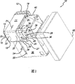
图1是柔性传送实体成像系统的正面透视图,其中该系统使用辐射透明柔性环形带作为构建材料转移装置并使用定轨与张紧装置;Figure 1 is a front perspective view of a flexible transport entity imaging system using a radiation transparent flexible endless belt as a build material transfer device and using rail positioning and tensioning devices;
图2是柔性传送实体成像系统的局部分解正面透视图,示出了辐射透明柔性环形带以及定轨与张紧装置;Figure 2 is a partially exploded front perspective view of the flexible transport entity imaging system, showing the radiation transparent flexible endless belt and the rail positioning and tensioning device;
图3是柔性传送实体成像系统的后透视图,示出了辐射透明柔性环形带、光投射仪和构建材料供给料筒;3 is a rear perspective view of the flexible transport entity imaging system, showing the radiation transparent flexible endless belt, light projector, and build material supply cartridge;
图4是柔性传送实体成像系统的正视图;Fig. 4 is the front view of the imaging system of the flexible delivery entity;
图5是柔性传送实体成像系统及用于升降支撑台的一个步进电机的正面透视图,其中可固化液体构建材料从辐射透明柔性环形带转移至支撑台以在支撑台上形成三维目标;5 is a front perspective view of a flexible transport solid imaging system and a stepper motor for raising and lowering a support table in which a curable liquid build material is transferred from a radiation transparent flexible endless belt to the support table to form a three-dimensional object on the support table;
图6是柔性环形带定轨和感测系统的俯视图;以及Figure 6 is a top view of the flexible endless belt orbiting and sensing system; and
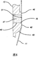
图7是柔性环形带定轨系统的一部分的视图,该系统在带沿着绕柔性传送实体成像系统的路径行进时控制带的定轨。7 is a view of a portion of a flexible endless belt orbiting system that controls the orbiting of the belt as it travels along a path around the flexible transport solid imaging system.
具体实施方式Detailed ways
本文公开的柔性传送实体成像包括使用适当的电光辐射源,以便从辐射可固化的液体光聚合物材料来分层构建制品,其中液体光聚合物材料由柔性环形传送带或往复式膜片输送。辐射源可使用有利于从电磁光谱反射的任何波长的辐射,例如具有电子或粒子束的光阀技术,但是优选使用可见光辐射或UV辐射。利用适当的覆层装置,例如影印轮(gravure wheel)或流体楔(fluid wedge),将液体光聚合物材料从料筒涂覆到柔性环形带或往复式膜片上,该覆层装置将光聚合物构建材料转移到柔性传送装置,以便在构建三维目标时,提供新的材料来产生新的层。光聚合物构建材料通过转移装置转移至接收基底,而不会在转移层中产生气泡。优选地,通过从数字UV投射仪或数字可见光投射仪射出的辐射而使光聚合物构建材料成像,并分层固化。投射仪包括空间光调制器,例如选择性地照明像素以便成像的数字微镜装置(“DMD”)。可见光投射是一种优选的方法。Flexible transfer entity imaging as disclosed herein involves the use of suitable electro-optic radiation sources to layer-build articles from radiation-curable liquid photopolymer materials conveyed by flexible endless conveyor belts or reciprocating membranes. The radiation source may use radiation of any wavelength that favors reflection from the electromagnetic spectrum, eg light valve technology with electrons or particle beams, but preferably uses visible radiation or UV radiation. The liquid photopolymer material is applied from a barrel onto a flexible endless belt or reciprocating diaphragm using a suitable coating device, such as a gravure wheel or a fluid wedge, which transfers the light The polymeric build material is transferred to the flexible delivery device to provide new material to create new layers as the 3D object is built. The photopolymer build material is transferred to the receiving substrate by the transfer device without creating air bubbles in the transfer layer. Preferably, the photopolymer build material is imaged and cured in layers by radiation emitted from a digital UV projector or a digital visible light projector. The projector includes a spatial light modulator, such as a digital micromirror device ("DMD") that selectively illuminates pixels for imaging. Visible light projection is a preferred method.
优选地,实体成像部件建在升降台上,在构建工艺过程中形成各连续层或薄层时,该升降台将所构建目标或部件向上移动与液体光聚合物构建材料相接触,并在曝光之后将所构建目标或部件向下移而与液体光聚合物构建材料脱离接触。所构建目标可以构建在已知为支撑件的结构上,而不是直接构建在升降台上。支撑件用于构建具有不可支撑或部分不可支撑表面的更复杂的三维目标。Preferably, the solid imaging part is built on a lift table that moves the built object or part up into contact with the liquid photopolymer build material as each successive layer or layer is formed during the build process, and during exposure The built object or part is then moved down out of contact with the liquid photopolymer build material. The built objects can be built on structures known as supports rather than directly on lift tables. Supports are used to construct more complex 3D objects with unsupportable or partially unsupportable surfaces.
可使用可商业购得的数字光投射仪(可选地可改动成具有较短焦距),例如可从InFocus Corporation of Wilson ville,Oregon和BenQAmerica Corp.of Irvine,California获得的数字光投射仪。Commercially available digital light projectors (optionally modified to have shorter focal lengths), such as those available from InFocus Corporation of Wilsonville, Oregon and BenQ America Corp. of Irvine, California, can be used.
在本发明的一个应用中,光聚合物构建材料经由对辐射透明的柔性构建材料承载膜(例如,聚丙烯或聚碳酸酯)输送到成像区域。在图1所示的实施例中,光聚合物构建材料以薄层的形式涂覆到柔性构建材料承载或传送膜上。In one application of the invention, a photopolymer build material is delivered to the imaging area via a radiation transparent flexible build material carrier film (eg, polypropylene or polycarbonate). In the embodiment shown in Figure 1, the photopolymer build material is applied in a thin layer to a flexible build material carrier or transport film.
如图1中所示,去除了盖子的柔性传送成像系统总体由标号10表示。柔性传送成像系统10具有形式为环形带11的对辐射透明的构建材料承载件,该环形带11绕驱动辊14、15和从动辊或惰辊19、20定位。构建材料供给料筒组件总体由标号12表示。料筒组件12和惰辊14、15固定在其相对位置上。带11由分别驱动辊14、15的驱动电机22、24沿箭头21所示的方向驱动。驱动辊14与驱动辊15之间的垂直距离是固定的,但是驱动辊14、15与惰辊19、20之间的水平距离是可变的,以便控制环形带11的张力。如图3中所示,惰辊19、20可旋转地安装在垂直机架组件17、23之间。As shown in FIG. 1 , the flexible transport imaging system with the cover removed is generally indicated at 10 . The flexible
见图3,数字光投射仪是辐射源44,在对支撑台53上形成的三维目标的横截面进行曝光时,该辐射源44将具有选择来照射的像素的图像投射在处于环形带11上侧运行部的下方的镜系统41上,这在图4中更加清楚地示出。如图5中实施例所示,支撑台53通过步进电机58升降。在图1-4的实施例中,使用一对步进电机58来将螺纹丝杠59以及在成像系统10相对两侧的导轨60向上驱动。通过适当紧固在系统机架上的导轨锚板61和62,将导轨60保持在适当的位置中。支撑台装配杆54被紧固到各个步进电机58。See Fig. 3, the digital light projector is a
如图1-4中所清楚示出的,支撑台装配杆54延伸穿过分别在机架端板35、45内的槽55、56。这使支撑台装配杆54能够通过步进电机58移动,以升降支撑台53。这使已形成的横截面层与从树脂或可固化液体介质料筒分配器13沉积在环形带11上的树脂或可固化液体构建材料层47相接触,该料筒分配器13是构建材料供给料筒组件12的一部分。简要参见图8,料筒分配器13包括可固化液体介质的树脂容器以及分配口或分配通道45,可固化液体构建材料通过该分配口或分配通道45涂覆到带11上。As best shown in FIGS. 1-4 , support
图1和2示出了总体由标号27表示的驱动辊支架。驱动辊14、15可旋转地安装在垂直机架组件16、18之间。驱动电机22、24安装到垂直机架组件18上,并驱动地连接到驱动辊14、15上。驱动辊垂直机架组件25附装到驱动电机的末端。带定轨电机26在带11绕着辊14、15、19和20旋转时控制带11的定轨,并且反向与驱动电机22和24相对。如图2中清楚所示,电机轴28从电机26延伸穿过机架组件25。带定轨控制臂29附装到轴28的末端。定轨控制臂机架组件30连接机架组件16和18,并包括用来安装驱动辊支架27的枢轴附件31(如图4和6简要所示)。如图1和2中所示,在机架组件30上安装有左边缘带定轨光学传感器33和右边缘带定轨光学传感器37。1 and 2 show a drive roller support generally indicated at 27 .
图6是驱动辊支架27的俯视示意图。连同垂直机架组件16、18和25一起示出了驱动辊14、惰辊19和环形带11(以虚线的形式)。驱动辊支架上的枢轴附件31与机架端板35上的枢轴39之间附装有安装臂36。枢轴附件31的枢轴点从附件31的中心偏移一小段距离。气缸32安装成穿过端板35,使得缸塞34与图1和2中定轨控制臂机架组件30背面上的枢轴附件31的背部相接触。当给图6的气缸32增压时,缸塞34通过枢轴附件31在驱动辊支架上施加力。整个驱动辊支架绕着枢轴39运动,该运动使驱动辊14、15与惰轮19、20之间的距离伸长,由此当缸塞34伸出时在环形带11上施加张力,或者当缸塞34缩回时缩短该距离从而减小张力。这样,可在环形带11上保持所需的张力。FIG. 6 is a schematic top view of the driving
如图8中所示,当带11垂直向下行进通过构建材料料筒分配器13中的分配口或分配通道45时,带11中的张力控制着涂覆到环形带11的可固化液体构建材料47的厚度。分配口或分配通道45从料筒分配器13之中的容器(未示出)向带11的表面51供应材料。料筒分配器13具有分别位于通道45上方和下方的平坦部分46和48,并且在底部具有大半径弧形部分49,以便在带被沿其路径绕着辊14、15、19和20驱动时,对带11的覆层表面51上的构建材料47提供间隙。可选择地,部分49可成锐角或直角,以提供所需的间隙。当带11运动通过通道45时,在通道45的底边50产生流体楔,通过流体楔效应在带11上涂覆均匀的覆层,使得张力越大,覆层就越薄。料筒分配器13可具有与其一体或与其远离的液体构建材料47的容器。如果与分配器13远离,则该容器与分配器13流体连通,使得该容器可与料筒分配器13分开更换。As shown in Figure 8, as the
覆层厚度由适当的传感器监测,如图案识别装置。如果覆层厚度太厚,则缸塞34将缓慢地伸出,以提高带11的张力并减小流体楔,从而使覆层变薄,直到得到正确厚度的覆层。或者,如果覆层太薄,则缸塞34将缩回,以降低带11的张力并从而增大流体楔,使覆层变厚直到达到所需的厚度。覆层厚度可控制到0.002英寸以用于较快的成像,或者可控制到0.001英寸以用于较慢的成像。气缸32可以对带11施加每平方英寸10至20磅之间的力,以确保带被绕着辊14、15、19和20张紧。还可使用任意其它有效装置来在带11上施加压力,例如电磁阀、弹簧或其它适当的机械系统。无论通道45具有倾斜底边50还是直的或圆的底表面,都可有效地产生流体楔。流体楔的效率随着很多因素的变化而变化,这些因素包括:可固化液体构建材料47的粘度、构建材料47与带11之间的表面张力、料筒分配器13中液体构建材料47的压头(pressure head)、分配通道45的开口的高度、平坦部分46和48的长度、以及带11在绕着辊14、15、19和20运行经过通道50时带11的速度和张力。The coating thickness is monitored by suitable sensors, such as pattern recognition devices. If the coating thickness is too thick, the
现在参见图6和图7,带定轨电机26在定轨控制臂29上施加旋转力。控制臂29经由任何适于使驱动辊支架27枢转的连接件(例如磁球38)而附装到安装臂36例如。球38位于控制臂29的槽和安装臂36的埋头孔内。如果电机22施加顺时针的旋转力,则控制臂29将磁球38推入安装臂36,迫使驱动辊支架27离开安装臂36。相反,如果电机22施加逆时针的旋转力,则控制臂29远离安装臂36,磁力将支架推向安装臂36。这使驱动辊支架绕着图6的枢轴点31旋转。因此,驱动辊14和15旋转以转动带11。如图1和图2中所示,如果驱动辊支架27顺时针旋转,则带11左转,而驱动辊支架27逆时针旋转时,带11右转。再参见图2,定轨传感器33和37相距一段距离,使得带11的宽度刚好分别在传感器33和37的边缘上方延伸。传感器33和37为感测带11的存在的光学传感器。在操作中,当驱动带11时,带11将横向平移,直到其露出传感器33或37之一。然后,定轨电机22上的力将反向,并且带11将平移,直到露出另一个传感器,该过程再次反向。这样,带11不断地在一小段距离中横向地来回移动。Referring now to FIGS. 6 and 7 , the
在辐射光源44与覆有可固化液体构建材料47的带11上的对象区域之间设有适当的副像素图像位移装置(未示出)。通过照射所选像素来曝光图像横截面而产生要形成的三维目标的横截面的固化部分。可选择地,副像素图像位移装置可以是具有位于环形带11运行部之外的像素移位装置的镜子,或者副像素图像位移装置可在单个组件中组合有镜子和像素移位装置。Suitable sub-pixel image displacement means (not shown) are provided between the
在本发明的实施中,可使用能够响应于施加适当形式的能量激励而固化的任何适当的流体构建材料。已知许多种可通过用UV辐射或可见光照射而变为固态聚合塑料的液态化学物质。在下面的表格I中示出了在实施本发明中可以使用的适合的可见光可固化的光聚合物。当使用BenQ PB7220投射仪时,该配方展示出优异的分辨率和感光速度。所产生的部件显示出具有平衡硬度和韧性的突出的生坯强度(green strength)。In the practice of the present invention, any suitable fluid build material capable of curing in response to application of an appropriate form of energy stimulus may be used. Many liquid chemicals are known which can be changed to solid polymeric plastics by irradiation with UV radiation or visible light. Suitable visible light curable photopolymers that may be used in the practice of the present invention are shown in Table I below. This formulation exhibits excellent resolution and photospeed when using a BenQ PB7220 projector. The resulting parts exhibit outstanding green strength with balanced hardness and toughness.
表I
可向配方中加入添加剂以提高从透明传送装置分离的能力,这些添加剂例如硅丙烯酸脂材料。Additives, such as silicone acrylate materials, may be added to the formulation to enhance the ability to separate from the transparent transport.
在操作中,构建三维目标的数据从CAD站(未示出)发送到柔性传送实体成像系统,该CAD站将CAD数据转换成适当的数字层数据格式并将其输入到计算机控制系统(也未示出),在该计算机控制系统中,通过算法操纵目标数据来优化数据以给数字光投射仪提供开启/关闭指令。通过由产生横截面数据的切片程序处理的CAD数据得到实体成像层数据。然后,通过适当的控制器,例如微处理器或计算机,对横截面数据应用算法以对数字光投射仪提供指令,以便照射所形成横截面中位于三维目标边界内的图像中的所选像素。可使用适当的像素移位图像位移装置,以提高所生成横截面的分辨率和边缘平滑度。In operation, data to construct a three-dimensional object is sent to the flexible transport solid imaging system from a CAD station (not shown), which converts the CAD data into an appropriate digital layer data format and inputs it to a computer control system (also not shown). shown), in the computer control system, the target data is manipulated by an algorithm to optimize the data to provide an on/off command to the digital light projector. Solid imaging layer data is obtained from CAD data processed by a slicing program that generates cross-sectional data. Algorithms are then applied to the cross-sectional data by a suitable controller, such as a microprocessor or computer, to provide instructions to the digital light projector to illuminate selected pixels in the image of the resulting cross-section that lie within the boundaries of the three-dimensional object. Appropriate pixel-shifting image displacement devices can be used to increase the resolution and edge smoothness of the generated cross-sections.
在完成层的成像后,降低支撑台53。由于固化图像现在粘在带11与支撑台53上,所以带11被支撑台53向下拉成弓形,直到将部件层从带11剥离。然后带11返回其伸直的状态。承载构建材料47的辐射透明带11从形成待形成三维部件横截面的构建材料的暴露固化层剥离,且其间不会有水平运动。辐射透明带11的柔性使得分离能够以剥离作用的形式发生,因为分离力与构建材料47的曝光区域的宽度成比例而与曝光构建材料的总面积成反比,如同在非柔性平面的情形中所发生的那样。After the imaging of the layers is completed, the support table 53 is lowered. Since the cured image is now stuck to the
选择部件在构建支撑台53上构建的基底,以使该部分对该基底的粘合强度大于其对带11的粘合强度。基底材料应当是透光的、柔性的,并且易于附装到构建支撑台53上。其可为细砂纸或类似的材料以提供握持性,但是更优选地是多孔材料,例如硅树脂粉(ground silicone),该多孔材料允许所有湿的未固化材料从部件流走以使部件尽可能保持干燥。The substrate on which the part is built on the build support table 53 is chosen such that the bond strength of the part to the substrate is greater than its bond strength to the
随着部件的增大,各新层粘合到位于其下方的固化构建材料层上。一旦支撑台处于其最低位置,就沿行进方向21驱动带来用构建材料47重新涂覆带11。为建立层厚一致的构建材料,带11将被驱动约12”至18”。然后支撑台53上升至适当的位置。由于现在在支撑台53上具有0.001”厚的部件切片,所以支撑台53升入比前一个低0.001”的位置,使得现在部件顶部与带11的表面51上的构建材料47的覆层紧密接触。实际上,由步进电机58来控制该定位,该步进电机58以非常精确的运动并且可重复的方式升降支撑台53。例如,如果在每次曝光之后电机58将支撑台向下移0.500”,但只向上移0.499”,则它们将总是补偿每次循环所产生的0.001”。既然带11已经被重新涂覆并且支撑台53处于适当的位置,于是就投射部件的下一切片,并且该过程继续直到完成部件。As the part grows, each new layer is bonded to the underlying layer of cured build material. Once the support table is in its lowest position, the belt is driven in the direction of
尽管已经参考其具体实施例描述了本发明,但是应当清楚,在不脱离这里公开的本发明概念的情况下,可在材料、各部分的布置及步骤上做出许多变化、修改和变动。例如,在使用激光器、激光扫描镜和其它相关的设备来替代数字图像投射设备的情况下,不使用副像素图像位移装置。在构建过程中使用支撑件的情况下,采用两种不同的材料或一种与构建目标和支撑件相同的材料。Although the invention has been described with reference to specific embodiments thereof, it should be apparent that many changes, modifications and variations in materials, arrangement of parts and steps may be made without departing from the inventive concepts disclosed herein. For example, in cases where lasers, laser scanning mirrors and other related equipment are used instead of digital image projection equipment, sub-pixel image displacement means are not used. Where supports are used in the build process, use two different materials or one material that is the same as the build target and support.
因此,所附权利要求的精神和范围希望覆盖所有这些本领域技术人员通过阅读本公开后可做出的变化、修改和变动。本文所引用的所有专利申请、专利和其它公开文献都通过参考而整体包含于此。Therefore, the spirit and scope of the appended claims are intended to cover all such changes, modifications and alterations that may occur to those skilled in the art from the reading of this disclosure. All patent applications, patents, and other publications cited herein are hereby incorporated by reference in their entirety.
Claims (10)
Applications Claiming Priority (2)
| Application Number | Priority Date | Filing Date | Title |
|---|---|---|---|
| US11/416,812 US7467939B2 (en) | 2006-05-03 | 2006-05-03 | Material delivery tension and tracking system for use in solid imaging |
| US11/416,812 | 2006-05-03 |
Publications (2)
| Publication Number | Publication Date |
|---|---|
| CN101067720A true CN101067720A (en) | 2007-11-07 |
| CN101067720B CN101067720B (en) | 2012-11-07 |
Family
ID=38421621
Family Applications (1)
| Application Number | Title | Priority Date | Filing Date |
|---|---|---|---|
| CN2007101011291A Expired - Fee Related CN101067720B (en) | 2006-05-03 | 2007-04-29 | Solid imaging system |
Country Status (4)
| Country | Link |
|---|---|
| US (2) | US7467939B2 (en) |
| EP (1) | EP1852243B1 (en) |
| JP (1) | JP4787204B2 (en) |
| CN (1) | CN101067720B (en) |
Cited By (4)
| Publication number | Priority date | Publication date | Assignee | Title |
|---|---|---|---|---|
| CN102666073A (en) * | 2009-12-17 | 2012-09-12 | 帝斯曼知识产权资产管理有限公司 | Substrate-based additive fabrication process |
| CN105209240A (en) * | 2013-03-12 | 2015-12-30 | 橙色制造者有限责任公司 | 3d printing using spiral buildup |
| CN108602123A (en) * | 2016-01-28 | 2018-09-28 | 西门子股份公司 | Method and apparatus for checking the component for wanting increasing material manufacturing |
| US10150247B2 (en) | 2013-03-12 | 2018-12-11 | Orange Maker LLC | 3D printing using spiral buildup and high viscosity build materials |
Families Citing this family (52)
| Publication number | Priority date | Publication date | Assignee | Title |
|---|---|---|---|---|
| DE102004022606A1 (en) | 2004-05-07 | 2005-12-15 | Envisiontec Gmbh | Method for producing a three-dimensional object with improved separation of hardened material layers from a building level |
| EP1744871B1 (en) | 2004-05-10 | 2008-05-07 | Envisiontec GmbH | Method for producing a three-dimensional object with resolution enhancement by means of pixel shift |
| DE102004022961B4 (en) | 2004-05-10 | 2008-11-20 | Envisiontec Gmbh | Method for producing a three-dimensional object with resolution improvement by means of pixel shift |
| DE102006019963B4 (en) | 2006-04-28 | 2023-12-07 | Envisiontec Gmbh | Device and method for producing a three-dimensional object by layer-by-layer solidifying a material that can be solidified under the influence of electromagnetic radiation using mask exposure |
| DE102006019964C5 (en) | 2006-04-28 | 2021-08-26 | Envisiontec Gmbh | Device and method for producing a three-dimensional object by means of mask exposure |
| US7931460B2 (en) * | 2006-05-03 | 2011-04-26 | 3D Systems, Inc. | Material delivery system for use in solid imaging |
| US7467939B2 (en) * | 2006-05-03 | 2008-12-23 | 3D Systems, Inc. | Material delivery tension and tracking system for use in solid imaging |
| BRPI0602943B1 (en) * | 2006-06-30 | 2017-05-23 | Brudden Equip | treadmill belt misalignment flag |
| EP1876012A1 (en) | 2006-07-07 | 2008-01-09 | Nederlandse Organisatie voor Toegepast-Natuuurwetenschappelijk Onderzoek TNO | System and method for producing a tangible object |
| US7636610B2 (en) * | 2006-07-19 | 2009-12-22 | Envisiontec Gmbh | Method and device for producing a three-dimensional object, and computer and data carrier useful therefor |
| US9415544B2 (en) * | 2006-08-29 | 2016-08-16 | 3D Systems, Inc. | Wall smoothness, feature accuracy and resolution in projected images via exposure levels in solid imaging |
| US7892474B2 (en) | 2006-11-15 | 2011-02-22 | Envisiontec Gmbh | Continuous generative process for producing a three-dimensional object |
| US7771183B2 (en) * | 2007-01-17 | 2010-08-10 | 3D Systems, Inc. | Solid imaging system with removal of excess uncured build material |
| US8105066B2 (en) * | 2007-01-17 | 2012-01-31 | 3D Systems, Inc. | Cartridge for solid imaging apparatus and method |
| US8221671B2 (en) * | 2007-01-17 | 2012-07-17 | 3D Systems, Inc. | Imager and method for consistent repeatable alignment in a solid imaging apparatus |
| US8003039B2 (en) * | 2007-01-17 | 2011-08-23 | 3D Systems, Inc. | Method for tilting solid image build platform for reducing air entrainment and for build release |
| US7731887B2 (en) * | 2007-01-17 | 2010-06-08 | 3D Systems, Inc. | Method for removing excess uncured build material in solid imaging |
| US20080181977A1 (en) * | 2007-01-17 | 2008-07-31 | Sperry Charles R | Brush assembly for removal of excess uncured build material |
| US7706910B2 (en) * | 2007-01-17 | 2010-04-27 | 3D Systems, Inc. | Imager assembly and method for solid imaging |
| US20080226346A1 (en) * | 2007-01-17 | 2008-09-18 | 3D Systems, Inc. | Inkjet Solid Imaging System and Method for Solid Imaging |
| US7614866B2 (en) * | 2007-01-17 | 2009-11-10 | 3D Systems, Inc. | Solid imaging apparatus and method |
| US20080170112A1 (en) * | 2007-01-17 | 2008-07-17 | Hull Charles W | Build pad, solid image build, and method for building build supports |
| WO2008103985A2 (en) * | 2007-02-23 | 2008-08-28 | The Exone Company, Llc | Replaceable build box for three dimensional printer |
| EP2011631B1 (en) | 2007-07-04 | 2012-04-18 | Envisiontec GmbH | Process and device for producing a three-dimensional object |
| EP2481555B1 (en) | 2007-09-17 | 2021-08-25 | 3D Systems, Inc. | Region-based supports for parts produced by solid freeform fabrication |
| EP2052693B2 (en) | 2007-10-26 | 2021-02-17 | Envisiontec GmbH | Process and freeform fabrication system for producing a three-dimensional object |
| US20100056661A1 (en) * | 2008-09-03 | 2010-03-04 | Pingyong Xu | Radiation Curable Compositions Useful in Image Projection Systems |
| US8048359B2 (en) | 2008-10-20 | 2011-11-01 | 3D Systems, Inc. | Compensation of actinic radiation intensity profiles for three-dimensional modelers |
| US8777602B2 (en) | 2008-12-22 | 2014-07-15 | Nederlandse Organisatie Voor Tobgepast-Natuurwetenschappelijk Onderzoek TNO | Method and apparatus for layerwise production of a 3D object |
| JP5873720B2 (en) | 2008-12-22 | 2016-03-01 | ネーデルランデ オルガニサチエ ヴォール トエゲパスト−ナツールウェテンスハペリエク オンデルゾエク ティーエヌオーNederlandse Organisatie Voor Toegepast−Natuurwetenschappelijk Onderzoek Tno | Method and system for layered manufacturing of 3D tangible objects |
| US8678805B2 (en) | 2008-12-22 | 2014-03-25 | Dsm Ip Assets Bv | System and method for layerwise production of a tangible object |
| US8372330B2 (en) | 2009-10-19 | 2013-02-12 | Global Filtration Systems | Resin solidification substrate and assembly |
| ES2449291T3 (en) | 2010-11-01 | 2014-03-19 | Dsm Ip Assets B.V. | Apparatus and method of manufacturing by addition comprising an alternative motion sheet guide system |
| EP2646223B1 (en) * | 2010-11-29 | 2017-06-28 | 3D Systems, Inc. | Stereolithography systems and methods using internal laser modulation |
| US8691476B2 (en) | 2011-12-16 | 2014-04-08 | Taiwan Semiconductor Manufacturing Company, Ltd. | EUV mask and method for forming the same |
| ITVI20120183A1 (en) * | 2012-07-27 | 2014-01-28 | Dws Srl | CARTRIDGE FOR STEREOLITHOGRAPHIC MACHINE, STEREOLITHOGRAPHIC MACHINE INCLUDING SUCH CARTRIDGE AND METHOD OF PRODUCTION OF SUCH CARTRIDGE |
| US9034237B2 (en) | 2012-09-25 | 2015-05-19 | 3D Systems, Inc. | Solid imaging systems, components thereof, and methods of solid imaging |
| WO2014141272A2 (en) * | 2013-03-14 | 2014-09-18 | Stratasys Ltd. | Enhanced resolution dlp projector apparatus and method of using same |
| EP3089862B1 (en) | 2014-01-02 | 2021-03-17 | United Technologies Corporation | Additive manufacturing process distortion management |
| US9527244B2 (en) | 2014-02-10 | 2016-12-27 | Global Filtration Systems | Apparatus and method for forming three-dimensional objects from solidifiable paste |
| CN103802322B (en) * | 2014-03-07 | 2015-12-09 | 济南大学 | New 3D printer based on FDM |
| CN103878977B (en) * | 2014-03-07 | 2016-03-02 | 济南大学 | The 3D printer of a kind of FDM |
| RU2609911C2 (en) * | 2014-11-06 | 2017-02-07 | Вячеслав Рубинович Шулунов | Method for manufacturing items by roll powder sintering |
| US10792868B2 (en) | 2015-09-09 | 2020-10-06 | Carbon, Inc. | Method and apparatus for three-dimensional fabrication |
| CN106824671B (en) * | 2016-12-28 | 2019-03-12 | 兰州空间技术物理研究所 | A tool and method suitable for coating blackbody absorbing material of spaceborne calibration source |
| US10737479B2 (en) | 2017-01-12 | 2020-08-11 | Global Filtration Systems | Method of making three-dimensional objects using both continuous and discontinuous solidification |
| RU2659049C1 (en) * | 2017-05-03 | 2018-06-27 | Вячеслав Рубинович Шулунов | Method of the product manufacturing by the roll powder sintering |
| US11919246B2 (en) | 2017-07-11 | 2024-03-05 | Daniel S. Clark | 5D part growing machine with volumetric display technology |
| US10967578B2 (en) | 2017-07-11 | 2021-04-06 | Daniel S. Clark | 5D part growing machine with volumetric display technology |
| US10639852B2 (en) * | 2017-09-07 | 2020-05-05 | Xyzprinting, Inc. | Stereolithography 3D printer |
| US12121964B2 (en) | 2018-11-07 | 2024-10-22 | James J. Myrick | Processes, compositions and systems for 2D and 3D printing |
| US11964430B2 (en) | 2020-09-17 | 2024-04-23 | Concept Laser Gmbh | Controlling irradiation parameters of an additive manufacturing machine |
Citations (4)
| Publication number | Priority date | Publication date | Assignee | Title |
|---|---|---|---|---|
| US5186313A (en) * | 1992-05-06 | 1993-02-16 | Doboy Packaging Machinery, Inc. | Conveyor belt tracking and drive mechanism |
| DE19957379A1 (en) * | 1998-11-27 | 2000-06-21 | Usui Kokusai Sangyo Kk | EGR cooler |
| CN1441321A (en) * | 2002-02-27 | 2003-09-10 | 三菱化学工程株式会社 | Development liquid supply device |
| US20050019499A1 (en) * | 2001-10-29 | 2005-01-27 | Fuji Photo Film Co., Ltd. | Coating method and apparatus |
Family Cites Families (70)
| Publication number | Priority date | Publication date | Assignee | Title |
|---|---|---|---|---|
| US4752498A (en) | 1987-03-02 | 1988-06-21 | Fudim Efrem V | Method and apparatus for production of three-dimensional objects by photosolidification |
| US5287435A (en) * | 1987-06-02 | 1994-02-15 | Cubital Ltd. | Three dimensional modeling |
| US5876550A (en) * | 1988-10-05 | 1999-03-02 | Helisys, Inc. | Laminated object manufacturing apparatus and method |
| US5171490A (en) | 1988-11-29 | 1992-12-15 | Fudim Efrem V | Method and apparatus for production of three-dimensional objects by irradiation of photopolymers |
| US5014207A (en) | 1989-04-21 | 1991-05-07 | E. I. Du Pont De Nemours And Company | Solid imaging system |
| JPH03244528A (en) | 1989-09-28 | 1991-10-31 | Three D Syst Inc | Device and method forming substantially flat and solid face for processing planograph |
| US5143817A (en) | 1989-12-22 | 1992-09-01 | E. I. Du Pont De Nemours And Company | Solid imaging system |
| US5236812A (en) | 1989-12-29 | 1993-08-17 | E. I. Du Pont De Nemours And Company | Solid imaging method and apparatus |
| US5626919A (en) | 1990-03-01 | 1997-05-06 | E. I. Du Pont De Nemours And Company | Solid imaging apparatus and method with coating station |
| US5094935A (en) | 1990-06-26 | 1992-03-10 | E. I. Dupont De Nemours And Company | Method and apparatus for fabricating three dimensional objects from photoformed precursor sheets |
| US5096530A (en) | 1990-06-28 | 1992-03-17 | 3D Systems, Inc. | Resin film recoating method and apparatus |
| US5049901A (en) | 1990-07-02 | 1991-09-17 | Creo Products Inc. | Light modulator using large area light sources |
| US5158858A (en) | 1990-07-05 | 1992-10-27 | E. I. Du Pont De Nemours And Company | Solid imaging system using differential tension elastomeric film |
| US5192559A (en) | 1990-09-27 | 1993-03-09 | 3D Systems, Inc. | Apparatus for building three-dimensional objects with sheets |
| US5122441A (en) | 1990-10-29 | 1992-06-16 | E. I. Du Pont De Nemours And Company | Method for fabricating an integral three-dimensional object from layers of a photoformable composition |
| US5474719A (en) | 1991-02-14 | 1995-12-12 | E. I. Du Pont De Nemours And Company | Method for forming solid objects utilizing viscosity reducible compositions |
| US5132723A (en) | 1991-09-05 | 1992-07-21 | Creo Products, Inc. | Method and apparatus for exposure control in light valves |
| US5252264A (en) * | 1991-11-08 | 1993-10-12 | Dtm Corporation | Apparatus and method for producing parts with multi-directional powder delivery |
| US5247180A (en) | 1991-12-30 | 1993-09-21 | Texas Instruments Incorporated | Stereolithographic apparatus and method of use |
| JPH0784033B2 (en) * | 1992-02-20 | 1995-09-13 | 帝人製機株式会社 | Stereolithography apparatus and stereolithography method |
| US5306446A (en) | 1992-07-10 | 1994-04-26 | Howe Robert J | Apparatus with roller and for irradiation of photopolymers |
| US5429908A (en) | 1993-04-12 | 1995-07-04 | E. I. Du Pont De Nemours And Company | Exposure method for reducing distortion in models produced through solid imaging by forming a non-continuous image of a pattern which is then imaged to form a continuous hardened image of the pattern |
| JP2706611B2 (en) | 1993-10-14 | 1998-01-28 | 帝人製機株式会社 | Stereolithography method and stereolithography device |
| US6206672B1 (en) * | 1994-03-31 | 2001-03-27 | Edward P. Grenda | Apparatus of fabricating 3 dimensional objects by means of electrophotography, ionography or a similar process |
| IL112140A (en) * | 1994-12-25 | 1997-07-13 | Cubital Ltd | Method of forming three dimensional objects |
| US5922364A (en) * | 1997-03-03 | 1999-07-13 | Young, Jr.; Albert C. | Stereolithography layering control system |
| US6051179A (en) | 1997-03-19 | 2000-04-18 | Replicator Systems, Inc. | Apparatus and method for production of three-dimensional models by spatial light modulator |
| US6066285A (en) * | 1997-12-12 | 2000-05-23 | University Of Florida | Solid freeform fabrication using power deposition |
| US6050915A (en) * | 1998-09-09 | 2000-04-18 | Walworth; Roger L. | Belt tensioner |
| EP1156922B8 (en) | 1998-10-12 | 2004-05-26 | Dicon A/S | Rapid prototyping apparatus and method of rapid prototyping |
| US6391245B1 (en) | 1999-04-13 | 2002-05-21 | Eom Technologies, L.L.C. | Method for creating three-dimensional objects by cross-sectional lithography |
| US6627376B1 (en) | 1999-04-27 | 2003-09-30 | Teijin Seiki Co., Ltd. | Stereolithographic apparatus and method for manufacturing three-dimensional object with photohardenable resin |
| US6214276B1 (en) | 1999-05-18 | 2001-04-10 | Creo Srl | Method of forming objects from thermosensitive composition |
| GB9919511D0 (en) | 1999-08-19 | 1999-10-20 | British Aerospace | Stereolithography |
| DE19939616C5 (en) | 1999-08-20 | 2008-05-21 | Eos Gmbh Electro Optical Systems | Device for the generative production of a three-dimensional object |
| DE19944760A1 (en) | 1999-09-17 | 2001-03-22 | Basys Print Gmbh Systeme Fuer | Device and method for compensating for inhomogeneities in imaging systems |
| DE19957370C2 (en) | 1999-11-29 | 2002-03-07 | Carl Johannes Fruth | Method and device for coating a substrate |
| US6547552B1 (en) | 2000-02-08 | 2003-04-15 | Efrem V. Fudim | Fabrication of three-dimensional objects by irradiation of radiation-curable materials |
| DE10018987A1 (en) | 2000-04-17 | 2001-10-31 | Envision Technologies Gmbh | Device and method for producing three-dimensional objects |
| US6500378B1 (en) * | 2000-07-13 | 2002-12-31 | Eom Technologies, L.L.C. | Method and apparatus for creating three-dimensional objects by cross-sectional lithography |
| US6571986B1 (en) * | 2000-10-18 | 2003-06-03 | Impaxx Machines Systems, Inc. | Quick change roll-fed high speed labeling system having a segmented construction |
| US6780368B2 (en) * | 2001-04-10 | 2004-08-24 | Nanotek Instruments, Inc. | Layer manufacturing of a multi-material or multi-color 3-D object using electrostatic imaging and lamination |
| DE20106887U1 (en) | 2001-04-20 | 2001-09-06 | Envision Technologies GmbH, 45768 Marl | Device for producing a three-dimensional object |
| DE10119817A1 (en) | 2001-04-23 | 2002-10-24 | Envision Technologies Gmbh | Separation layer between a flat baseplate and layers of cured polymer formed during fabrication of three-dimensional objects comprises a low adhesion film or a gel |
| DE10130968B4 (en) | 2001-06-27 | 2009-08-20 | Envisiontec Gmbh | Coated polymeric material, its use and process for its preparation |
| US6665048B2 (en) | 2002-01-22 | 2003-12-16 | Creo Inc. | Method for imaging a continuously moving object |
| DE10256672B4 (en) | 2002-12-04 | 2019-05-09 | Envisiontec Gmbh | Method for separating stereolithographically hardened material layers from a contact surface |
| DE10310385B4 (en) * | 2003-03-07 | 2006-09-21 | Daimlerchrysler Ag | Method for the production of three-dimensional bodies by means of powder-based layer-building methods |
| WO2004106041A2 (en) * | 2003-05-23 | 2004-12-09 | Z Corporation | Apparatus and methods for 3d printing |
| US7094484B2 (en) * | 2003-07-22 | 2006-08-22 | Fuji Photo Film Co., Ltd. | Master carrier for magnetic transfer, inspecting method thereof, and magnetic recording medium producing method |
| US7261542B2 (en) * | 2004-03-18 | 2007-08-28 | Desktop Factory, Inc. | Apparatus for three dimensional printing using image layers |
| DE102004022606A1 (en) | 2004-05-07 | 2005-12-15 | Envisiontec Gmbh | Method for producing a three-dimensional object with improved separation of hardened material layers from a building level |
| DE102004022961B4 (en) | 2004-05-10 | 2008-11-20 | Envisiontec Gmbh | Method for producing a three-dimensional object with resolution improvement by means of pixel shift |
| US7158849B2 (en) | 2004-10-28 | 2007-01-02 | National Cheng Kung University | Method for rapid prototyping by using linear light as sources |
| US20060192312A1 (en) * | 2005-02-28 | 2006-08-31 | 3D Systems, Inc. | Multiple vat leveling system |
| US7758799B2 (en) * | 2005-04-01 | 2010-07-20 | 3D Systems, Inc. | Edge smoothness with low resolution projected images for use in solid imaging |
| US7358283B2 (en) * | 2005-04-01 | 2008-04-15 | 3D Systems, Inc. | Radiation curable compositions useful in image projection systems |
| US7906061B2 (en) * | 2005-05-03 | 2011-03-15 | 3D Systems, Inc. | Bubble-free cross-sections for use in solid imaging |
| US7467939B2 (en) * | 2006-05-03 | 2008-12-23 | 3D Systems, Inc. | Material delivery tension and tracking system for use in solid imaging |
| US7931460B2 (en) | 2006-05-03 | 2011-04-26 | 3D Systems, Inc. | Material delivery system for use in solid imaging |
| US8003039B2 (en) * | 2007-01-17 | 2011-08-23 | 3D Systems, Inc. | Method for tilting solid image build platform for reducing air entrainment and for build release |
| US20080181977A1 (en) * | 2007-01-17 | 2008-07-31 | Sperry Charles R | Brush assembly for removal of excess uncured build material |
| US7706910B2 (en) * | 2007-01-17 | 2010-04-27 | 3D Systems, Inc. | Imager assembly and method for solid imaging |
| US7614866B2 (en) * | 2007-01-17 | 2009-11-10 | 3D Systems, Inc. | Solid imaging apparatus and method |
| US20080226346A1 (en) * | 2007-01-17 | 2008-09-18 | 3D Systems, Inc. | Inkjet Solid Imaging System and Method for Solid Imaging |
| US20080170112A1 (en) * | 2007-01-17 | 2008-07-17 | Hull Charles W | Build pad, solid image build, and method for building build supports |
| US8105066B2 (en) * | 2007-01-17 | 2012-01-31 | 3D Systems, Inc. | Cartridge for solid imaging apparatus and method |
| US8221671B2 (en) * | 2007-01-17 | 2012-07-17 | 3D Systems, Inc. | Imager and method for consistent repeatable alignment in a solid imaging apparatus |
| US7771183B2 (en) * | 2007-01-17 | 2010-08-10 | 3D Systems, Inc. | Solid imaging system with removal of excess uncured build material |
| US7731887B2 (en) * | 2007-01-17 | 2010-06-08 | 3D Systems, Inc. | Method for removing excess uncured build material in solid imaging |
-
2006
- 2006-05-03 US US11/416,812 patent/US7467939B2/en active Active
-
2007
- 2007-04-27 EP EP07251785A patent/EP1852243B1/en not_active Ceased
- 2007-04-29 CN CN2007101011291A patent/CN101067720B/en not_active Expired - Fee Related
- 2007-05-07 JP JP2007122293A patent/JP4787204B2/en not_active Expired - Fee Related
-
2008
- 2008-11-19 US US12/273,924 patent/US20090110763A1/en not_active Abandoned
Patent Citations (4)
| Publication number | Priority date | Publication date | Assignee | Title |
|---|---|---|---|---|
| US5186313A (en) * | 1992-05-06 | 1993-02-16 | Doboy Packaging Machinery, Inc. | Conveyor belt tracking and drive mechanism |
| DE19957379A1 (en) * | 1998-11-27 | 2000-06-21 | Usui Kokusai Sangyo Kk | EGR cooler |
| US20050019499A1 (en) * | 2001-10-29 | 2005-01-27 | Fuji Photo Film Co., Ltd. | Coating method and apparatus |
| CN1441321A (en) * | 2002-02-27 | 2003-09-10 | 三菱化学工程株式会社 | Development liquid supply device |
Cited By (7)
| Publication number | Priority date | Publication date | Assignee | Title |
|---|---|---|---|---|
| CN102666073A (en) * | 2009-12-17 | 2012-09-12 | 帝斯曼知识产权资产管理有限公司 | Substrate-based additive fabrication process |
| CN102666073B (en) * | 2009-12-17 | 2015-07-22 | 帝斯曼知识产权资产管理有限公司 | Substrate-based additive fabrication process |
| CN105209240A (en) * | 2013-03-12 | 2015-12-30 | 橙色制造者有限责任公司 | 3d printing using spiral buildup |
| US9937665B2 (en) | 2013-03-12 | 2018-04-10 | Orange Maker, Llc | 3D printing using spiral buildup |
| US10150247B2 (en) | 2013-03-12 | 2018-12-11 | Orange Maker LLC | 3D printing using spiral buildup and high viscosity build materials |
| CN108602123A (en) * | 2016-01-28 | 2018-09-28 | 西门子股份公司 | Method and apparatus for checking the component for wanting increasing material manufacturing |
| US11703481B2 (en) | 2016-01-28 | 2023-07-18 | Siemens Energy Global Gmbh & Co. | Method for checking a component to be produced in an additive manner, and device |
Also Published As
| Publication number | Publication date |
|---|---|
| EP1852243B1 (en) | 2011-10-19 |
| US20070259066A1 (en) | 2007-11-08 |
| US20090110763A1 (en) | 2009-04-30 |
| JP2007296853A (en) | 2007-11-15 |
| US7467939B2 (en) | 2008-12-23 |
| JP4787204B2 (en) | 2011-10-05 |
| EP1852243A3 (en) | 2010-06-09 |
| EP1852243A2 (en) | 2007-11-07 |
| CN101067720B (en) | 2012-11-07 |
Similar Documents
| Publication | Publication Date | Title |
|---|---|---|
| CN101067720B (en) | Solid imaging system | |
| CN101067721B (en) | Material delivery system for use in solid imaging | |
| JP7645266B2 (en) | Systems and methods for lithography-based additive manufacturing of three-dimensional (3D) structures | |
| EP1710625B1 (en) | Improved edge smoothness with low resolution projected images for use in solid imaging | |
| KR101155684B1 (en) | Rapid Layer upon layer form Stereolithography | |
| EP2143552A1 (en) | Bubble-free cross-sections for use in solid imaging | |
| US11654625B2 (en) | Apparatuses for additively manufacturing three-dimensional objects | |
| CN110869189B (en) | Method and device for producing three-dimensional molded bodies on the basis of lithography | |
| JP6058819B2 (en) | 3D object production | |
| CN103167946A (en) | Apparatus and method for making an object | |
| US11845222B2 (en) | Increasing throughput in additive manufacturing using a rotating build platform | |
| KR102288941B1 (en) | stereo lithography 3D printer by using multi-resin coated film | |
| US20250381735A1 (en) | Method for cleaning an additively manufactured part | |
| WO2025005899A1 (en) | Method for high-speed 3d printing of objects with a structured build surface using a liquid photopolymer and device for implementing same | |
| CN110856978A (en) | 3D printing system and 3D printing method |
Legal Events
| Date | Code | Title | Description |
|---|---|---|---|
| C06 | Publication | ||
| PB01 | Publication | ||
| C10 | Entry into substantive examination | ||
| SE01 | Entry into force of request for substantive examination | ||
| C14 | Grant of patent or utility model | ||
| GR01 | Patent grant | ||
| CF01 | Termination of patent right due to non-payment of annual fee |
Granted publication date: 20121107 |