CN101006376B - Fiber Optic Receptacle and Plug Assemblies with Alignment and Keying Mechanisms - Google Patents
Fiber Optic Receptacle and Plug Assemblies with Alignment and Keying Mechanisms Download PDFInfo
- Publication number
- CN101006376B CN101006376B CN2005800277028A CN200580027702A CN101006376B CN 101006376 B CN101006376 B CN 101006376B CN 2005800277028 A CN2005800277028 A CN 2005800277028A CN 200580027702 A CN200580027702 A CN 200580027702A CN 101006376 B CN101006376 B CN 101006376B
- Authority
- CN
- China
- Prior art keywords
- receptacle
- plug
- alignment
- fiber optic
- ferrule
- Prior art date
- Legal status (The legal status is an assumption and is not a legal conclusion. Google has not performed a legal analysis and makes no representation as to the accuracy of the status listed.)
- Expired - Lifetime
Links
Images


Classifications
-
- G—PHYSICS
- G02—OPTICS
- G02B—OPTICAL ELEMENTS, SYSTEMS OR APPARATUS
- G02B6/00—Light guides; Structural details of arrangements comprising light guides and other optical elements, e.g. couplings
- G02B6/24—Coupling light guides
- G02B6/36—Mechanical coupling means
- G02B6/38—Mechanical coupling means having fibre to fibre mating means
- G02B6/3807—Dismountable connectors, i.e. comprising plugs
- G02B6/381—Dismountable connectors, i.e. comprising plugs of the ferrule type, e.g. fibre ends embedded in ferrules, connecting a pair of fibres
- G02B6/3826—Dismountable connectors, i.e. comprising plugs of the ferrule type, e.g. fibre ends embedded in ferrules, connecting a pair of fibres characterised by form or shape
- G02B6/3831—Dismountable connectors, i.e. comprising plugs of the ferrule type, e.g. fibre ends embedded in ferrules, connecting a pair of fibres characterised by form or shape comprising a keying element on the plug or adapter, e.g. to forbid wrong connection
-
- G—PHYSICS
- G02—OPTICS
- G02B—OPTICAL ELEMENTS, SYSTEMS OR APPARATUS
- G02B6/00—Light guides; Structural details of arrangements comprising light guides and other optical elements, e.g. couplings
- G02B6/24—Coupling light guides
- G02B6/36—Mechanical coupling means
- G02B6/38—Mechanical coupling means having fibre to fibre mating means
- G02B6/3807—Dismountable connectors, i.e. comprising plugs
- G02B6/3833—Details of mounting fibres in ferrules; Assembly methods; Manufacture
- G02B6/3847—Details of mounting fibres in ferrules; Assembly methods; Manufacture with means preventing fibre end damage, e.g. recessed fibre surfaces
-
- G—PHYSICS
- G02—OPTICS
- G02B—OPTICAL ELEMENTS, SYSTEMS OR APPARATUS
- G02B6/00—Light guides; Structural details of arrangements comprising light guides and other optical elements, e.g. couplings
- G02B6/24—Coupling light guides
- G02B6/36—Mechanical coupling means
- G02B6/38—Mechanical coupling means having fibre to fibre mating means
- G02B6/3807—Dismountable connectors, i.e. comprising plugs
- G02B6/3887—Anchoring optical cables to connector housings, e.g. strain relief features
- G02B6/3888—Protection from over-extension or over-compression
-
- G—PHYSICS
- G02—OPTICS
- G02B—OPTICAL ELEMENTS, SYSTEMS OR APPARATUS
- G02B6/00—Light guides; Structural details of arrangements comprising light guides and other optical elements, e.g. couplings
- G02B6/24—Coupling light guides
- G02B6/36—Mechanical coupling means
- G02B6/38—Mechanical coupling means having fibre to fibre mating means
- G02B6/3807—Dismountable connectors, i.e. comprising plugs
- G02B6/389—Dismountable connectors, i.e. comprising plugs characterised by the method of fastening connecting plugs and sockets, e.g. screw- or nut-lock, snap-in, bayonet type
-
- G—PHYSICS
- G02—OPTICS
- G02B—OPTICAL ELEMENTS, SYSTEMS OR APPARATUS
- G02B6/00—Light guides; Structural details of arrangements comprising light guides and other optical elements, e.g. couplings
- G02B6/46—Processes or apparatus adapted for installing or repairing optical fibres or optical cables
- G02B6/50—Underground or underwater installation; Installation through tubing, conduits or ducts
- G02B6/54—Underground or underwater installation; Installation through tubing, conduits or ducts using mechanical means, e.g. pulling or pushing devices
- G02B6/545—Pulling eyes
-
- G—PHYSICS
- G02—OPTICS
- G02B—OPTICAL ELEMENTS, SYSTEMS OR APPARATUS
- G02B6/00—Light guides; Structural details of arrangements comprising light guides and other optical elements, e.g. couplings
- G02B6/24—Coupling light guides
- G02B6/36—Mechanical coupling means
- G02B6/38—Mechanical coupling means having fibre to fibre mating means
- G02B6/3807—Dismountable connectors, i.e. comprising plugs
- G02B6/3873—Connectors using guide surfaces for aligning ferrule ends, e.g. tubes, sleeves, V-grooves, rods, pins, balls
- G02B6/3874—Connectors using guide surfaces for aligning ferrule ends, e.g. tubes, sleeves, V-grooves, rods, pins, balls using tubes, sleeves to align ferrules
- G02B6/3878—Connectors using guide surfaces for aligning ferrule ends, e.g. tubes, sleeves, V-grooves, rods, pins, balls using tubes, sleeves to align ferrules comprising a plurality of ferrules, branching and break-out means
- G02B6/3879—Linking of individual connector plugs to an overconnector, e.g. using clamps, clips, common housings comprising several individual connector plugs
Landscapes
- Physics & Mathematics (AREA)
- General Physics & Mathematics (AREA)
- Optics & Photonics (AREA)
- Mechanical Coupling Of Light Guides (AREA)
- Switches Operated By Changes In Physical Conditions (AREA)
- Geophysics And Detection Of Objects (AREA)
Abstract
Description
本申请为2004年8月24日提交的名称为“光纤插座以及插头组件”的美国专利申请No.10/924,525的部分接续申请。This application is a continuation-in-part of US Patent Application Serial No. 10/924,525, filed August 24, 2004, entitled "Fiber Optic Receptacle and Plug Assemblies."
技术领域technical field
本发明通常涉及一种用于光纤互连的组件,更具体地是涉及一种在光线通信网络中用于光纤互连的具有对准和键合机构的光纤插座和插头组件。The present invention relates generally to an assembly for optical fiber interconnection, and more particularly to an optical fiber receptacle and plug assembly with alignment and bonding mechanism for optical fiber interconnection in an optical communication network.
背景技术Background technique
光纤越来越多地应用于包括声音、视频和数据传输的各种宽带应用之中。这样,光纤通信网络包括光纤与其它光纤在此处相互连接的多个互连点。光纤网络还包括多个连接终端,其示例包括但不限于,网络接入点(NAP)机柜、架空接头盒、地下接头盒(below grade closure)、基座、光纤网络终端(ONT)和网络接口设备(NID)。在特定示例中,连接终端包括通常贯穿该终端的外壁的连接器端口,其用于在配线缆线的端接光纤与一个或多个预连接器化的分支缆线的各光纤之间建立光学连接,其中扩展的配线缆线、系缆(tether cable)或支线缆线(branch cable),在此统称为“分支缆线(drop cable)”。连接终端用于向用户提供通信服务。在这方面,正在研发提供通常称为“FTTx”的“光纤到路边”(FTTC)、“光纤到楼”(FTTB)、“光纤到户”(FTTH)和“光纤到驻地”(FTTP)的光纤网络。Fiber optics are increasingly used in a variety of broadband applications including voice, video and data transmission. Thus, a fiber optic communication network includes a plurality of interconnection points at which optical fibers interconnect with other optical fibers. Fiber optic networks also include multiple connection terminals, examples of which include, but are not limited to, network access point (NAP) cabinets, overhead closures, below grade closures, pedestals, fiber optic network terminals (ONTs) and network interfaces device (NID). In particular examples, the connection terminal includes a connector port generally extending through the outer wall of the terminal for establishing a connection between the terminating optical fiber of the distribution cable and the optical fibers of one or more pre-connectorized drop cables. Optical connections, including extended distribution cables, tether cables, or branch cables, are collectively referred to herein as "drop cables." The connection terminal is used to provide communication services to users. In this regard, research and development is underway to provide "Fibre to the Curb" (FTTC), "Fiber to the Building" (FTTB), "Fiber to the Home" (FTTH) and "Fibre to the Premises" (FTTP) commonly referred to as "FTTx" fiber optic network.
传统的贯穿连接器终端外壁的连接器端口包括用于接纳诸如尾纤的连接器化的光纤,以在该连接终端中与例如熔接盘或保护管中的配线缆线的光纤进行光学连接的插座。目前,由于这些插座设置在其中的连接终端并未限制插座的大小,所以这些插座在尺寸上相对较大。并且,现有的插座包括用于限定内腔以接纳并对准配合套筒的插座外壳。如前所述,一个配合套管安装在与连接终端中的配线缆线的光纤进行光学连接的光纤的端部。另一配合套管安装在从该连接终端的外部延伸至插座中的分支缆线的光纤的端部。插座的对准套筒有助于套管的粗对准,并且套管导销或其它对准装置可有助于套管的相对端面的更精确的对准。Conventional connector ports extending through the outer wall of a connector terminal include means for receiving connectorized optical fibers, such as pigtails, for optical connection in the terminal with, for example, optical fibers of distribution cables in splice trays or protective tubes. socket. Currently, these sockets are relatively large in size because the connection terminals in which they are provided do not limit the size of the sockets. Also, prior receptacles include a receptacle housing defining a lumen for receiving and aligning a mating sleeve. As mentioned earlier, a mating sleeve is installed at the end of the optical fiber for optical connection with the optical fiber of the distribution cable in the connection terminal. Another mating sleeve is mounted on the end of the optical fiber of the branch cable extending from the outside of the connection terminal to the receptacle. The socket's alignment sleeve facilitates coarse alignment of the ferrule, and a ferrule guide pin or other alignment device may assist in more precise alignment of opposing end faces of the ferrule.
具体地,安装在光纤分支缆线的端部的光纤插头经连接终端外壁而接纳在插座内。典型地,插头包括一般为圆柱状的插头体和具有设置在该插头体内的插头套管的光纤连接器。该圆柱状插头体的端部为开放的,或具有开口,从而该套管是可到达的。插头套管安装在光纤分支缆线的一个或多个光纤上,从而该插头和插座的配合使得在连接终端中分支缆线的光纤与端接自配线缆线的各光纤相互对准。在插头和插座配合过程中,插头套管插入到安装在插座中的对准套筒的一端。由于传统光纤插头的结构,当插头套管插入对准套筒时,对准套筒最低程度地接纳在插头体的开口端内。Specifically, the fiber optic plug installed at the end of the fiber optic drop cable is received in the receptacle via the outer wall of the connection terminal. Typically, a plug includes a generally cylindrical plug body and a fiber optic connector having a plug ferrule disposed within the plug body. The ends of the cylindrical plug body are open, or have openings, so that the sleeve is accessible. The plug ferrule is mounted on one or more optical fibers of the fiber optic drop cable such that mating of the plug and receptacle aligns the optical fibers of the drop cable in the connection terminal with the fibers of the terminated self-distribution cable. During mating of the plug and receptacle, the plug ferrule is inserted into one end of an alignment sleeve mounted in the receptacle. Due to the construction of conventional fiber optic plugs, the alignment sleeve is minimally received within the open end of the plug body when the plug ferrule is inserted into the alignment sleeve.
多种不同类型的传统光纤连接器得到开发,其示例包括但不限于,SC、ST、LC、DC、MTP、MT-RJ以及SC-DC连接器。各个这些传统连接器的尺寸和形状略有不同。相应地,对准套筒、插座和插头的尺寸和形状也略有不同。相应的,配合套管、插座以及插头的尺寸和形状也略有不同。结果,在传统的实际应用中,不同的光纤插头和插座用于连接不同类型的光纤连接器。基于此,光纤插座通常对应于对准套筒的尺寸以及又根据要插入该对准套筒中的光纤连接器的套管而限定不同尺寸的内腔。Many different types of conventional fiber optic connectors have been developed, examples of which include, but are not limited to, SC, ST, LC, DC, MTP, MT-RJ, and SC-DC connectors. Each of these traditional connectors varies slightly in size and shape. Accordingly, alignment sleeves, receptacles, and plugs vary slightly in size and shape. Correspondingly, the sizes and shapes of the mating sleeves, sockets and plugs are also slightly different. As a result, in conventional practice, different fiber optic plugs and receptacles are used to connect different types of fiber optic connectors. Based on this, fiber optic receptacles typically correspond to the size of the alignment sleeve and define differently sized lumens depending on the ferrule of the fiber optic connector to be inserted into the alignment sleeve.
除了需要根据光纤连接器的具体类型来使用不同的光纤插座和插头以外,传统的插座和插头组件在尺寸上相对较大。对于高密度的安装需要更紧凑和优化的组件。然而,现有的小型组件不能满足包括600磅分支缆线拉伸实验要求的FTTx安装所要求的高拉伸载荷。由于当前的网络规划建议插座可在一延长的时间段内保持空闲(未带配合的插头),所以暴露于恶劣的环境条件下也是显著的问题。基于拉伸载荷要求和延长的环境保护的需要,需要提供适于在限定有光纤贯穿其而互连的外壁的连接终端或相似的机柜中安装的光纤插座和相应的光纤插头。然而,对于配置用来仅接纳具有相同类型的光纤连接器的光纤插头的紧凑且足够坚固的光纤插座的需要尚未得到满足。并且进一步有对适于容纳对准套筒和任何类型的光学连接器的光纤插座和插头组件的未解决的需要,其中该插座和插头限定有相应的对准和键合机构。In addition to requiring the use of different fiber optic receptacles and plugs depending on the specific type of fiber optic connector, conventional receptacle and plug assemblies are relatively large in size. More compact and optimized components are required for high density installations. However, existing small assemblies cannot handle the high tensile loads required for FTTx installations, including the 600-pound branch cable tensile test requirements. Exposure to harsh environmental conditions is also a significant problem since current network planning suggests that outlets may remain idle (without mating plugs) for an extended period of time. Based on tensile load requirements and the need for extended environmental protection, it is desirable to provide fiber optic receptacles and corresponding fiber optic plugs suitable for installation in a connection terminal or similar cabinet defining an outer wall through which fibers are interconnected. However, there is an unmet need for a fiber optic receptacle that is compact and sufficiently robust to receive only fiber optic plugs having the same type of fiber optic connector. And there is a further unsolved need for a fiber optic receptacle and plug assembly adapted to receive an alignment sleeve and any type of optical connector, wherein the receptacle and plug define corresponding alignment and keying mechanisms.
发明内容Contents of the invention
为了实现上述和其他目的,按照本发明目的,如此处具体和广泛描述的,本发明提供了适于接纳类似光学连接器构造的光纤插座和插头组件的各种实施方式。因而,本发明提供了设计用来通过使用机柜外壁中的连接器端口而与任何相似类型或多种光学连接器配合的光纤插座和插头组件。本发明还提供了低容量光线插座,这些插座设计成要固定在连接端口或机柜的类似结构中,同时提供应变减缓(strain relief)以免受高达约600磅的分支缆线拉伸力的影响。To accomplish the foregoing and other objects, and in accordance with the purpose of the present invention, as specifically and broadly described herein, the present invention provides various embodiments of fiber optic receptacle and plug assemblies adapted to receive similar optical connector configurations. Accordingly, the present invention provides fiber optic receptacle and plug assemblies designed to mate with any similar type or variety of optical connectors through the use of connector ports in the outer wall of the cabinet. The present invention also provides low capacity optical receptacles designed to be secured in a connection port or similar structure in a cabinet while providing strain relief from drop cable pull forces of up to about 600 lbs.
在一示例性实施方式中,本发明提供了一种光纤插座和插头组件,其包括:适于安装在网络连接终端的连接器端口中的光纤插座,以及安装在光纤电缆的端部的相应的光纤插头。光纤插座和光纤插头包括使得光纤插座仅接纳类似套管构造的光纤插头的相对应的对准和键合机构。在网络连接终端或其它机柜的外壁中设置的连接器端口中光纤插头与相应的插座接合。光纤插座和插头组件的对准和键合机构允许至少一个套管的非中心位置以及该套管的径向对准。光纤插头包括可操作地用于容纳并对准配合套管的对准套筒,从而使得插座的深度最小化。插座包括用于靠着连接终端的外壁固定的肩部,从而提供应变减缓。插座的防护罩允许该组件安装在可透气的机柜中。In an exemplary embodiment, the present invention provides a fiber optic receptacle and plug assembly comprising: a fiber optic receptacle adapted to be installed in a connector port of a network connection terminal, and a corresponding fiber optic cable installed at the end of a fiber optic cable Fiber optic plug. The fiber optic receptacles and fiber optic plugs include corresponding alignment and keying mechanisms such that the fiber optic receptacles only accept ferrule-like configured fiber optic plugs. Fiber optic plugs engage corresponding receptacles in connector ports provided in the outer wall of a network connection terminal or other cabinet. The alignment and keying mechanism of the fiber optic receptacle and plug assembly allows for non-central location of at least one ferrule and radial alignment of the ferrule. The fiber optic plug includes an alignment sleeve operable to receive and align the mating ferrule, thereby minimizing the depth of the receptacle. The receptacle includes shoulders for securing against the outer wall of the connection terminal, thereby providing strain relief. The socket's protective cover allows the assembly to be installed in a breathable cabinet.
在另一实施方式中,本发明提供了一种光纤插座和插头组件,包括:适于安装在连接终端的连接器端口中的光纤插座。该插座包括限定有贯穿相对的第一端和第二端的内腔的外壳,其中该内腔可操作用于容纳通过第一端的相应光纤插头的对准套筒。至少一个插座套管使用接近第二端设置的套管护圈(retainer)固定在内腔中。该组件还包括光纤插头,该插头包括插头内壳、外壳、联结螺母、至少一个插头套管和对准套筒。插座、插头外壳和对准套筒根据套管构造来限定对准和键合机构,从而可提供允许插座仅容纳类似套管构造的插头的光纤插座和插头组件。插座和插头组件还包括偏移构件,其可操作地接合套管以在配合过程中使相对套管彼此相对推动。In another embodiment, the present invention provides a fiber optic receptacle and plug assembly comprising: a fiber optic receptacle adapted to fit in a connector port of a connection terminal. The receptacle includes a housing defining a lumen extending through opposing first and second ends, wherein the lumen is operable to receive an alignment sleeve of a corresponding fiber optic plug passing through the first end. At least one socket ferrule is secured within the lumen using a ferrule retainer disposed proximate the second end. The assembly also includes a fiber optic plug including a plug inner housing, an outer housing, a coupling nut, at least one plug ferrule, and an alignment sleeve. The receptacle, plug housing, and alignment sleeve define an alignment and keying mechanism based on the ferrule configuration, thereby providing a fiber optic receptacle and plug assembly that allows the receptacle to accommodate only plugs of similar ferrule configuration. The receptacle and plug assembly also includes a biasing member operable to engage the ferrules to urge opposing ferrules toward each other during mating.
附图说明Description of drawings
当参照附图阅读本发明的下面详细说明时将更好地理解本发明的这些和其他特征、方面和优点,其中:These and other features, aspects and advantages of the present invention will be better understood when read with reference to the following detailed description of the invention, in which:
图1为分解并且去除各自的防尘和牵引帽的单纤式的光纤插座和插头组件的透视图;1 is a perspective view of a single-fiber fiber optic receptacle and plug assembly disassembled and removed with their respective dustproof and pull caps;
图2为图1的光纤插座和插头组件在配合状态下的光纤插座和插头组件的透视图;Figure 2 is a perspective view of the fiber optic socket and plug assembly of Figure 1 in a mated state;
图3为图1的光纤插座的分解透视图,其中包括插座体、单纤套管、套管护圈、偏移构件以及密封构件;Fig. 3 is an exploded perspective view of the optical fiber socket of Fig. 1, which includes a socket body, a single-fiber ferrule, a ferrule retainer, an offset member, and a sealing member;
图4为以组装构造示出的图3的光纤插座的截面图;4 is a cross-sectional view of the fiber optic receptacle of FIG. 3 shown in an assembled configuration;
图5为图1中光纤插头的分解透视图,其中包括插头体、单纤套管、对准套筒、保护性牵引帽、压接带(crimp band)以及联结螺母;5 is an exploded perspective view of the fiber optic plug in FIG. 1, including a plug body, a single fiber sleeve, an alignment sleeve, a protective traction cap, a crimp band and a coupling nut;
图6为以组装构造示出图5所示的光纤插头的截面图;Figure 6 is a cross-sectional view showing the fiber optic plug shown in Figure 5 in an assembled configuration;
图7为图1的插座和插头组件的端面图,其分解示出了该插座和插头组件的对准和键合机构;Figure 7 is an end view of the receptacle and plug assembly of Figure 1, exploded to show the alignment and keying mechanism of the receptacle and plug assembly;
图8为分解示出的并且去除各自的防尘和牵引帽的双纤式的光纤插座和插头组件的透视图;Figure 8 is a perspective view of the dual-fiber fiber optic receptacle and plug assembly shown exploded and with their respective dust and pull caps removed;
图9为图8的光纤插座和插头组件已配合的光纤插座和插头组件的透视图;FIG. 9 is a perspective view of the mated fiber optic receptacle and plug assembly of FIG. 8;
图10为图8的光纤插座的分解透视图,其中包括插座体、一对单纤套管、套管护圈、保护性端帽以及密封防护罩;Fig. 10 is an exploded perspective view of the fiber optic receptacle of Fig. 8, which includes a receptacle body, a pair of single-fiber ferrules, a ferrule retainer, a protective end cap, and a sealing shield;
图11为以组装构造示出的图10的光纤插座的截面图;11 is a cross-sectional view of the fiber optic receptacle of FIG. 10 shown in an assembled configuration;
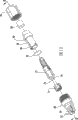
图12为图8中光纤插头的分解透视图,其中包括插头体、一对单纤套管、对准套筒、保护性牵引帽、压接带以及联结螺母;12 is an exploded perspective view of the fiber optic plug of FIG. 8, including a plug body, a pair of single-fiber ferrules, an alignment sleeve, a protective pulling cap, a crimping band, and a coupling nut;
图13为以组装构造示出图12所示的光纤插头的截面图;以及Figure 13 is a cross-sectional view showing the fiber optic plug shown in Figure 12 in an assembled configuration; and
图14为图8的插座和插头组件的端面图,其分解示出了该插座和插头组件的对准和键合机构。Fig. 14 is an end view of the receptacle and plug assembly of Fig. 8, exploded showing the alignment and keying mechanism of the receptacle and plug assembly.
具体实施方式Detailed ways
现在参照示出了本发明的示例性实施方式的附图将更全面地描述本发明。然而,本发明可以包括在许多不同形式中并且不应当被理解为限于此处所述的实施方式。提供这些示例性实施方式以使本公开更全面和完整,并将本发明的范围全面传达给本领域技术人员。在不同附图中,相同的附图标记表示相同的元件。The present invention will now be described more fully with reference to the accompanying drawings, in which exemplary embodiments of the invention are shown. However, this invention may be embodied in many different forms and should not be construed as limited to the embodiments set forth herein. These exemplary embodiments are provided so that this disclosure will be thorough and complete, and will fully convey the scope of the invention to those skilled in the art. In different drawings, the same reference numerals refer to the same elements.
在下述的各种实施方式中,本发明包括具有用于互连通信网络中的光纤的一个或多个光学连接器的光纤插座和插头组件。各组件的插座部分设计用于可安装在机柜的壁中或限定出一个或多个光纤可通过其中的外壁的类似结构。光纤插座的刚性肩部位于机柜的壁中并与其紧靠,因此与为了固定插座而在壁的内侧上使用螺纹螺母的传统组件相比,对外部拉伸力具有更优越的保持力。在此处示出和描述的示例性实施方式中,光纤插头部分安装在包括一个或多个光纤的光纤电缆的端部,这一个或多个光纤要与容纳在该组件的插座部分中相应的多个光纤光学连接。如此处使用的,该插头的光纤电缆称为“分支缆线”并旨在包括所有类型的光缆,诸如但不限于配线缆线、支线缆线、扩展的配线缆线、系缆、扁平介电分支缆线、8字形分支缆线或铠装分支缆线。并且,可以对此处描述的光纤插座和插头组件的具体部件进行必要修改以适应不同类型的光纤电缆。In various embodiments described below, the present invention includes fiber optic receptacle and plug assemblies having one or more optical connectors for interconnecting optical fibers in a communication network. The receptacle portion of each assembly is designed to be mountable in a wall of a cabinet or similar structure that defines an outer wall through which one or more optical fibers may pass. The rigid shoulder of the fiber optic receptacle sits in and abuts against the wall of the cabinet and therefore has superior retention against external tensile forces compared to traditional assemblies that use threaded nuts on the inside of the wall to secure the receptacle. In the exemplary embodiment shown and described herein, the fiber optic plug portion is mounted on the end of a fiber optic cable that includes one or more optical fibers that correspond to the optical fibers received in the receptacle portion of the assembly. Multiple fiber optic connections. As used herein, the plug's fiber optic cable is referred to as a "drop cable" and is intended to include all types of fiber optic cables, such as, but not limited to, distribution cables, drop cables, extended distribution cables, tether cables, Flat dielectric drop cables, figure-of-eight drop cables, or armored drop cables. Also, the specific components of the fiber optic receptacle and plug assemblies described herein can be modified mutatis mutandis to accommodate different types of fiber optic cables.
在所示的示例性的实施方式中,分支缆线包括缆线外壳、加强部件以及设置在缆线外壳中的光学传输部件。在一实施方式中,加强部件包括两玻璃增强塑料(GRP)加强部件并且光学传输部件包括设置在中央缓冲管内的光波导管。分支缆线还可以包括提供额外抗拉强度的加强构件。如此处使用的,术语“加强部件”是指具有抗弯强度(anti-buckling strength)的加强元件,而术语“加强构件”是指缺少抗弯强度的加强元件。此外,术语“承拉元件”一般是指加强部件或加强构件。由于因为加强构件未将所有抗拉强度提供给缆线从而允许加强部件具有较小直径,所以加强构件允许光缆具有较小截面区。换句话说,加强部件和加强构件都承载拉伸负荷。此外,通过使用加强构件,缆线保持相对柔软并易于操作。应当理解,其他缆线类型可以与本发明结合一起使用。另外,根据本发明原理,各种光学连接器可以与不同的光纤光缆一起使用,从而产生大量光纤电缆和连接器的组合。分支缆线优选地设计为在宽范围的温度下提供稳定性能并且与任意通信级的光纤兼容。如此处使用的,术语“光纤”旨在包括所有类型的单模和多模光波导,包括一个或多个裸露光纤、涂敷光纤、松套光纤、紧缓冲光纤、带光纤或为了传输光信号还未知或此后将开发的任意其他介质(expedient)。In the exemplary embodiment shown, the drop cable includes a cable housing, a strength member, and an optical transmission component disposed within the cable housing. In one embodiment, the strength member includes two glass reinforced plastic (GRP) strength members and the optical transmission member includes an optical waveguide disposed within a central buffer tube. The drop cables may also include strength members that provide additional tensile strength. As used herein, the term "strengthening component" refers to a strengthening element having anti-buckling strength, while the term "strengthening member" refers to a strengthening element lacking anti-buckling strength. Additionally, the term "tensile element" generally refers to a reinforcement component or reinforcement member. The strength member allows the fiber optic cable to have a smaller cross-sectional area because the strength member does not provide all the tensile strength to the cable, allowing the strength member to have a smaller diameter. In other words, both the reinforcement part and the reinforcement member carry the tensile load. Furthermore, through the use of strengthening members, the cables remain relatively flexible and easy to handle. It should be understood that other cable types may be used in conjunction with the present invention. Additionally, in accordance with the principles of the present invention, various optical connectors can be used with different fiber optic cables, resulting in a large number of fiber optic cable and connector combinations. The breakout cables are preferably designed to provide stable performance over a wide range of temperatures and to be compatible with any communication grade of fiber. As used herein, the term "optical fiber" is intended to include all types of single-mode and multimode optical waveguides, including one or more bare fibers, coated fibers, loose-buffered fibers, tightly buffered fibers, ribbon fibers or for the transmission of optical signals Any other expedient not yet known or hereafter to be developed.
本发明的光纤连接器和插头组件提供了防止潮气和污染物到达相对套管的端面的密封环境。在所有实施方式中,O形环或平的弹性垫圈提供了静密封。设置在插座和插头上与缓压构件(relief features)结合的密封的位置可在将插头从插座脱离时使真空增大(vacuum build-up)最小化以及在将插头配合插座时使压力增大(pressure build-up)最小化。一般而言,插座和插头组件的绝大多数部件由适合的聚合物形成。优选地,聚合物为GE塑料公司出产的诸如ULTEM 2210的UV稳定聚合物。然而,也可使用其它适合的高强度材料。例如,不锈钢或任何其它合适的金属可用于各种部件以提供甚至更坚固的插座和插头组件。The fiber optic connector and plug assemblies of the present invention provide a sealed environment that prevents moisture and contaminants from reaching the end faces of opposing ferrules. In all embodiments, O-rings or flat elastomeric gaskets provide the static seal. Positioning of the seal on the receptacle and plug in combination with relief features minimizes vacuum build-up when the plug is disengaged from the receptacle and pressure build-up when the plug is mated to the receptacle (pressure build-up) minimized. In general, the vast majority of components of the receptacle and plug assemblies are formed from suitable polymers. Preferably, the polymer is a UV stabilized polymer such as ULTEM 2210 from GE Plastics. However, other suitable high strength materials may also be used. For example, stainless steel or any other suitable metal could be used for the various components to provide an even stronger receptacle and plug assembly.
现在参照图1到图7,示出了根据本发明一个实施方式的光纤插座和插头组件。该组件包括光纤插座20和相应的光纤插头22。虽然未示出,插座20通常安装在此处称为“连接器端口”的开口中,该开口位于诸如光纤通信网络中的连接终端的机柜的外壁中。插座20可操作地用于将由连接终端的外部通过连接器端口的光纤与由连接终端的内部通过连接器端口的光纤相互连接。然而应该理解的是,光纤插座20可安装在包括可重复进入的连接终端的内壁的其它机柜以及结构。各连接器端口可操作地用于容纳连接终端内侧上的插座20和至少一个连接器化的(connectorized)光纤,以及连接终端外侧上的插头22和分支缆线24的至少一个连接器化的光纤。插头22安装在分支缆线24的端部并且适于配合相应的插座20。插头22和插座20可操作地用于将相对的光纤对准并保持物理接触。通过在插座20中提供多纤套管或者通过在插座20中提供多个单纤套管,单个连接器端口可与分支缆线24的多个光纤互连。单个连接器端口也可适于容纳多个插座20。Referring now to FIGS. 1-7 , there is shown a fiber optic receptacle and plug assembly in accordance with one embodiment of the present invention. The assembly includes a
具体参照图1,分解示出了插座20和相应的插头22并且去除了它们各自的防尘帽34和牵引帽28。该组件中插头22的螺纹联结螺母26,其可操作用于在啮合基础上将插头22固定至插座20,并且在安装过程中可用于固定该保护性的牵引帽28。该牵引帽28限定有在其后端的螺纹部分29和其前端的牵引环30。牵引帽28提供了在船运、配置以及直到与插座20接合的过程中插头22的光学连接器32的保护。使用绳索33,牵引帽28可与分支缆线24相连,从而如果该插头22在以后与插座20脱离时,也可重新使用该牵引帽28。在优选实施方式中,牵引环30应可承受高至600磅的缆线拉伸力。牵引环30和牵引帽28通常具有圆形的前端部以使得通过导管、输送管或滑轮或滑车之上的配置更容易。如同组件的插头22一样,插座20也可以由在将插头22插入插座20中之前需去除的带螺纹的防尘帽34覆盖并密封。防尘帽34也可使用绳索33与插座20相连。在与螺纹相对的插座20端部处,保护罩36对插座20提供保护,并在某些实施方式中还可以提供密封。保护密封罩36允许组件安装在可透气的机柜中,并可在插座20以另外的方式被可靠地密封而不受恶劣环境影响的情况下不再使用。Referring specifically to FIG. 1 , the
具体参照图2,光纤插头22安装在光纤分支缆线24的端部并适于配合相应的光纤插座20。为了将插头22和插座20固定在一起,联结螺母26与插座20的螺纹端部相啮合。以下将描述在贯穿连接终端的外壁的连接器端口中固定插座和插头的方式。Referring specifically to FIG. 2 , the
现在参照图3,光纤插座20包括可操作用于安装到连接终端的壁上的插座外壳38。如将在下文和图7中详细描述的那样,外壳38保持套管组件并对准该套管组件和光纤插头22,从而使得它们可仅在一个优选方向上接合。该特点利于包括要求角度偏移最小的角度物理接触(Angled Physical Contact)(APC)型套管以及经常不在中央周围的多纤套管的安装。插座外壳38限定有贯穿相对端的内腔40,所述相对端是第一端42和第二端44。通常,穿过第一端42的开口相对较大,以便容纳相应的光纤插头22。相反,穿过第二端44的开口通常较小,在一个优选实施方式中,其尺寸仅稍大于插座套管46,从而套管46可插入该开口。第一端42的相对大的开口允许使用棉签或特别的清洗工具清洗。由于相对于光纤插头而言,插座可能暴露于风雨中而同时在其可能聚集污染物的延长的时间段内并未被使用,所以该机构是有利的。该实施方式考虑到方便清洁以及改进的进出而不需要拆卸。Referring now to FIG. 3 , the
虽然光纤插座20可包括诸如SC、LC、MTRJ、MTP、SC-DC等的各种光纤连接器,但是本特定实施方式的插座20被表示为包括作为示例而不作为限制的单个SC连接器。虽然未包括在该特定的实施方式中,但是光纤插座20可包括设置在由插座外壳38限定的内腔40中的对准套筒。在图1到14所示的实施方式中,对准套筒为插头22的部件并在插头22的插入基础上插入到插座20的内腔40中。这种情况下,光纤插头22的插头套管插入到对准套筒的一端,同时安装在连接终端中的光纤端部的插座套管46穿过由插座20的第二端44限定的开口插入到对准套筒的另一端。While the
如图所示,插座外壳38为圆柱状并限定有在第一端42和第二端44之间中间位置的肩部部分48。在穿过连接终端外壁的安装基础上,将插座外壳38的第一端42从连接终端的内部插入该壁,直到面对第一端42的肩部部分48的径向表面紧靠该壁的内表面为止。通过使用肩部部分48将插座20固定在穿过连接终端外壁的开口中,相比于螺纹螺母,相对低规格的插座20可提供应变减缓以抵御高达约600磅的缆线拉伸力。优选地,使用O形环、弹性环、多点密封件50(如图示的)或类似的密封手段在插座外壳38的肩部部分48与该壁之间提供密封。插座外壳38在肩部部分48与螺纹部分之间限定有用于容纳多点密封件50的槽52。槽52可进一步容纳用于保持多点密封件50在适当位置并将插座20固定在由连接终端的壁中开口所限定的连接器端口中的月牙形环54。当插头22与插座20配合时,插头22的联结螺母26用于进一步将插座20固定在连接器端口中。As shown, the
光纤插座20还包括用于将插座套管46保持在插座外壳38的内腔40中的套管护圈56。套管护圈56和插座外壳38可以各种方式连接,但是在一个优选实施方式中,套管护圈56包括由从插座外壳38向外突出的构件60所接收的钩58。为了例如清洗、维修、替换等而到达插座套管46,套管护圈56可从插座外壳38上去除。套管护圈56的设计考虑到了不使用特殊工具而可轻易去除。一旦插座套管46做完必要的清洗、维修或更换以后,套管护圈56可重新与插座外壳38连接。The
该示例的实施方式的光纤插座20还包括设置在插座外壳38中的偏移构件。该偏移构件可操作地与插座套管46和套管护圈56接合以推动插座套管46朝向插座外壳38的第一端42。通常,偏移构件由一个或多个弹簧62组成。因此,插座套管46为弹簧承载式并允许在内腔40中轴向浮动,因此吸收插座套管46与相对的插头套管之间的压缩力。罩36保护位于连接终端的壁的内侧上的插座20的部件。保护罩36进一步限定有用于接纳来自连接终端内部的光纤和/或光纤电缆(未图示)的开口64。The
图4为沿图3的A-A线所取的已组装插座组件20的截面图,其中相同的部件使用相同的附图标记。O形环66可用于在防尘帽34与插座外壳38之间提供密封。如图4所示,多点密封件50保持在插座外壳38的槽52中并在插座外壳38与连接终端的壁之间提供密封点。该壁位于插座外壳38的肩部部分48与月牙形环54之间。在一个实施方式中,月牙形环54将插座20固定在合适位置。在另一实施方式,防尘帽34或光纤插头22的联结螺母26用于将插座20固定在合适位置。FIG. 4 is a cross-sectional view of the assembled
参照图5,光纤插头22进一步包括插头套管70、具有压接体的内壳72、对准套筒74、外壳68以及联结螺母26。为了在通常防止扭曲并且减缓插头22附近的分支缆线24的弯曲应变的同时密封分支缆线24的暴露部分,也可在外壳68的一部分以及分支缆线24的一部分之上固定由弹性(硅树脂型或其它类似物)材料制成的模制(molded-on)插头防护罩(未示出)。端接加强部件78并且在加强部件78周围固定压接带80。压接带80优选地由黄铜制成,但是可以使用其他合适的可变形材料。加强构件(未示出)被切成和已剥开的后护套76平齐,从而暴露出邻近分支缆线24端部的两GRP加强组件78和光学部件82。压接带80为缆线24提供应变减缓。通过首先将压接带80与缆线24压接而组装内壳72。随后外壳68滑动到内壳72之上。外壳68在内壳72之前拧到缆线24上。Referring to FIG. 5 , the
插头套管70至少部分设置在内壳72中并沿纵向延伸。所以,插头套管70可安装在内壳72中,从而插头套管70的前面略微延伸超出内壳72的前端。与相应的光纤插座20类似,光纤插头22可包括诸如SC、LC、MTRJ、MTP、SC-DC等的各种光纤连接器。由于插座20仅能接纳类似套管构造的插头,所以本示例的实施方式的插头22所示为包括单个SC连接器。对准套筒74限定有用于接纳插头套管70并且用于当插头22与插座20配合时接纳插座套管46的纵向通道。如上所述,对准套筒74可为插座20的部件,或者为插头22的部件,然而,在本示例实施方式中所示和所述的,其为插头22的部件。Plug
外壳68通常为具有前第一端84和后第二端86的圆柱状。外壳68通常保护内壳72并在优选实施方式中还对准并键合插头22与配合插座20的接合。并且,外壳68包括第一端84和第二端86之间的通道。内壳72的通道包括键合机构,从而使得一旦组装插头22,则禁止内壳72旋转。外壳68的第一端84包括用于将插头22与插座20对准、并且因此内壳72相对于插座20对准的键槽88(图5和图7)。将插头22和相应的插座20成形为仅允许在一个方向上配合。在优选实施方式中,该方向可使用对准标记在插座20和插头22上标出,从而不太熟练的现场技术人员也可轻易地将插头22与插座20配合。可使用任何合适的标记。在对准之后,现场技术人员将联结螺母26的内螺纹与插座20的外螺纹啮合以将插头22固定到插座20上。The
插头22的外壳68可进一步限定有为传统的弹性O形环92和联结螺母26提供机械限位的肩部90。当联结螺母26与插座20的螺纹部分啮合时,O形环92提供防风雨的密封。联结螺母26具有有一定大小的通道,以使其套在外壳68的第二端86上并容易地绕外壳68旋转。换句话说,联结螺母26不能在插座20的方向上移动超过肩部90,但是能够相对于外壳68旋转。图6为沿图5的B-B线所取的组装的插头22的截面图,其中相同的部件使用相同的附图标记。The
图7为图1的插座20和插头22的端面图,其进一步示出了该组件的对准和键合机构。如上所述,插头22与插座20配合以使得相应插头套管70和插座套管46进行光学连接。插座20和对准套筒74限定了对应于配合套管数量和类型的套管开口100。在图1到图7所示的实施方式中,一个套管开口100用于配合单纤SC套管,因此提供了“单式(simplex)”光学连接器。对准套筒74保持并定位于插头22的外壳68中,从而对准套筒74的键槽102与由插头外壳68限定的键槽88对准,在优选实施方式中,插头外壳68邻近第一端84沿着其长度方向限定了用于接纳由对准套筒74所限定的机构106的一对开口104。为了恰当地将对准套筒74对准在插头外壳68中,机构106由开口104接纳,因此正确地将对准套筒74的键槽102与外壳68的键槽88对准。FIG. 7 is an end view of the
为了进行光学连接,插头22插入插座20。插座20可仅接纳类似套筒构造的插头22。插座20限定有接纳在插头外壳68的键槽88和对准套筒74的键槽102中的键108。如图所示,键108为成型在插座20中的“T”形结构。可为各类型和/或多种套管产生具有特定键形的插座。在可替换的实施方式中,具有特定键形的插入物可插入到插座外壳38中以容纳特定的连接器,因此,可允许通用的插座外壳用于不同的连接器类型。在连接上,键108仅接受类似套管构造的插头22,同时也恰当地将插头22对准在插座20中。因为对准和键合机构延伸到插头22端部周围,所以具有与插座20不同套管构造的插头22不能插入到插座20中,从而消除了对套管的潜在损害。在配合APC套管时,对准方向特别重要。APC套管的端面以非正交的角度设置,并通常以相对于与由套管所限定的纵轴垂直的平面约6度到约11度之间的角度设置。通常,APC套管的端面以相对于与由套管所限定的纵轴垂直延伸的平面约8度的角度设置。为了正确地互连一对相对的APC套管的光纤,套管必须定位使得带有角度的端面彼此互补,也就是,一个套管的端面的最前部分与另一套管的端面的最后部分彼此相对。为了使得这种互补方式的套管的对准更容易,以相对于套管的端面的预定方向设置键108。For an optical connection, a
参照图8,分解示出了双纤式的光纤插座和插头组件,其中插座20和插头22去除了各自的防尘帽和牵引帽。在本实施方式中,为了清晰起见,未示出包括两个光波导的分支缆线。如图1到图7所示的实施方式一样,插座20安装在由穿过连接终端外壁的开口所限定的连接器端口中。插头22仅与类似光学连接器和套管构造的插座20对准并接合。所示的插头22允许连接终端的单个插座20容纳分支缆线的多个光纤以与连接终端中端接自配线缆线的多个光纤进行光学连接。同时,与插头22相连的分支缆线在连接器端口被减缓应变以抵抗高达600磅的分支缆线拉伸力。Referring to FIG. 8 , an exploded view shows a dual-fiber fiber optic receptacle and plug assembly, wherein the
插座20和相应的插头22被分解示出,并且去除了它们各自的防尘帽34和牵引帽28。该组件的插头22的螺纹联结螺母26可操作用于在船运和配置过程中固定该保护性的牵引帽28,并可操作用于在插头22和插座20配合时在啮合的基础上将插头22固定到插座20。保护罩36允许组件安装在可透气的机柜中,并在插座20以另外的方式被可靠地密封在连接终端内而不被环境影响的情况下可不再使用。如前实施方式所述的,插头外壳68通常为圆柱状并包括用于将插头22与插座20配合的对准和键合机构。具体地,外壳68限定有插头22上的对准和键合机构。如此处及前所述的,对准和键合机构形成为纵向键槽94的形式。键槽94具有特定的形状,从而使得插头22和插座20仅在一个方向上配合。在优选实施方式中,该方向可在外壳68和插座外壳38上标出,从而使得不太熟练的现场技术人员通过将外壳68上的对准标记与设置在插座外壳38上的互补的对准标记对准,也可轻易地将插头22与插座20配合。此后,现场的技术人员将联结螺母26的内螺纹与插座外壳38的外螺纹啮合以将插头22固定到插座20上。The
参照图9,由于所示的光学连接器包括诸如一对LC套管的多个套管,所以光纤插头22可安装在包括多个光纤的任何适合的光纤分支缆线上。为了固定插头22和插座20,联结螺母26与插座20的螺纹端部啮合。在没有特殊工具、设备或培训的现场也可以固定插头22。另外,通过联结螺母26的螺纹与插座20的螺纹啮合或不啮合,可轻易地连接或断开物理连接,从而配合或不配合插头22和插座20。因此,本发明的插座和插头组件允许以简单和经济的方式配置穿过在传统的网络连接终端的外壁中提供的连接器端口的多条光纤。Referring to FIG. 9, since the illustrated optical connector includes multiple ferrules, such as a pair of LC ferrules, the
参照图10,如在如上所述的实施方式中那样,光纤插座20包括插座外壳38,该插座外壳38可操作用于安装在壁上,并同时保持套管以及将该套管对准光纤插头22从而它们可以仅在优选的方向上接合。插座外壳38限定有贯穿相对端的内腔40,所述相对端是第一端42和第二端44。穿过第二端44的开口通常较小,在一个优选实施方式中,其尺寸仅稍大于插座套管46,从而插座套管46可插入该开口。虽然光纤插座20可包括诸如SC、LC、MTRJ、MTP、SC-DC等的各种光纤连接器,但是本特定实施方式的插座20被表示为包括作为示例而不作为限制的一对LC连接器。如前所述的实施方式中那样,对准套筒74为插头22的部件并在插头22穿过插座20的第一端42的插入基础上插入到插座20的内腔40中。10, as in the embodiments described above, the
本实施方式中所示的插座外壳38为圆柱状并限定有在第一端42和第二端44之间中间位置的肩部48。在穿过连接终端外壁的连接器端口中的插座20的安装基础上,将插座外壳38的第一端42从连接终端的内部插入该壁,直到面对第一端42的肩部48的表面与该壁的内表面接触为止。可以使用O形环(未示出)、多点密封件50或类似的密封手段在插座外壳38与该壁之间提供密封。插座20还包括可操作用于将插座套管46保持在插座外壳38的内腔40中的套管护圈56。套管护圈56限定了夹持由插座外壳38限定的构件60的夹或钩58。为了例如清洗、维修、替换等而到达插座套管46,套管护圈56可从插座外壳38上去除。The
本示例的实施方式的光纤插座20还包括设置在插座外壳38中的偏移构件。该偏移构件可操作地与插座套管46和套管护圈56结合以推动插座套管46朝向插座外壳38的第一端42。通常,偏移构件包括一个或多个弹簧62。因此,插座套管46为弹簧承载式并由此允许在内腔40中轴向浮动,因此可吸收插座套管46与相对的插头套管之间的压缩力。然而,应该理解除了或替代一个或多个弹簧62以外,光纤插座20可包括其它类型的偏移构件。套管护圈56也可包括一个或多个沿纵向方向延伸的柱(未示出),从而弹簧可安装在各柱上。在这种情况下,各弹簧62即使在压缩状态下也会长于其各自的柱。这样,该柱用于定位与插座套管46接触的弹簧62。图11为沿图10的C-C线所取的已组装插座20的截面图,其中相同的部件使用相同的附图标记。弹性O形环密封66可设置在防尘帽34与插座外壳38之间。光纤插座20适于接纳相应的光纤插头22,从而光纤插头22的插头套管70与插座外壳38的第一端42对准并插入其中。The
参照图12,与图10和图11中所示的插座20相对应的光纤插头22通常包括插头内壳72、插头套管70、对准套筒74、外壳68以及联结螺母26。还可在外壳68的一部分以及分支缆线(未示出)的一部分之上固定由弹性(硅树脂型或其它类似物)材料制成的模制插头防护罩(未示出)以密封插头22附近的缆线并减缓其弯曲应变。压接带80固定在缆线的加强部件(未示出)周围并为缆线提供应变减缓。插头套管70部分地设置在内壳72中并沿纵向延伸。为了匹配相应的插座20,光纤插头22可包括诸如SC、LC、MTRJ、MTP、SC-DC等的各种光纤连接器。本示例的实施方式的插头22所示为包括一对小于SC连接器的LC连接器,因此允许该组件的直径与前述示例的实施方式保持相同。为了插头套管70与插座套管46配合,插头套管70容纳在由对准套筒74限定的纵向通道中。插座套管46插入到对准套筒74的开放的前端。因此,当插头22插入插座20中时,对准套筒74用于将位于其中的插头套管70与接纳在其另一端内的插座套管46进行对准。这样,其上安装有各自套管的光纤也相应地对准并光学相连。Referring to FIG. 12 , a
外壳68通常保护内壳72并在优选实施方式中还对准并键合插头22与插座20的配合。并且,内壳72包括用于键合的通道,从而使得在组装插头22时禁止内壳72旋转。外壳68包括由外壳68所限定的键槽88,其用于将插头22与插座20对准。将插头22和相应的插座20成形为仅允许在一个方向上配合。在对准之后,现场的技术人员将联结螺母26的内螺纹与插座20的外螺纹啮合以将插头22固定到插座20上。The
外壳68可进一步限定有为O形环92和联结螺母26提供机械限位的肩部90。O形环92在插头22与插座20之间提供防风雨的密封。联结螺母26具有有一定大小的通道,以使其套在外壳68的端部上并容易地绕外壳68旋转。图13为沿图12的D-D线所取的已组装插头22的截面图,其中相同的部件使用相同的附图标记。
图14为图8的插座20和插头22的端面图,其进一步示出了该组件的对准和键合机构。插座20和对准套筒74限定了分别对应于插座套管46和插头套管70的数量和类型的套管开口100。在图8到图13所示的实施方式中,一对套管开口100用于分别配合一对相对的LC插座套管46和LC插头套管70,因此提供了“复式(duplex)”光学连接器。对准套筒74被保持并定位于插头22的外壳68中,从而对准套筒74的键槽102与由插头外壳68限定的键槽88对准。在优选实施方式中,为了接纳由对准套筒74所限定的机构106,插头外壳68沿着其长度方向限定了一对开口104。为了恰当地将对准套筒74对准在插头外壳68中,机构106由开口104接纳,因此可正确地将对准套筒74的键槽102与外壳68的键槽88对准。对准套筒74的键槽102优选地特定于各连接器类型,而外壳68的键槽88可通用于所有的连接器类型,因此允许对所有的连接器类型使用公用的插头外壳68。FIG. 14 is an end view of the
为了进行光学连接,插头22插入插座20。插座20配置为仅接纳类似套管构造的插头22。插座20限定有接纳在插头外壳68的键槽88和对准套筒74的键槽102中的键108。如图所示,键108为成型在插座20中的“I”形结构。可为各类型和/或多种套管产生具有特定键形的插座。在可替换的实施方式中,具有特定键形的插入物可插入到插座外壳38中以纳容特定的连接器,因此,可允许通用的插座外壳用于不同的连接器类型。在连接上,键108仅接受类似套管构造的插头22,同时也恰当地将插头22对准在插座20中。因为对准和键合机构延伸到插头22的端部周围,所以具有与插座20不同套管构造的插头22不能插入到插座20中,从而消除了对插座套管46和插头套管70的潜在损害。For an optical connection, a
在替换的实施方式中,联结螺母26和插座外壳38的螺纹可由卡销或推拉式机构替代来将插头22固定到插座20中。可替换的,可增加弹簧夹或相似装置以将插头22与插座20接合以将它们固定在一起。根据该组件暴露在恶劣环境中的程度,可去除或放松密封。插头防护罩可预先制造并组装到插头内壳72和分支缆线24上,或可以使用由North Carolina,Hickory的Corning Cable Systems LLC提供的技术包覆成型(overmolded)。并且,当外观不太重要且弯曲特性不太严格时,可使用热可收缩管材以实现与防护罩相同的目的。如前所述,在保持相同的组装技术并考虑到便于去除和清洗的同时,可将对准套筒74集成在插座20中。In alternative embodiments, the threads of the
由这里所示出的以及描述的基本设计可以推导得出多种类型的套管(包括多纤)的设计。根据可用空间和需要而得出的多纤套管设计是可能的,诸如MTP、MTRJ、DC、1.25mm多纤、2.5mm多纤等。如果需要,可为插座20增加额外的应变减缓。根据分支缆线的类型和要求,压接方案可以不同。如果分支缆线未包括如在第一实施方式中所示的双GRP介电加强构件,则将加强构件结合到插头体的方法可包括胶结或诸如夹持的其它紧固手段。From the basic design shown and described here, designs of various types of bushings, including multi-fiber, can be derived. Multi-fiber sleeve designs are possible according to available space and needs, such as MTP, MTRJ, DC, 1.25mm multi-fiber, 2.5mm multi-fiber, etc. Additional strain relief can be added to
上述实施方式在传统的光纤插座和插头组件基础上具有优点。例如,在此所述的示例性实施方式的小尺寸考虑了对于FTTx配线缆线的约38mm直径捆包,并允许插座安装在要求插座进入终端或机柜非常小的插入深度的连接终端或其它机柜。这些组件的对准和键合机构使它们具有充分APC性能,并且唯一的配合可防止在制造和安装过程中的组装误差。通过将对准套筒74设置在与插座20相对的插头22中,可减小插座的体积并且可易于到达并清洗在延长的时间段中暴露于恶劣环境中的插座20的部件。包覆成型的防护罩消除了热可收缩管材的需求并且在预先成形的防护罩可能与插头22脱离的恶劣条件下也改善了组件的密封完整性。The above-described embodiments provide advantages over conventional fiber optic receptacle and plug assemblies. For example, the small size of the exemplary embodiments described herein allows for approximately 38 mm diameter bundles of FTTx distribution cable wires and allows the receptacle to be installed in connection terminals or other connections that require very small insertion depths of the receptacle into terminals or cabinets. cabinet. The alignment and bonding mechanisms of these components make them fully APC capable, and the unique fit prevents assembly errors during manufacturing and installation. By positioning the
前述为仅以示例方式给出的本发明的各种实施方式的描述。虽然光纤插座和插头组件参照优选实施方式及其示例得到描述,但是其它实施方式和示例也可执行相似的功能或取得相似的结果。所有这些等效的实施方式和示例均在本发明的构思和范围内并旨在由所附的权利要求书所覆盖。The foregoing description of various embodiments of the invention has been presented by way of example only. While fiber optic receptacle and plug assemblies have been described with reference to preferred embodiments and examples thereof, other embodiments and examples can perform similar functions or achieve similar results. All such equivalent embodiments and examples are within the spirit and scope of the present invention and are intended to be covered by the appended claims.
Claims (19)
Applications Claiming Priority (3)
| Application Number | Priority Date | Filing Date | Title |
|---|---|---|---|
| US10/924,525 US20060045428A1 (en) | 2004-08-24 | 2004-08-24 | Fiber optic receptacle and plug assemblies |
| US10/924,525 | 2004-08-24 | ||
| PCT/US2005/005967 WO2006022840A1 (en) | 2004-08-24 | 2005-02-25 | Fiber optic receptacle and plug assemblies with alignment and keying features |
Publications (2)
| Publication Number | Publication Date |
|---|---|
| CN101006376A CN101006376A (en) | 2007-07-25 |
| CN101006376B true CN101006376B (en) | 2011-01-26 |
Family
ID=34961466
Family Applications (1)
| Application Number | Title | Priority Date | Filing Date |
|---|---|---|---|
| CN2005800277028A Expired - Lifetime CN101006376B (en) | 2004-08-24 | 2005-02-25 | Fiber Optic Receptacle and Plug Assemblies with Alignment and Keying Mechanisms |
Country Status (11)
| Country | Link |
|---|---|
| US (2) | US20060045428A1 (en) |
| EP (1) | EP1782114B1 (en) |
| JP (1) | JP4871862B2 (en) |
| CN (1) | CN101006376B (en) |
| AT (1) | ATE476679T1 (en) |
| AU (1) | AU2005278173B2 (en) |
| CA (1) | CA2576507C (en) |
| DE (1) | DE602005022732D1 (en) |
| ES (1) | ES2350047T3 (en) |
| MX (1) | MX2007001583A (en) |
| WO (1) | WO2006022840A1 (en) |
Families Citing this family (127)
| Publication number | Priority date | Publication date | Assignee | Title |
|---|---|---|---|---|
| US7467896B2 (en) * | 2000-05-26 | 2008-12-23 | Corning Cable Systems Llc | Fiber optic drop cables and preconnectorized assemblies |
| US9239441B2 (en) | 2000-05-26 | 2016-01-19 | Corning Cable Systems Llc | Fiber optic drop cables and preconnectorized assemblies having toning portions |
| US7113679B2 (en) * | 2000-05-26 | 2006-09-26 | Corning Cable Systems, Llc | Fiber optic drop cables and preconnectorized assemblies having toning portions |
| US7471862B2 (en) | 2002-12-19 | 2008-12-30 | Corning Cable Systems, Llc | Dry fiber optic cables and assemblies |
| US6962445B2 (en) | 2003-09-08 | 2005-11-08 | Adc Telecommunications, Inc. | Ruggedized fiber optic connection |
| US7699533B2 (en) * | 2003-09-22 | 2010-04-20 | Belden Cdt (Canada) Inc. | Back-to-back receptacle |
| US7785019B2 (en) * | 2005-03-10 | 2010-08-31 | Corning Cable Systems Llc | Multi-fiber fiber optic receptacle and plug assembly |
| US7264402B2 (en) * | 2005-03-10 | 2007-09-04 | Corning Cable Systems Llc | Multi-fiber optic receptacle and plug assembly |
| EP1875287A1 (en) * | 2005-04-19 | 2008-01-09 | ADC Telecommunications, Inc. | Loop back plug and method |
| US7764190B2 (en) * | 2005-09-30 | 2010-07-27 | Universal Electronics Inc. | System using a fiber optic cable to distribute commands for controlling operations of an appliance |
| US7572065B2 (en) | 2007-01-24 | 2009-08-11 | Adc Telecommunications, Inc. | Hardened fiber optic connector |
| US7614797B2 (en) | 2007-01-24 | 2009-11-10 | Adc Telecommunications, Inc. | Fiber optic connector mechanical interface converter |
| US7591595B2 (en) | 2007-01-24 | 2009-09-22 | Adc Telelcommunications, Inc. | Hardened fiber optic adapter |
| US7556437B2 (en) * | 2007-03-13 | 2009-07-07 | Adc Telecommunications, Inc. | Fiber optic connector with protective cap |
| US7585116B2 (en) * | 2007-04-12 | 2009-09-08 | Fiber Systems International | Fiber optic connector having hermaphroditic coupling mechanism |
| WO2008137897A1 (en) | 2007-05-06 | 2008-11-13 | Adc Telecommunications, Inc. | Mechanical interface converter for making non-ruggedized fiber optic connectors compatible with a ruggedized fiber optic adapter |
| WO2008137893A1 (en) | 2007-05-06 | 2008-11-13 | Adc Telecommunications, Inc. | Interface converter for sc fiber optic connectors |
| US7686519B2 (en) | 2007-06-18 | 2010-03-30 | Adc Telecommunications, Inc. | Hardened fiber optic housing and cable assembly |
| US7744286B2 (en) | 2007-12-11 | 2010-06-29 | Adc Telecommunications, Inc. | Hardened fiber optic connection system with multiple configurations |
| US7708469B2 (en) * | 2008-04-11 | 2010-05-04 | Corning Cable Systems Llc | Fiber optic connector assembly and method for venting gas inside a fiber optic connector sub-assembly |
| EP2283390B1 (en) * | 2008-04-21 | 2016-11-09 | ADC Telecommunications, INC. | Hardened fiber optic connector with connector body joined to cylindrical cable by unitary housing |
| US9195011B2 (en) * | 2008-12-11 | 2015-11-24 | Afl Telecommunications Llc | “Secured” fiber optic connecting system and method using offset fiber position in a single-fiber connector |
| US7941021B2 (en) * | 2008-12-22 | 2011-05-10 | Corning Cable Systems Llc | Distribution cable assembly having mid-span access location |
| US8646989B2 (en) | 2009-05-19 | 2014-02-11 | Adc Telecommunications, Inc. | Mechanical interface between a fiber optic cable and a fiber optic connector |
| PL2759860T3 (en) | 2009-09-28 | 2018-07-31 | Te Connectivity Nederland B.V. | Sealing enclosure for a connector on a cable, such as a standardised fibre-optic connector |
| US20110073818A1 (en) * | 2009-09-29 | 2011-03-31 | Avago Technologies Fiber Ip (Singapore) Pte. Ltd. | Pulling torpedo having a mating feature thereon that mates with a mating feature formed on a cable boot |
| WO2011056782A1 (en) * | 2009-11-04 | 2011-05-12 | Hogue Surgical, Llc | Adjustable optical fiber connector |
| US8272790B2 (en) * | 2009-11-24 | 2012-09-25 | Amphenol Fiber Optics | Outdoor transceiver connector |
| EP2355283A1 (en) | 2010-01-29 | 2011-08-10 | Tyco Electronics Raychem BVBA | Cable sealing device, cable termination and attaching device |
| PT2355286T (en) | 2010-01-29 | 2019-05-08 | Tyco Electronics Raychem Bvba | WATERPROOFING AND CABLE RETENTION DEVICE |
| ES2755911T3 (en) * | 2010-02-04 | 2020-04-24 | Commscope Technologies Llc | Reinforced fiber optic and electrical connection system |
| US8221006B2 (en) | 2010-08-23 | 2012-07-17 | Corning Cable Systems Llc | Fiber optic cable assemblies with mechanically interlocking crimp bands and methods of making the assemblies |
| US8267596B2 (en) * | 2010-08-23 | 2012-09-18 | Corning Cable Systems Llc | Fiber optic cable assemblies with fiber access apertures and methods of assembly |
| US8622481B2 (en) | 2011-01-25 | 2014-01-07 | Joy Mm Delaware, Inc. | Fiber optic cable protection in a mining system |
| DE102011011523B4 (en) | 2011-02-17 | 2013-05-29 | Tyco Electronics Services Gmbh | Fiber optic connection arrangement and adapter sleeve |
| US8540435B2 (en) | 2011-07-22 | 2013-09-24 | Corning Cable Systems Llc | Ferrule retainers having access window(s) for accessing and/or referencing a fiber optic ferrule, and related fiber optic connector assemblies, connectors, and referencing methods |
| US8388235B1 (en) * | 2011-07-24 | 2013-03-05 | Northrop Grumman Systems Corporation | Modular, optical, wet-mate connector |
| EP2745155B1 (en) | 2011-08-16 | 2019-11-20 | Corning Optical Communications LLC | Preconnectorized cable assemblies for indoor/outdoor applications |
| CN103959120B (en) | 2011-09-27 | 2016-08-17 | 安费诺有限公司 | Optical connector assembly |
| WO2013117589A2 (en) | 2012-02-07 | 2013-08-15 | Tyco Electronics Raychem Bvba | Cable termination assembly and method for connectors |
| US8998503B2 (en) * | 2012-05-16 | 2015-04-07 | Corning Cable Systems Llc | Fiber optic connector and bonded cover |
| ES1110405Y (en) | 2012-06-26 | 2014-08-19 | Huawei Tech Co Ltd | Fiber optic connector comprising a fiber optic connector assembly and a fiber optic adapter |
| US9696500B2 (en) | 2012-08-31 | 2017-07-04 | Corning Optical Communications LLC | Female hardened optical connectors for use with hybrid receptacle |
| US8939654B2 (en) | 2012-09-27 | 2015-01-27 | Adc Telecommunications, Inc. | Ruggedized multi-fiber fiber optic connector with sealed dust cap |
| US9028154B2 (en) * | 2013-02-01 | 2015-05-12 | Avago Technologies General Ip (Singapore) Pte. Ltd. | Adapter for cleaning an optical junction and reducing optical back reflection |
| US9411110B2 (en) * | 2013-02-06 | 2016-08-09 | Corning Optical Communications LLC | Fiber optic connector cover and fiber optic assembly including same |
| US9513444B2 (en) | 2013-02-26 | 2016-12-06 | Corning Optical Communications LLC | Female hardened optical connectors for use with male plug connectors |
| NZ711931A (en) * | 2013-03-26 | 2018-03-23 | Prysmian Spa | Automated tightener for a wet mateable connection assembly |
| WO2014179376A2 (en) | 2013-05-02 | 2014-11-06 | Corning Optical Communications LLC | Connector assemblies and methods for providing sealing and strain-relief |
| WO2014186436A1 (en) * | 2013-05-16 | 2014-11-20 | Corning Optical Communications LLC | Optical plug having a removable and replaceable nosepiece and a complimentary receptacle |
| US10444443B2 (en) | 2013-06-27 | 2019-10-15 | CommScope Connectivity Belgium BVBA | Fiber optic cable anchoring device for use with fiber optic connectors and methods of using the same |
| MX342434B (en) * | 2013-11-12 | 2016-09-29 | Huawei Tech Co Ltd | Optical fibre connection head, optical fibre adaptor and optical fibre connector. |
| MX380740B (en) | 2014-05-12 | 2025-03-12 | Corning Optical Communications LLC | FIBER OPTIC CABLE ASSEMBLIES FOR TERMINATING A FIBER OPTIC CABLE AND MANUFACTURING METHODS THEREOF. |
| CN105445862B (en) | 2014-07-09 | 2018-01-19 | 泰科电子(上海)有限公司 | The joints of optical fibre and its on-site assembly method |
| EP3180644B1 (en) | 2014-08-14 | 2020-02-26 | CommScope Connectivity Belgium BVBA | Fiber optic adapter assembly |
| CN204359965U (en) | 2014-11-20 | 2015-05-27 | 泰科电子(上海)有限公司 | Connector system |
| WO2016085839A1 (en) | 2014-11-26 | 2016-06-02 | Corning Optical Communications LLC | Fiber optic connectors and sub-assemblies with strength member retention |
| US10180541B2 (en) | 2014-12-19 | 2019-01-15 | CommScope Connectivity Belgium BVBA | Hardened fiber optic connector with pre-compressed spring |
| EP3245544A4 (en) | 2015-01-12 | 2018-07-11 | AFL Telecommunications LLC | Fiber optic terminal enclosure |
| CN107430249B (en) | 2015-03-06 | 2019-11-08 | 株式会社藤仓 | Plug-side optical connectors and optical connector systems |
| BR112017024540A2 (en) | 2015-05-15 | 2018-07-24 | Corning Optical Communications LLC | fiber optic cable assembly for fiber optic cable termination and manufacturing methods |
| CN106291826B (en) * | 2015-05-20 | 2019-05-28 | 华为技术有限公司 | Plug Protective Caps, Fiber Optic Connector Assemblies, Fiber Optic Plugs and Network Equipment |
| USD800659S1 (en) | 2015-06-05 | 2017-10-24 | Corning Optical Communications LLC | Fiber optic connector |
| USD800660S1 (en) | 2015-06-05 | 2017-10-24 | Corning Optical Communications LLC | Fiber optic connector |
| CN108027485B (en) * | 2015-09-14 | 2020-10-13 | 康普连通比利时私人有限公司 | Terminal housings in modular form and modules that interface with the terminal housings |
| US10520692B2 (en) | 2015-11-11 | 2019-12-31 | Afl Telecommunications Llc | Optical connection terminals for fiber optic communications networks |
| US10473868B2 (en) | 2015-11-30 | 2019-11-12 | Corning Optical Communications, Llc | Optical connector plug having a removable and replaceable mating interface |
| US9971100B2 (en) * | 2016-03-01 | 2018-05-15 | Leviton Manufacturing Co., Inc. | Methods and devices for preventing contamination of fiber optic connectors |
| US9864156B1 (en) * | 2016-07-01 | 2018-01-09 | 3M Innovative Properties Company | Multi-purpose sealing device |
| US11073670B2 (en) | 2016-08-12 | 2021-07-27 | Corning Optical Communications LLC | Device and method for sealing multiport splitters |
| EP3507632A4 (en) * | 2016-09-01 | 2020-04-01 | Commscope Technologies LLC | End face cleaning gel for hardened multi-fiber optical connectors; and methods |
| JP6421149B2 (en) * | 2016-09-02 | 2018-11-07 | 株式会社フジクラ | Optical connector and optical connector connection method |
| JP2018036590A (en) * | 2016-09-02 | 2018-03-08 | 株式会社フジクラ | Optical connector |
| CN106383393A (en) * | 2016-11-21 | 2017-02-08 | 金信诺(常州)轨道信号系统科技有限公司 | Bendable sealing protective device for jumper wire end portion |
| ES2725000B2 (en) * | 2017-02-14 | 2020-06-19 | Furukawa Electric Latam S A | CONNECTOR FOR FIBER OPTIC CABLE AND CLAMP FOR FIBER OPTIC CABLE |
| CN206479676U (en) * | 2017-02-16 | 2017-09-08 | 光联通讯有限公司 | Optical fiber socket, optical fiber connection device and optical fiber socket module |
| US10923897B2 (en) * | 2017-03-20 | 2021-02-16 | Pentair Flow Services Ag | Cable sealing gland |
| US9977211B1 (en) | 2017-04-21 | 2018-05-22 | Afl Telecommunications Llc | Optical connection terminals for fiber optic communications networks |
| EP3615970B1 (en) * | 2017-04-25 | 2024-06-05 | CommScope Connectivity Belgium BVBA | Connection module for cable seal gel block |
| US11115735B2 (en) * | 2017-05-30 | 2021-09-07 | Commscope Technologies Llc | Reconfigurable optical networks |
| AU2018284214A1 (en) | 2017-06-12 | 2019-12-05 | Commscope Technologies Llc | Distributed tap architecture incorporating hardened connectivity |
| WO2019005196A1 (en) | 2017-06-28 | 2019-01-03 | Corning Research & Development Corporation | Compact fiber optic connectors having multiple connector footprints, along with cable assemblies and methods of making the same |
| US12271040B2 (en) | 2017-06-28 | 2025-04-08 | Corning Research & Development Corporation | Fiber optic extender ports, assemblies and methods of making the same |
| US11187859B2 (en) | 2017-06-28 | 2021-11-30 | Corning Research & Development Corporation | Fiber optic connectors and methods of making the same |
| US11300746B2 (en) | 2017-06-28 | 2022-04-12 | Corning Research & Development Corporation | Fiber optic port module inserts, assemblies and methods of making the same |
| US10359577B2 (en) | 2017-06-28 | 2019-07-23 | Corning Research & Development Corporation | Multiports and optical connectors with rotationally discrete locking and keying features |
| US11668890B2 (en) | 2017-06-28 | 2023-06-06 | Corning Research & Development Corporation | Multiports and other devices having optical connection ports with securing features and methods of making the same |
| WO2019130580A1 (en) * | 2017-12-28 | 2019-07-04 | 株式会社フジクラ | Optical connector and method for connecting optical connector |
| EP3776752A4 (en) | 2018-04-02 | 2021-12-22 | Senko Advanced Components Inc. | HYBRID INPUT PROTECTED CONNECTOR AND ADAPTER ASSEMBLY |
| US10948664B2 (en) | 2018-05-08 | 2021-03-16 | Senko Advanced Components, Inc. | Ingress protected optical fiber connector having a reduced diameter with a removable retaining nut |
| US11209599B2 (en) * | 2018-07-05 | 2021-12-28 | Senko Advanced Components, Inc. | Ingress protected, outdoor rated adapter and method of assembly to an outdoor connector |
| US11092756B2 (en) | 2018-10-10 | 2021-08-17 | Senko Advanced Components, Inc. | Ingress protected connector with an unitary orientation feature |
| US10976502B2 (en) | 2018-10-11 | 2021-04-13 | Seniko Advanced Components, Inc. | Outdoor rated assembly configured to blind mate opposing fiber optic connectors therein with a safety spring assembly |
| US10641967B1 (en) | 2018-11-16 | 2020-05-05 | Corning Research & Development Corporation | Multiport assemblies including a modular adapter support array |
| EP3887883B1 (en) | 2018-11-29 | 2023-11-08 | Corning Research & Development Corporation | Multiport having connection ports with rotating actuators |
| US10768382B2 (en) | 2018-11-29 | 2020-09-08 | Corning Research & Development Corporation | Multiport assemblies including access apertures and a release tool |
| CA3125271C (en) | 2018-12-28 | 2024-02-27 | Corning Research & Development Corporation | Multiport assemblies including mounting features or dust plugs |
| US11307359B2 (en) | 2019-02-07 | 2022-04-19 | Senko Advanced Components, Inc. | Ingress protected, outdoor rated connector with integrated optical connector plug frame |
| US11531166B2 (en) | 2019-04-29 | 2022-12-20 | Corning Research & Development Corporation | Optical connector assemblies, optical receptacle assemblies and optical connection systems having multiple optical fibers |
| MX2021014427A (en) | 2019-05-31 | 2022-03-04 | Corning Res & Dev Corp | MULTIPORTS AND OTHER DEVICES THAT HAVE OPTICAL CONNECTION PORTS WITH SLIDING ACTUATORS AND METHODS FOR MAKING SAME. |
| CN112099153B (en) * | 2019-06-17 | 2025-04-01 | 泰科电子(上海)有限公司 | Connector module |
| US11906795B2 (en) | 2019-06-19 | 2024-02-20 | Senko Advanced Components, Inc. | Fiber optic connector assembly with crimp tube subassembly and method of use |
| JP6792673B1 (en) * | 2019-06-25 | 2020-11-25 | 日本航空電子工業株式会社 | Plug connector |
| US11294133B2 (en) | 2019-07-31 | 2022-04-05 | Corning Research & Development Corporation | Fiber optic networks using multiports and cable assemblies with cable-to-connector orientation |
| CN110308525B (en) * | 2019-08-07 | 2025-04-04 | 广东亿源通科技股份有限公司 | A pulling type optical fiber connector |
| US11422318B2 (en) | 2019-08-08 | 2022-08-23 | Senko Advanced Components, Inc. | Push pull mechanism for an outdoor rated connector assembly |
| US11487073B2 (en) | 2019-09-30 | 2022-11-01 | Corning Research & Development Corporation | Cable input devices having an integrated locking feature and assemblies using the cable input devices |
| EP3805827B1 (en) | 2019-10-07 | 2025-07-30 | Corning Research & Development Corporation | Fiber optic terminals and fiber optic networks having variable ratio couplers |
| PL4045957T3 (en) | 2019-10-18 | 2024-04-29 | Corning Research & Development Corporation | Terminals having optical connection ports with securing features providing stable retention forces |
| US11650388B2 (en) | 2019-11-14 | 2023-05-16 | Corning Research & Development Corporation | Fiber optic networks having a self-supporting optical terminal and methods of installing the optical terminal |
| JP7295000B2 (en) * | 2019-12-05 | 2023-06-20 | 住友電工オプティフロンティア株式会社 | Optical connector adapter caps and optical connector assemblies |
| US12210196B2 (en) * | 2019-12-13 | 2025-01-28 | Us Conec Ltd. | Cover for a fiber optic ferrule and ferrule push |
| US11536921B2 (en) | 2020-02-11 | 2022-12-27 | Corning Research & Development Corporation | Fiber optic terminals having one or more loopback assemblies |
| WO2021178230A1 (en) * | 2020-03-02 | 2021-09-10 | Corning Research & Development Corporation | Optical fiber cable tensile strength limiting system |
| EP4154045A1 (en) * | 2020-05-20 | 2023-03-29 | CommScope Technologies LLC | Active optical cable assemblies |
| EP4172671B1 (en) | 2020-06-29 | 2026-01-21 | Corning Research & Development Corporation | Terminals having a multi-fiber optical connection port that inhibits damage from single-fiber connectors |
| US11604320B2 (en) | 2020-09-30 | 2023-03-14 | Corning Research & Development Corporation | Connector assemblies for telecommunication enclosures |
| CN113687476B (en) * | 2020-10-20 | 2022-11-25 | 佛山市冰蓝科技有限公司 | Optical cable connector with good waterproofness |
| CA3197081A1 (en) | 2020-10-30 | 2022-05-05 | Stephen Paul CAPPANNARI | Fiber optic connectors having a weatherproofing collar |
| US11927810B2 (en) | 2020-11-30 | 2024-03-12 | Corning Research & Development Corporation | Fiber optic adapter assemblies including a conversion housing and a release member |
| US11686913B2 (en) | 2020-11-30 | 2023-06-27 | Corning Research & Development Corporation | Fiber optic cable assemblies and connector assemblies having a crimp ring and crimp body and methods of fabricating the same |
| US11880076B2 (en) | 2020-11-30 | 2024-01-23 | Corning Research & Development Corporation | Fiber optic adapter assemblies including a conversion housing and a release housing |
| US11994722B2 (en) | 2020-11-30 | 2024-05-28 | Corning Research & Development Corporation | Fiber optic adapter assemblies including an adapter housing and a locking housing |
| DE102021111848A1 (en) * | 2021-05-06 | 2022-11-10 | Odu Gmbh & Co. Kg | Plug device, connector and connecting cable |
| US11947167B2 (en) | 2021-05-26 | 2024-04-02 | Corning Research & Development Corporation | Fiber optic terminals and tools and methods for adjusting a split ratio of a fiber optic terminal |
| MX2023001924A (en) * | 2022-02-15 | 2023-08-16 | Corning Res & Dev Corp | Fiber optic receptacle having an alignment assembly. |
| CN115579684B (en) * | 2022-12-08 | 2023-03-14 | 常州诺德电子股份有限公司 | Push-pull type pin and socket connector |
Citations (8)
| Publication number | Priority date | Publication date | Assignee | Title |
|---|---|---|---|---|
| US4225214A (en) * | 1978-09-18 | 1980-09-30 | Trw Inc. | Connector construction |
| EP0156075A2 (en) * | 1984-03-05 | 1985-10-02 | G & H Technology, Inc. | Releasable connector for optical fibers |
| US4793683A (en) * | 1986-05-08 | 1988-12-27 | American Telephone And Telegraph Company, At&T Bell Laboratories | Optical fiber connector |
| US5267342A (en) * | 1991-10-11 | 1993-11-30 | Seikoh Giken Co., Ltd. | Light attenuating element and method of producing the same |
| CN1115527A (en) * | 1994-06-24 | 1996-01-24 | 美国电话及电报公司 | Connector for optical fiber |
| CN1120173A (en) * | 1994-02-22 | 1996-04-10 | 惠特克公司 | Bolt-in Fiber Optic Connectors |
| CN2522903Y (en) * | 2001-11-23 | 2002-11-27 | 鸿富锦精密工业(深圳)有限公司 | Photo adaptor with attenuation function |
| US6685361B1 (en) * | 2000-06-15 | 2004-02-03 | Weatherford/Lamb, Inc. | Fiber optic cable connectors for downhole applications |
Family Cites Families (30)
| Publication number | Priority date | Publication date | Assignee | Title |
|---|---|---|---|---|
| US4174882A (en) * | 1975-11-05 | 1979-11-20 | International Telephone And Telegraph Corporation | Single optical fiber connector |
| US4142776A (en) * | 1976-09-20 | 1979-03-06 | Bell Telephone Laboratories, Incorporated | Optical fiber ribbon cartridge connector |
| US4140367A (en) * | 1976-10-08 | 1979-02-20 | Bunker Ramo Corporation | Multiple channel connector for fiber optic cables |
| US4279882A (en) * | 1979-04-27 | 1981-07-21 | Ralph M. Parsons Company | Process for sulfur production |
| US4279467A (en) * | 1979-11-05 | 1981-07-21 | International Telephone And Telegraph Corporation | Fiber optic connector |
| US4684205A (en) * | 1985-07-19 | 1987-08-04 | Allied Corporation | Fiber optic connector with compensating mechanism |
| US4705352A (en) * | 1985-12-30 | 1987-11-10 | Amphenol Corporation | Fiber optic connector |
| JPH07104457B2 (en) * | 1989-10-19 | 1995-11-13 | 日本板硝子株式会社 | Optical connector |
| US5042901A (en) * | 1990-07-31 | 1991-08-27 | Siecor Corporation | Preconnectorized optical splice closure |
| SE500190C2 (en) * | 1991-01-30 | 1994-05-02 | Bernd Stanitz | Multichannel connection device |
| US5283848A (en) * | 1992-12-23 | 1994-02-01 | The Whitaker Corporation | Circular multi-fiber fiber-optic connector |
| JP3212063B2 (en) * | 1995-03-08 | 2001-09-25 | 日本電信電話株式会社 | Optical receptacle |
| US5892870A (en) * | 1995-11-16 | 1999-04-06 | Fiber Connections Inc. | Fibre optic cable connector |
| US5940559A (en) * | 1996-07-17 | 1999-08-17 | Glenair, Inc. | Fiber-optic test probe and connector adapter for testing fiber-optic connector harnesses |
| US5778122A (en) * | 1996-12-24 | 1998-07-07 | Siecor Corporation | Fiber optic cable assembly for interconnecting optical fibers within a receptacle mounted within the wall of an enclosure |
| US5920669A (en) * | 1997-06-06 | 1999-07-06 | Siecor Corporation | Receptacle having a rotatable coupling nut for engaging a fiber optic connector assembly |
| JPH11231171A (en) * | 1998-02-10 | 1999-08-27 | Furukawa Electric Co Ltd:The | Optical connector, support member used therefor, and method of assembling optical fiber cord and optical connector |
| US6264374B1 (en) * | 1998-09-09 | 2001-07-24 | Amphenol Corporation | Arrangement for integrating a rectangular fiber optic connector into a cylindrical connector |
| US6206579B1 (en) * | 1998-10-29 | 2001-03-27 | Amphenol Corporation | Arrangement for integrating a rectangular fiber optic connector into a cylindrical connector |
| US6305849B1 (en) * | 1999-02-09 | 2001-10-23 | Fiber Systems International | Multi-channel fiber optic connector |
| US6234683B1 (en) * | 1999-09-13 | 2001-05-22 | Stratos Lightwave, Inc. | Field repairable hermaphroditic connector |
| US6648520B2 (en) * | 2001-09-28 | 2003-11-18 | Corning Cable Systems Llc | Fiber optic plug |
| US6540410B2 (en) * | 2000-12-18 | 2003-04-01 | Corning Cable Systems Llc | Panel-mounted fiber optic connector |
| US6852386B2 (en) * | 2001-03-08 | 2005-02-08 | Norbord Inc. | Composite board with OSB faces |
| US6579014B2 (en) * | 2001-09-28 | 2003-06-17 | Corning Cable Systems Llc | Fiber optic receptacle |
| JP2003255185A (en) * | 2002-02-28 | 2003-09-10 | D D K Ltd | Optical connector |
| JP2003255186A (en) * | 2002-03-07 | 2003-09-10 | Fitel Usa Corp | Double optical connector |
| US6962445B2 (en) | 2003-09-08 | 2005-11-08 | Adc Telecommunications, Inc. | Ruggedized fiber optic connection |
| WO2005029147A1 (en) * | 2003-09-22 | 2005-03-31 | Belden Cdt (Canada) Inc. | Keyed fibre optic connector |
| JP2005215553A (en) | 2004-01-30 | 2005-08-11 | Ricoh Co Ltd | Belt device, transfer device, and image forming apparatus |
-
2004
- 2004-08-24 US US10/924,525 patent/US20060045428A1/en not_active Abandoned
-
2005
- 2005-02-25 WO PCT/US2005/005967 patent/WO2006022840A1/en not_active Ceased
- 2005-02-25 MX MX2007001583A patent/MX2007001583A/en active IP Right Grant
- 2005-02-25 CN CN2005800277028A patent/CN101006376B/en not_active Expired - Lifetime
- 2005-02-25 CA CA2576507A patent/CA2576507C/en not_active Expired - Lifetime
- 2005-02-25 ES ES05723718T patent/ES2350047T3/en not_active Expired - Lifetime
- 2005-02-25 AT AT05723718T patent/ATE476679T1/en not_active IP Right Cessation
- 2005-02-25 EP EP05723718A patent/EP1782114B1/en not_active Expired - Lifetime
- 2005-02-25 DE DE602005022732T patent/DE602005022732D1/en not_active Expired - Lifetime
- 2005-02-25 AU AU2005278173A patent/AU2005278173B2/en not_active Expired
- 2005-02-25 US US11/066,986 patent/US7137742B2/en not_active Expired - Lifetime
- 2005-02-25 JP JP2007515052A patent/JP4871862B2/en not_active Expired - Fee Related
Patent Citations (8)
| Publication number | Priority date | Publication date | Assignee | Title |
|---|---|---|---|---|
| US4225214A (en) * | 1978-09-18 | 1980-09-30 | Trw Inc. | Connector construction |
| EP0156075A2 (en) * | 1984-03-05 | 1985-10-02 | G & H Technology, Inc. | Releasable connector for optical fibers |
| US4793683A (en) * | 1986-05-08 | 1988-12-27 | American Telephone And Telegraph Company, At&T Bell Laboratories | Optical fiber connector |
| US5267342A (en) * | 1991-10-11 | 1993-11-30 | Seikoh Giken Co., Ltd. | Light attenuating element and method of producing the same |
| CN1120173A (en) * | 1994-02-22 | 1996-04-10 | 惠特克公司 | Bolt-in Fiber Optic Connectors |
| CN1115527A (en) * | 1994-06-24 | 1996-01-24 | 美国电话及电报公司 | Connector for optical fiber |
| US6685361B1 (en) * | 2000-06-15 | 2004-02-03 | Weatherford/Lamb, Inc. | Fiber optic cable connectors for downhole applications |
| CN2522903Y (en) * | 2001-11-23 | 2002-11-27 | 鸿富锦精密工业(深圳)有限公司 | Photo adaptor with attenuation function |
Also Published As
| Publication number | Publication date |
|---|---|
| US20060045428A1 (en) | 2006-03-02 |
| JP4871862B2 (en) | 2012-02-08 |
| US7137742B2 (en) | 2006-11-21 |
| EP1782114A1 (en) | 2007-05-09 |
| AU2005278173B2 (en) | 2011-08-25 |
| JP2008501145A (en) | 2008-01-17 |
| AU2005278173A1 (en) | 2006-03-02 |
| ATE476679T1 (en) | 2010-08-15 |
| WO2006022840A1 (en) | 2006-03-02 |
| ES2350047T3 (en) | 2011-01-17 |
| CA2576507A1 (en) | 2006-03-02 |
| US20060045430A1 (en) | 2006-03-02 |
| MX2007001583A (en) | 2007-04-20 |
| DE602005022732D1 (en) | 2010-09-16 |
| CA2576507C (en) | 2011-11-22 |
| CN101006376A (en) | 2007-07-25 |
| EP1782114B1 (en) | 2010-08-04 |
Similar Documents
| Publication | Publication Date | Title |
|---|---|---|
| CN101006376B (en) | Fiber Optic Receptacle and Plug Assemblies with Alignment and Keying Mechanisms | |
| JP4864974B2 (en) | Fiber optic receptacle and plug assembly with alignment sleeve insert | |
| CN102778731B (en) | Multi-fiber fiber optic receptacle and plug assembly | |
| HK1140026B (en) | Multi-fiber fiber optic receptacle and plug assembly |
Legal Events
| Date | Code | Title | Description |
|---|---|---|---|
| C06 | Publication | ||
| PB01 | Publication | ||
| C10 | Entry into substantive examination | ||
| SE01 | Entry into force of request for substantive examination | ||
| C14 | Grant of patent or utility model | ||
| GR01 | Patent grant | ||
| CX01 | Expiry of patent term |
Granted publication date: 20110126 |
|
| CX01 | Expiry of patent term |