CN100593278C - Commutator motor manufacturing method - Google Patents
Commutator motor manufacturing method Download PDFInfo
- Publication number
- CN100593278C CN100593278C CN200580034518A CN200580034518A CN100593278C CN 100593278 C CN100593278 C CN 100593278C CN 200580034518 A CN200580034518 A CN 200580034518A CN 200580034518 A CN200580034518 A CN 200580034518A CN 100593278 C CN100593278 C CN 100593278C
- Authority
- CN
- China
- Prior art keywords
- winding
- wire
- hook
- rectifier
- armature
- Prior art date
- Legal status (The legal status is an assumption and is not a legal conclusion. Google has not performed a legal analysis and makes no representation as to the accuracy of the status listed.)
- Expired - Lifetime
Links
Images




Classifications
-
- H—ELECTRICITY
- H01—ELECTRIC ELEMENTS
- H01R—ELECTRICALLY-CONDUCTIVE CONNECTIONS; STRUCTURAL ASSOCIATIONS OF A PLURALITY OF MUTUALLY-INSULATED ELECTRICAL CONNECTING ELEMENTS; COUPLING DEVICES; CURRENT COLLECTORS
- H01R39/00—Rotary current collectors, distributors or interrupters
- H01R39/02—Details for dynamo electric machines
- H01R39/32—Connections of conductor to commutator segment
-
- H—ELECTRICITY
- H02—GENERATION; CONVERSION OR DISTRIBUTION OF ELECTRIC POWER
- H02K—DYNAMO-ELECTRIC MACHINES
- H02K13/00—Structural associations of current collectors with motors or generators, e.g. brush mounting plates or connections to windings; Disposition of current collectors in motors or generators; Arrangements for improving commutation
- H02K13/04—Connections between commutator segments and windings
-
- H—ELECTRICITY
- H02—GENERATION; CONVERSION OR DISTRIBUTION OF ELECTRIC POWER
- H02K—DYNAMO-ELECTRIC MACHINES
- H02K15/00—Processes or apparatus specially adapted for manufacturing, assembling, maintaining or repairing of dynamo-electric machines
- H02K15/08—Forming windings by laying conductors into or around core parts
- H02K15/09—Forming windings by laying conductors into or around core parts by laying conductors into slotted rotors
-
- Y—GENERAL TAGGING OF NEW TECHNOLOGICAL DEVELOPMENTS; GENERAL TAGGING OF CROSS-SECTIONAL TECHNOLOGIES SPANNING OVER SEVERAL SECTIONS OF THE IPC; TECHNICAL SUBJECTS COVERED BY FORMER USPC CROSS-REFERENCE ART COLLECTIONS [XRACs] AND DIGESTS
- Y10—TECHNICAL SUBJECTS COVERED BY FORMER USPC
- Y10T—TECHNICAL SUBJECTS COVERED BY FORMER US CLASSIFICATION
- Y10T29/00—Metal working
- Y10T29/49—Method of mechanical manufacture
- Y10T29/49002—Electrical device making
- Y10T29/49009—Dynamoelectric machine
- Y10T29/49011—Commutator or slip ring assembly
Landscapes
- Engineering & Computer Science (AREA)
- Power Engineering (AREA)
- Manufacturing & Machinery (AREA)
- Motor Or Generator Current Collectors (AREA)
- Manufacture Of Motors, Generators (AREA)
- Manufacturing Of Electrical Connectors (AREA)
- Dc Machiner (AREA)
- Windings For Motors And Generators (AREA)
Abstract
整流式电动机包括:具有场磁心和场磁铁绕组的场磁铁;以及电枢,其具有转动轴、固定在转动轴上的电枢铁芯、卷绕在电枢铁芯的槽上的电枢绕组、以及整流器。所述整流器具有多个槽数整数倍的整流片以及与槽相同数量的钩。在电枢绕组和钩之间的连接导线在电枢绕组的卷绕开始和卷绕结束中至少一个位置朝着转动轴弯曲并成形。

A rectifier motor includes: a field magnet having a field core and a field magnet winding; and an armature having a rotating shaft, an armature core fixed to the rotating shaft, an armature winding wound on slots of the armature core, and a rectifier. The rectifier has a plurality of rectifier plates having an integer multiple of the number of slots and a number of hooks equal to the number of slots. A connecting wire between the armature winding and the hooks is bent and shaped toward the rotating shaft at at least one position at the beginning and end of the winding of the armature winding.
Description
技术领域 technical field
本发明涉及用在例如电子真空吸尘器和电动工具的各种设备中的整流式电动机,以及制造这种整流式电动机的方法。The present invention relates to commutator motors used in various appliances such as electronic vacuum cleaners and power tools, and methods of manufacturing such commutator motors.
背景技术 Background technique
近来,由于环境保护运动,需要电动机以更高效率工作以节省能源。还要求整流式电动机减少其电枢内的铁损和铜损,电枢是整流式电动机的主要部件之一。该减少损失的要求已经成为重要的主题。Recently, due to the environmental protection movement, electric motors are required to operate at higher efficiency to save energy. Rectifier motors are also required to reduce iron and copper losses in their armatures, which are one of the main components of commutator motors. This loss reduction requirement has become an important subject.
电枢主要有两类:一种使用槽型整流器,另一种使用钩型整流器。钩型整流器涉及复杂的制造步骤,因此其成本增加;然而,在卷绕步骤中,钩型整流器已经经过集成,所以与使用槽型整流器的情况相比,可容易地保持质量并且可以简化步骤数量。因此钩型整流器得到更广泛地使用。There are two main types of armatures: those that use slot-type rectifiers and those that use hook-type rectifiers. The hook-type rectifier involves complicated manufacturing steps, so its cost increases; however, in the winding step, the hook-type rectifier is already integrated, so the quality can be easily maintained and the number of steps can be simplified compared with the case of using the slot-type rectifier . Therefore, hook rectifiers are more widely used.
在绕组和钩型整流器之间具有两种导线连接方法:它们为示于图18中的α-形钩固定方法和示于图19中的U-形钩固定方法。这两种方法之间仅仅是连接导线62到设置于整流器60的钩61的导线连接方法有所不同。如那些附图中所示的,α-形钩固定方法是将导线连接成α-形,而U-形钩固定方法是将导线连接成U-形。由于示于图18中的α-形方法质量更好且连接步骤更简单而得到更广泛地应用。There are two wire connection methods between the winding and the hook type rectifier: they are the α-shaped hook fixing method shown in FIG. 18 and the U-shaped hook fixing method shown in FIG. 19 . Only the wire connection method for connecting the
示于图20中的电动机为车辆用的电气设备,包括槽上的绕组63A,并且绕组63A卷绕在整流器60A外径之外的位置。这个结构通常使用短α-形钩固定方法(下文称作“短α-形方法″)。短α-形方法使用将绕组63A连接到整流器的钩61A的连接导线62A,使得导线62A在绕组63A和整流器的钩61A之间平直。因为绕组63A在槽处的卷绕位置位于整流器60A外径之外,所以导线62A在绕组的妨碍区域之外行进。从而,连接导线62A不妨碍所述绕组。The electric motor shown in FIG. 20 is an electric device for a vehicle, includes a winding 63A on a slot, and the winding 63A is wound at a position outside the outer diameter of the
另一方面,示于图21中的电动机用于真空吸尘器,包括安置在整流器60B的外径内外的绕组63B。这个结构通常使用长α-形钩固定方法(下文称作“长α-形方法”),其将从绕组63B延续的连接导线62B卷绕在转动轴上并且连接到钩61B,因此导线62B不妨碍下一绕组。On the other hand, the electric motor shown in FIG. 21 is used for a vacuum cleaner, and includes
为了减少电枢的铜损,已经提出在绕组中使用更粗的导线。然而,由于对配备有电动机的产品的各种要求,例如缩小尺寸和减少重量,整流器的外径受到限制,因此钩之间的间隔也受到限制,这不仅产生物理限制而且产生钩在所述整流器的钩上的绕组直径的质量的限制。这是钩型整流器的一个缺点。为了克服该缺点,取代在车辆的电气设备或电动工具上的一根粗导线,使用了总直径与所述粗导线等效的两根细导线。用于真空吸尘器中的电动机也日益使用两根细导线来代替一根粗导线。To reduce copper losses in the armature, it has been proposed to use thicker wires in the windings. However, due to various requirements for products equipped with electric motors, such as downsizing and weight reduction, the outer diameter of the rectifier is limited, and thus the interval between hooks is also limited, which creates not only physical restrictions but also a problem in the rectifier. The quality of the winding diameter on the hook is limited. This is a disadvantage of hook rectifiers. In order to overcome this disadvantage, instead of one thick wire on electric equipment of a vehicle or an electric tool, two thin wires having a total diameter equivalent to the thick wire are used. Motors used in vacuum cleaners are also increasingly using two thin wires instead of one thick wire.
广泛用于钩型整流器的长α-形方法是节省空间的钩固定方法。根据该方法,连接导线在整流器和芯之间在有限的空间内卷绕在转动轴上,因此整流器附近线圈端上的导线变粗,从而铜损增加。结果,效率不利地降低。为了克服这个缺点,即由于长α-形方法的连接导线,线圈端变粗,使用没有粗的线圈端的短α-形方法,但仍要对改进其原有缺点(即,平直地伸展在绕组和钩之间的连接导线妨碍下一绕组)的方法进行研究。日本专利未审公开No.H11-27907公开了一种这样的改进方法。The long α-shape method widely used in hook rectifiers is a space-saving hook fixing method. According to this method, the connection wire is wound on the rotating shaft in a limited space between the rectifier and the core, so the wire on the coil end near the rectifier becomes thicker, and copper loss increases. As a result, efficiency disadvantageously decreases. In order to overcome this shortcoming, namely due to the connecting wire of the long α-shape method, the coil ends become thick, use the short α-shape method without thick coil ends, but still want to improve its original shortcoming (that is, extend flatly in The connection wire between the winding and the hook interferes with the next winding). Japanese Patent Unexamined Publication No. H11-27907 discloses one such improved method.
在电动机效率的改进过程中,必须要实现更粗的导线和减小电枢的尺寸。如前面所讨论的,使用两根总直径等效于一根粗导线的细导线作为在钩型整流器中加粗导线的方法是有效的。更具体的,通过使用两根平行的导线,常规的卷绕可以重复两次,因此获得到整流器钩的两列平行的导线连接,即,使用两次卷绕的方法。如果该两次卷绕的方法用于长α-形方法,则达两倍体积的连接导线在整流器和芯之间的受限空间内被卷绕,因此整流器附近的线圈端变得更粗。连接导线本身无需实现特性,因此对于更长的连接导线不利地增加了铜损。In the process of improving the efficiency of electric motors, it is necessary to achieve thicker wires and reduce the size of the armature. As previously discussed, the use of two thin wires with an overall diameter equivalent to one thick wire is effective as a method of thickening the wires in a hook rectifier. More specifically, by using two parallel wires, the conventional winding can be repeated twice, thus obtaining two parallel columns of wire connections to the commutator hooks, ie using the double winding method. If this twice-winding method is used for the long α-shape method, up to twice the volume of the connecting wire is wound in the confined space between the rectifier and the core, so the coil ends near the rectifier become thicker. The connecting wires themselves do not need to be characterized, so copper losses are disadvantageously increased for longer connecting wires.
前面所讨论的改进短α-形方法仅对在整流器的外径之外的槽上具有卷绕位置的模型有用,如日本专利未审公开No.H11-27907的附图所示。用于真空吸尘器的微型整流式电动机通常采用安置在整流器的直径内外的绕组,因此该改进的短α-形方法仍然不能解决所述问题。相反,使用短α-形方法限制了绕组的数量,因此电动机有时会损失主要性能。The modified short α-shape method discussed above is only useful for models that have winding locations on slots outside the outer diameter of the commutator, as shown in the drawings of Japanese Patent Laid-Open No. H11-27907. Miniature commutator motors for vacuum cleaners usually employ windings placed inside and outside the diameter of the commutator, so this improved short alpha-shape approach still does not solve the problem. In contrast, using the short α-shape method limits the number of windings, so the motor sometimes loses major performance.
发明内容Contents of the invention
本发明的整流式电动机包括下列部件:The rectifier motor of the present invention comprises the following components:
包括场磁心和场磁铁绕组的场磁铁;和a field magnet comprising a field core and a field magnet winding; and
电枢,其包括:转动轴,固定在转动轴上的电枢铁芯,整流器,和卷绕在电枢铁芯的槽上的电枢绕组。The armature includes: a rotating shaft, an armature iron core fixed on the rotating shaft, a rectifier, and an armature winding wound on the slots of the armature iron core.
该整流器具有槽数整数倍的整流片以及与整流片相同数量的钩。连接导线设置在电枢绕组和钩之间,使得绕组的开始和末端中至少一个朝着转动轴弯曲并成形。The rectifier has straightening pieces which are an integral multiple of the number of slots and the same number of hooks as the number of straightening pieces. The connecting wire is arranged between the armature winding and the hook so that at least one of the beginning and the end of the winding is bent and shaped towards the axis of rotation.
前述结构使得电枢的铜损减少,因此可获得尺寸减小且有效率的整流式电动机。The aforementioned structure enables reduction of copper loss of the armature, and thus a downsized and efficient commutator motor can be obtained.
一种制造前述整流式电动机的方法,包括如下步骤:A method of manufacturing the aforementioned commutator motor, comprising the steps of:
在一对槽上卷绕多匝导线;Wind multiple turns of wire on a pair of slots;
在另一对槽上卷绕下一多匝导线,形成连接导线;Wind the next multi-turn wire on the other pair of slots to form a connecting wire;
将连接导线朝着转动轴弯曲和成形;bending and shaping the connecting wires towards the axis of rotation;
将连接导线连接到钩;和connecting the connecting wire to the hook; and
再次在转动轴上压配合整流器,由绕组成形夹具维持绕组的弯曲部分。The rectifier is again press-fit on the rotating shaft, the bend of the winding held by the winding forming jig.
上述制造方法使得制造步骤简单,以提供高质量的整流式电动机,而且维持绕组与整流器的连接状态。The manufacturing method described above simplifies the manufacturing steps to provide a high-quality rectifier motor while maintaining the connection state of the winding and the rectifier.
附图说明 Description of drawings
图1示出说明本发明的整流式电动机的整体结构的半剖截面图。FIG. 1 is a half-sectional view illustrating the overall structure of a commutator motor according to the present invention.
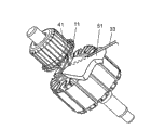
图2示出图1所示的整流式电动机的电枢的侧视图。FIG. 2 shows a side view of an armature of the commutator motor shown in FIG. 1 .
图3示出说明本发明的连接导线的主要部分的外观。Fig. 3 shows the appearance of main parts illustrating the connecting wire of the present invention.
图4、5和6示意性地说明与图3所示的进行比较的图。Figures 4, 5 and 6 schematically illustrate diagrams for comparison with those shown in Figure 3 .
图7说明本发明的导线连接。Figure 7 illustrates the wire connection of the present invention.
图8和9示意性地说明与图7所示的进行比较的图。8 and 9 schematically illustrate graphs for comparison with those shown in FIG. 7 .
图10-图13示出本发明的卷绕步骤的一部分并图示说明卷绕的结束。Figures 10-13 show part of the winding steps of the present invention and illustrate the end of winding.
图14-图16示出本发明的卷绕步骤的一部分并图示说明卷绕的开始。Figures 14-16 show part of the winding steps of the present invention and illustrate the start of winding.
图17示出本发明的再次压配合步骤的一部分的侧视图。Figure 17 shows a side view of a part of the re-press fit step of the present invention.
图18示出说明常规导线连接(α-形钩固定方法)的局部外观。Fig. 18 shows a partial appearance illustrating conventional wire connection (α-shaped hook fixing method).
图19示出说明常规导线连接(U-形钩固定方法)的局部外观。Fig. 19 shows a partial appearance illustrating conventional wire connection (U-shaped hook fixing method).
图20示出说明常规连接导线方法(短α-形)的剖面图。Fig. 20 shows a sectional view illustrating a conventional method of connecting wires (short α-shape).
图21示出说明常规连接导线方法(长α-形)的剖面图。Fig. 21 shows a sectional view illustrating a conventional method of connecting wires (long α-shape).
具体实施方式 Detailed ways
下面参照附图描述本发明的实施例。图1示出本发明的整体结构。图1中,通过为场磁心2提供场磁铁绕组3而形成场磁铁1。电枢10是这样形成的:通过为固定到转动轴11的电枢铁芯12提供电枢绕组13,并在轴11上安装整流器40,然后由设置在转动轴11的两端上的轴承5可旋转地支撑。Embodiments of the present invention are described below with reference to the drawings. Figure 1 shows the overall structure of the present invention. In FIG. 1 , a
场磁铁1固定到托架22上,并且一对碳刷(未示出)用螺钉24经由刷架23固定到托架22。转动轴11装备有旋转式风扇17,并且导气装置18布置在风扇17周围和下方以形成空气通道。The
当给上述结构供电时,从场磁铁绕组3提供的电流通过碳刷(未示出)流到整流器40。在由场磁心2产生的磁通量和电枢绕组13上的电流之间产生力,从而使电枢10转动。电枢10的转动使风扇17旋转,因此从吸口25吸入的空气沿箭头标记行进,从而在空气从托架22的排气口26排出之前冷却电枢10、场磁铁1和碳刷。When power is supplied to the above structure, the current supplied from the field magnet winding 3 flows to the
图2详细示出本发明图1描述的电枢10。电枢铁芯12和整流器40通过压配合或收缩配合(shrink-fitting)方法连接在转动轴11上。电枢铁芯12卷绕有电枢绕组13,其经由连接导线部分31联接到整流器40的钩41上。术语“电枢绕组”在下文中用于区别场磁铁绕组,否则,其简称为“绕组”。FIG. 2 shows in detail the
图3详细示出本发明实施例的主要部分。图4、5及6示出与图3示出的根据本发明实施例的比较。它们示出图2中所示的连接导线部分31的卷绕过程。图3和4说明开放的短α-形连接导线方法,图5说明常规的短α-形连接导线方法,图6说明长α-形连接导线方法。电枢铁芯12具有12个槽14,并且绕组13以分布卷绕方式卷绕。整流器40具有24个整流片,每一个整流片配备有用于连接到一连接导线末端的钩41。Fig. 3 shows the main part of the embodiment of the present invention in detail. 4 , 5 and 6 show a comparison with the embodiment according to the invention shown in FIG. 3 . They show the winding process of the connecting
具有偶数个槽的电枢铁芯经常采用双线锭方法(double flier method)进行卷绕,即,彼此面对的一对绕组依次联接到整流器的钩上,并且同时,在电枢铁芯的槽处连续地卷绕在电枢铁芯上,从而形成电枢绕组。图3中,联接到整流器钩41的导线32形成连接导线33并且行进至一对槽14,然后导线32在槽14上被卷绕多匝,从而形成绕组13,然后形成连接导线34并联接到相邻的下一钩41。当导线34联接到钩41时,它沿转动轴11弯曲并成形,因此形成图3示出的弯曲部分15。Armature cores with an even number of slots are often wound using the double flier method, that is, a pair of windings facing each other are sequentially coupled to the hooks of the commutator, and at the same time, The slots are wound continuously around the armature core to form the armature winding. In Fig. 3, the
如果连接导线没有弯曲,如图4所示导线34A在空中平直伸展,因此导线34A阻挡下一绕组13A在导线34A内侧卷绕。结果,绕组13A没有充分地容纳在槽14中,或线圈端35A在整流器附近变得异常高。If the connecting wire is not bent, the wire 34A stretches straight in the air as shown in FIG. 4 , so the wire 34A blocks the next winding 13A from winding inside the wire 34A. As a result, the winding 13A is not sufficiently accommodated in the
如图5所示,连接导线33B和34B通过常规的短α-形方法在空中平直伸展,使得下一绕组被这些连接导线所阻挡,如图4所示。如图6所示,连接导线33C、34C通过长α-形方法围绕转动轴11卷绕,使得线圈端35C在整流器附近变厚。As shown in FIG. 5, the connecting
图7示出根据该实施例的导线连接。图8和9示出与图7所示的进行比较。图8示出对应于图5所示的常规短α-形方法,图9示出对应于图6所示的长α-形方法。FIG. 7 shows wire connections according to this embodiment. 8 and 9 show a comparison with that shown in FIG. 7 . FIG. 8 shows a conventional short α-shape method corresponding to that shown in FIG. 5 , and FIG. 9 shows a long α-shape method corresponding to that shown in FIG. 6 .
图7、8和9所示的导线连接用于具有带有两极、12个槽的电枢铁芯12和24个片的整流器40的电动机中。整流片的数量是槽的数量的整数倍。在那些附图中,每个附图的上部示出的“带”是整流器40的展开,该展开表示24个钩。每个附图的下部示出的“方块”是芯的槽14,并且所述方块示出12个槽的位置。图7中,卷绕以标记有“开始”的第11号钩开始,并且形成沿箭头标记A行进的连接导线33,然后进入第1号槽,导线将卷绕在该槽上,并且在两个槽(第1号槽和第6号槽)上卷绕多匝。然后导线形成连接导线34并连接到第10号钩,并在连接到第9号钩之前再次在第1号槽和第6号槽上卷绕。然后,导线行进通过第12号槽并在第12号槽和第5号槽上卷绕。导线向前重复与上述步骤类似的步骤。The wire connections shown in Figures 7, 8 and 9 are used in a motor having a two-pole, 12-
图8示出与图7示出的导线连接进行比较的导线连接。卷绕以连接到标记有“开始”的第23号钩为开始,然后形成连接导线33B并且行进到第1号槽中,并且在两个槽(即,第1号槽和第6号槽)上卷绕多匝。导线形成行进到第22号钩的连接导线34B,并连接到第22号钩,然后在连接到第21号钩之前再次在第1号槽和第6号槽上卷绕。然后导线行进到第12号槽,并在第12号槽和第5号槽上卷绕。导线向前重复与上述步骤类似的步骤。FIG. 8 shows a wire connection compared to the wire connection shown in FIG. 7 . The winding begins with connection to hook No. 23 marked "START", then forms connecting
图9也示出与图7示出的导线连接进行比较的导线连接。卷绕以连接到标记有“开始”的第11号钩为开始,然后形成连接导线33C并行进到第1号槽中,并且在两个槽(即,第1号槽和第6号槽)上卷绕多匝。导线形成沿箭头标记A行进到第10号钩的连接导线34C,并且连接到第10号钩,然后再次在第1号槽和第6号槽上卷绕,并沿箭头标记B行进并连接到第9号钩。导线然后行进到第12号槽,并在第12号槽和第5号槽上卷绕。导线向前重复与上述步骤类似的步骤。FIG. 9 also shows a wire connection for comparison with the wire connection shown in FIG. 7 . Winding begins with connection to hook No. 11 marked "START", then forms connecting
在交流电动机中,图8示出的常规短α-形方法的导线连接与图9示出的长α-形方法的导线连接等效。图7示出的根据该实施例的开放短α-形是半常规短α-形和半长α-形,即,它获取了这两种方法的优点。更具体的,开放短α-形方法采用和长α-形方法相同的钩和槽之间的位置关系,但采用不同的连接导线路径,即导线沿最短路径行进,从而连接导线紧密地沿转动轴行进。结果,连接导线不阻挡绕组,这就是长α-形方法的优点,并且卷绕的开始和结束中之一利用了该优点。In an AC motor, the wire connection of the conventional short α-shape method shown in FIG. 8 is equivalent to the wire connection of the long α-shape method shown in FIG. 9 . The open short α-shape according to this embodiment shown in FIG. 7 is a semi-regular short α-shape and a semi-long α-shape, ie it captures the advantages of both approaches. More specifically, the open short α-shape method uses the same positional relationship between the hook and the slot as the long α-shape method, but uses a different connecting wire path, that is, the wire travels along the shortest path so that the connecting wire closely follows the rotational Axis travel. As a result, the connecting wires do not block the winding, which is the advantage of the long α-shape method, and one of the beginning and the end of the winding takes advantage of this advantage.
下面研究连接导线的总长度。连接导线表示在将被连接的钩和将被卷绕的槽之间延伸的导线,并且这里的主题是如何缩短连接导线的总长度。Next, consider the total length of the connecting wires. The connection wire refers to the wire extending between the hook to be connected and the groove to be wound, and the subject here is how to shorten the total length of the connection wire.
在图8示出的常规短α-形的情况下,每个连接导线33B和34B的长度的总和为总长度。这种情况下,导线从导线所连接到的钩经由最短路径行进到供导线卷绕的槽。因此,总长度与其它情况相比是最短的。In the case of the conventional short α-shape shown in FIG. 8, the sum of the lengths of each of the
在图9示出的长α-形的情况下,每个连接导线33C和34C的长度的总和是总长度。这种情况下,导线从导线所连接到的钩经由最长路径行进到供导线卷绕的槽。因此,总长度与其它情况相比是最长的。In the case of the long α-shape shown in FIG. 9, the sum of the lengths of each of the
在图7示出的该实施例的情况下,每个连接导线33和34的长度的总和为总长度。该情况看上去有些像常规短α-形;但是,在该实施例中,钩和槽之间的距离比常规短α-形的长,然而,这个情况具有作为本发明特征的弯曲部分。总长度因此变得比图8示出的常规短α-形的总长度长,但比图9示出的长α-形的总长度短。In the case of the embodiment shown in FIG. 7, the sum of the lengths of each connecting
在相比其他类型的电动机具有最长的线圈端的两极电动机的情况下,如果两极电动机采用长α-形,则连接导线在整流器附近沿线圈端35C行进以作导线连接,使得导线的长度变得非常长,这对铜损产生不利影响。因此,采用本发明的开放短α-形极大地提高了电动机的效率。In the case of a two-pole motor having the longest coil ends compared to other types of motors, if the two-pole motor adopts a long α-shape, the connection wire runs along the
解决由长连接导线引起的问题最终降低了整流器和更接近整流器的芯端部之间的线圈端的体积,并允许形成整流器附近的线圈端的体积最小的电枢绕组。开放短α-形的弯曲的连接导线在钩和弯曲点15之间平直伸展,使得整流器40下部变得完全开放。在卷绕步骤后,这个开放空间允许进行缩短整流器和芯之间的距离的另一处理,因此电枢的尺寸可以减小。Solving the problems caused by long connecting wires ultimately reduces the volume of the coil end between the rectifier and the core end closer to the rectifier and allows the formation of a minimal volume armature winding for the coil end near the rectifier. The open short α-shaped bent connecting wire runs straight between the hook and the
弯曲成形的部分比整流器具有更小的外径,并且因此可以用绳将该弯曲成形的部分绑扎在转动轴上,从而防止该弯曲部分在下文描述的再次压配合步骤中变形。The bent portion has a smaller outer diameter than the commutator, and thus can be tied to the rotating shaft with a string, thereby preventing the bent portion from being deformed in a press-fitting step described below again.
开放短α-形在线圈端上方产生空间,因此可以进一步堆积芯板,因而电枢铁芯12的叠片可增厚以获得更高效率。结果,可获得更高效率的电动机,而无需增加沿着轴的外部尺寸。The open short α-shape creates space above the coil ends so that further core plates can be stacked and thus the laminations of the
图3示出当绕组13的末端连接到钩41时形成的较短的连接导线34的例子;然而,存在导线连接的另一规格,即,当绕组的开始行进到其上卷绕导线的槽14时形成较短的连接导线33。在这种情况下,当导线33在连接到钩41以后向绕组位置移动时,连接导线33在卷绕步骤开始之前弯曲并成形,因此可获得与前述相似的优点。Figure 3 shows an example of a shorter connecting
上述讨论证明,本发明解决了由常规导线连接方法,例如在用于真空吸尘器的微型整流式电动机的电枢绕组中使用的长α形和短α形,所引起的导线连接问题,并且使整流器附近的线圈端的体积下降。因此可以减少电枢的铜损,从而可得到更高效率的微型整流式电动机。The above discussion proves that the present invention solves the wire connection problems caused by conventional wire connection methods, such as the long alpha and short alpha shapes used in the armature windings of miniature commutator motors for vacuum cleaners, and makes the rectifier The volume near the coil ends drops. Therefore, the copper loss of the armature can be reduced, so that a more efficient micro-commutator motor can be obtained.
下面说明制造上述弯曲且成形的连接导线的方法。图10-13示出弯曲并成形绕组末端以形成连接导线的各个步骤的外视图。省略了阻挡外视图展示的与成形装置(被称作“成形器(former)”)相关的部件。Next, a method of manufacturing the above-mentioned bent and shaped connecting wire will be described. 10-13 show external views of the various steps of bending and shaping the winding ends to form connecting wires. Components related to the forming device (referred to as "former") that obstruct the presentation of the external view are omitted.
图10示出从绕组13在槽上完成卷绕的位置旋转到导线将要钩在钩41上的位置的电枢铁芯12。从线锭继续的形成绕组末端的连接导线34沿线圈端35和转动轴11定位。图11示出将要用于成形连接导线的成形器51前进并朝着转动轴11推动连接导线34。在这种状态下,对弯曲导线21的极大的压力不会被施加在连接导线34上。FIG. 10 shows the
图12示出通过移动线锭使导线21钩在钩41上。在这种状态下,由成形器51弯曲连接导线34;然而,连接导线34只是沿成形器51弯曲并移动,因此用于形成弯曲部分的极大压力未施加在导线34上。图13示出通过转动线锭使连接导线34在钩41上形成α-形导线连接。钩在钩41上的导线21由钩41的边缘来弯曲,因此导线21稳定地定位于此。因此,在导线34经受下一步骤之前,成形器51的去除仍然使连接导线34保持按照原样弯曲。Fig. 12 shows that the
图14-16示出说明使由绕组开始形成的连接导线弯曲的各个卷绕步骤的外视图。省略了阻挡外视图展示的与成形器相关的部件。图14示出导线33卷绕在一对槽上,然后钩在钩41上。电枢铁芯12转动到将要卷绕下一绕组的另一对槽处。14-16 show external views illustrating the individual winding steps for bending the connecting wires initially formed by the winding. Parts related to the former that obstruct the presentation of the external view are omitted. FIG. 14 shows that the
图15示出将要用于成形连接导线的成形器51前进并且将连接导线33向转动轴11推动。这样的状态通过与线锭的转动同步而达到,并且形成弯曲部分的极大的载荷没有施加到导线33上。FIG. 15 shows that the shaper 51 to be used to shape the connecting wire advances and pushes the connecting
图16示出去掉成形器51的状态。当由线锭的转动将导线引入一对槽中时,连接导线33固定,使得即使去掉成形器51,已经受弯曲和成形处理的连接导线33也保持原样(弯曲且成形),并且进入下一卷绕步骤。FIG. 16 shows a state where the former 51 is removed. When the wire is introduced into a pair of grooves by the rotation of the wire ingot, the connecting
如上所述,该实施例的步骤不损坏连接导线并且容易形成弯曲部分,因此连接导线不阻挡下一绕组,因此线圈端的体积可以最小。As described above, the steps of this embodiment do not damage the connecting wire and easily form the bent portion, so the connecting wire does not block the next winding, so the volume of the coil end can be minimized.
图17示出说明在整流器附近形成线圈端的步骤和整流器再次压配合到最终位置的步骤的局部侧视图。省略了阻挡外视图展示的与夹具有关的部件。Figure 17 shows a partial side view illustrating the steps of forming the coil ends adjacent to the rectifier and the step of press fitting the rectifier again into its final position. Parts related to the clamp that obstruct the presentation of the external view are omitted.
为了使整流式电动机的尺寸减小,整流器40和电枢铁芯12之间的空间必须足够短以容纳线圈体积。在绕组中,整流器40和电枢铁芯12之间的空间加宽,并且在卷绕后,整流器40被再次压配合到其最终位置,从而可以确保产品的尺寸。下面说明在规定的尺寸中容纳线圈端的步骤,由于绕组的匝数导致线圈端突起。同时,说明再次压配合整流器40的步骤。In order to reduce the size of a commutated motor, the space between the
图17中,为成形所述连接导线而使用的夹具52插入到整流器40和线圈端35之间的空间中,以便可以维持连接导线的弯曲和成形的状态。同时,夹具52形成为适合于弯曲的连接导线的形状。然后夹具52将线圈端35向电枢铁芯12推动,同时,整流器挤压夹具53挤压整流器40以再次压配合到它的最终位置。维持连接导线的弯曲和成形的状态可以防止钩在钩41上的导线变形,并且成形线圈端35和再次压配合整流器40两者同时执行。同时进行这些动作是重要的,因为如果成形线圈端35在再次压配合之前执行,则钩在钩41上的导线受到拉伸,这会引起严重的缺陷,例如连接部处的导线拉断。In FIG. 17, a
上述讨论的步骤可以维持钩41和弯曲的连接导线之间的关系,直到电动机完全装配好,从而维持了钩和已经受连接导线处理的绕组之间的连接,并且由此确保电动机的质量。The above-discussed steps maintain the relationship between the
工业应用性Industrial applicability
本发明的整流式电动机与短α-形导线连接或长α-形导线连接相比可以使用尺寸大大减小的线圈端体积,而能够更有效地完成对电动机的绕线操作。该结构允许减少电枢的铜损,因此可获得尺寸减小且效率高的整流式电动机。The commutated motor of the present invention can use a greatly reduced size coil end volume as compared to a short alpha-wire connection or a long alpha-wire connection, enabling more efficient winding of the motor. This structure allows reducing the copper loss of the armature, so that a commutated motor with reduced size and high efficiency can be obtained.
附图中的附图标记Reference signs in the drawings
1定子1 stator
2场磁心2 field cores
3场磁铁绕组3 Field Magnet Windings
10转子10 rotors
11转动轴11 axis of rotation
12电枢铁芯12 armature core
13电枢绕组13 armature winding
14槽14 slots
33,34连接导线33, 34 connecting wire
40整流器40 rectifier
41钩41 hooks
51用于成形连接导线的成形器51 Shapers for shaping connecting wires
52用于成形绕组的夹具52 Fixtures for forming windings
53整流器挤压夹具53 rectifier extrusion fixture
Claims (7)
Applications Claiming Priority (2)
| Application Number | Priority Date | Filing Date | Title |
|---|---|---|---|
| JP342206/2004 | 2004-11-26 | ||
| JP2004342206 | 2004-11-26 |
Publications (2)
| Publication Number | Publication Date |
|---|---|
| CN101040420A CN101040420A (en) | 2007-09-19 |
| CN100593278C true CN100593278C (en) | 2010-03-03 |
Family
ID=36051136
Family Applications (1)
| Application Number | Title | Priority Date | Filing Date |
|---|---|---|---|
| CN200580034518A Expired - Lifetime CN100593278C (en) | 2004-11-26 | 2005-11-25 | Commutator motor manufacturing method |
Country Status (5)
| Country | Link |
|---|---|
| US (1) | US20080054752A1 (en) |
| EP (1) | EP1815581A1 (en) |
| JP (1) | JP4623094B2 (en) |
| CN (1) | CN100593278C (en) |
| WO (1) | WO2006057449A1 (en) |
Families Citing this family (5)
| Publication number | Priority date | Publication date | Assignee | Title |
|---|---|---|---|---|
| JP5122914B2 (en) * | 2007-10-30 | 2013-01-16 | マブチモーター株式会社 | Brushed DC motor and method for manufacturing the same |
| KR101345501B1 (en) * | 2010-01-20 | 2013-12-27 | 미쓰비시덴키 가부시키가이샤 | Rotating electrical machine and manufacturing method of the same |
| CN101888154A (en) * | 2010-05-07 | 2010-11-17 | 许晓华 | Embedded groove type rotor winding device |
| CN103427579B (en) * | 2012-05-15 | 2015-10-07 | 深圳联和电机有限公司 | The manufacture method of permanent magnet direct current motor and rotor assembly thereof |
| EP2980971B1 (en) * | 2013-03-26 | 2020-04-22 | Mitsuba Corporation | Electric motor |
Citations (5)
| Publication number | Priority date | Publication date | Assignee | Title |
|---|---|---|---|---|
| US2381533A (en) * | 1943-12-30 | 1945-08-07 | Independent Pneumatic Tool Co | Motor armature |
| EP0058351A1 (en) * | 1981-02-13 | 1982-08-25 | Siemens Aktiengesellschaft | Connecting device for the beginnings and ends of the coils of an induction motor rotor winding |
| EP0119172A2 (en) * | 1983-03-08 | 1984-09-19 | OFFICINE MECCANICHE PAVESI & C. S.p.A. | Device for forming the rotor winding coils of a dynamoelectric machine and for anchoring the ends of the coils to a commutator associated with the rotor |
| EP1091473A2 (en) * | 1999-10-04 | 2001-04-11 | Asmo Co., Ltd. | Commutator of an electric motor |
| US20040017124A1 (en) * | 2000-06-14 | 2004-01-29 | Wang Ren Hong | Motor armature having distributed windings for reducing arcing |
Family Cites Families (18)
| Publication number | Priority date | Publication date | Assignee | Title |
|---|---|---|---|---|
| US3471731A (en) * | 1967-06-13 | 1969-10-07 | Millers Falls Co | Armature |
| US3973738A (en) * | 1969-10-15 | 1976-08-10 | The Globe Tool And Engineering Company | Armature winding and leading connecting machine |
| US3705459A (en) * | 1971-06-24 | 1972-12-12 | Globe Tool Eng Co | Wave winding of armatures |
| DE2310380B2 (en) * | 1973-03-02 | 1976-05-20 | Robert Bosch Gmbh, 7000 Stuttgart | DC MOTOR |
| US4417388A (en) * | 1980-11-28 | 1983-11-29 | Allied Corporation | Method of making a multiple open turn lap wound dynamoelectric machine |
| JPS59107574U (en) * | 1982-12-29 | 1984-07-19 | マブチモ−タ−株式会社 | Commutator device for small motors |
| US4541170A (en) * | 1984-03-08 | 1985-09-17 | Officine Meccaniche Pavesi & C. S.P.A. | Method and device for forming the rotor winding coils of a dynamoelectric machine |
| US4707629A (en) * | 1986-03-24 | 1987-11-17 | Wasko George J | Rotary converter having dual-winding rotor |
| NL8902180A (en) * | 1989-08-29 | 1991-03-18 | Philips Nv | METHOD FOR DEVELOPING AN ANCHOR BODY FROM AN ANCHOR AND ELECTRICAL MACHINE EQUIPPED WITH AN ANCHOR MADE ACCORDING TO THE METHOD |
| US5122975A (en) * | 1989-11-30 | 1992-06-16 | Axis Usa, Inc. | Methods and apparatus for marking and identifying hooks of electric motors |
| DE9007029U1 (en) * | 1990-06-23 | 1991-10-24 | Robert Bosch Gmbh, 70469 Stuttgart | Armature for high-speed electric motors with forced ventilation in air containing abrasive dust |
| GB9206637D0 (en) * | 1992-03-26 | 1992-05-06 | Watliff Co Ltd | Armature |
| WO1994027501A1 (en) * | 1993-05-24 | 1994-12-08 | Boston Scientific Corporation | Medical acoustic imaging catheter and guidewire |
| US5470615A (en) * | 1994-03-11 | 1995-11-28 | Axis Usa, Inc. | Bonding and coating methods and apparatus for th coils of dynamo-electric machine parts |
| JPH1127907A (en) * | 1997-07-07 | 1999-01-29 | Matsushita Electric Ind Co Ltd | Method of manufacturing commutator motor |
| JP2002517154A (en) * | 1998-05-28 | 2002-06-11 | ローベルト ボツシユ ゲゼルシヤフト ミツト ベシユレンクテル ハフツング | Rotor for electric motor and method for manufacturing the rotor |
| US7274126B2 (en) * | 2000-06-14 | 2007-09-25 | Black & Decker Inc. | Motor armature having distributed windings for reducing arcing |
| US6703754B1 (en) * | 2001-10-01 | 2004-03-09 | Ametek, Inc. | Electric motor and brush retaining assembly |
-
2005
- 2005-11-25 CN CN200580034518A patent/CN100593278C/en not_active Expired - Lifetime
- 2005-11-25 JP JP2007513510A patent/JP4623094B2/en not_active Expired - Lifetime
- 2005-11-25 EP EP05811453A patent/EP1815581A1/en not_active Withdrawn
- 2005-11-25 US US11/576,570 patent/US20080054752A1/en not_active Abandoned
- 2005-11-25 WO PCT/JP2005/022135 patent/WO2006057449A1/en not_active Ceased
Patent Citations (5)
| Publication number | Priority date | Publication date | Assignee | Title |
|---|---|---|---|---|
| US2381533A (en) * | 1943-12-30 | 1945-08-07 | Independent Pneumatic Tool Co | Motor armature |
| EP0058351A1 (en) * | 1981-02-13 | 1982-08-25 | Siemens Aktiengesellschaft | Connecting device for the beginnings and ends of the coils of an induction motor rotor winding |
| EP0119172A2 (en) * | 1983-03-08 | 1984-09-19 | OFFICINE MECCANICHE PAVESI & C. S.p.A. | Device for forming the rotor winding coils of a dynamoelectric machine and for anchoring the ends of the coils to a commutator associated with the rotor |
| EP1091473A2 (en) * | 1999-10-04 | 2001-04-11 | Asmo Co., Ltd. | Commutator of an electric motor |
| US20040017124A1 (en) * | 2000-06-14 | 2004-01-29 | Wang Ren Hong | Motor armature having distributed windings for reducing arcing |
Also Published As
| Publication number | Publication date |
|---|---|
| WO2006057449A1 (en) | 2006-06-01 |
| CN101040420A (en) | 2007-09-19 |
| JP4623094B2 (en) | 2011-02-02 |
| US20080054752A1 (en) | 2008-03-06 |
| EP1815581A1 (en) | 2007-08-08 |
| JP2008516569A (en) | 2008-05-15 |
Similar Documents
| Publication | Publication Date | Title |
|---|---|---|
| US7619344B2 (en) | Armature of rotary electric machine and manufacturing method thereof | |
| CN1323482C (en) | Brushless motor and sealed compressor having same | |
| US7049725B2 (en) | Dynamoelectric machine stator and method for mounting prewound coils thereunto | |
| US6476530B1 (en) | Stator of alternator for use in automotive vehicle | |
| US8125117B2 (en) | Electric motor and rotor therefor | |
| KR102716136B1 (en) | Electric motor with a stator formed from a pole chain and with contactless routing of enameled aluminum wire | |
| JP6107386B2 (en) | Motor and compressor | |
| EP1717934A3 (en) | Motor and method for manufacturing the motor | |
| JP5523318B2 (en) | 3-phase DC motor | |
| CN102738917B (en) | Electric motor and motor-driven compressor using same | |
| CN100593278C (en) | Commutator motor manufacturing method | |
| US8946965B2 (en) | Armature of electric motor and electric motor | |
| KR20150024181A (en) | A motor coil winding method consisting of a distributed winding | |
| CN112436641A (en) | Stator module, motor, compressor and refrigeration equipment | |
| US20070024146A1 (en) | Single-phase motor and stator winding method thereof | |
| JP2001292544A5 (en) | ||
| KR102476318B1 (en) | Armature coil winding method of DC motor | |
| JP4084083B2 (en) | Method and apparatus for winding stator core | |
| JP2008099416A (en) | Armature for motor, motor, and winding method of armature for motor | |
| KR200402555Y1 (en) | The winding structure for a stator coil of brushless motor | |
| JP3296681B2 (en) | Commutator motor | |
| JP2003333809A5 (en) | ||
| EP3739735B1 (en) | Motor | |
| JP2013146146A (en) | Commutator motor | |
| JPH09271157A (en) | Method of manufacturing cup-shaped multiple ironless armature coil |
Legal Events
| Date | Code | Title | Description |
|---|---|---|---|
| C06 | Publication | ||
| PB01 | Publication | ||
| C10 | Entry into substantive examination | ||
| SE01 | Entry into force of request for substantive examination | ||
| C14 | Grant of patent or utility model | ||
| GR01 | Patent grant | ||
| CX01 | Expiry of patent term | ||
| CX01 | Expiry of patent term |
Granted publication date: 20100303 |