CN100577995C - Honeycomb structure and exhaust gas purifying device - Google Patents
Honeycomb structure and exhaust gas purifying device Download PDFInfo
- Publication number
- CN100577995C CN100577995C CN200580000312A CN200580000312A CN100577995C CN 100577995 C CN100577995 C CN 100577995C CN 200580000312 A CN200580000312 A CN 200580000312A CN 200580000312 A CN200580000312 A CN 200580000312A CN 100577995 C CN100577995 C CN 100577995C
- Authority
- CN
- China
- Prior art keywords
- honeycomb structure
- holes
- volume
- cross
- structure according
- Prior art date
- Legal status (The legal status is an assumption and is not a legal conclusion. Google has not performed a legal analysis and makes no representation as to the accuracy of the status listed.)
- Expired - Lifetime
Links
Images







Classifications
-
- F—MECHANICAL ENGINEERING; LIGHTING; HEATING; WEAPONS; BLASTING
- F01—MACHINES OR ENGINES IN GENERAL; ENGINE PLANTS IN GENERAL; STEAM ENGINES
- F01N—GAS-FLOW SILENCERS OR EXHAUST APPARATUS FOR MACHINES OR ENGINES IN GENERAL; GAS-FLOW SILENCERS OR EXHAUST APPARATUS FOR INTERNAL-COMBUSTION ENGINES
- F01N3/00—Exhaust or silencing apparatus having means for purifying, rendering innocuous, or otherwise treating exhaust
- F01N3/02—Exhaust or silencing apparatus having means for purifying, rendering innocuous, or otherwise treating exhaust for cooling, or for removing solid constituents of, exhaust
- F01N3/021—Exhaust or silencing apparatus having means for purifying, rendering innocuous, or otherwise treating exhaust for cooling, or for removing solid constituents of, exhaust by means of filters
- F01N3/022—Exhaust or silencing apparatus having means for purifying, rendering innocuous, or otherwise treating exhaust for cooling, or for removing solid constituents of, exhaust by means of filters characterised by specially adapted filtering structure, e.g. honeycomb, mesh or fibrous
- F01N3/0222—Exhaust or silencing apparatus having means for purifying, rendering innocuous, or otherwise treating exhaust for cooling, or for removing solid constituents of, exhaust by means of filters characterised by specially adapted filtering structure, e.g. honeycomb, mesh or fibrous the structure being monolithic, e.g. honeycombs
-
- B—PERFORMING OPERATIONS; TRANSPORTING
- B01—PHYSICAL OR CHEMICAL PROCESSES OR APPARATUS IN GENERAL
- B01D—SEPARATION
- B01D39/00—Filtering material for liquid or gaseous fluids
- B01D39/14—Other self-supporting filtering material ; Other filtering material
- B01D39/20—Other self-supporting filtering material ; Other filtering material of inorganic material, e.g. asbestos paper, metallic filtering material of non-woven wires
-
- B—PERFORMING OPERATIONS; TRANSPORTING
- B01—PHYSICAL OR CHEMICAL PROCESSES OR APPARATUS IN GENERAL
- B01D—SEPARATION
- B01D46/00—Filters or filtering processes specially modified for separating dispersed particles from gases or vapours
- B01D46/24—Particle separators, e.g. dust precipitators, using rigid hollow filter bodies
- B01D46/2403—Particle separators, e.g. dust precipitators, using rigid hollow filter bodies characterised by the physical shape or structure of the filtering element
- B01D46/2418—Honeycomb filters
- B01D46/2425—Honeycomb filters characterized by parameters related to the physical properties of the honeycomb structure material
-
- B—PERFORMING OPERATIONS; TRANSPORTING
- B01—PHYSICAL OR CHEMICAL PROCESSES OR APPARATUS IN GENERAL
- B01D—SEPARATION
- B01D46/00—Filters or filtering processes specially modified for separating dispersed particles from gases or vapours
- B01D46/24—Particle separators, e.g. dust precipitators, using rigid hollow filter bodies
- B01D46/2403—Particle separators, e.g. dust precipitators, using rigid hollow filter bodies characterised by the physical shape or structure of the filtering element
- B01D46/2418—Honeycomb filters
- B01D46/2425—Honeycomb filters characterized by parameters related to the physical properties of the honeycomb structure material
- B01D46/2429—Honeycomb filters characterized by parameters related to the physical properties of the honeycomb structure material of the honeycomb walls or cells
-
- B—PERFORMING OPERATIONS; TRANSPORTING
- B01—PHYSICAL OR CHEMICAL PROCESSES OR APPARATUS IN GENERAL
- B01D—SEPARATION
- B01D46/00—Filters or filtering processes specially modified for separating dispersed particles from gases or vapours
- B01D46/24—Particle separators, e.g. dust precipitators, using rigid hollow filter bodies
- B01D46/2403—Particle separators, e.g. dust precipitators, using rigid hollow filter bodies characterised by the physical shape or structure of the filtering element
- B01D46/2418—Honeycomb filters
- B01D46/2425—Honeycomb filters characterized by parameters related to the physical properties of the honeycomb structure material
- B01D46/24491—Porosity
-
- B—PERFORMING OPERATIONS; TRANSPORTING
- B01—PHYSICAL OR CHEMICAL PROCESSES OR APPARATUS IN GENERAL
- B01D—SEPARATION
- B01D46/00—Filters or filtering processes specially modified for separating dispersed particles from gases or vapours
- B01D46/24—Particle separators, e.g. dust precipitators, using rigid hollow filter bodies
- B01D46/2403—Particle separators, e.g. dust precipitators, using rigid hollow filter bodies characterised by the physical shape or structure of the filtering element
- B01D46/2418—Honeycomb filters
- B01D46/2425—Honeycomb filters characterized by parameters related to the physical properties of the honeycomb structure material
- B01D46/24492—Pore diameter
-
- B—PERFORMING OPERATIONS; TRANSPORTING
- B01—PHYSICAL OR CHEMICAL PROCESSES OR APPARATUS IN GENERAL
- B01D—SEPARATION
- B01D46/00—Filters or filtering processes specially modified for separating dispersed particles from gases or vapours
- B01D46/24—Particle separators, e.g. dust precipitators, using rigid hollow filter bodies
- B01D46/2403—Particle separators, e.g. dust precipitators, using rigid hollow filter bodies characterised by the physical shape or structure of the filtering element
- B01D46/2418—Honeycomb filters
- B01D46/2451—Honeycomb filters characterized by the geometrical structure, shape, pattern or configuration or parameters related to the geometry of the structure
-
- B—PERFORMING OPERATIONS; TRANSPORTING
- B01—PHYSICAL OR CHEMICAL PROCESSES OR APPARATUS IN GENERAL
- B01D—SEPARATION
- B01D46/00—Filters or filtering processes specially modified for separating dispersed particles from gases or vapours
- B01D46/24—Particle separators, e.g. dust precipitators, using rigid hollow filter bodies
- B01D46/2403—Particle separators, e.g. dust precipitators, using rigid hollow filter bodies characterised by the physical shape or structure of the filtering element
- B01D46/2418—Honeycomb filters
- B01D46/2451—Honeycomb filters characterized by the geometrical structure, shape, pattern or configuration or parameters related to the geometry of the structure
- B01D46/2455—Honeycomb filters characterized by the geometrical structure, shape, pattern or configuration or parameters related to the geometry of the structure of the whole honeycomb or segments
-
- B—PERFORMING OPERATIONS; TRANSPORTING
- B01—PHYSICAL OR CHEMICAL PROCESSES OR APPARATUS IN GENERAL
- B01D—SEPARATION
- B01D46/00—Filters or filtering processes specially modified for separating dispersed particles from gases or vapours
- B01D46/24—Particle separators, e.g. dust precipitators, using rigid hollow filter bodies
- B01D46/2403—Particle separators, e.g. dust precipitators, using rigid hollow filter bodies characterised by the physical shape or structure of the filtering element
- B01D46/2418—Honeycomb filters
- B01D46/2451—Honeycomb filters characterized by the geometrical structure, shape, pattern or configuration or parameters related to the geometry of the structure
- B01D46/247—Honeycomb filters characterized by the geometrical structure, shape, pattern or configuration or parameters related to the geometry of the structure of the cells
-
- B—PERFORMING OPERATIONS; TRANSPORTING
- B01—PHYSICAL OR CHEMICAL PROCESSES OR APPARATUS IN GENERAL
- B01D—SEPARATION
- B01D46/00—Filters or filtering processes specially modified for separating dispersed particles from gases or vapours
- B01D46/24—Particle separators, e.g. dust precipitators, using rigid hollow filter bodies
- B01D46/2403—Particle separators, e.g. dust precipitators, using rigid hollow filter bodies characterised by the physical shape or structure of the filtering element
- B01D46/2418—Honeycomb filters
- B01D46/2451—Honeycomb filters characterized by the geometrical structure, shape, pattern or configuration or parameters related to the geometry of the structure
- B01D46/2478—Structures comprising honeycomb segments
-
- B—PERFORMING OPERATIONS; TRANSPORTING
- B01—PHYSICAL OR CHEMICAL PROCESSES OR APPARATUS IN GENERAL
- B01D—SEPARATION
- B01D46/00—Filters or filtering processes specially modified for separating dispersed particles from gases or vapours
- B01D46/24—Particle separators, e.g. dust precipitators, using rigid hollow filter bodies
- B01D46/2403—Particle separators, e.g. dust precipitators, using rigid hollow filter bodies characterised by the physical shape or structure of the filtering element
- B01D46/2418—Honeycomb filters
- B01D46/2451—Honeycomb filters characterized by the geometrical structure, shape, pattern or configuration or parameters related to the geometry of the structure
- B01D46/2484—Cell density, area or aspect ratio
-
- B—PERFORMING OPERATIONS; TRANSPORTING
- B01—PHYSICAL OR CHEMICAL PROCESSES OR APPARATUS IN GENERAL
- B01D—SEPARATION
- B01D46/00—Filters or filtering processes specially modified for separating dispersed particles from gases or vapours
- B01D46/24—Particle separators, e.g. dust precipitators, using rigid hollow filter bodies
- B01D46/2403—Particle separators, e.g. dust precipitators, using rigid hollow filter bodies characterised by the physical shape or structure of the filtering element
- B01D46/2418—Honeycomb filters
- B01D46/2451—Honeycomb filters characterized by the geometrical structure, shape, pattern or configuration or parameters related to the geometry of the structure
- B01D46/2486—Honeycomb filters characterized by the geometrical structure, shape, pattern or configuration or parameters related to the geometry of the structure characterised by the shapes or configurations
-
- B—PERFORMING OPERATIONS; TRANSPORTING
- B01—PHYSICAL OR CHEMICAL PROCESSES OR APPARATUS IN GENERAL
- B01D—SEPARATION
- B01D46/00—Filters or filtering processes specially modified for separating dispersed particles from gases or vapours
- B01D46/24—Particle separators, e.g. dust precipitators, using rigid hollow filter bodies
- B01D46/2403—Particle separators, e.g. dust precipitators, using rigid hollow filter bodies characterised by the physical shape or structure of the filtering element
- B01D46/2418—Honeycomb filters
- B01D46/2451—Honeycomb filters characterized by the geometrical structure, shape, pattern or configuration or parameters related to the geometry of the structure
- B01D46/2486—Honeycomb filters characterized by the geometrical structure, shape, pattern or configuration or parameters related to the geometry of the structure characterised by the shapes or configurations
- B01D46/249—Quadrangular e.g. square or diamond
-
- B—PERFORMING OPERATIONS; TRANSPORTING
- B01—PHYSICAL OR CHEMICAL PROCESSES OR APPARATUS IN GENERAL
- B01D—SEPARATION
- B01D46/00—Filters or filtering processes specially modified for separating dispersed particles from gases or vapours
- B01D46/24—Particle separators, e.g. dust precipitators, using rigid hollow filter bodies
- B01D46/2403—Particle separators, e.g. dust precipitators, using rigid hollow filter bodies characterised by the physical shape or structure of the filtering element
- B01D46/2418—Honeycomb filters
- B01D46/2451—Honeycomb filters characterized by the geometrical structure, shape, pattern or configuration or parameters related to the geometry of the structure
- B01D46/2486—Honeycomb filters characterized by the geometrical structure, shape, pattern or configuration or parameters related to the geometry of the structure characterised by the shapes or configurations
- B01D46/2494—Octagonal
-
- B—PERFORMING OPERATIONS; TRANSPORTING
- B01—PHYSICAL OR CHEMICAL PROCESSES OR APPARATUS IN GENERAL
- B01D—SEPARATION
- B01D46/00—Filters or filtering processes specially modified for separating dispersed particles from gases or vapours
- B01D46/24—Particle separators, e.g. dust precipitators, using rigid hollow filter bodies
- B01D46/2403—Particle separators, e.g. dust precipitators, using rigid hollow filter bodies characterised by the physical shape or structure of the filtering element
- B01D46/2418—Honeycomb filters
- B01D46/2498—The honeycomb filter being defined by mathematical relationships
-
- B—PERFORMING OPERATIONS; TRANSPORTING
- B01—PHYSICAL OR CHEMICAL PROCESSES OR APPARATUS IN GENERAL
- B01J—CHEMICAL OR PHYSICAL PROCESSES, e.g. CATALYSIS OR COLLOID CHEMISTRY; THEIR RELEVANT APPARATUS
- B01J35/00—Catalysts, in general, characterised by their form or physical properties
- B01J35/50—Catalysts, in general, characterised by their form or physical properties characterised by their shape or configuration
- B01J35/56—Foraminous structures having flow-through passages or channels, e.g. grids or three-dimensional [3D] monoliths
- B01J35/57—Honeycombs
-
- B—PERFORMING OPERATIONS; TRANSPORTING
- B01—PHYSICAL OR CHEMICAL PROCESSES OR APPARATUS IN GENERAL
- B01D—SEPARATION
- B01D2279/00—Filters adapted for separating dispersed particles from gases or vapours specially modified for specific uses
- B01D2279/30—Filters adapted for separating dispersed particles from gases or vapours specially modified for specific uses for treatment of exhaust gases from IC Engines
-
- F—MECHANICAL ENGINEERING; LIGHTING; HEATING; WEAPONS; BLASTING
- F01—MACHINES OR ENGINES IN GENERAL; ENGINE PLANTS IN GENERAL; STEAM ENGINES
- F01N—GAS-FLOW SILENCERS OR EXHAUST APPARATUS FOR MACHINES OR ENGINES IN GENERAL; GAS-FLOW SILENCERS OR EXHAUST APPARATUS FOR INTERNAL-COMBUSTION ENGINES
- F01N2330/00—Structure of catalyst support or particle filter
- F01N2330/30—Honeycomb supports characterised by their structural details
- F01N2330/48—Honeycomb supports characterised by their structural details characterised by the number of flow passages, e.g. cell density
-
- F—MECHANICAL ENGINEERING; LIGHTING; HEATING; WEAPONS; BLASTING
- F01—MACHINES OR ENGINES IN GENERAL; ENGINE PLANTS IN GENERAL; STEAM ENGINES
- F01N—GAS-FLOW SILENCERS OR EXHAUST APPARATUS FOR MACHINES OR ENGINES IN GENERAL; GAS-FLOW SILENCERS OR EXHAUST APPARATUS FOR INTERNAL-COMBUSTION ENGINES
- F01N2340/00—Dimensional characteristics of the exhaust system, e.g. length, diameter or volume of the exhaust apparatus; Spatial arrangements of exhaust apparatuses
-
- Y—GENERAL TAGGING OF NEW TECHNOLOGICAL DEVELOPMENTS; GENERAL TAGGING OF CROSS-SECTIONAL TECHNOLOGIES SPANNING OVER SEVERAL SECTIONS OF THE IPC; TECHNICAL SUBJECTS COVERED BY FORMER USPC CROSS-REFERENCE ART COLLECTIONS [XRACs] AND DIGESTS
- Y02—TECHNOLOGIES OR APPLICATIONS FOR MITIGATION OR ADAPTATION AGAINST CLIMATE CHANGE
- Y02T—CLIMATE CHANGE MITIGATION TECHNOLOGIES RELATED TO TRANSPORTATION
- Y02T10/00—Road transport of goods or passengers
- Y02T10/10—Internal combustion engine [ICE] based vehicles
- Y02T10/12—Improving ICE efficiencies
-
- Y—GENERAL TAGGING OF NEW TECHNOLOGICAL DEVELOPMENTS; GENERAL TAGGING OF CROSS-SECTIONAL TECHNOLOGIES SPANNING OVER SEVERAL SECTIONS OF THE IPC; TECHNICAL SUBJECTS COVERED BY FORMER USPC CROSS-REFERENCE ART COLLECTIONS [XRACs] AND DIGESTS
- Y10—TECHNICAL SUBJECTS COVERED BY FORMER USPC
- Y10T—TECHNICAL SUBJECTS COVERED BY FORMER US CLASSIFICATION
- Y10T428/00—Stock material or miscellaneous articles
- Y10T428/24—Structurally defined web or sheet [e.g., overall dimension, etc.]
- Y10T428/24149—Honeycomb-like
Landscapes
- Physics & Mathematics (AREA)
- Geometry (AREA)
- Chemical & Material Sciences (AREA)
- Chemical Kinetics & Catalysis (AREA)
- Engineering & Computer Science (AREA)
- Mechanical Engineering (AREA)
- Combustion & Propulsion (AREA)
- General Engineering & Computer Science (AREA)
- Organic Chemistry (AREA)
- Materials Engineering (AREA)
- Life Sciences & Earth Sciences (AREA)
- Geology (AREA)
- Filtering Materials (AREA)
- Filtering Of Dispersed Particles In Gases (AREA)
- Catalysts (AREA)
- Exhaust Gas After Treatment (AREA)
- Processes For Solid Components From Exhaust (AREA)
Abstract
Description
技术领域 technical field
本申请以2004年2月23日申请的日本国发明专利申请2004-046949号作为在先申请并要求优先权。This application takes Japanese invention patent application No. 2004-046949 filed on February 23, 2004 as an earlier application and claims priority.
本发明涉及基于从柴油发动机等内燃机排出的废气中除去颗粒等的目的等而使用的蜂窝结构体以及废气净化装置。The present invention relates to a honeycomb structure and an exhaust gas purifying device used for the purpose of removing particles and the like from exhaust gas discharged from an internal combustion engine such as a diesel engine.
背景技术 Background technique
从巴士、卡车等车辆或施工机器等的内燃机排出的废气中含有颗粒,这些颗粒对环境、人体构成的危害已经成为了近来的一个问题。Particulates are contained in the exhaust gas discharged from internal combustion engines of vehicles such as buses and trucks, and construction equipment, and the harm of these particulates to the environment and human body has become a problem recently.
对此,提出了各种蜂窝结构体用作陶瓷过滤器,其使上述废气通过多孔质陶瓷以捕集废气中的颗粒,从而可以净化废气。In response to this, various honeycomb structures have been proposed as ceramic filters that can purify the exhaust gas by allowing the exhaust gas to pass through porous ceramics to trap particles in the exhaust gas.
以往,作为这种陶瓷过滤器,公开的有下述陶瓷过滤器:对于该陶瓷过滤器,通过将在废气流出侧的端部封口的贯通孔(下文称为流入侧贯通孔)设计成容积相对大的贯通孔(下文称为大容积贯通孔)以及将在废气流入侧的端部封口的贯通孔(下文称为流出侧贯通孔)设计成容积相对小的贯通孔(下文称为小容积贯通孔),使废气流入侧的开口率比废气流出侧的开口率相对大。Conventionally, as such a ceramic filter, the following ceramic filter has been disclosed. For this ceramic filter, the through-hole (hereinafter referred to as the inflow-side through-hole) sealed at the end of the exhaust gas outflow side is designed so that the volume is relatively large. Large through-holes (hereinafter referred to as large-volume through-holes) and through-holes whose ends are sealed on the exhaust gas inflow side (hereinafter referred to as outflow-side through-holes) are designed as relatively small-volume through-holes (hereinafter referred to as small-volume through-holes). holes) so that the opening ratio on the exhaust gas inflow side is relatively larger than the opening ratio on the exhaust gas outflow side.
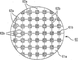
图18是示意说明现有的废气过滤器垂直于长度方向的截面的截面图。Fig. 18 is a cross-sectional view schematically illustrating a cross-section perpendicular to the longitudinal direction of a conventional exhaust gas filter.
该废气过滤器60具有下述截面形状,即在棋盘状格子的交点上有比构成该棋盘格子的正四边形小的四边形。该废气过滤器60包括对应小四边形的小容积贯通孔61b和存在于小容积贯通孔61b周围的大容积贯通孔61a,并且在这些贯通孔之间形成有间隔壁62a、62b(参照专利文献1、2)。The
图19(a)~(d)是示意说明以往的其它废气过滤器垂直于长度方向的截面的截面图。19( a ) to ( d ) are cross-sectional views schematically illustrating a cross-section perpendicular to the longitudinal direction of another conventional exhaust gas filter.
该废气过滤器300~330具有各种形状的大容积贯通孔301a、311a、321a、331a和小容积贯通孔301b、311b、321b、331b,并且在这些贯通孔之间形成有间隔壁302、312、322、332。The
间隔壁302、312、322、332都是分隔大容积贯通孔301a、311a、321a、331a和小容积贯通孔301b、311b、321b、331b的间隔壁,并且可以没有分隔大容积贯通孔301a、311a、321a、331a之间的间隔壁(参照专利文献3~7)。
此外,作为其它的现有技术,公开了大容积贯通孔的孔间距约为1.0mm~2.5mm的过滤器(参照专利文献8)。In addition, as another prior art, a filter having large-volume through-holes with a pitch of approximately 1.0 mm to 2.5 mm is disclosed (see Patent Document 8).
此外,还公开了一种过滤器(参照专利文献9),其中,大容积贯通孔的容积率为60%~70%,小容积贯通孔的容积率为20%~30%,且大容积贯通孔的孔间距约为2.5mm~5.0mm。In addition, a filter is also disclosed (see Patent Document 9), in which the volume ratio of the large-volume through-hole is 60% to 70%, the volume ratio of the small-volume through-hole is 20% to 30%, and the large-volume through-hole The hole spacing of the holes is about 2.5 mm to 5.0 mm.
图20是这些过滤器200垂直于长度方向的截面(下文,简称截面)的截面示意图,该过滤器200中,在截面的形状为6边形的大容积贯通孔201的周围配置了截面的形状为3角形的小容积贯通孔202。20 is a schematic cross-sectional view of a cross-section (hereinafter referred to as a cross-section) perpendicular to the longitudinal direction of these
此外,还公开了一种过滤器(参照专利文献10、11),其中,小容积贯通孔的截面的总面积与大容积贯通孔的截面的总面积相比的百分率为40%~120%。In addition, a filter is disclosed (see
图21是说明这种过滤器垂直于其长度方向的截面的截面示意图,在该过滤器210中,在上述截面的形状为正6边形的大容积贯通孔211的周围配置了上述截面形状为扁6边形的小容积贯通孔212。此外,在外周附近,并存正6边形大容积贯通孔211和梯形大容积贯通孔213。此外,还公开了一种过滤器(例如,参照专利文献10的图3),其中,通过使流入侧贯通孔的数目比流出侧贯通孔的数目多,从而使废气流入侧的开口率比废气流出侧的开口率大。FIG. 21 is a schematic cross-sectional view illustrating a cross-section of this filter perpendicular to its length direction. In this
此外,关于过滤器,公开了调整壁的厚度、物性值的技术(参照专利文献12、13),并且还公开了贯通孔的截面包括正方形和长方形的过滤器。(例如,参照专利文献14)。In addition, regarding filters, techniques for adjusting wall thickness and physical property values are disclosed (see Patent Documents 12 and 13), and filters having through-holes with square or rectangular cross-sections are also disclosed. (For example, refer to Patent Document 14).
此外,还公开了具有2种形状贯通孔的过滤器,特别是具有八边形和四边形贯通孔的过滤器(参照专利文献15、16),还公开了具有相对大的正方形和相对小的正方形这2种类型贯通孔的过滤器(专利文献17)。In addition, filters with two types of through-holes are disclosed, especially filters with octagonal and quadrilateral through-holes (refer to Patent Documents 15 and 16), and relatively large square and relatively small square A filter of these two types of through holes (Patent Document 17).
进一步,还公开了废气流出侧的开口率是废气流出侧的开口率的1.1倍~15倍的蜂窝过滤器(参照专利文献18)。Furthermore, a honeycomb filter is disclosed in which the aperture ratio on the exhaust gas outflow side is 1.1 to 15 times that of the exhaust gas outflow side (see Patent Document 18).
对于上文所述的全部现有技术公开的过滤器,与废气流入侧的开口率和废气流出侧的开口率相等的过滤器相比,由于废气流入侧的开口率相对大,将其用作废气净化用过滤器时,增大了对颗粒捕集的极限量,从而可以延长到再生前的可使用时间。With regard to all the filters disclosed in the prior art described above, since the opening ratio of the exhaust gas inflow side is relatively large compared with the filter whose opening ratio on the exhaust gas inflow side is equal to that on the exhaust gas outflow side, it is used as When the filter is used for exhaust gas purification, the limit of particle collection is increased, so that the usable time before regeneration can be extended.
专利文献1:美国专利第4417908号说明书Patent Document 1: Specification of US Patent No. 4417908
专利文献2:特开昭58-196820号公报Patent Document 2: JP-A-58-196820 Gazette
专利文献3:美国专利第4364761号公报Patent Document 3: US Patent No. 4364761
专利文献4:特开昭56-124417号公报Patent Document 4: JP-A-56-124417
专利文献5:特开昭62-96717号公报Patent Document 5: JP-A-62-96717
专利文献6:美国专利第4276071号公报Patent Document 6: US Patent No. 4276071
专利文献7:特开昭56-124418号公报Patent Document 7: JP-A-56-124418
专利文献8:实愿昭56-187890号缩微胶卷(实开昭58-92409号(参照第4页、图6))Patent Document 8: Microfilm No. 56-187890 of Shiyuanzhao (Shikaizhao No. 58-92409 (see page 4, Fig. 6))
专利文献9:特开平5-68828号公报(日本专利第3130587号说明书(第1页))Patent Document 9: JP-A-5-68828 (Japanese Patent No. 3130587 specification (page 1))
专利文献10:特开2001-334114号公报(参照第5页、图2)Patent Document 10: Japanese Unexamined Patent Publication No. 2001-334114 (see page 5, FIG. 2 )
专利文献11:国际公开第WO02/100514号小册子Patent Document 11: International Publication No. WO02/100514 Pamphlet
专利文献12:美国专利第4416676号说明书Patent Document 12: Specification of US Patent No. 4416676
专利文献13:美国专利第4420316号说明书Patent Document 13: Specification of US Patent No. 4420316
专利文献14:特开昭58-150015号公报Patent Document 14: JP-A-58-150015
专利文献15:法国专利发明第2789327号说明书Patent Document 15: French Patent Invention No. 2789327 Specification
专利文献16:国际公开第WO02/10562号小册子Patent Document 16: International Publication No. WO02/10562 Pamphlet
专利文献17:国际公开第WO03/20407号小册子Patent Document 17: International Publication No. WO03/20407 Pamphlet
专利文献18:国际公开第WO03/80218号小册子Patent Document 18: International Publication No. WO03/80218 Pamphlet
发明内容 Contents of the invention
但是,将这些过滤器与通常的过滤器(即废气流入侧的开口率和流出侧的开口率相等的过滤器)相比可知,其初期的压力损失相当高。However, when these filters are compared with ordinary filters (that is, filters in which the opening ratio on the exhaust gas inflow side is equal to the opening ratio on the outflow side), it can be seen that the initial pressure loss is considerably high.
此外,还已知:伴随着废气流入侧的开口率的增大,过滤器的强度降低,所以由于使用时的发动机的振动、再生时颗粒的燃烧所产生的热冲击的作用,易在过滤器中产生裂纹。In addition, it is also known that as the opening ratio of the exhaust gas inflow side increases, the strength of the filter decreases, so the vibration of the engine during use and the thermal shock caused by the combustion of particles during regeneration are easy to damage the filter. cracks in.
另一方面,通过在不改变入口侧的开口率的情况下将过滤器的体积增大,则增大废气流入侧的贯通孔的比表面积(滤过面积)和总容积时可以降低压力损失。On the other hand, by increasing the volume of the filter without changing the opening ratio on the inlet side, the pressure loss can be reduced by increasing the specific surface area (filtration area) and total volume of the through holes on the exhaust gas inflow side.
但是,由于增大过滤器的体积时,难以在内燃机的周边确保配置过滤器的空间;伴随着体积增大,热应答性变差,难以使烟炱燃烧,热冲击导致易产生裂纹,所以只增大过滤器的体积不能成为解决上述问题的有效的方法。However, when the volume of the filter is increased, it is difficult to secure a space for arranging the filter around the internal combustion engine; as the volume increases, the thermal responsiveness deteriorates, it is difficult to burn soot, and cracks are likely to occur due to thermal shock, so only Increasing the volume of the filter cannot be an effective solution to the above-mentioned problems.
本发明的发明人为了解决上述问题进行了精心研究,结果发现,蜂窝结构体的体积和该蜂窝结构体在入口侧的开口率具有规定的关系时,该蜂窝结构体虽然仍保持尺寸紧凑,但是可以具有较长的寿命,进一步,由于其热应答性优异,所以能够得到裂纹极限高、可靠性优异的蜂窝结构体,从而实现了本发明。The inventors of the present invention conducted intensive studies to solve the above problems, and as a result found that when the volume of the honeycomb structure has a predetermined relationship with the opening ratio of the honeycomb structure on the inlet side, the honeycomb structure remains compact in size, but It can have a long life, and furthermore, since it is excellent in thermal responsiveness, a honeycomb structure with a high crack limit and excellent reliability can be obtained, thereby achieving the present invention.
而且,对于本发明的蜂窝结构体,若上述蜂窝结构体的体积和上述开口率以及内燃机的排气量具有规定的关系,则在蜂窝结构体上不易产生裂纹,可以有效地利用蜂窝结构体的性能。Moreover, in the honeycomb structure of the present invention, if the volume of the honeycomb structure has a predetermined relationship with the above-mentioned opening ratio and the exhaust gas volume of the internal combustion engine, cracks are less likely to occur on the honeycomb structure, and the capacity of the honeycomb structure can be effectively utilized. performance.
即,本发明的蜂窝结构体是具有蜂窝结构的柱状蜂窝结构体,大量贯通孔隔着壁部沿长度方向平行设置,且上述贯通孔在任意一侧的端部被封口,其特征在于,上述蜂窝结构体的体积Y(L)和入口侧的开口率X(%)具有下述式(1)的关系;That is, the honeycomb structure of the present invention is a columnar honeycomb structure having a honeycomb structure, a large number of through-holes are arranged in parallel in the longitudinal direction through the wall, and the ends of the above-mentioned through-holes are sealed, and it is characterized in that the above-mentioned The volume Y(L) of the honeycomb structure and the opening ratio X(%) on the inlet side have the relationship of the following formula (1);
Y≤-1.1X+68.5并且Y≤19、35≤X≤56 (1)。Y≤-1.1X+68.5 and Y≤19, 35≤X≤56 (1).
对于本发明的蜂窝结构体,优选蜂窝结构体的体积Y(L)和上述入口侧的开口率X(%)具有下述式(2)的关系;For the honeycomb structure of the present invention, it is preferable that the volume Y (L) of the honeycomb structure and the opening ratio X (%) on the inlet side have the relationship of the following formula (2);
Y≤-1.1X+66.3并且2.5≤Y≤19、35≤X≤56 (2)。Y≤-1.1X+66.3 and 2.5≤Y≤19, 35≤X≤56 (2).
此外,将上述蜂窝结构体用作内燃机的废气净化用蜂窝结构体时,优选上述蜂窝结构体的体积Y(L)、上述入口侧的开口率X(%)和上述内燃机的排气量V(L)具有下述式(3)的关系;In addition, when the above-mentioned honeycomb structure is used as a honeycomb structure for exhaust gas purification of an internal combustion engine, it is preferable that the volume Y (L) of the above-mentioned honeycomb structure, the opening ratio X (%) of the above-mentioned inlet side, and the exhaust gas volume V (%) of the above-mentioned internal combustion engine L) has the relation of following formula (3);
100V-400≤X·Y≤100V+100 (3)。100V-400≤X Y≤100V+100 (3).
对于上述蜂窝结构体,上述大量贯通孔优选包括在废气的流入侧开口的大容积贯通孔和在废气的流出侧开口的小容积贯通孔,所述大容积贯通孔的垂直于长度方向的截面的面积相对大,所述小容积贯通孔的上述截面的面积相对小;并且优选上述大容积贯通孔和上述小容积贯通孔的数目实质上相等。In the above-mentioned honeycomb structure, the above-mentioned large number of through-holes preferably include large-volume through-holes opened on the exhaust gas inflow side and small-volume through-holes opened on the exhaust gas outflow side, the cross-section of the large-volume through-holes perpendicular to the longitudinal direction The area is relatively large, and the cross-sectional area of the small-volume through-hole is relatively small; and preferably, the numbers of the large-volume through-hole and the small-volume through-hole are substantially equal.
对于上述蜂窝结构体,优选通过密封材料层将柱状的多孔质部件多个结合在一起来构成上述蜂窝结构体;所述多孔质部件中,隔着间隔壁沿长度方向上平行设置有大量贯通孔。For the above-mentioned honeycomb structure, it is preferable to form the above-mentioned honeycomb structure by combining a plurality of columnar porous members through a sealing material layer; in the said porous member, a large number of through-holes are arranged in parallel in the longitudinal direction through partition walls. .
对于上述蜂窝结构体,大量贯通孔垂直其长度方向的截面的形状优选包括至少2种形状。In the above-mentioned honeycomb structure, it is preferable that the cross-sectional shapes of the plurality of through-holes perpendicular to the longitudinal direction include at least two shapes.
此外,上述大容积贯通孔和/或上述小容积贯通孔垂直于长度方向的截面的形状优选为多边形,例如优选八边形和四边形。In addition, the shape of the cross-section perpendicular to the longitudinal direction of the above-mentioned large-volume through-hole and/or the above-mentioned small-volume through-hole is preferably polygonal, such as preferably octagonal and quadrangular.
对于上述蜂窝结构体,上述大容积贯通孔的截面面积与上述小容积贯通孔的截面面积的比优选为1.55~2.75。In the honeycomb structure, the ratio of the cross-sectional area of the large-volume through-holes to the cross-sectional area of the small-volume through-holes is preferably 1.55 to 2.75.
此外,对于上述大容积贯通孔和/或上述小容积贯通孔垂直于其长度方向的截面,优选由曲线构成其角部的附近。In addition, it is preferable that the vicinity of the corners of the above-mentioned large-volume through-hole and/or the above-mentioned small-volume through-hole in cross-section perpendicular to the longitudinal direction be constituted by a curved line.
对于上述蜂窝结构体,优选相邻的上述大容积贯通孔在垂直于长度方向的截面的重心间距离和相邻的上述小容积贯通孔在垂直于长度方向的截面的重心间距离相等。In the above-mentioned honeycomb structure, the distance between the centroids of the cross-sections perpendicular to the longitudinal direction of the adjacent large-volume through-holes is preferably equal to the distance between the centroids of the cross-sections perpendicular to the longitudinal direction of the adjacent small-volume through-holes.
对于上述蜂窝结构体,优选在隔开大量贯通孔的间隔壁的表面和/或间隔壁的内部上负载有催化剂。In the above-mentioned honeycomb structure, it is preferable that a catalyst is supported on the surface of the partition walls separating a large number of through-holes and/or inside the partition walls.
此外,优选在大量贯通孔的内部平行于长度方向设置有凸部和/或凹部,上述凸部和/或凹部优选设置在入口侧贯通孔共有的间隔壁上。In addition, it is preferable that protrusions and/or recesses are provided parallel to the longitudinal direction inside a large number of through holes, and the protrusions and/or recesses are preferably provided on partition walls shared by the inlet side through holes.
此外,优选上述凸部和/或凹部能够发挥作为选择性负载催化剂部位、颗粒捕集部位以及蜂窝结构体的耐热应力改善部位中的至少1个的作用。In addition, it is preferable that the above-mentioned convex portion and/or concave portion can function as at least one of a selective catalyst supporting portion, a particle trapping portion, and a thermal stress-improving portion of the honeycomb structure.
对于上述蜂窝结构体,优选等压强度大于等于7MPa,优选A轴的压缩强度大于等于18MPa。For the above-mentioned honeycomb structure, the isostatic strength is preferably equal to or greater than 7 MPa, and the compressive strength of the A axis is preferably equal to or greater than 18 MPa.
对于上述蜂窝结构体,大量贯通孔垂直于长度方向的截面的形状优选是1种形状,并且,包括至少2种截面面积。In the above-mentioned honeycomb structure, it is preferable that the cross-sectional shape of the plurality of through-holes perpendicular to the longitudinal direction is one shape, and at least two kinds of cross-sectional areas are included.
对于上述蜂窝结构体,优选主成分是选自SiC、Si3N4、钛酸铝、堇青石、莫来石、氧化铝、尖晶石、锂铝硅酸盐、Fe-Cr-Al类金属以及金属硅的至少1种。For the above-mentioned honeycomb structure, it is preferable that the main component is selected from SiC, Si 3 N 4 , aluminum titanate, cordierite, mullite, alumina, spinel, lithium aluminum silicate, Fe-Cr-Al metalloid and at least one metal silicon.
此外,上述蜂窝结构体优选用于车辆的废气净化装置。In addition, the above-mentioned honeycomb structure is preferably used in an exhaust gas purification device for a vehicle.
发明的效果The effect of the invention
根据本发明的蜂窝结构体,由于上述蜂窝结构体的体积Y和上述入口侧的开口率X具有上述式(1)的关系,所以能够在保持该蜂窝结构体的尺寸紧凑的情况下具有较长的寿命,进一步,由于机械强度和热应答性优异,所以裂纹极限高,可靠性优异。According to the honeycomb structure of the present invention, since the volume Y of the honeycomb structure and the opening ratio X on the inlet side have the relationship of the above formula (1), it is possible to maintain a compact size of the honeycomb structure with a long Furthermore, due to its excellent mechanical strength and thermal responsiveness, it has a high crack limit and excellent reliability.
附图说明 Description of drawings
图1是说明本发明的蜂窝结构体的一个例子的立体示意图。Fig. 1 is a schematic perspective view illustrating an example of a honeycomb structure of the present invention.
图2(a)是说明构成图1所示的蜂窝结构体的多孔质部件的一个例子的立体示意图;图2(b)是图2(a)所示的多孔质部件沿A-A线的截面图。Fig. 2 (a) is a schematic perspective view illustrating an example of a porous member constituting the honeycomb structure shown in Fig. 1; Fig. 2 (b) is a cross-sectional view of the porous member shown in Fig. 2 (a) along line A-A .
图3(a)是说明本发明的蜂窝结构体的另外一个例子的立体示意图;图3(b)是图3(a)所示的蜂窝结构体沿B-B线的截面图。Fig. 3(a) is a schematic perspective view illustrating another example of the honeycomb structure of the present invention; Fig. 3(b) is a cross-sectional view of the honeycomb structure shown in Fig. 3(a) along line B-B.
图4(a)~图4(d)是说明构成本发明的另外一个例子的蜂窝结构体的多孔质部件垂直于长度方向的截面的截面示意图。4(a) to 4(d) are schematic cross-sectional views illustrating a cross-section perpendicular to the longitudinal direction of a porous member constituting a honeycomb structure according to another example of the present invention.
图5(a)~图5(f)是说明构成本发明的另外一个例子的蜂窝结构体的多孔质部件垂直于长度方向的截面的纵截面示意图。5( a ) to 5 ( f ) are schematic longitudinal cross-sectional views illustrating a cross-section perpendicular to the longitudinal direction of a porous member constituting a honeycomb structure according to another example of the present invention.
图6(a)~图6(d)是说明构成本发明的另外一个例子的蜂窝结构体的多孔质部件垂直于长度方向的截面的纵截面示意图。图6(e)是说明构成比较例涉及的蜂窝结构体的多孔质部件垂直于长度方向的截面的纵截面示意图。6( a ) to 6 ( d ) are schematic longitudinal cross-sectional views illustrating a cross-section perpendicular to the longitudinal direction of a porous member constituting a honeycomb structure according to another example of the present invention. Fig. 6(e) is a schematic longitudinal cross-sectional view illustrating a cross-section perpendicular to the longitudinal direction of a porous member constituting a honeycomb structure according to a comparative example.
图7是说明使用本发明的废气净化用蜂窝结构体的废气净化装置的一个例子的截面示意图。7 is a schematic cross-sectional view illustrating an example of an exhaust gas purification device using the honeycomb structure for exhaust gas purification of the present invention.
图8是说明由本发明的蜂窝结构体形成的过滤器的过滤器体积和入口侧的开口率的关系的图。Fig. 8 is a graph illustrating the relationship between the filter volume of a filter formed of the honeycomb structure of the present invention and the opening ratio on the inlet side.
图9是说明由本发明的蜂窝结构体形成的过滤器的过滤器体积、入口侧的开口率和排气量的关系的图。Fig. 9 is a graph illustrating the relationship between the filter volume, the opening ratio on the inlet side, and the exhaust gas volume of a filter formed of the honeycomb structure of the present invention.
图10是说明由具有图4(a)~图4(d)所示的截面形状的蜂窝结构体形成的过滤器的入口侧的开口率和再生极限值之间的关系的图。Fig. 10 is a diagram illustrating the relationship between the opening ratio on the inlet side of a filter formed of a honeycomb structure having the cross-sectional shape shown in Figs. 4(a) to 4(d) and a regeneration limit value.
图11是说明由具有图5(a)、图5(b)所示的截面形状的蜂窝结构体形成的过滤器的入口侧的开口率和再生极限值之间的关系的图。Fig. 11 is a graph illustrating the relationship between the opening ratio and the regeneration limit value on the inlet side of a filter formed of a honeycomb structure having the cross-sectional shape shown in Fig. 5(a) and Fig. 5(b).
图12是说明由具有图5(e)、图5(f)所示的截面形状的蜂窝结构体形成的过滤器的入口侧的开口率和再生极限值之间的关系的图。Fig. 12 is a diagram illustrating the relationship between the opening ratio and regeneration limit value on the inlet side of a filter formed of a honeycomb structure having the cross-sectional shape shown in Fig. 5(e) and Fig. 5(f).
图13是说明由具有图6(a)~图6(d)所示的截面形状的蜂窝结构体形成的过滤器的入口侧的开口率和再生极限值之间的关系的图。Fig. 13 is a diagram illustrating the relationship between the aperture ratio on the inlet side of a filter formed of a honeycomb structure having the cross-sectional shape shown in Figs. 6(a) to 6(d) and a regeneration limit value.
图14是说明由具有图4(a)~图4(d)所示的截面形状的蜂窝结构体形成的过滤器的入口侧的开口率和热应答性之间的关系的图。Fig. 14 is a diagram illustrating the relationship between the opening ratio and thermal responsiveness at the inlet side of a filter formed of a honeycomb structure having the cross-sectional shape shown in Figs. 4(a) to 4(d).
图15是说明由具有图5(a)、图5(b)所示的截面形状的蜂窝结构体形成的过滤器的入口侧的开口率和热应答性之间的关系的图。Fig. 15 is a diagram illustrating the relationship between the opening ratio and thermal responsiveness at the inlet side of a filter formed of a honeycomb structure having the cross-sectional shape shown in Fig. 5(a) and Fig. 5(b).
图16是说明由具有图5(e)、图5(f)所示的截面形状的蜂窝结构体形成的过滤器的入口侧的开口率和热应答性之间的关系的图。Fig. 16 is a diagram illustrating the relationship between the opening ratio and the thermal responsiveness of the inlet side of a filter formed of a honeycomb structure having the cross-sectional shape shown in Fig. 5(e) and Fig. 5(f).
图17是说明由具有图6(a)~图6(d)所示的截面形状的蜂窝结构体形成的过滤器的入口侧的开口率和热应答性之间的关系的图。Fig. 17 is a diagram illustrating the relationship between the opening ratio and thermal responsiveness at the inlet side of a filter formed of a honeycomb structure having the cross-sectional shape shown in Figs. 6(a) to 6(d).
图18是说明由以往的蜂窝结构体形成的过滤器的另外一个例子的纵截面示意图。Fig. 18 is a schematic longitudinal sectional view illustrating another example of a filter formed of a conventional honeycomb structure.
图19(a)~图19(d)是说明由以往的废气净化用蜂窝结构体形成的过滤器的其它例子的纵截面示意图。19( a ) to 19( d ) are schematic longitudinal cross-sectional views illustrating other examples of filters formed of conventional exhaust gas-purifying honeycomb structures.
图20是说明以往的多孔质陶瓷部件的垂直于长度方向的截面的截面示意图,其中,大容积贯通孔和小容积贯通孔的数目实质上是1∶2。20 is a schematic cross-sectional view illustrating a cross-section perpendicular to the longitudinal direction of a conventional porous ceramic member in which the number of large-volume through-holes and small-volume through-holes is substantially 1:2.
图21是说明由以往的蜂窝结构体形成的过滤器垂直于长度方向的截面的截面示意图。Fig. 21 is a schematic cross-sectional view illustrating a cross-section perpendicular to the longitudinal direction of a filter formed of a conventional honeycomb structure.
符号说明Symbol Description
10、30蜂窝结构体10, 30 honeycomb structure
13、14密封材料层13, 14 sealing material layer
15多孔质构件15 porous components
20、30、40、50、70、110、120、130、140多孔质部件20, 30, 40, 50, 70, 110, 120, 130, 140 porous parts
160、170、180、260、270、280多孔质部件160, 170, 180, 260, 270, 280 porous parts
21a、31a、41a、51a、71a大容积贯通孔21a, 31a, 41a, 51a, 71a large volume through holes
114、124、134凸部114, 124, 134 convex part
161a、171a、181a、261a、271a、281a大容积贯通孔161a, 171a, 181a, 261a, 271a, 281a large volume through holes
21b、31b、41b、51b、71b小容积贯通孔21b, 31b, 41b, 51b, 71b small volume through holes
161b、171b、181b、261b、271b、281b小容积贯通孔161b, 171b, 181b, 261b, 271b, 281b small volume through holes
22封口材料22 sealing material
23、43、53、73间隔壁23, 43, 53, 73 partition walls
163、173、183、263、273、283间隔壁163, 173, 183, 263, 273, 283 partition walls
33壁部33 wall
具体实施方式 Detailed ways
本发明的蜂窝结构体是具有蜂窝结构的柱状蜂窝结构体,大量贯通孔隔着壁部沿长度方向平行设置,且上述贯通孔在任意一侧的端部被封口,其特征在于,上述蜂窝结构体的体积Y(L)和入口侧的开口率X(%)具有下述式(1)的关系;The honeycomb structure of the present invention is a columnar honeycomb structure with a honeycomb structure, a large number of through-holes are arranged in parallel along the longitudinal direction through the wall, and the ends of the above-mentioned through-holes are sealed, and it is characterized in that the above-mentioned honeycomb structure The volume Y (L) of the body and the opening ratio X (%) of the inlet side have the relationship of the following formula (1);
Y≤-1.1X+68.5并且Y≤19、35≤X≤56 (1)。Y≤-1.1X+68.5 and Y≤19, 35≤X≤56 (1).
其中,上述入口侧的开口率(%)是,相对于蜂窝结构体的入口侧的端面全体的面积,入口侧贯通孔组的面积的总和所占的百分率。Here, the opening ratio (%) on the inlet side is the percentage of the total area of the inlet-side through-hole group to the entire area of the inlet-side end surface of the honeycomb structure.
本发明的蜂窝结构体是具有蜂窝结构的柱状蜂窝结构体,大量贯通孔隔着壁部沿长度方向平行设置,且上述贯通孔在任意一侧的端部被封口。The honeycomb structure of the present invention is a columnar honeycomb structure having a honeycomb structure, a large number of through-holes are arranged in parallel in the longitudinal direction via wall portions, and the ends of the through-holes are sealed on either side.
对于上述蜂窝结构体,可以通过密封材料层将柱状的多孔质部件多个结合在一起来构成,所述多孔质部件中,大量贯通孔隔着间隔壁沿长度方向平行设置(下文,将上述蜂窝结构体称为集合体型蜂窝结构体);也可以由整体作为一体烧结而成的多孔质体构成(下文将上述蜂窝结构体称为一体型蜂窝结构体)。此外,上述蜂窝结构体也可以是按使贯通孔重合的方式在长度方向上层积层积部件而形成的。The above-mentioned honeycomb structure can be constructed by combining a plurality of columnar porous members through a sealing material layer, and in the porous member, a large number of through-holes are arranged in parallel in the longitudinal direction through partition walls (hereinafter, the above-mentioned honeycomb structure). The structure is called an aggregate type honeycomb structure); it may also be composed of a porous body sintered as a whole (hereinafter, the above-mentioned honeycomb structure is called an integrated type honeycomb structure). In addition, the above-mentioned honeycomb structure may be formed by laminating laminated members in the longitudinal direction so that the through-holes overlap.
图1是说明作为本发明的蜂窝结构体的一个例子的集合体型的蜂窝结构体的具体例子的立体示意图,图2(a)是说明构成图1所示的蜂窝结构体的多孔质部件的一个例子的立体示意图,图2(b)是图2(a)所示的多孔质部件沿A-A线的截面图。Fig. 1 is a schematic perspective view illustrating a specific example of an aggregate-type honeycomb structure as an example of the honeycomb structure of the present invention, and Fig. 2(a) is a diagram illustrating one of porous members constituting the honeycomb structure shown in Fig. 1 As a schematic perspective view of an example, Fig. 2(b) is a cross-sectional view of the porous member shown in Fig. 2(a) along line A-A.
如图1所示,对于本发明的蜂窝结构体10,多个多孔质部件20隔着密封材料层14结合在一起而构成了多孔质构件15,在该多孔质构件15的周围形成了用于防止废气泄漏的密封材料层13。As shown in FIG. 1, in the
此外,对于该多孔质部件20,沿其长度方向平行设置有大量贯通孔21,该贯通孔21包括2种贯通孔,其一是大容积贯通孔21a,该大容积贯通孔21a的垂直于长度方向的截面面积相对大,其二是小容积贯通孔21b,该小容积贯通孔21b的上述截面的面积相对小;并且大容积贯通孔21a在蜂窝结构体10的废气出口侧的端部由封口材料22封口,另一方面,小容积贯通孔21b在蜂窝结构体10的废气入口侧的端部由封口材料22封口,隔开这些贯通孔的间隔壁23发挥作为蜂窝结构体的作用。即,流入大容积贯通孔21a的废气必定通过这些间隔壁23后,才能从小容积贯通孔21b流出。In addition, for this
对于这种蜂窝结构体10,其体积Y(L)和大容积贯通孔21a的入口侧的开口率X(%)具有下述式(1)的关系;For such a
Y≤-1.1X+68.5并且Y≤19、35≤X≤56 (1)。Y≤-1.1X+68.5 and Y≤19, 35≤X≤56 (1).
一般,将蜂窝结构体配置于废气的流路中来使用时,灰烬从蜂窝结构体的后部(出口侧)开始蓄积。因此,为了保证长时间蓄积灰烬后压力损失也不会增大,即,为了使蜂窝体的寿命延长,有必要增大在入口侧开口的贯通孔的容积。于是,为了增大在入口侧开口的贯通孔的容积,有必要提高入口侧的开口率,此外,还有必要增大蜂窝结构体的容积。In general, when a honeycomb structure is placed in an exhaust gas flow path and used, ash accumulates from the rear (outlet side) of the honeycomb structure. Therefore, in order to ensure that the pressure loss does not increase even after ash is accumulated for a long period of time, that is, in order to prolong the life of the honeycomb body, it is necessary to increase the volume of the through-holes opened on the inlet side. Therefore, in order to increase the volume of the through-holes opened on the inlet side, it is necessary to increase the aperture ratio on the inlet side, and also to increase the volume of the honeycomb structure.
但是,若开口率增大,则由于蜂窝结构体整体的密度下降,降低了再生极限值(将蓄积的颗粒燃烧时不会产生裂纹的颗粒最大蓄积量),也缩短了再生前的可使用时间。However, if the aperture ratio is increased, the density of the entire honeycomb structure decreases, reducing the regeneration limit value (the maximum accumulation of particles that will not cause cracks when the accumulated particles are burned), and the usable time before regeneration is also shortened. .
此外,若蜂窝结构体的容积增大,则蜂窝结构体整体的热容量增大,蜂窝结构体整体的升温性变差。In addition, when the volume of the honeycomb structure increases, the heat capacity of the entire honeycomb structure increases, and the temperature rise property of the entire honeycomb structure deteriorates.
与此相对,在具有上述式(1)的关系的本发明的蜂窝结构体中,首先,限定了蜂窝结构体的容积小于等于19L(升)。如此,通过设定蜂窝结构体的体积的上限,可以防止蜂窝结构体整体的升温性变差。On the other hand, in the honeycomb structure of the present invention having the relationship of the above formula (1), first, the volume of the honeycomb structure is limited to 19 L (liter). In this way, by setting the upper limit of the volume of the honeycomb structure, it is possible to prevent the temperature rise property of the entire honeycomb structure from deteriorating.
此外,将入口侧的开口率的上限和下限设定为35%~65%。若入口侧的开口率小于35%,则由于构成蜂窝结构体的多孔质体的重量过大,热容量增大,升温性变差。此外,由于增大了壁部的量(容积),压力损失也容易增大。另一方面,若入口侧的开口率超过65%,如上所述,蜂窝结构体整体的密度降低,并且再生极限值降低。In addition, the upper and lower limits of the aperture ratio on the inlet side are set to 35% to 65%. If the opening ratio on the inlet side is less than 35%, since the weight of the porous body constituting the honeycomb structure is too large, the heat capacity increases and the temperature rise property deteriorates. In addition, since the amount (volume) of the wall portion is increased, the pressure loss also tends to increase. On the other hand, if the opening ratio on the inlet side exceeds 65%, the density of the entire honeycomb structure decreases as described above, and the regeneration limit value decreases.
在上述的开口率和蜂窝结构体容积的范围内,进一步,设定上述入口侧的开口率和蜂窝结构体的容积的范围,使其具有下述式(1)所示的关系。Within the range of the aperture ratio and the volume of the honeycomb structure, the range of the aperture ratio on the inlet side and the volume of the honeycomb structure is further set so as to have the relationship represented by the following formula (1).
Y≤-1.1X+68.5 (1)Y≤-1.1X+68.5 (1)
这是因为,即使在上述的开口率和蜂窝结构体容积的范围内,如果不满足上述式(1),再生极限值仍然降低,再生前的可使用时间缩短,强度降低,设置于废气配管等时所要求的机械特性变差。This is because even within the range of the above-mentioned opening ratio and volume of the honeycomb structure, if the above-mentioned formula (1) is not satisfied, the regeneration limit value will still decrease, the usable time before regeneration will be shortened, and the strength will decrease. The required mechanical properties deteriorate.
对于本发明的蜂窝结构体,由于按满足上述式(1)来设定入口侧的开口率和蜂窝结构体的容积的关系,所以可以增大在入口侧开口的贯通孔的容积,并且抑制压力损失的上升,能够蓄积大量的颗粒、灰烬,同时,抑制了蜂窝结构体整体的密度降低,防止了再生极限值的降低,并且热应答性优异,从而延长了寿命。In the honeycomb structure of the present invention, since the relationship between the opening ratio on the inlet side and the volume of the honeycomb structure is set so as to satisfy the above formula (1), the volume of the through-holes opening on the inlet side can be increased and the pressure can be suppressed. The increase in loss can accumulate a large amount of particles and ash, and at the same time, the decrease in the density of the honeycomb structure as a whole is suppressed, the regeneration limit value is prevented, and the thermal response is excellent, thereby prolonging the life.
对于本发明的蜂窝结构体,上述蜂窝结构体的体积Y(L)和上述入口侧的开口率X(%)优选具有下述式(2)的关系;In the honeycomb structure of the present invention, the volume Y (L) of the honeycomb structure and the opening ratio X (%) on the inlet side preferably have the relationship of the following formula (2):
Y≤-1.1X+66.3并且2.5≤Y≤19、35≤X≤56 (2)。Y≤-1.1X+66.3 and 2.5≤Y≤19, 35≤X≤56 (2).
在具有上述式(2)的关系的蜂窝结构体中,设定蜂窝结构体的体积大于等于2.5L。若蜂窝结构体的体积小于2.5L,则蜂窝结构体的体积变小。此时,若增大入口侧的开口率等以增大颗粒的蓄积总量时,则易产生裂纹。In the honeycomb structure having the relationship of the above formula (2), the volume of the honeycomb structure is set to be 2.5 L or more. When the volume of the honeycomb structure is less than 2.5 L, the volume of the honeycomb structure becomes small. At this time, if the opening ratio on the inlet side is increased to increase the total amount of accumulated particles, cracks are likely to occur.
此外,即使在上述的开口率和蜂窝结构体容积的范围,若不满足式(2),则再生极限值也不是充分的。In addition, even within the above-mentioned ranges of the aperture ratio and the volume of the honeycomb structure, if the expression (2) is not satisfied, the regeneration limit value is not sufficient.
对于本发明的蜂窝结构体,通过设定入口侧的开口率和蜂窝结构体的容积的关系使其满足上述式(2),可以抑制压力损失的上升,也可以蓄积更多的颗粒、灰烬,同时,能够抑制蜂窝结构体整体密度的降低,也能更有效地防止再生极限值的降低,并且热应答性优异,从而延长了寿命。For the honeycomb structure of the present invention, by setting the relationship between the opening ratio on the inlet side and the volume of the honeycomb structure so as to satisfy the above formula (2), the increase in pressure loss can be suppressed, and more particles and ash can be accumulated. At the same time, the decrease in the overall density of the honeycomb structure can be suppressed, the decrease in the regeneration limit value can be prevented more effectively, and the thermal responsiveness is excellent, thereby prolonging the life.
此外,将本发明的蜂窝结构体用作内燃机的废气净化用蜂窝结构体时,优选上述蜂窝结构体的体积Y(L)、上述入口侧的开口率X(%)和上述内燃机的排气量V(L)具有下述式(3)的关系;In addition, when the honeycomb structure of the present invention is used as a honeycomb structure for purifying exhaust gas of an internal combustion engine, it is preferable that the volume Y (L) of the honeycomb structure, the opening ratio X (%) on the inlet side, and the exhaust gas volume of the internal combustion engine V(L) has the relationship of the following formula (3);
100V-400≤X·Y≤100V+100 (3)。100V-400≤X·Y≤100V+100 (3).
将上述蜂窝结构体用作内燃机的废气净化用过滤器时,由于伴随着内燃机排气量的增加,气体的流量增加,所以,蜂窝结构体的阻力增加。When the above-mentioned honeycomb structure is used as a filter for purifying exhaust gas of an internal combustion engine, the resistance of the honeycomb structure increases because the gas flow rate increases with an increase in the exhaust gas volume of the internal combustion engine.
此时,虽然可以增大蜂窝结构体的体积来减小压力损失(排压),但是如上所述,增大蜂窝结构体的体积时,蜂窝结构体整体的热容量增大,热应答性降低。进一步,在蜂窝结构体上负载催化剂时,随着流入蜂窝结构体的废气的流量的增加,催化剂对废气的反应性变差。At this time, although the volume of the honeycomb structure can be increased to reduce the pressure loss (exhaust pressure), as described above, when the volume of the honeycomb structure is increased, the heat capacity of the entire honeycomb structure increases and the thermal responsiveness decreases. Furthermore, when the catalyst is supported on the honeycomb structure, the reactivity of the catalyst with respect to the exhaust gas becomes poor as the flow rate of the exhaust gas flowing into the honeycomb structure increases.
与此相对,具有上述式(3)关系的本发明的蜂窝结构体,对于内燃机的排气量来说,具有适当的体积和入口侧的开口率。因此,可以提供对应于各种内燃机的最适蜂窝结构体。On the other hand, the honeycomb structure of the present invention having the relationship of the above formula (3) has an appropriate volume and opening ratio on the inlet side for the exhaust gas volume of the internal combustion engine. Therefore, an optimum honeycomb structure corresponding to various internal combustion engines can be provided.
此外,虽然对多孔质部件的气孔率不特别地限定,但是上述多孔质部件由后述的陶瓷形成时,其气孔率优选为20%~80%。若气孔率小于20%,则上述蜂窝结构体可能很快发生堵塞,另一方面,若气孔率超过80%,则多孔质部件的强度降低而容易损坏。In addition, although the porosity of the porous member is not particularly limited, when the porous member is formed of ceramics described later, the porosity is preferably 20% to 80%. If the porosity is less than 20%, the honeycomb structure may quickly become clogged. On the other hand, if the porosity exceeds 80%, the strength of the porous member decreases and the porous member is easily damaged.
此外,上述多孔质部件由后述的金属形成时,其气孔率的优选下限值为50容量%,优选上限值为98容量%。若小于50容量%,则不能在壁部内部深层滤过,升温特性变差。另一方面,若超过98容量%,则多孔质部件的强度降低而容易被损坏。更优选的下限为70容量%,更优选的上限为95容量%。In addition, when the porous member is formed of a metal described later, the lower limit of the porosity is preferably 50% by volume, and the upper limit is preferably 98% by volume. If it is less than 50% by volume, deep filtration cannot be performed inside the wall, and the temperature rise characteristic will be deteriorated. On the other hand, if it exceeds 98% by volume, the strength of the porous member will decrease and it will be easily damaged. A more preferable lower limit is 70% by volume, and a more preferable upper limit is 95% by volume.
此外,上述多孔质部件的平均气孔径优选为1μm~100μm。若平均气孔径小于1μm,则易由颗粒引起堵塞。另一方面,若平均气孔径大于100μm则颗粒易穿过气孔,不能捕集到该颗粒,所以不能发挥作为过滤器的作用。In addition, the average pore diameter of the porous member is preferably 1 μm to 100 μm. If the average pore diameter is less than 1 μm, it is easy to be clogged by particles. On the other hand, if the average pore diameter is larger than 100 μm, the particles tend to pass through the pores, and the particles cannot be captured, so that the filter cannot function as a filter.
而且,对于气孔率、平均气孔径,例如,可以通过水银孔隙度计进行的测定、或通过重量法、阿基米德法、扫描型电子显微镜(SEM)进行的测定等以往公知的方法来测定。Furthermore, the porosity and the average pore diameter can be measured by conventionally known methods such as measurement by a mercury porosimeter, measurement by a gravimetric method, an Archimedes method, or a scanning electron microscope (SEM), for example. .
作为制造这种多孔质部件时使用的粉末的粒径,虽然不特别地限定,但是优选在后面的烧制工序中收缩小的粉末,例如,优选100重量份具有0.3μm~50μm的平均粒径的粉末和5重量份~65重量份的具有0.1μm~1.0μm的平均粒径的粉末的组合。以上述配比混合具有上述粒径的粉末,可以制造具有上述所要求的特性的多孔质部件。The particle size of the powder used in the production of such a porous member is not particularly limited, but it is preferably a powder that shrinks less in the subsequent firing process, for example, preferably has an average particle size of 0.3 μm to 50 μm per 100 parts by weight A combination of powder and 5 parts by weight to 65 parts by weight of powder with an average particle size of 0.1 μm to 1.0 μm. By mixing powders having the above-mentioned particle diameters in the above-mentioned compounding ratio, a porous member having the above-mentioned required properties can be produced.
作为上述封口材料,优选由多孔质体形成的封口材料。As the above-mentioned plugging material, a plugging material made of a porous body is preferable.
对于本发明的蜂窝结构体,由于由上述封口材料封口的多孔质部件是由多孔质体形成的,所以通过使上述封口材料是与上述多孔质部件同样的多孔质体,可以提高两者的粘接强度,同时,通过将封口材料的气孔率调整为与上述多孔质部件一样,可以使上述多孔质部件的热膨胀率和封口材料的热膨胀率匹配,并且可以防止由于制造时或使用时的热应力而在封口材料和间隔壁之间产生缝隙,还可以防止在封口材料、接触封口材料的部分间隔壁上产生裂纹。In the honeycomb structure of the present invention, since the porous member sealed by the above-mentioned plugging material is formed of a porous body, by making the above-mentioned plugging material the same porous body as the above-mentioned porous member, the adhesion between the two can be improved. At the same time, by adjusting the porosity of the sealing material to be the same as that of the above-mentioned porous member, the thermal expansion coefficient of the above-mentioned porous member and the thermal expansion coefficient of the sealing material can be matched, and thermal stress caused by manufacturing or use can be prevented. The generation of a gap between the sealing material and the partition wall can also prevent cracks from being generated on the sealing material and the part of the partition wall contacting the sealing material.
上述封口材料由多孔质形成时,对于其材料没有特别地限定,例如,可以举出与构成上述多孔质部件的材料相同的材料。When the above-mentioned plugging material is formed of a porous material, the material thereof is not particularly limited, and examples thereof include the same materials as those constituting the above-mentioned porous member.
对于本发明的蜂窝结构体,密封材料层13、14形成于多孔质部件20之间以及多孔质构件15的外周。于是,形成于多孔质部件20之间的密封材料层14还发挥作为粘接剂的作用,将多个多孔质部件20结合在一起。另一方面,在内燃机的排气通路中设置本发明的蜂窝结构体10时,形成于多孔质构件15的外周的密封材料层13,发挥作为密封材料的作用,防止废气从多孔质构件15的外周泄漏。In the honeycomb structure of the present invention, the sealing material layers 13 and 14 are formed between the
作为构成上述密封材料层的材料,不特别地限定,可以举出例如,无机粘合剂、有机粘合剂、由无机纤维和/或无机粒子形成的材料等。The material constituting the sealing material layer is not particularly limited, and examples thereof include inorganic binders, organic binders, materials made of inorganic fibers and/or inorganic particles, and the like.
而且,如上所述,对于本发明的蜂窝结构体,虽然密封材料层形成于多孔质部件之间以及多孔质构件的外周,但是这些密封材料层可以由相同的材料形成也可以由不同的材料形成。进一步,上述密封材料层由相同的材料形成时,其材料的配合比可以相同也可以不同。Furthermore, as described above, in the honeycomb structure of the present invention, although the sealing material layer is formed between the porous members and the outer periphery of the porous member, these sealing material layers may be formed of the same material or may be formed of different materials. . Furthermore, when the above-mentioned sealing material layers are formed of the same material, the compounding ratio of the materials may be the same or different.
作为上述无机粘合剂,可以举出例如,硅溶胶、氧化铝溶胶等。这些无机粘合剂可以单独使用,也可以并用至少2种。在上述无机粘合剂中,优选硅溶胶。As said inorganic binder, a silica sol, an alumina sol, etc. are mentioned, for example. These inorganic binders may be used alone or at least two of them may be used in combination. Among the above-mentioned inorganic binders, silica sol is preferable.
作为上述有机粘合剂,可以举出例如,聚乙烯醇、甲基纤维素、乙基纤维素、羧甲基纤维素等。这些有机粘合剂可以单独使用,也可以并用至少2种。在上述有机粘合剂中,优选羧甲基纤维素。As said organic binder, polyvinyl alcohol, methylcellulose, ethylcellulose, carboxymethylcellulose etc. are mentioned, for example. These organic binders may be used alone or at least two of them may be used in combination. Among the above organic binders, carboxymethyl cellulose is preferred.
作为无机纤维,可以举出例如,氧化硅-氧化铝、莫来石、氧化铝、硅石等的陶瓷纤维等。这些无机纤维可以单独使用,也可以并用至少2种。在上述无机纤维中,优选氧化铝纤维、氧化硅-氧化铝纤维。Examples of the inorganic fibers include ceramic fibers such as silica-alumina, mullite, alumina, and silica. These inorganic fibers may be used alone or at least two kinds may be used in combination. Among the above-mentioned inorganic fibers, alumina fibers and silica-alumina fibers are preferable.
上述无机纤维的纤维长的下限值优选为5μm。此外,上述无机纤维的纤维长的上限值优选为100mm,更优选为100μm。若小于5μm,则密封材料层的弹性有可能不充分,另一方面,若超过100mm,则由于无机纤维易形成如球粒一样的形状,有可能最终产品与无机纤维之间的分散性变差。此外,若超过100μm,则有可能难以减小密封材料层的厚度。The lower limit of the fiber length of the inorganic fibers is preferably 5 μm. In addition, the upper limit of the fiber length of the inorganic fibers is preferably 100 mm, more preferably 100 μm. If it is less than 5 μm, the elasticity of the sealing material layer may not be sufficient. On the other hand, if it exceeds 100 mm, since the inorganic fibers tend to form a spherical shape, the dispersibility between the final product and the inorganic fibers may deteriorate. . Moreover, when it exceeds 100 micrometers, it may become difficult to reduce the thickness of a sealing material layer.
作为上述无机粒子,可以举出例如,碳化物、氮化物等。具体地可以举出由碳化硅、氮化硅、氮化硼等形成的无机粉末或晶须等。无机粒子可以单独使用一种,也可以并用至少2种。在上述无机粒子中,优选热传导性优异的碳化硅。Examples of the above-mentioned inorganic particles include carbides, nitrides, and the like. Specific examples include inorganic powders or whiskers made of silicon carbide, silicon nitride, boron nitride, and the like. One kind of inorganic particles may be used alone, or at least two kinds may be used in combination. Among the above-mentioned inorganic particles, silicon carbide having excellent thermal conductivity is preferable.
密封材料层14虽然可以由致密体形成,也可以是允许废气能流入其内部的多孔质体,但是,密封材料层13优选由致密体形成。这是因为,形成密封材料层13的目的是,在内燃机的排气通路中设置本发明的蜂窝结构体时,防止废气从多孔质构件15的外周泄漏。The sealing material layer 14 may be formed of a dense body, or may be a porous body allowing exhaust gas to flow thereinto, but the sealing material layer 13 is preferably formed of a dense body. This is because the purpose of forming the sealing material layer 13 is to prevent exhaust gas from leaking from the outer periphery of the porous member 15 when the honeycomb structure of the present invention is installed in an exhaust passage of an internal combustion engine.
图3(a)是说明作为本发明的蜂窝结构体的一个例子的一体型蜂窝结构体的具体例子的立体示意图,图3(b)是其沿B-B线的截面图。Fig. 3(a) is a schematic perspective view illustrating a specific example of an integrated honeycomb structure as an example of the honeycomb structure of the present invention, and Fig. 3(b) is a cross-sectional view along line B-B thereof.
如图3(a)所示,蜂窝结构体30由柱状多孔质构件35构成,其中,隔着壁部33沿长度方向平行设置着大量贯通孔31。As shown in FIG. 3( a ), the
贯通孔31包括2种贯通孔,其一是垂直于长度方向的截面的面积相对大的大容积贯通孔31a,其二是上述截面的面积相对小的小容积贯通孔31b,大容积贯通孔31a在蜂窝结构体30的废气出口侧的端部由封口材料32封口,另一方面,小容积贯通孔31b在蜂窝结构体30的废气入口侧的端部由封口材料32封口,隔开这些贯通孔31的间隔壁33发挥作为蜂窝结构体的作用。The through-hole 31 includes two kinds of through-holes, one is a large-volume through-
虽然图3中没有给出,但是与图1所示的蜂窝结构体10一样,可以在多孔质构件35的周围形成有密封材料层。Although not shown in FIG. 3 , like the
对于该蜂窝结构体30,除了多孔质构件35是通过烧制来制造的一体结构以外,其与集合体型蜂窝结构体10同样地构成,所以,流入大容积贯通孔31a的废气通过隔开贯通孔31的间隔壁33后,从小容积贯通孔31b流出。因此,一体型蜂窝结构体30也可以得到与集合体型蜂窝结构体相同的效果。The
此外,对于一体型蜂窝结构体30,与集合体型蜂窝结构体10一样,其形状、大小可以是任意的,并且与集合体型蜂窝结构体一样,其气孔率优选为20%~80%,其气孔径优选为1μm~100μm。In addition, the
作为构成多孔质构件35的多孔质,不特别地限定,可以举出例如,与集合体型蜂窝结构体相同的氮化物、碳化物、氧化物陶瓷等。通常使用堇青石等氧化物陶瓷。这是因为,这样可以廉价地进行制造,同时,由于热膨胀系数也较小,所以,在制造过程中以及使用过程中由于热应力造成蜂窝结构体破损的可能性低。The porous material constituting the
这种一体型的蜂窝结构体30中的封口材料32同样优选由多孔质体形成,作为其它的材料,虽然不特别地限定,但是可以举出例如,与构成上述多孔质体35的材料相同的材料。The plugging
此外,在长度方向上层积多孔质的层积部件,并使贯通孔重合也可以形成本发明的蜂窝结构体。In addition, the honeycomb structure of the present invention can also be formed by laminating porous laminated members in the longitudinal direction and overlapping through-holes.
具体地,本发明的蜂窝结构体可以是下述的蜂窝结构体,其是层积多个厚度为0.1mm~20mm的多孔质层积部件形成的,所述多孔质层积部件在规定的部位形成有多个贯通孔,并且是按使贯通孔在长度方向上重合来层积层积部件的。Specifically, the honeycomb structure of the present invention may be a honeycomb structure formed by laminating a plurality of porous laminated members having a thickness of 0.1 mm to 20 mm, and the porous laminated member is formed at a predetermined position A plurality of through-holes are formed, and the laminated members are stacked so that the through-holes overlap in the longitudinal direction.
值得注意的是,按使贯通孔在长度方向上重合来层积层积部件指的是,进行层积时,使形成于相邻的层积部件的贯通孔之间连通。It should be noted that stacking the laminated members so that the through-holes overlap in the longitudinal direction means that the through-holes formed in adjacent laminated members communicate with each other during lamination.
由图1和图3所示的结构形成的本发明的蜂窝结构体中,大量贯通孔包括2种类型的贯通孔,分别是在废气的流入侧开口的大容积贯通孔和在废气的流出侧开口的小容积贯通孔,该2种类型的贯通孔在数目上实质是相等的。In the honeycomb structure of the present invention formed by the structures shown in FIGS. 1 and 3 , the large number of through holes include two types of through holes, namely, large-volume through holes opened on the inflow side of the exhaust gas and large-volume through holes opened on the outflow side of the exhaust gas. The small-volume through-holes that open, the two types of through-holes are substantially equal in number.
值得注意的是,“分别是大容积贯通孔和小容积贯通孔,该2种类型的贯通孔在数目上实质是相等的”指的是,以垂直于长度方向的截面观察本发明的蜂窝结构体时,虽然由于蜂窝结构体的轮廓的形状等原因,大容积贯通孔和小容积贯通孔的数目有可能不相等,但是若以由大容积贯通孔和小容积贯通孔形成的一定的结构判断,两者的数目是相等的。It is worth noting that "there are large-volume through-holes and small-volume through-holes, and the two types of through-holes are substantially equal in number" refers to observing the honeycomb structure of the present invention in a section perpendicular to the length direction Although the number of large-volume through-holes and small-volume through-holes may not be equal due to the shape of the outline of the honeycomb structure, if judged by a certain structure formed by large-volume through-holes and small-volume through-holes , both numbers are equal.
而且,在本发明的蜂窝结构体中,若入口侧的开口率X(%)具有上述式(1)的关系,则大量贯通孔不一定必须由在废气的流入侧开口的大容积贯通孔和在废气流出侧开口的小容积贯通孔这2种类型组成。上述大量贯通孔可以是其他的形式。此外,贯通孔的数目不一定必须实质相等。In addition, in the honeycomb structure of the present invention, if the opening ratio X (%) on the inlet side has the relationship of the above-mentioned formula (1), the large number of through-holes does not necessarily have to be composed of large-volume through-holes opened on the inflow side of the exhaust gas and Composed of two types of small-volume through-holes that open on the exhaust gas outflow side. The aforementioned large number of through holes may be in other forms. In addition, the number of through holes does not necessarily have to be substantially equal.
但是,本发明的蜂窝结构体优选包括在废气流入侧开口的垂直于长度方向的截面的面积相对大的大容积贯通孔和在废气流出侧开口的垂直于长度方向的截面的面积相对小的小容积贯通孔。However, the honeycomb structure of the present invention preferably includes large-volume through-holes with a relatively large cross-sectional area perpendicular to the longitudinal direction opened on the exhaust gas inflow side and small through-holes with a relatively small cross-sectional area perpendicular to the longitudinal direction opened on the exhaust gas outflow side. Volume through hole.
假设贯通孔容积完全相等,将上述蜂窝结构体与包括在废气流出侧开口的垂直于长度方向的截面的面积相对大的大容积贯通孔和在废气流入侧开口的垂直于长度方向的截面的面积相对小的小容积贯通孔的蜂窝结构体相比,上述蜂窝结构体由于废气流入侧的开口率相对大,所以颗粒的捕集极限量更大,再生前的使用时间更长,从而可以延长寿命。Assuming that the volumes of the through-holes are completely equal, the above-mentioned honeycomb structure and the large-volume through-holes including the relatively large area of the cross-section perpendicular to the longitudinal direction opened on the exhaust gas outflow side and the area of the cross-section perpendicular to the longitudinal direction opened on the exhaust gas inflow side Compared with the honeycomb structure with relatively small small-volume through-holes, the above-mentioned honeycomb structure has a relatively large opening ratio on the exhaust gas inflow side, so the particle collection limit is larger, and the use time before regeneration is longer, which can prolong the life. .
此外,优选大容积贯通孔和小容积贯通孔的数目实质上是相等的。废气流入到在废气流入侧开口的贯通孔后,通过成为间隔壁的多孔质部分,从在废气流出侧开口的贯通孔流出,所以若大容积贯通孔和小容积贯通孔的数目是实质上相等的,则大容积贯通孔和小容积贯通孔相邻的比例大,可以有效地利用间隔壁。In addition, it is preferable that the numbers of the large-volume through-holes and the small-volume through-holes are substantially equal. After the exhaust gas flows into the through hole opened on the exhaust gas inflow side, it passes through the porous part that becomes the partition wall, and then flows out from the through hole opened on the exhaust gas outflow side. Therefore, if the number of large volume through holes and small volume through holes is substantially equal Therefore, the ratio of adjacent large-volume through-holes and small-volume through-holes is large, and the partition wall can be effectively used.
此外,本发明的蜂窝结构体中,优选如图1所示,隔着间隔壁沿长度方向平行设置着多个贯通孔的柱状多孔质部件通过密封材料层多个结合在一起而构成蜂窝结构体。In addition, in the honeycomb structure of the present invention, it is preferable that, as shown in FIG. 1 , a columnar porous member having a plurality of through-holes arranged in parallel in the longitudinal direction through partition walls is bonded together by a plurality of sealing material layers to form a honeycomb structure. .
这是因为,通过改变多孔质部件的组合数目,可以容易地改变蜂窝结构体的大小、形状,此外,还因为密封材料层成为了缓冲材料,所以本发明的蜂窝结构体对于热冲击等具有优异的耐久性。This is because the size and shape of the honeycomb structure can be easily changed by changing the number of combinations of porous members, and because the sealing material layer serves as a cushioning material, the honeycomb structure of the present invention has excellent resistance to thermal shock and the like. durability.
此外,对于本发明的蜂窝结构体,优选大量贯通孔的垂直于长度方向的截面的形状是1种形状,并且具有至少2种截面面积。In addition, in the honeycomb structure of the present invention, it is preferable that a large number of through-holes have one type of cross-sectional shape perpendicular to the longitudinal direction and at least two types of cross-sectional areas.
这是因为,此情况下多可以提高机械的强度,形成优异的耐久性。This is because, in this case, the mechanical strength can be increased in many cases, resulting in excellent durability.
此外,虽然蜂窝结构体10的形状是圆柱状,但是本发明的蜂窝结构体不限定于圆柱状,例如,可以是椭圆柱状、棱柱状等任意形状、大小的蜂窝结构体。In addition, although the shape of the
大容积贯通孔和/或小容积贯通孔垂直于长度方向的截面的形状优选为多边形。The shape of the section perpendicular to the length direction of the large-volume through-hole and/or the small-volume through-hole is preferably polygonal.
若上述截面的形状是多边形,则由于降低了压力损失,所以减小了在垂直于长度方向的截面中的间隔壁的面积,提高了开口率,从而可以得到耐久性优异、使用寿命长的蜂窝结构体。If the shape of the cross-section is polygonal, since the pressure loss is reduced, the area of the partition wall in the cross-section perpendicular to the longitudinal direction is reduced, the opening ratio is increased, and a honeycomb with excellent durability and long service life can be obtained. structure.
此外,在多边形中,优选大于等于四边的多边形,更优选多边形的角中至少一个角是钝角。In addition, among the polygons, a polygon with four or more sides is preferable, and at least one of the corners of the polygon is more preferably an obtuse angle.
具体地,更优选八边形和四边形的组合。此时,可以得到耐久性更优异、使用寿命更长的蜂窝结构体。大量贯通孔垂直于长度方向的截面的形状优选如上所述,包括至少2种形状。Specifically, a combination of an octagon and a quadrangle is more preferable. In this case, a honeycomb structure that is more excellent in durability and has a longer service life can be obtained. The cross-sectional shapes of the plurality of through-holes perpendicular to the longitudinal direction preferably include at least two shapes as described above.
此外,对于本发明的蜂窝结构体,大量贯通孔包括大容积贯通孔和小容积贯通孔时,优选大容积贯通孔和/或小容积贯通孔的截面的角部附近由曲线构成。In addition, in the honeycomb structure of the present invention, when the large number of through-holes include large-volume through-holes and small-volume through-holes, it is preferable that the corners of the cross-sections of the large-volume through-holes and/or small-volume through-holes are curved.
通过将大容积贯通孔和/或小容积贯通孔的截面的角部附近制成曲线,可以更进一步减小由于废气通过贯通孔入口侧时的摩擦和废气通过贯通孔出口侧时的摩擦所产生的压力损失。By making the vicinity of the corner of the cross-section of the large-volume through-hole and/or the small-volume through-hole curved, it is possible to further reduce the friction generated when the exhaust gas passes through the inlet side of the through-hole and the friction when the exhaust gas passes through the outlet side of the through-hole. pressure loss.
进一步,可以防止由于应力在角部的集中而产生裂纹。Further, it is possible to prevent cracks from being generated due to concentration of stress at the corners.
此外,对于上述蜂窝结构体,大量贯通孔包括大容积贯通孔和小容积贯通孔时,优选相邻的上述大容积贯通孔在上述截面的重心间距离和相邻的上述小容积贯通孔在上述截面的重心间距离相等。若上述2种重心间距离相等,则再生时热均匀扩散,蜂窝结构体内的局部温度不均的现象消失,从而可以得到耐久性优异的蜂窝结构体,即使长时间重复使用,也不会由于热应力而产生裂纹等。In addition, in the above-mentioned honeycomb structure, when a large number of through-holes include large-volume through-holes and small-volume through-holes, it is preferable that the distance between the centroids of the above-mentioned section of the adjacent large-volume through-holes and the adjacent small-volume through-holes are within the above-mentioned distance. The centers of gravity of the sections are equidistant from each other. If the distances between the above two centers of gravity are equal, the heat will spread evenly during regeneration, and the phenomenon of local temperature unevenness in the honeycomb structure will disappear, so that a honeycomb structure with excellent durability can be obtained. cracks due to stress.
而且,本发明中,“相邻的上述大容积贯通孔在上述截面的重心间距离”指的是一个大容积贯通孔垂直于长度方向的截面的重心和与其相邻的大容积贯通孔垂直于长度方向的截面的重心之间的最小距离,另一方面,“相邻的上述小容积贯通孔在上述截面的重心间距离”指的是一个小容积贯通孔垂直于长度方向的截面的重心和与其相邻的小容积贯通孔垂直于长度方向的截面的重心之间的最小距离。Moreover, in the present invention, "the distance between the centers of gravity of the above-mentioned cross-sections of the above-mentioned adjacent large-volume through-holes" refers to the center of gravity of a cross-section perpendicular to the length direction of a large-volume through-hole and the vertical distance between the adjacent large-volume through-holes. The minimum distance between the centers of gravity of the sections in the length direction, on the other hand, "the distance between the centers of gravity of the above-mentioned adjacent small-volume through-holes in the above-mentioned sections" refers to the center of gravity and the center of gravity of the section of a small-volume through-hole perpendicular to the length direction The minimum distance between the centers of gravity of the sections perpendicular to the length direction of the adjacent small-volume through-holes.
图4(a)~图4(d)、图5(a)~图5(f)以及图6(a)~图6(d)是构成本发明集合体型蜂窝结构体的多孔质部件的截面的一部分的截面示意图。而且,一体型蜂窝结构体中的大容积贯通孔和小容积贯通孔的截面的形状也是与此相同的组合,所以使用这些图对本发明的蜂窝结构体中的大容积贯通孔和小容积贯通孔的截面形状进行说明。Figure 4(a) to Figure 4(d), Figure 5(a) to Figure 5(f) and Figure 6(a) to Figure 6(d) are cross-sections of porous members constituting the aggregate type honeycomb structure of the present invention A schematic cross-section of a part of . Furthermore, the cross-sectional shapes of the large-volume through-holes and small-volume through-holes in the integrated honeycomb structure have the same combination as this, so these figures are used to analyze the large-volume through-holes and small-volume through-holes in the honeycomb structure of the present invention. The cross-sectional shape will be described.
图4(a)中,开口比率(大容积贯通孔的截面面积/小容积贯通孔的截面面积)约为1.55,图4(b)中,开口比率约为2.54,图4(c)中开口比率约为4.45,图4(d)中,开口比率约为6.00。此外,图5(a)、图5(c)、图5(e)中,上述开口比率都约为4.45。图5(b)、图5(d)、图5(f)中,上述开口比率都约为6.00。进一步,图6(a)中,上述开口比率约为1.55,图6(b)中开口比率约为2.54,图6(c)中开口比率约为4.45,图6(d)中开口比率约为6.00。In Fig. 4(a), the opening ratio (the cross-sectional area of the large-volume through-hole/the cross-sectional area of the small-volume through-hole) is about 1.55. In Fig. 4(b), the opening ratio is about 2.54. In Fig. 4(c), the opening The ratio is about 4.45, and in Fig. 4(d), the opening ratio is about 6.00. In addition, in FIG. 5( a ), FIG. 5( c ), and FIG. 5( e ), the aforementioned opening ratios are all about 4.45. In Fig. 5(b), Fig. 5(d), and Fig. 5(f), the above opening ratios are all about 6.00. Further, among Fig. 6 (a), above-mentioned opening ratio is about 1.55, and among Fig. 6 (b) opening ratio is about 2.54, and among Fig. 6 (c) opening ratio is about 4.45, and among Fig. 6 (d) opening ratio is about 6.00.
图4(a)~图4(d)中,大容积贯通孔的截面的形状为8边形,小容积贯通孔的截面的形状为4边形,并且大容积贯通孔和小容积贯通孔分别交错排列,通过使小容积贯通孔的截面面积变化,并使大容积贯通孔的面积稍微变化,可以容易地任意变化开口比率。同样地,对于图5和图6所示的蜂窝结构体,也可以任意地变动蜂窝结构体的开口比率。In Fig. 4(a) to Fig. 4(d), the cross-sectional shape of the large-volume through-hole is octagonal, the shape of the cross-section of the small-volume through-hole is quadrangular, and the large-volume through-hole and the small-volume through-hole are respectively In the staggered arrangement, the opening ratio can be easily varied arbitrarily by changing the cross-sectional area of the small-volume through-holes and slightly changing the area of the large-volume through-holes. Similarly, the opening ratio of the honeycomb structure can also be changed arbitrarily for the honeycomb structure shown in FIGS. 5 and 6 .
此外,如上所述,大量贯通孔为八边形和四边形的组合时,对称性好。由于对称性好,废气易均等地流入大容积贯通孔。而且,可以提高压缩强度、等压强度,从而蜂窝结构体具有在上述优选范围内的压缩强度和等压强度。Also, as described above, when a large number of through holes are a combination of octagons and quadrilaterals, the symmetry is good. Due to the good symmetry, the exhaust gas can easily flow into the large-volume through-hole evenly. Furthermore, the compressive strength and isostatic strength can be increased, so that the honeycomb structure has compressive strength and isostatic strength within the above-mentioned preferred ranges.
接着对A轴的压缩强度进行了考察。A轴的压缩强度是如下得到的:对于蜂窝的形状,切出具有至少2个和贯通孔垂直的平面的立体(优选互相平行的切断剩下的4个面的直方体、立方体形状),设置该立体使贯通孔垂直于基座,从该立体的上部,以夹压的方式来施加负荷压力,由立体破损时的负荷计算强度来得到A轴的压缩强度。Next, the compressive strength of the A axis was examined. The compressive strength of the A axis is obtained as follows: For the shape of the honeycomb, cut out a solid having at least 2 planes perpendicular to the through holes (preferably cut the remaining 4 faces parallel to each other, cuboid, cube shape), set the Make the through hole perpendicular to the base, apply load pressure from the upper part of the solid in the form of crimping, and calculate the strength from the load when the solid is damaged to obtain the A-axis compressive strength.
此时,若截面的形状都只是正方形的形状,则对于A轴,全部受到相等的压力。At this time, if the cross-sectional shapes are all square shapes, the A-axis will all receive the same pressure.
然而,若截面的形状是八边形和四边形的形状,压缩力分散为扩大八边形、挤压四边形的力等,而且,大容积贯通孔之间的共存的壁抵消了压缩的力,从而得到压缩强度高的蜂窝结构体。However, if the shape of the cross-section is octagonal and quadrilateral, the compressive force is dispersed to expand the octagon, squeeze the quadrilateral, etc., and the coexisting walls between the large-volume through-holes cancel the compressive force, thereby A honeycomb structure with high compressive strength was obtained.
同样,对于等压强度,由于在对角线方向上也设置了梁,所以可以补充增加开口率时的强度不足。Also, for the isobaric strength, since the beams are also arranged in the diagonal direction, it is possible to make up for the lack of strength when the opening ratio is increased.
而且,等压强度指的是蜂窝结构体受到周围的静压力时产生破损的强度。In addition, the isostatic strength refers to the strength at which the honeycomb structure breaks when subjected to surrounding static pressure.
综合考虑这种有关强度的稳定性和气体的流动、热传播等各种主要因素,可以得到对于颗粒再生的耐久性优异的蜂窝结构体。A honeycomb structure excellent in durability against particle regeneration can be obtained by comprehensively considering various factors such as the stability of the strength, the flow of the gas, and the heat transfer.
此外,对于本发明的蜂窝结构体,蜂窝形状优选从流入侧到流出侧的截面面积不变。这是因为,例如,对于上述压缩强度,贯通孔的截面面积改变将导致压缩强度的减少,也使通过挤出成型进行制造变得困难。Furthermore, in the honeycomb structure of the present invention, the honeycomb shape preferably has a constant cross-sectional area from the inflow side to the outflow side. This is because, for example, with respect to the above-mentioned compressive strength, a change in the cross-sectional area of the through-holes leads to a decrease in the compressive strength and also makes manufacturing by extrusion molding difficult.
而且,图5(a)、图5(b)所示的蜂窝结构体160、260的结构如下,大容积贯通孔161a、261a的截面的形状是5边形,并且其中的3个角约为直角,小容积贯通孔161b、261b的截面的形状为4边形,并且分别占据较大的四边形的对角方向。图5(c)、图5(d)所示的蜂窝结构体170、270中,所示的截面的形状是图4(a)~图4(d)所示的截面形状的变形,其中,大容积贯通孔171a、271a和小容积贯通孔171b、271b共有的间隔壁以一定曲率向小容积贯通孔侧扩展。该曲率可以是任意曲率。Moreover, the structures of the honeycomb structures 160, 260 shown in Fig. 5(a) and Fig. 5(b) are as follows. The cross-sectional shape of the large-volume through-holes 161a, 261a is a pentagon, and the three corners thereof are approximately The right-angled, small-volume through-holes 161b, 261b have a cross-sectional shape of a quadrangle, and each occupy a diagonal direction of the larger quadrangle. In the honeycomb structures 170 and 270 shown in Fig. 5(c) and Fig. 5(d), the cross-sectional shape shown is a deformation of the cross-sectional shape shown in Fig. 4(a) to Fig. 4(d), wherein, The partition walls shared by the large-volume through-holes 171a and 271a and the small-volume through-holes 171b and 271b expand toward the small-volume through-hole side with a constant curvature. The curvature may be any curvature.
此处可以举出,构成大容积贯通孔171a、271a和小容积贯通孔171b、271b共有的间隔壁的曲线相当于1/4圆。此时,其开口比率最小的形状基本为图5(c)所示的形状,此时的开口比率约为3.66。Here, it can be mentioned that the curve constituting the partition wall common to the large-volume through-holes 171a, 271a and the small-volume through-holes 171b, 271b corresponds to a quarter circle. At this time, the shape with the smallest opening ratio is basically the shape shown in FIG. 5(c), and the opening ratio at this time is about 3.66.
在图5(e)~图5(f)所示的蜂窝结构体180、280中,大容积贯通孔181a、281a和小容积贯通孔181b、281b由4边形(长方形)形成,如图所示,若组合2个大容积贯通孔和2个小容积贯通孔,则可以构成近正方形。此时,可以防止制造时的变形。In the honeycomb structures 180, 280 shown in Fig. 5(e) to Fig. 5(f), the large-volume through-holes 181a, 281a and the small-volume through-holes 181b, 281b are formed by quadrilaterals (rectangular shapes), as shown in the figure. As shown, if two large-volume through-holes and two small-volume through-holes are combined, a nearly square shape can be formed. In this case, deformation during manufacture can be prevented.
若贯通孔的形状以及排列方式是一样的,则伴随着上述开口比率的变化,垂直于长度方向的截面中的一个大容积贯通孔和与其相邻的大容积贯通孔共有的壁部的长度的合计(a)与垂直于长度方向的截面的一个大容积贯通孔和与其相邻的上述小容积贯通孔共有的壁部的长度的合计(b)分别以基本一定的关系变动。If the shape and arrangement of the through-holes are the same, the length of the wall portion shared by one large-volume through-hole and its adjacent large-volume through-hole in the section perpendicular to the length direction will vary with the change of the above-mentioned opening ratio. The total (a) and the total (b) of the wall lengths shared by one large-volume through-hole and the adjacent small-volume through-hole in the cross-section perpendicular to the longitudinal direction vary in a substantially constant relationship.
对于该具有各种形状的大容积贯通孔和小容积贯通孔的蜂窝结构体,上述大容积贯通孔的截面的面积与上述小容积贯通孔的截面的面积的比的下限优选1.55,更优选2.0。另一方面,上述比的上限值优选2.75,更优选2.54,进一步更优选2.42。通过将上述比设定于该范围内,可以进一步降低捕集颗粒时的压力损失,同时,还可以增大再生极限值。For the honeycomb structure having large-volume through-holes and small-volume through-holes of various shapes, the lower limit of the ratio of the cross-sectional area of the large-volume through-hole to the cross-sectional area of the small-volume through-hole is preferably 1.55, more preferably 2.0 . On the other hand, the upper limit of the ratio is preferably 2.75, more preferably 2.54, and still more preferably 2.42. By setting the above-mentioned ratio within this range, the pressure loss at the time of capturing particles can be further reduced, and at the same time, the regeneration limit value can be increased.
值得注意的是,再生极限值是对颗粒的捕集量(g/l),捕集该捕集量以上的颗粒后,进行再生时,在蜂窝结构体上产生裂纹,有可能损伤蜂窝结构体。因此,若再生极限值增大,则再生前可以捕集的颗粒的量增大,从而可以延长再生前可使用的时间。It is worth noting that the regeneration limit value is the capture amount (g/l) of the particles. After the particles above the capture amount are captured, when regeneration is performed, cracks will be generated on the honeycomb structure, which may damage the honeycomb structure. . Therefore, if the regeneration limit value is increased, the amount of particles that can be trapped before regeneration is increased, and the usable time before regeneration can be extended.
此外,对于本发明的蜂窝结构体,可以在隔开多个贯通孔的间隔壁的表面和/或间隔壁的内部负载催化剂。In addition, in the honeycomb structure of the present invention, a catalyst may be supported on the surface of the partition wall separating the plurality of through-holes and/or inside the partition wall.
作为上述催化剂,可以举出例如,可以净化废气中的CO、HC(烃)以及NOX等的催化剂。Examples of the above-mentioned catalyst include catalysts capable of purifying CO, HC (hydrocarbons), NOx , and the like in exhaust gas.
通过负载这种催化剂,本发明的蜂窝结构体,作为捕集废气中的颗粒的蜂窝结构体发挥作用的同时,也作为用于净化废气中含有的上述CO、HC以及NOX等的催化剂转换器发挥作用。但是,可以负载在本发明的蜂窝结构体上的催化剂,不限于贵金属,只要是可以净化废气中的CO、HC以及NOX等的催化剂即可,可以负载任意物质。By supporting such a catalyst, the honeycomb structure of the present invention functions as a honeycomb structure that traps particles in exhaust gas, and also serves as a catalytic converter for purifying the above-mentioned CO, HC, and NO x contained in exhaust gas. Play a role. However, the catalyst that can be supported on the honeycomb structure of the present invention is not limited to noble metals, and any catalyst can be supported as long as it can purify CO, HC, NOx, etc. in exhaust gas.
将上述催化剂负载于构成本发明的蜂窝结构体的粒子表面时,可以在气孔中残留上述催化剂,也可以负载上述催化剂在壁部形成一定的厚度。此外,可以将上述催化剂均匀地负载在贯通孔的壁部的表面上,也可以将上述催化剂集中负载在一定的区域上。特别是若在入口侧贯通孔的壁部的表面或表面附近的粒子的表面,进一步在这两者上负载上述催化剂,则由于催化剂易与颗粒接触,所以可以效率较高地进行颗粒的燃烧。When the above-mentioned catalyst is supported on the surface of the particles constituting the honeycomb structure of the present invention, the above-mentioned catalyst may remain in the pores, or the above-mentioned catalyst may be supported on the wall to form a constant thickness. In addition, the above catalyst may be uniformly supported on the surface of the wall portion of the through hole, or the above catalyst may be concentratedly supported on a certain area. In particular, if the catalyst is further supported on the surface of the wall portion of the inlet-side through hole or the surface of the particles near the surface, the particles can be burned efficiently because the catalyst is easily in contact with the particles.
此外,在上述蜂窝结构体上负载催化剂时,对于上述蜂窝结构体,优选在多个贯通孔的内部,平行长度方向设置负载催化剂用的凸部和/或凹部。In addition, when the catalyst is supported on the honeycomb structure, it is preferable that protrusions and/or recesses for supporting the catalyst are provided in the interior of the plurality of through-holes in parallel to the longitudinal direction in the honeycomb structure.
若在上述间隔壁上设置凸部、凹部,则将蜂窝结构体的基材浸于含有催化剂或催化剂原料的溶液后,将蜂窝结构体的基材取出时,利用上述溶液的表面张力,可以在上述凸部的周围、上述凹部(沟)的内部保有液滴,然后通过加热干燥,在凸部、凹部上负载大量的催化剂。此外,形成有凸部、凹部的蜂窝结构体的面积增加,可以更多地捕集颗粒。即,凸部、凹部发挥作为颗粒捕集点的作用。If protrusions and recesses are provided on the above-mentioned partition walls, after the base material of the honeycomb structure is immersed in a solution containing a catalyst or a catalyst raw material, when the base material of the honeycomb structure is taken out, the surface tension of the above-mentioned solution can be used. The surroundings of the above-mentioned convex parts and the inside of the above-mentioned concave parts (grooves) hold liquid droplets, and then they are dried by heating, so that a large amount of catalyst is supported on the convex parts and the concave parts. In addition, the area of the honeycomb structure in which the protrusions and recesses are formed increases, and more particles can be collected. That is, the convex portion and the concave portion function as particle trapping points.
进一步,凸部、凹部可以缓和该蜂窝结构体的温度上升时或下降时产生的耐热应力。即,凸部、凹部发挥作为热应力改善点的作用。Furthermore, the protrusions and recesses can relax the heat resistance stress generated when the temperature of the honeycomb structure rises or falls. That is, the convex portion and the concave portion function as thermal stress improvement points.
图6(a)~图6(d)所示的蜂窝结构体110、120、130、140中,在隔开大容积贯通孔111a、121a、131a、141a的间隔壁上设置了凸部114、124、134、144,并且除了大容积贯通孔111a、121a、131a、141a的凸部114、 124、134、144以外,上述截面形状是八边形,小容积贯通孔111b、121b、131b、141b的上述截面形状是4边形,大容积贯通孔111a、121a、131a、141a和小容积贯通孔111b、121b、131b、141b交错排列。In the
作为上述凸部的形状,虽然不特别地限定,但是优选为易保持液滴且可以确保一定程度的强度的形状,具体地,优选末端展开的形状。此外,优选从蜂窝结构体的入口侧的端部到出口侧的端部连续地形成上述凸部。这是因为,这样可以得到高强度,同时可以通过挤出成型形成凸部。The shape of the protrusion is not particularly limited, but it is preferably a shape that easily holds liquid droplets and can secure a certain degree of strength, specifically, a shape in which the ends are spread out. In addition, it is preferable that the above-mentioned convex portion is formed continuously from the end portion on the inlet side to the end portion on the outlet side of the honeycomb structure. This is because high strength can be obtained in this way, and the protrusions can be formed by extrusion molding.
作为上述凸部的高度,虽然不特别地限定,但是优选为隔开相邻的大容积贯通孔之间的间隔壁的厚度的0.02倍~6.0倍。若小于0.02倍,则有可能不能将充分的量的催化剂负载在凸部及其附近,若超过6.0倍,则凸部的强度不充分,有可能由于废气的压力等而损坏。The height of the protrusion is not particularly limited, but is preferably 0.02 times to 6.0 times the thickness of the partition wall separating adjacent large-volume through-holes. If it is less than 0.02 times, there is a possibility that a sufficient amount of catalyst cannot be supported on the convex portion and its vicinity, and if it exceeds 6.0 times, the strength of the convex portion is insufficient and there is a possibility of damage due to the pressure of exhaust gas or the like.
作为上述凹部的形状,虽然不特别地限定,但是优选易保持液滴的形状,具体地,优选洼坑形状、沟槽形状。此外,优选从蜂窝结构体的入口侧的端部到出口侧的端部连续地形成沟槽状的凹部。因为这样可以通过挤出成型形成凹部。The shape of the concave portion is not particularly limited, but is preferably a shape that is easy to hold a droplet, and specifically, a dimple shape or a groove shape is preferable. In addition, it is preferable that the groove-like recesses be formed continuously from the end on the inlet side to the end on the outlet side of the honeycomb structure. This is because the concave portion can be formed by extrusion molding.
作为上述凹部的深度,虽然不特别地限定,但是优选为隔开相邻大容积贯通孔之间的间隔壁的厚度的0.02倍~0.4倍。若小于0.02倍,则有可能不能将充分的量的催化剂负载在凹部及其附近,若超过0.4倍,则间隔壁的强度不充分,有可能由于废气的压力等而损坏。The depth of the concave portion is not particularly limited, but is preferably 0.02 to 0.4 times the thickness of the partition wall separating adjacent large-volume through-holes. If it is less than 0.02 times, a sufficient amount of catalyst may not be supported on the concave portion and its vicinity, and if it exceeds 0.4 times, the strength of the partition walls may be insufficient and may be damaged by the pressure of exhaust gas or the like.
作为上述凸部、凹部的数目,虽然不特别地限定,但是相对于各自的隔开相邻的大容积贯通孔之间的间隔壁,每个间隔壁可以设置1个,也可设置多个。The number of the above-mentioned protrusions and recesses is not particularly limited, but one or more may be provided for each partition wall that separates adjacent large-volume through-holes.
此外,优选将上述催化剂负载用的凸部和/或凹部设置于上述入口侧贯通孔共有的间隔壁上。In addition, it is preferable that the catalyst supporting protrusions and/or recesses are provided on the partition wall shared by the inlet-side through-holes.
此时,特别地,容易选择性地提供催化剂。At this time, in particular, it is easy to selectively supply the catalyst.
作为上述催化剂的具体例子,可以举出例如,铂、钯、铑等贵金属。由该贵金属形成的催化剂即所谓三元催化剂,负载有该三元催化剂的本发明的蜂窝结构体与以往公知的催化剂转换器同样地发挥作用。因此,此处,省略了本发明的蜂窝结构体发挥作为催化剂转换器的作用时的详细说明。Specific examples of the aforementioned catalyst include precious metals such as platinum, palladium, and rhodium. A catalyst made of the noble metal is a so-called three-way catalyst, and the honeycomb structure of the present invention supporting the three-way catalyst functions in the same manner as a conventionally known catalytic converter. Therefore, here, a detailed description of when the honeycomb structure of the present invention functions as a catalytic converter is omitted.
对于本发明的蜂窝结构体,蜂窝结构优选从流入侧到流出侧的截面面积不变化。这是因为这样可以提高压缩强度等,以容易通过挤出成型的方式制造蜂窝结构体。In the honeycomb structure of the present invention, the cross-sectional area of the honeycomb structure preferably does not change from the inflow side to the outflow side. This is because the compressive strength and the like can be increased in this way, and the honeycomb structure can be easily produced by extrusion molding.
对于本发明的蜂窝结构体,其等压强度优选大于等于7MPa,更优选大于等于9MPa。For the honeycomb structure of the present invention, its isostatic strength is preferably equal to or greater than 7 MPa, more preferably equal to or greater than 9 MPa.
若等压强度在上述范围内,则对于颗粒再生的耐久性优异。When the isostatic strength is within the above range, durability against pellet regeneration is excellent.
而且等压强度也可以称为各向同性的破坏强度,是指对蜂窝结构体施加静水压等各向同性的压力而产生破坏时的强度。In addition, the isotropic strength may also be referred to as isotropic failure strength, and refers to the strength when an isotropic pressure such as hydrostatic pressure is applied to the honeycomb structure and the failure occurs.
此外,上述蜂窝结构体优选A轴的压缩强度大于等于18MPa,更优选大于等于25MPa。In addition, the above-mentioned honeycomb structure preferably has an A-axis compressive strength of not less than 18 MPa, more preferably not less than 25 MPa.
若A轴的压缩强度在上述范围内,则对于颗粒再生的耐久性优异。When the compressive strength of the A axis is within the above range, the durability against pellet regeneration is excellent.
作为本发明的蜂窝结构体的材料,不特别地限定,可以举出例如,氮化铝、氮化硅、氮化硼、氮化钛等氮化物陶瓷;碳化硅、碳化锆、碳化钛、碳化钽、碳化钨等碳化物陶瓷;氧化铝、氧化锆、堇青石、莫来石等氧化物陶瓷等。此外,也可以由被称为硅和碳化硅的复合体、钛酸铝的至少2种类的材料形成。此外,还可以举出例如,尖晶石、锂铝硅酸盐、铬类不锈钢、铬镍类不锈钢等Fe-Cr-Al类金属、金属硅等。The material of the honeycomb structure of the present invention is not particularly limited, and examples thereof include nitride ceramics such as aluminum nitride, silicon nitride, boron nitride, and titanium nitride; silicon carbide, zirconium carbide, titanium carbide, and carbide Carbide ceramics such as tantalum and tungsten carbide; oxide ceramics such as alumina, zirconia, cordierite, mullite, etc. In addition, it may be formed of at least two types of materials called a composite of silicon and silicon carbide, and aluminum titanate. In addition, for example, Fe—Cr—Al-based metals such as spinel, lithium aluminum silicate, chromium-based stainless steel, and chromium-nickel-based stainless steel, metal silicon, and the like can also be mentioned.
其中,优选主成分为选自SiC、Si3N4、钛酸铝、堇青石、莫来石、氧化铝、尖晶石、锂铝硅酸盐、Fe-Cr-Al类金属、金属硅中的至少1种。Among them, the preferred main component is selected from SiC, Si 3 N 4 , aluminum titanate, cordierite, mullite, alumina, spinel, lithium aluminum silicate, Fe-Cr-Al metal, metal silicon at least 1 species of .
特别优选耐热性强、机械特性优异且热传导率大的碳化硅。Silicon carbide, which has high heat resistance, excellent mechanical properties, and high thermal conductivity, is particularly preferable.
上述蜂窝结构体的材料是金属时,该金属材料是多孔质的,并且作为多孔质金属的具体例子,可以举出例如,上述金属形成的金属纤维3维组编构成的结构体;由上述金属形成并通过成孔材料形成贯通气孔的结构体;通过烧制由上述金属形成的金属粉末时残留气孔而得到的结构体等。When the material of the above-mentioned honeycomb structure is metal, the metal material is porous, and as a specific example of the porous metal, for example, a structure composed of metal fibers formed by the above-mentioned metal in three dimensions; A structure in which through-holes are formed and formed by a pore-forming material; a structure obtained by leaving pores when firing a metal powder formed of the above-mentioned metals, and the like.
而且,上述蜂窝结构体的材料主要由金属形成时,即使使全体高气孔率仍能确保充分的强度,所以可以得到压力损失更小的蜂窝结构体。此外,可以更有效地防止蜂窝结构体与外壳(金属容器)的热膨胀差引起的高温时(使用时)在蜂窝结构体与外壳之间产生缝隙等。进一步,由于金属热传导率优异,所以能够提高均热性,并能提高再生处理中对颗粒的净化率。而且,由于热容量小,从内燃机排出的排气热可能导致迅速地升温,所以特别是将蜂窝结构体垂直配置于发动机的下方,以有效地利用内燃机的排气热的方式来使用蜂窝结构体时,这种材料是有优势的。Furthermore, when the material of the above-mentioned honeycomb structure is mainly formed of metal, sufficient strength can be ensured even if the overall porosity is high, so a honeycomb structure with a smaller pressure loss can be obtained. In addition, it is possible to more effectively prevent gaps or the like from being generated between the honeycomb structure and the casing at high temperature (during use) due to the difference in thermal expansion between the honeycomb structure and the casing (metal container). Furthermore, since metal has excellent thermal conductivity, heat uniformity can be improved, and the purification rate of particles in the regeneration process can be improved. In addition, since the heat capacity is small, the exhaust heat from the internal combustion engine may rapidly raise the temperature. Therefore, especially when the honeycomb structure is vertically arranged below the engine and the exhaust heat of the internal combustion engine is effectively used, the honeycomb structure is used. , this material is advantageous.
接着,对上述的本发明的蜂窝结构体的制造方法的一个例子进行说明。本发明的蜂窝结构体的结构是如图3所示的结构时,即其全体为由1个烧制体形成的一体型蜂窝结构体时,首先使用以上述陶瓷为主成分的原料糊来进行挤出成型,制得与图3所示的蜂窝结构体30大致相同形状的成型体。Next, an example of the manufacturing method of the above-mentioned honeycomb structure of the present invention will be described. When the structure of the honeycomb structure of the present invention is as shown in FIG. 3 , that is, when the whole is an integrated honeycomb structure formed by one fired body, first, the raw material paste containing the above-mentioned ceramics as a main component is used to perform the process. Extrusion molding was performed to obtain a molded body having substantially the same shape as the
对于上述原料糊,只要是制造后的多孔质构件的气孔率为20%~80%的原料糊即可,不特别地限定。可以举出例如,在由上述陶瓷形成的粉末中添加了粘合剂和液体分散介质的原料糊。The above raw material paste is not particularly limited as long as it is a raw material paste having a porosity of 20% to 80% of the manufactured porous member. For example, a raw material paste obtained by adding a binder and a liquid dispersion medium to the powder made of the above-mentioned ceramics can be mentioned.
作为上述粘合剂,不特别地限定,可以举出例如,甲基纤维素、羧甲基纤维素、羟乙基纤维素、聚乙二醇、酚树脂、环氧树脂等。The binder is not particularly limited, and examples thereof include methylcellulose, carboxymethylcellulose, hydroxyethylcellulose, polyethylene glycol, phenol resins, epoxy resins, and the like.
通常相对于100重量份陶瓷粉末,上述粘合剂的配合量优选1重量份~10重量份。Usually, the compounding quantity of the said binder is preferably 1-10 weight part with respect to 100 weight part of ceramic powders.
作为上述液体分散介质,不特别地限定,可以举出例如,苯等有机溶剂;甲醇等烷醇;水等。It does not specifically limit as said liquid dispersion medium, For example, organic solvents, such as benzene; Alkanols, such as methanol; Water etc. are mentioned.
适当配合上述液体分散介质,使原料糊的粘度在一定范围内。将这些陶瓷粉末、粘合剂和液体分散介质用超微磨碎机混合,用混炼机等充分混练后,挤出成型制作上述成型体。Properly mix the above-mentioned liquid dispersion medium to make the viscosity of the raw material paste within a certain range. These ceramic powders, binders, and liquid dispersion media are mixed with an attritor, sufficiently kneaded with a kneader, and then extruded to produce the above-mentioned molded body.
此外,在上述原料糊中,根据需要可以添加成型助剂。In addition, molding aids may be added to the above-mentioned raw material paste as needed.
作为上述成型助剂,不特别地限定,可以举出例如,乙二醇、糊精、脂肪酸皂、多元醇等。It does not specifically limit as said molding aid, For example, ethylene glycol, dextrin, a fatty acid soap, a polyhydric alcohol etc. are mentioned.
进一步,根据需要可以在上述原料糊中添加以氧化物类陶瓷为成分的微小中空球体的中空球状物、球状丙烯酸粒子、石墨等成孔材料。Furthermore, a pore-forming material such as hollow spheres, spherical acrylic particles, graphite, etc., which are composed of oxide-based ceramics can be added to the above-mentioned raw material paste as needed.
作为上述中空球状物,不特别地限定,可以举出氧化铝中空球状物、玻璃微球状物、火山灰中空球状物、飞灰中空球状物(FA中空球状物)以及莫来石中空球状物等。其中,优选飞灰中空球状物。此外,可以在上述原料糊中混合硅等金属,此外,还可以使用以金属为主成分的原料糊。The above-mentioned hollow spheres are not particularly limited, and examples thereof include alumina hollow spheres, glass microspheres, pozzolan hollow spheres, fly ash hollow spheres (FA hollow spheres), and mullite hollow spheres. Among them, fly ash hollow spherical objects are preferred. In addition, metals such as silicon may be mixed in the above-mentioned raw material paste, and a raw material paste containing a metal as a main component may also be used.
然后,使用微波干燥机、热风干燥机、电介质干燥机、减压干燥机、真空干燥机以及冷冻干燥机等来干燥上述成型体后,将封口材料的封口材料糊填充于规定的贯通孔,对上述贯通孔实施封口处理。Then, after drying the molded body using a microwave dryer, a hot air dryer, a dielectric dryer, a vacuum dryer, a vacuum dryer, or a freeze dryer, the sealing material paste of the sealing material is filled in the predetermined through holes, and the The above-mentioned through-holes are sealed.
作为上述封口材料糊,只要是经过后续工序制造的封口材料的气孔率为20%~80%的封口材料糊即可,不特别地限定,例如,虽然可以使用与上述原料糊同样的封口材料糊,但是优选在上述原料糊所使用的粉末中添加润滑剂、溶剂、分散剂以及粘合剂而成的封口材料糊,从而可以在上述封口处理过程中,防止封口材料糊中的粒子沉降。The above-mentioned sealing material paste is not particularly limited as long as it is a sealing material paste having a porosity of 20% to 80% of the sealing material produced in a subsequent process. For example, the same sealing material paste as the above-mentioned raw material paste can be used. , but it is preferred to add a lubricant, solvent, dispersant and binder to the powder used in the above raw material paste, so that the particles in the sealing material paste can be prevented from settling during the above sealing process.
接着,对于填充了上述封口材料糊的干燥体,在规定条件下,进行脱脂、烧制,制造由多孔质体形成的且其全体由1个烧制体形成的蜂窝结构体。Next, the dried body filled with the above-mentioned plugging material paste is degreased and fired under predetermined conditions to manufacture a honeycomb structure made of a porous body whose entirety is formed of a single fired body.
而且,上述干燥体的脱脂和烧制条件等可以应用制造以往由多孔质体形成的蜂窝结构体时使用的条件。Furthermore, the degreasing and firing conditions of the above-mentioned dried body can be applied to the conditions used in the production of a conventional honeycomb structure formed of a porous body.
此外,本发明的蜂窝结构体的结构是图1所示的集合体型蜂窝结构体时,即是将多孔质部件隔着密封材料层多个结合在一起而构成的集合体型蜂窝结构体时,首先,使用上述以陶瓷为主成分的原料糊来进行挤出成型,制造类似图2所示的多孔质部件20的形状的生成型体。In addition, when the structure of the honeycomb structure of the present invention is an aggregate type honeycomb structure shown in FIG. , Extrusion molding is performed using the above-mentioned raw material paste mainly composed of ceramics, and a green body having a shape similar to the
而且,上述原料糊,可以举出与对上述集合体型蜂窝结构体进行说明时举出的原料糊相同的原料糊,此外,对于上述原料糊可以混合硅粉末等金属,此外,还可以使用以金属为主成分的原料糊。In addition, the above-mentioned raw material paste may be the same as the raw material paste mentioned in the description of the above-mentioned aggregate type honeycomb structure. In addition, metals such as silicon powder may be mixed with the above-mentioned raw material paste. Raw material paste as the main ingredient.
接着,使用微波干燥机将上述生成型体干燥,制成干燥体后,将封口材料的封口材料糊填充于该干燥体的规定的贯通孔,对上述贯通孔实施封口处理。Next, the formed body is dried using a microwave dryer to form a dried body, and the plugging material paste of the plugging material is filled into predetermined through holes of the dried body, and the through holes are sealed.
而且,上述封口材料糊,可以举出与对上述一体型蜂窝结构体进行说明时举出的封口材料糊相同的封口材料糊,对于上述封口处理,可以举出除了填充封口材料糊的对象不同以外,与制造上述一体型的蜂窝结构体相同的方法。In addition, the above-mentioned plugging material paste may be the same as the plugging material paste mentioned in the description of the above-mentioned integrated honeycomb structure, and the above-mentioned sealing treatment may be exemplified except that the objects to be filled with the plugging material paste are different. , the same method as that of manufacturing the above-mentioned integrated honeycomb structure.
接着,对经过上述封口处理的干燥体在规定条件下进行脱脂、烧制,制造隔着间隔壁在长度方向上平行设置着大量贯通孔的多孔质部件。Next, the dried body subjected to the sealing treatment is degreased and fired under predetermined conditions to manufacture a porous member in which a large number of through holes are provided in parallel in the longitudinal direction via partition walls.
而且,上述生成型体的脱脂和烧制条件等可以应用以往制造将多孔质部件用密封材料层多个结合在一起而构成的蜂窝结构体时使用的条件等。In addition, the degreasing and firing conditions of the above-mentioned formed body can be applied to the conditions used in the conventional production of a honeycomb structure formed by bonding a plurality of sealing material layers for a porous member.
接着,在上部的截面为V字形(能够将多孔质部件20以倾斜状态层积)的基座上,以倾斜的状态载置多孔质部件20后,在面向上侧的2个侧面上,以均一的厚度涂布形成密封材料层14的密封材料糊来形成密封材料糊层,在该密封材料糊层上,重复依次层积其它多孔质部件20的工序,从而制得具有规定大小的棱柱状多孔质部件20的层积体。Next, after placing the
而且,作为形成上述的密封材料糊的材料,由于可以举出与在本发明的蜂窝结构体中说明的密封材料糊相同的密封材料糊,所以此处省略了对其的说明。In addition, since the same sealing material paste as the sealing material paste demonstrated in the honeycomb structure of this invention can be mentioned as a material which forms the said sealing material paste, description is abbreviate|omitted here.
接着,对该多孔质部件20的层积体进行加热,使密封材料糊层干燥、固化,形成密封材料层14,然后,例如,使用钻石刀来将其外周部切削成如图3所示的形状,从而制得多孔质构件15。Next, the laminated body of the
然后,在多孔质构件15的外周上使用上述密封材料糊来形成密封材料层13,从而制得将多孔质部件隔着密封材料层多个结合在一起而形成的蜂窝结构体。Then, the above-mentioned sealing material paste was used to form the sealing material layer 13 on the outer periphery of the porous member 15, whereby a honeycomb structure in which a plurality of porous members were bonded via the sealing material layer was produced.
如此制得的蜂窝结构体都是柱状,其结构如图1或图3所示。The honeycomb structure thus obtained is columnar, and its structure is shown in FIG. 1 or FIG. 3 .
此外,本发明的蜂窝结构体是按使贯通孔在长度方向重合来层积层积部件且为由金属层积部件形成的蜂窝结构体时,首先通过对厚度为0.1mm~20mm的主要由金属形成的多孔质金属板进行激光加工,在几乎整个面上互相约等间隔地形成孔,从而制得高密度地形成了贯通孔的蜂窝形状的层积部件。In addition, when the honeycomb structure of the present invention is a honeycomb structure formed by laminating laminated members so that the through-holes overlap in the longitudinal direction and is formed of metal laminated members, firstly, the thickness is 0.1 mm to 20 mm mainly made of metal. The formed porous metal plate is laser processed to form holes at approximately equal intervals on almost the entire surface, thereby producing a honeycomb-shaped laminated member in which through-holes are formed at a high density.
此外,对于制造位于本发明的蜂窝结构体的端面的附近、构成有底孔的密封部分的层积部件,进行激光加工时,使孔形成格状相间条纹状,从而制得以低密度形成贯通孔的蜂窝形状的积层部件。In addition, when manufacturing a laminated member that is located near the end face of the honeycomb structure of the present invention and constitutes the sealing portion of the bottomed cells, when laser processing is performed, the cells are formed in a grid-like and alternate stripe shape, thereby forming through-holes at a low density. Honeycomb-shaped laminated parts.
即,若在数个端部上使用该层积部件,不进行堵塞端部的规定的贯通孔的工序,就可以得到发挥作为过滤器的作用的蜂窝结构体。That is, when the laminated member is used at several ends, a honeycomb structure functioning as a filter can be obtained without performing a step of plugging predetermined through-holes at the ends.
对于本发明的蜂窝结构体的用途,不特别地限定,可以用于各种用途的过滤器,特别是优选用于车辆的废气净化装置用的过滤器。The use of the honeycomb structure of the present invention is not particularly limited, and it can be used in filters for various uses, and is particularly preferably used in filters for exhaust gas purification devices of vehicles.
图7是说明设置了本发明的蜂窝结构体的车辆的废气净化装置的一个例子的截面示意图。Fig. 7 is a schematic cross-sectional view illustrating an example of a vehicle exhaust gas purification device provided with a honeycomb structure of the present invention.
如图7所示,废气净化装置600主要由本发明的蜂窝结构体60、外壳630、保持密封材料620以及加热单元610构成;所述外壳630覆盖蜂窝结构体60的外部,所述保持密封材料620配置于蜂窝结构体60和外壳630之间,所述加热单元610设置于蜂窝结构体60的废气流入侧;并且将与发动机等内燃机相连的导入管640连接在外壳630的废气导入侧的端部,将与外部相连的排出管650连结在外壳630的另一端部。而且图7中,箭头表示废气的流动方向。As shown in Figure 7, the exhaust
此外,在图7中,蜂窝结构体60可以是如图1所示的蜂窝结构体10,也可以是图3所示的蜂窝结构体30。In addition, in FIG. 7 , the
在如此构成的废气净化装置600中,将从发动机等内燃机排出的废气,通过导入管640导入外壳630内,使废气从蜂窝结构体60的贯通孔通过壁部(间隔壁)时,在该壁部(间隔壁)捕集颗粒,从而净化废气后,将净化后的气体通过排出管650排出到外部。In the exhaust
然后,在蜂窝结构体60的壁部(间隔壁),大量的颗粒逐渐堆积,压力损失增高后,进行蜂窝结构体60的再生。Then, after a large amount of particles gradually accumulate on the wall portion (partition wall) of the
在上述再生处理中,经使用加热单元610加热的气体流入蜂窝结构体60的贯通孔的内部,对于蜂窝结构体60进行了加热,从而燃烧除去堆积于壁部(间隔壁)的颗粒。In the regeneration process, the gas heated by the
此外,还可以使用后喷射的方式,燃烧除去颗粒。In addition, post-injection can also be used to burn off particles.
使用了本发明的蜂窝结构体的废气净化装置也是本发明之一。An exhaust gas purification device using the honeycomb structure of the present invention is also one of the present inventions.
实施例Example
下文举出实施例对本发明进行更详细的说明,但是本发明并不仅限于这些实施例。Hereinafter, examples are given and the present invention will be described in more detail, but the present invention is not limited to these examples.
实施例1Example 1
(1)将60重量%的平均粒径为11μm的α型碳化硅粉末和40重量%的平均粒径为0.5μm的β型碳化硅粉末湿式混合,相对于100重量份得到的混合物,加入5重量份有机粘合剂(甲基纤维素)和10重量份水后进行混练,得到混合组合物。接着,在上述混合组合物中加入少量增塑剂和润滑剂,再进行混练后,进行挤出成型,制成生成型体,如图4(a)~图4(d)所示,生成型体中,大容积贯通孔的截面形状为八边形,小容积贯通孔的截面形状为四边形(近正方形)。接着,使用微波干燥机对上述生成型体进行干燥,制成陶瓷干燥体后,将与上述生成型体同样组成的糊填充于规定的贯通孔后,再用干燥机来进行干燥,然后,在400℃下脱脂,在常压的氩氛围气下,于2200℃烧制3小时,从而制成多孔质陶瓷部件20,其是碳化硅烧制体,气孔率为42%、平均气孔径为9μm、大小为34.3mm×34.3mm×150mm,贯通孔的数目为28个/1cm2(10mm×10mm)(大容积贯通孔为14个/1cm2,小容积贯通孔为14个/1cm2),实质上全部的间隔壁23的厚度为0.4mm。而且,对于得到的多孔质陶瓷部件20一侧的端面,用封口材料仅对大容积贯通孔21a封口,对于得到的多孔质陶瓷部件20的另一端面,用封口材料仅对小容积贯通孔21b封口。(1) 60% by weight of α-type silicon carbide powder having an average particle diameter of 11 μm and 40% by weight of β-type silicon carbide powder having an average particle diameter of 0.5 μm were wet-mixed, and 5 parts by weight of the obtained mixture were added. The organic binder (methyl cellulose) and 10 parts by weight of water were then kneaded to obtain a mixed composition. Next, add a small amount of plasticizer and lubricant to the above mixed composition, knead again, and then extrude to form a molded body, as shown in Figure 4(a) to Figure 4(d). In the molded body, the cross-sectional shape of the large-volume through-hole is octagonal, and the cross-sectional shape of the small-volume through-hole is quadrangular (nearly square). Next, use a microwave dryer to dry the above-mentioned formed body to make a ceramic dried body, fill the specified through holes with a paste having the same composition as the above-mentioned formed body, and then dry it with a dryer. Degrease at 400°C, and then fire at 2200°C for 3 hours in an argon atmosphere at normal pressure to produce a porous
(2)使用耐热性密封材料糊将上述多孔质碳化硅部件多个结合在一起,接着,通过使用钻石刀进行切断,制成圆柱状的陶瓷构件。所述耐热性密封材料糊含有30重量%的纤维长为0.2mm的氧化铝纤维、21重量%的平均粒径为0.6μm的碳化硅粒子、15重量%的硅溶胶、5.6重量%的羧甲基纤维素以及28.4重量%的水。(2) A plurality of the above-mentioned porous silicon carbide members were bonded together using a heat-resistant sealing material paste, and then cut with a diamond knife to form a columnar ceramic member. The heat-resistant sealing material paste contains 30% by weight of alumina fibers with a fiber length of 0.2 mm, 21% by weight of silicon carbide particles with an average particle diameter of 0.6 μm, 15% by weight of silica sol, and 5.6% by weight of carboxylate Methylcellulose and 28.4% by weight of water.
此时,进行调整,使上述多孔质陶瓷部件多个结合在一起的密封材料层的厚度为1.0mm。At this time, adjustment was made so that the thickness of the sealing material layer in which a plurality of the porous ceramic members were bonded was 1.0 mm.
接着,将23.3重量%的无机纤维、30.2重量%的无机粒子、7重量%的无机粘合剂、0.5重量%的有机粘合剂以及39重量%的水进行混合、混练,调制成密封材料糊。其中,无机纤维是由氧化铝硅酸盐形成的陶瓷纤维(渣球含量:3%,纤维长:0.1mm~100mm);无机粒子是平均粒径为0.3μm的碳化硅粉末;无机粘合剂是硅溶胶(溶胶中的SiO2的含量:30重量%);有机粘合剂是羧甲基纤维素。Next, 23.3% by weight of inorganic fibers, 30.2% by weight of inorganic particles, 7% by weight of inorganic binders, 0.5% by weight of organic binders, and 39% by weight of water were mixed and kneaded to prepare a sealing material paste. Among them, the inorganic fiber is a ceramic fiber formed of alumina silicate (slag ball content: 3%, fiber length: 0.1mm ~ 100mm); the inorganic particle is a silicon carbide powder with an average particle size of 0.3μm; the inorganic binder It is silica sol (the content of SiO 2 in the sol: 30% by weight); the organic binder is carboxymethyl cellulose.
接着,使用上述密封材料糊,在上述陶瓷构件的外周部形成厚度为0.2mm的密封材料糊层。然后,将该密封材料糊层在120℃下干燥,制造由圆柱形的蜂窝结构体形成的过滤器。所述过滤器直径为144mm,过滤器体积为2L(升),烧制后入口侧的开口率为35.5%。其中,过滤器的体积(蜂窝结构体体积)是通过外形尺寸计算的。Next, using the sealing material paste, a sealing material paste layer with a thickness of 0.2 mm was formed on the outer peripheral portion of the ceramic member. Then, this sealing material paste layer was dried at 120° C. to manufacture a filter composed of a cylindrical honeycomb structure. The diameter of the filter is 144 mm, the volume of the filter is 2 L (liter), and the opening ratio of the inlet side after firing is 35.5%. Here, the volume of the filter (volume of the honeycomb structure) is calculated from the external dimensions.
(实施例2~20以及比较例1~15)(Examples 2-20 and Comparative Examples 1-15)
(1)多孔质陶瓷部件的截面形状如图4(a)~图4(d)所示,大容积贯通孔的截面形状为八边形,小容积贯通孔截面形状为四边形(近正方形),其烧制后的入口侧的开口率是表1、3所示的值,除此以外,与实施例1的(1)同样地制造多孔质陶瓷部件。(1) The cross-sectional shape of the porous ceramic part is shown in Figure 4(a) to Figure 4(d). The cross-sectional shape of the large-volume through-hole is octagonal, and the cross-sectional shape of the small-volume through-hole is quadrilateral (nearly square). A porous ceramic member was produced in the same manner as in (1) of Example 1 except that the aperture ratio on the inlet side after firing was the value shown in Tables 1 and 3.
(2)分别使用上述(1)制造的多孔质陶瓷部件,过滤器体积是表1、3所示的值,除此以外,与实施例1的(2)同样地制造具有表1、3所示的体积的由蜂窝结构体形成的过滤器。(2) Using the porous ceramic members produced in the above (1), respectively, the filter volumes are the values shown in Tables 1 and 3, except that, in the same manner as in (2) of Example 1, The volume shown is a filter formed of a honeycomb structure.
(实施例21~23)(Examples 21-23)
(1)将80重量%的平均粒径为30μm的α型碳化硅粉末、20重量%的平均粒径为4μm的金属硅粉末湿式混合,相对于100重量份得到的混合粉末,加入6重量份有机粘合剂(甲基纤维素)、2.5重量份表面活性剂(油酸)、24重量份水后,进行混练,调制成原料糊。(1) 80% by weight of α-type silicon carbide powder with an average particle diameter of 30 μm and 20% by weight of metal silicon powder with an average particle diameter of 4 μm are wet-mixed, and 6 parts by weight are added to 100 parts by weight of the obtained mixed powder. Organic binder (methyl cellulose), 2.5 parts by weight of surfactant (oleic acid), and 24 parts by weight of water were kneaded to prepare a raw material paste.
(2)接着,将上述原料糊填充于挤出成型机,以挤出速度为10厘米/分钟来制造与图3所示的多孔质部件30大约相同形状的生成型体。(2) Next, the above-mentioned raw material paste was filled in an extrusion molding machine, and the resulting molded body having approximately the same shape as the
接着,使用微波干燥机干燥上述生成型体,制成干燥体后,将与上述生成型体相同组成的填充材料糊填充于规定的贯通孔后,再使用干燥机进行干燥,然后,在氧化氛围气下,于550℃脱脂3小时,得到脱脂体。Next, use a microwave dryer to dry the above-mentioned formed body, and after making a dried body, fill the specified through holes with a filler paste having the same composition as the above-mentioned formed body, and then use a dryer to dry, and then, in an oxidizing atmosphere Under gas, degrease at 550° C. for 3 hours to obtain a degreased body.
接着,将上述脱脂体在氩氛围气下,于1400℃加热2小时,熔化单晶硅,通过硅使碳化硅粒子接合,从而制得多孔质部件,其气孔率为45%、平均气孔径为10μm、大小为34.3mm×34.3mm×305mm。Next, the above-mentioned degreased body was heated at 1400° C. for 2 hours under an argon atmosphere to melt the single crystal silicon, and the silicon carbide particles were bonded through the silicon, thereby producing a porous member with a porosity of 45% and an average pore diameter of 10μm, the size is 34.3mm×34.3mm×305mm.
(2)使用耐热性密封材料糊,通过图5说明的方法将上述多孔质部件多个结合在一起,接着,使用钻石刀进行切断,制成直径为190mm的圆柱状的陶瓷构件。所述耐热性密封材料糊含有30重量%的纤维长为0.2mm的氧化铝纤维、21重量%的平均粒径为0.6μm的碳化硅粒子、15重量%的硅溶胶,5.6重量%的羧甲基纤维素以及28.4重量%的水。(2) Using a heat-resistant sealing material paste, a plurality of the porous members were combined by the method illustrated in FIG. 5 , and then cut with a diamond knife to form a cylindrical ceramic member with a diameter of 190 mm. The heat-resistant sealing material paste contains 30% by weight of alumina fibers with a fiber length of 0.2 mm, 21% by weight of silicon carbide particles with an average particle diameter of 0.6 μm, 15% by weight of silica sol, and 5.6% by weight of carboxylate. Methylcellulose and 28.4% by weight of water.
此时,进行调整,使得结合上述多孔质部件的密封材料层的厚度为1mm。At this time, adjustment was made so that the thickness of the sealing material layer bonded to the porous member was 1 mm.
接着,将23.3重量%的无机纤维、30.2重量%的无机粒子、7重量%的无机粘合剂、0.5重量%的有机粘合剂以及39重量%的水进行混合、混练,调制成密封材料糊。其中,无机纤维是由氧化铝硅酸盐形成的陶瓷纤维(渣球含量:3%,纤维长:0.1mm~100mm);无机粒子是平均粒径为0.3μm的碳化硅粉末;无机粘合剂是硅溶胶(溶胶中的SiO2的含量:30重量%);有机粘合剂是羧甲基纤维素。Next, 23.3% by weight of inorganic fibers, 30.2% by weight of inorganic particles, 7% by weight of inorganic binders, 0.5% by weight of organic binders, and 39% by weight of water were mixed and kneaded to prepare a sealing material paste. Among them, the inorganic fiber is a ceramic fiber formed of alumina silicate (slag ball content: 3%, fiber length: 0.1mm ~ 100mm); the inorganic particle is a silicon carbide powder with an average particle size of 0.3μm; the inorganic binder It is silica sol (the content of SiO 2 in the sol: 30% by weight); the organic binder is carboxymethyl cellulose.
接着,使用上述密封材料糊,在上述多孔质构件的外周部形成厚度为1.0mm的密封材料糊层。然后,将该密封材料糊层在120℃干燥,制成圆柱形的具有表1所示的过滤器体积和入口侧的开口率的由蜂窝结构体形成的过滤器。Next, using the sealing material paste, a sealing material paste layer with a thickness of 1.0 mm was formed on the outer peripheral portion of the porous member. Then, the sealing material paste layer was dried at 120° C. to prepare a cylindrical filter formed of a honeycomb structure having the filter volume and the opening ratio on the inlet side shown in Table 1.
(实施例24~26)(Examples 24-26)
除了将平均粒径为4μm的金属硅粉末湿式混合来调制原料糊以外,与实施例21~23同样地操作,调整脱脂体,将上述脱脂体在氩氛围气下,于1000℃加热2小时,制成多孔质部件,其气孔率为45%、平均气孔径为10μm、大小是34.3mm×34.3mm×305mm。对该多孔质部件进行与实施例21~23同样地操作,制造由直径为190mm的圆柱形的蜂窝结构体形成的过滤器。Except that the metal silicon powder with an average particle diameter of 4 μm was wet-mixed to prepare a raw material paste, the same operation as in Examples 21 to 23 was performed to prepare a degreased body, and the above-mentioned degreased body was heated at 1000° C. for 2 hours under an argon atmosphere. A porous member was produced with a porosity of 45%, an average pore diameter of 10 μm, and a size of 34.3 mm×34.3 mm×305 mm. The same procedure as in Examples 21 to 23 was carried out on this porous member to manufacture a filter composed of a cylindrical honeycomb structure with a diameter of 190 mm.
(实施例27~40)(Examples 27-40)
(1)多孔质陶瓷部件的截面形状如图5(a)、图5(b)所示,大容积贯通孔的截面形状为五边形,小容积贯通孔的截面形状为四边形(近正方形),其烧制后的入口侧的开口率为表2所示的值,除此以外,与实施例1的(1)同样地操作,制造多孔质陶瓷部件。(1) The cross-sectional shape of the porous ceramic part is shown in Figure 5(a) and Figure 5(b). The cross-sectional shape of the large-volume through-hole is pentagonal, and the cross-sectional shape of the small-volume through-hole is quadrilateral (nearly square). , except that the aperture ratio on the inlet side after firing was the value shown in Table 2, a porous ceramic member was manufactured in the same manner as in (1) of Example 1.
(2)分别使用上述(1)制造的多孔质陶瓷部件,且过滤器的体积是表2所示的值,除此以外,与实施例1的(2)同样地操作,制成由蜂窝结构体形成的过滤器。(2) Using the porous ceramic parts produced in the above (1) respectively, and the volume of the filter is the value shown in Table 2, except that, it is performed in the same manner as in Example 1 (2), and a honeycomb structure is made. body filter.
(实施例41~46和比较例16)(Examples 41 to 46 and Comparative Example 16)
(1)多孔质陶瓷部件的截面形状如图5(e)、图5(f)所示,大容积贯通孔的截面形状为长方形,小容积贯通孔的截面形状为长方形(根据情况为正方形),其入口侧的开口率分别为表2、表3所示的值,除此以外,与实施例1的(1)同样地操作,制造多孔质陶瓷部件。(1) The cross-sectional shape of the porous ceramic part is shown in Fig. 5(e) and Fig. 5(f). The cross-sectional shape of the large-volume through-hole is rectangular, and the cross-sectional shape of the small-volume through-hole is rectangular (square in some cases). , except that the aperture ratios on the inlet side were the values shown in Table 2 and Table 3, respectively, a porous ceramic member was produced in the same manner as in (1) of Example 1.
(2)分别使用上述(1)制造的多孔质陶瓷部件,且过滤器的体积是表2、表3所示的值,除此以外,与实施例1的(2)同样地操作,制造由蜂窝结构体形成的过滤器。(2) Using the porous ceramic parts produced in the above (1), respectively, and the volume of the filter is the value shown in Table 2 and Table 3, except that, it is performed in the same way as in Example 1 (2), and the A filter formed of a honeycomb structure.
(实施例47~52和比较例17)(Examples 47 to 52 and Comparative Example 17)
(1)多孔质陶瓷部件的截面形状如图6(a)~(d)所示,在隔开相邻的大容积贯通孔的间隔壁上设有凸部,所述凸部的截面形状与多孔质陶瓷部件的截面形状大致相同,多孔质陶瓷部件入口侧的开口率分别为表2、表3所示的值,除此以外,与实施例1的(1)同样地操作,制造多孔质陶瓷部件。(1) The cross-sectional shape of the porous ceramic member is as shown in FIGS. The cross-sectional shape of the porous ceramic member is approximately the same, and the opening ratios on the inlet side of the porous ceramic member are the values shown in Table 2 and Table 3, respectively, except that, the same operation as in (1) of Example 1 was carried out to produce a porous ceramic member. ceramic parts.
(2)分别使用上述(1)制造的多孔质陶瓷部件,且过滤器的体积是表2、表3所示的值,除此以外,与实施例1的(2)同样地操作,制造由蜂窝结构体形成的过滤器。(2) Using the porous ceramic parts produced in the above (1), respectively, and the volume of the filter is the value shown in Table 2 and Table 3, except that, it is performed in the same way as in Example 1 (2), and the A filter formed of a honeycomb structure.
(实施例53~56)(Example 53-56)
(1)除了烧制后的入口侧的开口率为表4所示的值以外,与实施例1的(1)同样地操作,制造多孔质陶瓷部件。(1) A porous ceramic member was manufactured in the same manner as in (1) of Example 1, except that the opening ratio on the inlet side after firing was the value shown in Table 4.
(2)分别使用上述(1)制造的多孔质陶瓷部件;作为密封材料(粘接剂)糊,使用下述的耐热性密封材料(粘接剂)糊,其含有30重量%的纤维长为20μm的氧化铝纤维、21重量%的平均粒径为0.6μm的碳化硅颗粒、15重量%的硅溶胶、5.6重量%的羧甲基纤维素以及28.4重量%的水;作为陶瓷构件的外周涂布用糊,使用如下制得的密封材料糊,即将23.3重量%的由氧化铝硅酸盐形成的陶瓷纤维(渣球含量:3%,纤维长:5μm~100μm)、30.2重量%的平均粒径为0.3μm的碳化硅粉末、7重量%的硅溶胶(溶胶中的SiO2的含量:30重量%)、0.5重量%的羧甲基纤维素以及39重量%的水进行混合、混练调制成的密封材料糊。除此以外,与实施例1的(2)同样地操作,制造具有表4所示体积的由蜂窝结构体形成的过滤器。(2) The porous ceramic parts produced in the above (1) were respectively used; as the sealing material (adhesive) paste, the following heat-resistant sealing material (adhesive) paste containing 30% by weight of fiber long Alumina fibers of 20 μm, 21% by weight of silicon carbide particles with an average particle diameter of 0.6 μm, 15% by weight of silica sol, 5.6% by weight of carboxymethyl cellulose, and 28.4% by weight of water; as the outer periphery of the ceramic member The coating paste used was a sealing material paste prepared as follows: 23.3% by weight of ceramic fibers (shot content: 3%, fiber length: 5 μm to 100 μm) made of alumina silicate, 30.2% by weight of an average Silicon carbide powder with a particle size of 0.3 μm, 7% by weight of silica sol (the content of SiO2 in the sol: 30% by weight), 0.5% by weight of carboxymethyl cellulose, and 39% by weight of water were mixed and kneaded Prepared sealing material paste. Except for this, in the same manner as in (2) of Example 1, a filter formed of a honeycomb structure having volumes shown in Table 4 was produced.
(实施例57~59)(Examples 57-59)
(1)除了烧制后的入口侧的开口率为表4所示的值以外,与实施例21~23的(1)同样地操作,制造多孔质陶瓷部件。(1) Except that the opening ratio of the inlet side after firing was the value shown in Table 4, it carried out similarly to (1) of Examples 21-23, and produced the porous ceramic member.
(2)分别使用上述(1)制造的多孔质陶瓷部件;作为密封材料(粘接剂)糊,使用下述的耐热性密封材料(粘接剂)糊,其含有30重量%的纤维长为20μm的氧化铝纤维、21重量%的平均粒径为0.6μm的碳化硅颗粒、15重量%的硅溶胶、5.6重量%的羧甲基纤维素以及28.4重量%的水;作为陶瓷构件的外周涂布用糊,使用如下制得的密封材料糊,即将23.3重量%的由氧化铝硅酸盐形成的陶瓷纤维(渣球含量:3%,纤维长:5μm~100μm)、30.2重量%的平均粒径为0.3μm的碳化硅粉末、7重量%的硅溶胶(溶胶中的SiO2的含量:30重量%)、0.5重量%的羧甲基纤维素以及39重量%的水进行混合、混练调制成的密封材料糊。除此以外,与实施例21~23的(2)同样地操作来制造具有表4所示体积的由蜂窝结构体形成的过滤器。(2) The porous ceramic parts produced in the above (1) were respectively used; as the sealing material (adhesive) paste, the following heat-resistant sealing material (adhesive) paste containing 30% by weight of fiber long Alumina fibers of 20 μm, 21% by weight of silicon carbide particles with an average particle diameter of 0.6 μm, 15% by weight of silica sol, 5.6% by weight of carboxymethyl cellulose, and 28.4% by weight of water; as the outer periphery of the ceramic member The coating paste used was a sealing material paste prepared as follows: 23.3% by weight of ceramic fibers (shot content: 3%, fiber length: 5 μm to 100 μm) made of alumina silicate, 30.2% by weight of an average Silicon carbide powder with a particle size of 0.3 μm, 7% by weight of silica sol (the content of SiO2 in the sol: 30% by weight), 0.5% by weight of carboxymethyl cellulose, and 39% by weight of water were mixed and kneaded Prepared sealing material paste. Except for this, a filter formed of a honeycomb structure having a volume shown in Table 4 was produced in the same manner as in (2) of Examples 21 to 23.
(实施例60~62)(Examples 60-62)
除了烧制后的入口侧的开口率为表4所示的值以外,与实施例24~26同样地操作来制造多孔质陶瓷部件。A porous ceramic member was manufactured in the same manner as in Examples 24 to 26, except that the opening ratio on the inlet side after firing was the value shown in Table 4.
分别使用得到的多孔质陶瓷部件;作为密封材料(粘接剂)糊,使用下述的耐热性密封材料(粘接剂)糊,其含有30重量%的纤维长为20μm的氧化铝纤维、21重量%的平均粒径为0.6μm的碳化硅颗粒、15重量%的硅溶胶、5.6重量%的羧甲基纤维素以及28.4重量%的水;作为陶瓷构件的外周涂布用糊,使用如下制得的密封材料糊,即将23.3重量%的由氧化铝硅酸盐形成的陶瓷纤维(渣球含量:3%,纤维长:5μm~100μm)、30.2重量%的平均粒径为0.3μm的碳化硅粉末、7重量%的硅溶胶(溶胶中的SiO2的含量:30重量%)、0.5重量%的羧甲基纤维素以及39重量%的水进行混合、混练调制成的密封材料糊。除此以外,与实施例24~26同样地操作来制造具有表4所示体积的由蜂窝结构体形成的过滤器。The obtained porous ceramic parts were used respectively; as the sealing material (adhesive) paste, the following heat-resistant sealing material (adhesive) paste was used, which contained 30% by weight of alumina fibers with a fiber length of 20 μm, 21% by weight of silicon carbide particles with an average particle diameter of 0.6 μm, 15% by weight of silica sol, 5.6% by weight of carboxymethyl cellulose, and 28.4% by weight of water; as a paste for coating the outer periphery of a ceramic member, the following The obtained sealing material paste is 23.3% by weight of ceramic fibers formed from alumina silicate (slag content: 3%, fiber length: 5 μm to 100 μm), 30.2% by weight of carbonized ceramic fibers with an average particle diameter of 0.3 μm Silicon powder, 7% by weight of silica sol (content of SiO 2 in the sol: 30% by weight), 0.5% by weight of carboxymethylcellulose, and 39% by weight of water were mixed and kneaded to prepare a sealing material paste. Except for this, it carried out similarly to Examples 24-26, and the filter which consists of a honeycomb structure body which has the volume shown in Table 4 was manufactured.
(实施例63~67)(Examples 63-67)
(1)除了多孔质陶瓷部件的截面形状和烧制后的入口侧的开口率为表4所示的值以外,与实施例1的(1)同样地操作来制造多孔质陶瓷部件。(1) A porous ceramic member was produced in the same manner as in (1) of Example 1, except that the cross-sectional shape of the porous ceramic member and the aperture ratio on the inlet side after firing were values shown in Table 4.
(2)分别使用上述(1)制造的多孔质陶瓷部件;作为密封材料(粘接剂)糊,使用下述的耐热性密封材料(粘接剂)糊,其含有30重量%的纤维长为20μm的氧化铝纤维、21重量%的平均粒径为0.6μm的碳化硅颗粒、15重量%的硅溶胶、5.6重量%的羧甲基纤维素以及28.4重量%的水;作为陶瓷构件的外周涂布用糊,使用如下制得的密封材料糊,即将23.3重量%的由氧化铝硅酸盐形成的陶瓷纤维(渣球含量:3%,纤维长:5μm~100μm)、30.2重量%的平均粒径为0.3μm的碳化硅粉末、7重量%的硅溶胶(溶胶中的SiO2的含量:30重量%)、0.5重量%的羧甲基纤维素以及39重量%的水进行混合、混练调制成的密封材料糊。除此以外,与实施例1的(2)同样地操作来制造具有表4所示体积的由蜂窝结构体形成的过滤器。(2) The porous ceramic parts produced in the above (1) were respectively used; as the sealing material (adhesive) paste, the following heat-resistant sealing material (adhesive) paste containing 30% by weight of fiber long Alumina fibers of 20 μm, 21% by weight of silicon carbide particles with an average particle diameter of 0.6 μm, 15% by weight of silica sol, 5.6% by weight of carboxymethyl cellulose, and 28.4% by weight of water; as the outer periphery of the ceramic member The coating paste used was a sealing material paste prepared as follows: 23.3% by weight of ceramic fibers (shot content: 3%, fiber length: 5 μm to 100 μm) made of alumina silicate, 30.2% by weight of an average Silicon carbide powder with a particle size of 0.3 μm, 7% by weight of silica sol (the content of SiO2 in the sol: 30% by weight), 0.5% by weight of carboxymethyl cellulose, and 39% by weight of water were mixed and kneaded Prepared sealing material paste. Except for this, a filter formed of a honeycomb structure having volumes shown in Table 4 was produced in the same manner as in Example 1 (2).
(参考例1~6)(Reference example 1~6)
(1)除了使多孔质陶瓷部件的截面形状与图6(e)所示截面形状(全部是正方形并且按格状相间条纹封口)相同,其入口侧的开口率分别为表3所示的值以外,与实施例1的(1)同样地操作,制造多孔质陶瓷部件。(1) In addition to making the cross-sectional shape of the porous ceramic part the same as the cross-sectional shape shown in Figure 6(e) (all are square and sealed with grid-like alternate stripes), the opening ratios on the inlet side are the values shown in Table 3 Other than that, it carried out similarly to (1) of Example 1, and produced the porous ceramics member.
(2)分别使用上述(1)制造的多孔质陶瓷部件,且过滤器的体积是表3所示的值,除此以外,与实施例1的(2)同样地操作,制造由蜂窝结构体形成的过滤器。(2) Using the porous ceramic members produced in the above (1) respectively, and except that the volume of the filter is the value shown in Table 3, the same procedure as in Example 1 (2) was used to manufacture a honeycomb structure formed filter.
图8以图表的形式说明了实施例、比较例以及参考例涉及的过滤器(蜂窝结构体)中的过滤器的体积(蜂窝结构体体积)(L)和入口侧的开口率的关系。图中所示的五边形ABCDE内的点代表实施例涉及的过滤器,这些过滤器即使在下文的测定中也能表现出良好的值。8 graphically illustrates the relationship between the volume of the filter (honeycomb structure volume) (L) and the opening ratio on the inlet side among the filters (honeycomb structure) according to Examples, Comparative Examples, and Reference Examples. Points within the pentagon ABCDE shown in the figure represent filters according to Examples, which exhibited good values even in the following measurements.
图9说明了入口侧的开口率和过滤器体积的乘积与排气量之间的关系。Fig. 9 illustrates the relationship between the product of the opening ratio on the inlet side and the filter volume and the exhaust gas volume.
蜂窝结构体的体积Y(L)、入口侧的开口率X(%)和内燃机的排气量V(L)具有上述式(3)的关系的蜂窝结构体是在上下两个函数之间所包含的范围的蜂窝结构体。The volume Y(L) of the honeycomb structure, the opening ratio X(%) on the inlet side, and the exhaust gas volume V(L) of the internal combustion engine have the relationship of the above formula (3) and the honeycomb structure is determined between the upper and lower functions. A range of honeycomb structures included.
(评价方法)(Evaluation method)
(1)再生极限值的测定(1) Determination of regeneration limit value
如图7所示,将由实施例和比较例涉及的蜂窝结构体形成的过滤器设置在发动机的排气通路中作为废气净化装置,以转动数为3000转/分钟、扭矩为50Nm将上述发动机运转规定的时间,捕集规定量的颗粒。接着,以转动数为4000转/分钟、全负载扭矩来运转发动机,当过滤器温度达到700℃附近且过滤器温度一定时,通过以转动数1050转/分钟、扭距30Nm运转发动机来使颗粒强制性地燃烧。As shown in Figure 7, the filter formed by the honeycomb structure related to the embodiment and the comparative example is installed in the exhaust passage of the engine as an exhaust gas purification device, and the above-mentioned engine is operated at a rotation speed of 3000 rpm and a torque of 50 Nm. For a specified time, a specified amount of particles is captured. Next, run the engine with a rotation speed of 4000 rpm and a full load torque. When the filter temperature reaches around 700°C and the filter temperature is constant, run the engine at a rotation speed of 1050 rpm and a torque of 30Nm to make the particles Burn compulsively.
然后,边变化颗粒的捕集量,边进行这种再生处理的实验,调查是否在过滤器上产生裂纹。对各实施例、比较例以及试验例涉及的过滤器进行上述实验,将不产生裂纹的最大颗粒捕集量作为再生极限值。其结果如下述表1~4所示。Then, while changing the amount of particles to be collected, an experiment of this kind of regeneration treatment was carried out to investigate whether or not cracks occurred in the filter. The above-mentioned experiments were performed on the filters according to the respective examples, comparative examples, and test examples, and the maximum particle collection amount at which cracks did not occur was set as the regeneration limit value. The results are shown in Tables 1 to 4 below.
此外,分别利用图表说明各个过滤器体积的入口侧的开口率和再生极限值之间的关系,其中,图10说明的是具有图4(a)~图4(d)所示的截面形状的过滤器;图11说明的是具有图5(a)、图5(b)所示的截面形状的过滤器;图12说明的是具有图5(e)、图5(f)所示的截面形状的过滤器;图13说明的是具有图6(a)~图6(d)所示的截面形状的过滤器。除了没有数据的具有图6(a)~图6(d)所示的截面形状的过滤器以外,比较例涉及的过滤器的再生极限值都低,大多小于等于7。In addition, the relationship between the opening ratio on the inlet side of each filter volume and the regeneration limit value is illustrated using graphs, among which, Fig. 10 illustrates the cross-sectional shape shown in Fig. 4 (a) to Fig. Filter; Figure 11 illustrates the filter with the cross-sectional shape shown in Figure 5 (a), Figure 5 (b); Figure 12 illustrates the cross-section shown in Figure 5 (e), Figure 5 (f) Shape filter; FIG. 13 illustrates a filter having the cross-sectional shape shown in FIG. 6(a) to FIG. 6(d). Except for the filters having the cross-sectional shapes shown in FIGS. 6( a ) to 6 ( d ) for which there is no data, the regeneration limit values of the filters according to the comparative example were all low, and most of them were 7 or less.
(2)热应答性(2) Thermal responsiveness
如图7所示,将由实施例和比较例涉及的蜂窝结构体形成的过滤器设置在发动机的排气通路中作为废气净化装置,在过滤器的中心部设置温度计后,以转动数为3000转/分钟、扭矩为50Nm将上述发动机运转捕集8g/L颗粒。接着,以转动数为1250转/分钟、扭矩为60Nm来运转发动机,以过滤器的中心温度为一定的状态保持1分钟后,进行后喷射,利用过滤器前方的氧化催化剂来升高排气温度,使颗粒燃烧。设定上述后喷射的条件,使开始后1分钟时蜂窝结构体的中心温度基本恒定为600℃。As shown in Figure 7, the filter formed by the honeycomb structure related to the embodiment and the comparative example is installed in the exhaust passage of the engine as an exhaust gas purification device, and after a thermometer is installed in the center of the filter, the number of rotations is 3000 revolutions. Running the above engine at a torque of 50 Nm per minute captured 8 g/L of particles. Next, run the engine at 1,250 rpm and 60 Nm of torque, keep the center temperature of the filter at a constant level for 1 minute, perform post-injection, and use the oxidation catalyst in front of the filter to raise the exhaust gas temperature , causing the particles to burn. The conditions of the post-spraying described above were set such that the core temperature of the honeycomb structure was substantially constant at 600° C. one minute after the start.
然后,在以转动数为1250转/分钟、扭矩为60Nm来运转发动机,测定温度在1分钟内保持恒定后,进行后喷射使颗粒燃烧,直到在蜂窝结构体中心温度表现出燃烧峰,测定该期间的总计时间,评价热应答性。其结果如表1~4所示。Then, run the engine at 1250 revolutions per minute with a torque of 60 Nm, and after the measured temperature is kept constant within 1 minute, perform post-injection to burn the particles until a combustion peak appears at the center temperature of the honeycomb structure, and measure the temperature. The total time of the period was used to evaluate the thermal responsiveness. The results are shown in Tables 1-4.
此外,分别用图表说明关于各个过滤器体积的入口侧的开口率和热答性之间的关系,其中,图14说明的是具有图4(a)~图4(d)所示的截面形状的过滤器;图15说明的是具有图5(a)、图5(b)所示的截面形状的过滤器;图16说明的是具有图5(e)、图5(f)所示的截面形状的过滤器;图17说明的是具有图6(a)~图6(d)所示的截面形状的过滤器。由结果可知,实施例涉及的过滤器的热应答性优异。In addition, the relationship between the opening ratio and the thermal response of the inlet side of each filter volume is illustrated with a graph, among which, Fig. 14 illustrates the cross-sectional shape shown in Fig. 4(a) to Fig. 4(d) What Fig. 15 illustrates is to have the filter of cross-sectional shape shown in Fig. 5 (a), Fig. 5 (b); What Fig. 16 illustrates is to have the filter shown in Fig. 5 (e), Fig. 5 (f) Filters with cross-sectional shapes; FIG. 17 illustrates filters with cross-sectional shapes shown in FIGS. 6( a ) to 6 ( d ). From the results, it can be seen that the filters according to Examples are excellent in thermal responsiveness.
(3)过滤器的压缩强度和等压强度(3) The compressive strength and isobaric strength of the filter
将表中所述的过滤器切断成30mm的立方体,根据Instron5582测定A轴的压缩强度。The filters described in the table were cut into 30 mm cubes and the A-axis compressive strength was measured according to Instron5582.
此外,测定各过滤器的等压强度。测定时,在样品的上下放置铝板(10mm厚),用聚氨酯橡胶片(2mm厚)包裹密封,放入静水压加压装置(CIP)的盛满水的压力容器中,以加压速度为1.0MPa/分钟加压,将破损时的压力作为等压强度。结果如表1~4所示。In addition, the isostatic strength of each filter was measured. When measuring, place an aluminum plate (10mm thick) above and below the sample, wrap and seal it with a polyurethane rubber sheet (2mm thick), put it into a pressure vessel filled with water in a hydrostatic pressure device (CIP), and pressurize at a speed of Pressurize at 1.0 MPa/min, and let the pressure at the time of breakage be the isobaric strength. The results are shown in Tables 1-4.
表1Table 1

表2Table 2

表3table 3

表4Table 4
由表1~4和图10~17所示的结果可知,与比较例涉及的过滤器相比,实施例涉及的过滤器的再生极限值、热应答性、过滤器的压缩强度和等压强度均为良好的值。From the results shown in Tables 1 to 4 and FIGS. 10 to 17, it can be seen that the regeneration limit value, thermal responsiveness, compressive strength and isostatic strength of the filter according to the example are higher than those of the filter according to the comparative example. are good values.
根据本发明,由于由蜂窝结构体形成的过滤器的体积Y和入口侧的开口率X具有上述式(1)的关系,所以过滤器的尺寸(蜂窝结构体的尺寸)虽然很小,但是过滤器具有较长的寿命,进一步,由于机械强度和热应答性优异,裂纹极限高,可靠性优异。According to the present invention, since the volume Y of the filter formed by the honeycomb structure and the opening ratio X on the inlet side have the relationship of the above formula (1), the size of the filter (the size of the honeycomb structure) is small, but the filter The device has a long life, and further, since it is excellent in mechanical strength and thermal responsiveness, the crack limit is high, and it is excellent in reliability.
Claims (21)
Applications Claiming Priority (2)
| Application Number | Priority Date | Filing Date | Title |
|---|---|---|---|
| JP046949/2004 | 2004-02-23 | ||
| JP2004046949 | 2004-02-23 |
Publications (2)
| Publication Number | Publication Date |
|---|---|
| CN1774564A CN1774564A (en) | 2006-05-17 |
| CN100577995C true CN100577995C (en) | 2010-01-06 |
Family
ID=34879459
Family Applications (1)
| Application Number | Title | Priority Date | Filing Date |
|---|---|---|---|
| CN200580000312A Expired - Lifetime CN100577995C (en) | 2004-02-23 | 2005-02-14 | Honeycomb structure and exhaust gas purifying device |
Country Status (5)
| Country | Link |
|---|---|
| US (1) | US7585471B2 (en) |
| EP (1) | EP1726795A4 (en) |
| JP (1) | JP4698585B2 (en) |
| KR (1) | KR100680097B1 (en) |
| CN (1) | CN100577995C (en) |
Families Citing this family (68)
| Publication number | Priority date | Publication date | Assignee | Title |
|---|---|---|---|---|
| JPWO2003067041A1 (en) * | 2002-02-05 | 2005-06-02 | イビデン株式会社 | Exhaust gas purification honeycomb filter, adhesive, coating material, and exhaust gas purification honeycomb filter manufacturing method |
| EP1479882B2 (en) * | 2002-02-05 | 2012-08-22 | Ibiden Co., Ltd. | Honeycomb filter for exhaust gas decontamination |
| US7427308B2 (en) * | 2002-03-04 | 2008-09-23 | Ibiden Co., Ltd. | Honeycomb filter for exhaust gas decontamination and exhaust gas decontamination apparatus |
| ATE376880T1 (en) * | 2002-03-22 | 2007-11-15 | Ibiden Co Ltd | PRODUCTION PROCESS OF A HONEYCOMB FILTER FOR CLEANING EXHAUST GAS |
| WO2003084640A1 (en) * | 2002-04-09 | 2003-10-16 | Ibiden Co., Ltd. | Honeycomb filter for clarification of exhaust gas |
| CN100371562C (en) * | 2002-04-10 | 2008-02-27 | 揖斐电株式会社 | Honeycomb filter for exhaust gas purification |
| CN1322909C (en) * | 2002-09-13 | 2007-06-27 | 揖斐电株式会社 | honeycomb structure |
| WO2004024295A1 (en) | 2002-09-13 | 2004-03-25 | Ibiden Co., Ltd. | Honeycomb structure |
| CN100386505C (en) * | 2003-05-06 | 2008-05-07 | 揖斐电株式会社 | honeycomb structure |
| DE602004011997T2 (en) * | 2003-06-05 | 2009-02-26 | Ibiden Co., Ltd., Ogaki | HONEYCOMB BODY STRUCTURE |
| JPWO2005002709A1 (en) | 2003-06-23 | 2006-08-10 | イビデン株式会社 | Honeycomb structure |
| DE602004011971T3 (en) * | 2003-10-20 | 2012-10-18 | Ibiden Co., Ltd. | hONEYCOMB STRUCTURE |
| JP4439236B2 (en) * | 2003-10-23 | 2010-03-24 | イビデン株式会社 | Honeycomb structure |
| JP4849891B2 (en) * | 2003-11-05 | 2012-01-11 | イビデン株式会社 | Manufacturing method of honeycomb structure |
| EP1790623B1 (en) * | 2003-11-12 | 2009-05-13 | Ibiden Co., Ltd. | Method of manufacturing ceramic structure |
| US7387829B2 (en) * | 2004-01-13 | 2008-06-17 | Ibiden Co., Ltd. | Honeycomb structure, porous body, pore forming material for the porous body, and methods for manufacturing the pore forming material, the porous body and the honeycomb structure |
| KR100680097B1 (en) | 2004-02-23 | 2007-02-09 | 이비덴 가부시키가이샤 | Honeycomb Structure and Exhaust Gas Purification System |
| WO2005099865A1 (en) * | 2004-04-05 | 2005-10-27 | Ibiden Co., Ltd. | Honeycomb structure, method of manufacturing honeycomb structure, and exhaust emission control device |
| WO2009100097A2 (en) * | 2008-02-05 | 2009-08-13 | Basf Catalysts Llc | Gasoline engine emissions treatment systems having particulate traps |
| JPWO2005108328A1 (en) * | 2004-05-06 | 2008-03-21 | イビデン株式会社 | Honeycomb structure and manufacturing method thereof |
| EP1930058A3 (en) * | 2004-05-18 | 2008-07-30 | Ibiden Co., Ltd. | Honeycomb structural body and exhaust gas purifying device |
| KR100842595B1 (en) * | 2004-08-04 | 2008-07-01 | 이비덴 가부시키가이샤 | Continuous firing kiln and process for producing porous ceramic member therewith |
| JPWO2006013651A1 (en) * | 2004-08-04 | 2008-05-01 | イビデン株式会社 | Firing furnace and method for producing porous ceramic member using the same |
| EP1657511B1 (en) * | 2004-08-10 | 2007-11-28 | Ibiden Co., Ltd. | Firing kiln and process for producing ceramic member therewith |
| JPWO2006112052A1 (en) * | 2005-03-30 | 2008-11-27 | イビデン株式会社 | Silicon carbide-containing particles, method for producing silicon carbide sintered body, silicon carbide sintered body, and filter |
| CN1942229A (en) * | 2005-03-31 | 2007-04-04 | 揖斐电株式会社 | Honeycomb structure body |
| JPWO2007058006A1 (en) * | 2005-11-18 | 2009-04-30 | イビデン株式会社 | Honeycomb structure |
| KR100882401B1 (en) * | 2005-11-18 | 2009-02-05 | 이비덴 가부시키가이샤 | Honeycomb structure |
| WO2007096986A1 (en) * | 2006-02-24 | 2007-08-30 | Ibiden Co., Ltd. | End face heating apparatus, method of drying end face of honeycomb assembly, and process for producing honeycomb structure |
| WO2008028025A2 (en) * | 2006-08-31 | 2008-03-06 | Honeywell International Inc. | Cast formed filter and method of making the same |
| CN101374590B (en) * | 2006-10-05 | 2011-12-21 | 揖斐电株式会社 | Honeycomb structure |
| WO2008117559A1 (en) * | 2007-03-28 | 2008-10-02 | Ngk Insulators, Ltd. | Honeycomb filter |
| WO2008126433A1 (en) * | 2007-03-30 | 2008-10-23 | Ngk Insulators, Ltd. | Honeycomb segment and honeycomb structure |
| WO2008126335A1 (en) * | 2007-03-30 | 2008-10-23 | Ibiden Co., Ltd. | Honeycomb structure and process for producing the same |
| WO2008129671A1 (en) * | 2007-04-17 | 2008-10-30 | Ibiden Co., Ltd. | Catalyst-carrying honeycomb and process for producing the same |
| US20090056546A1 (en) * | 2007-08-31 | 2009-03-05 | Timothy Adam Bazyn | Partial flow exhaust filter |
| FR2925355B1 (en) * | 2007-12-20 | 2009-12-11 | Saint Gobain Ct Recherches | FILTRATION STRUCTURE OF A CONCRETE OR CONVEXED HEXAGON CHANNEL GAS. |
| JP2009243274A (en) * | 2008-03-28 | 2009-10-22 | Mazda Motor Corp | Particulate filter |
| JPWO2009122534A1 (en) | 2008-03-31 | 2011-07-28 | イビデン株式会社 | Honeycomb structure |
| WO2009141894A1 (en) * | 2008-05-20 | 2009-11-26 | イビデン株式会社 | Honeycomb structure |
| WO2009141895A1 (en) * | 2008-05-20 | 2009-11-26 | イビデン株式会社 | Exhaust gas purification apparatus |
| JP5501632B2 (en) † | 2009-02-16 | 2014-05-28 | 日本碍子株式会社 | Honeycomb structure |
| JP5318620B2 (en) * | 2009-03-19 | 2013-10-16 | 日本碍子株式会社 | Honeycomb structure |
| JP5345429B2 (en) | 2009-03-19 | 2013-11-20 | 日本碍子株式会社 | Honeycomb structure |
| JP5378842B2 (en) * | 2009-03-19 | 2013-12-25 | 日本碍子株式会社 | Honeycomb structure |
| JP5231305B2 (en) * | 2009-03-27 | 2013-07-10 | 日本碍子株式会社 | Honeycomb structure and bonded honeycomb structure |
| CN102470310B (en) * | 2009-10-08 | 2014-07-23 | 揖斐电株式会社 | Exhaust gas purification device and exhaust gas purification method |
| US8815189B2 (en) | 2010-04-19 | 2014-08-26 | Basf Corporation | Gasoline engine emissions treatment systems having particulate filters |
| WO2011132298A1 (en) * | 2010-04-22 | 2011-10-27 | イビデン株式会社 | Honeycomb structure |
| WO2011132297A1 (en) | 2010-04-22 | 2011-10-27 | イビデン株式会社 | Honeycomb structure |
| FR2991768B1 (en) * | 2012-06-11 | 2014-07-04 | Peugeot Citroen Automobiles Sa | METHOD FOR MEASURING FILTER VOLUME OF A PARTICLE FILTER |
| WO2013186922A1 (en) | 2012-06-15 | 2013-12-19 | イビデン株式会社 | Honeycomb filter |
| WO2013186923A1 (en) | 2012-06-15 | 2013-12-19 | イビデン株式会社 | Honeycomb filter |
| WO2014054159A1 (en) | 2012-10-04 | 2014-04-10 | イビデン株式会社 | Honeycomb filter |
| JP6239307B2 (en) | 2013-07-31 | 2017-11-29 | イビデン株式会社 | Honeycomb filter |
| JP6239304B2 (en) | 2013-07-31 | 2017-11-29 | イビデン株式会社 | Honeycomb filter |
| JP6239305B2 (en) * | 2013-07-31 | 2017-11-29 | イビデン株式会社 | Honeycomb filter |
| JP6239303B2 (en) | 2013-07-31 | 2017-11-29 | イビデン株式会社 | Honeycomb filter |
| JP6267452B2 (en) * | 2013-07-31 | 2018-01-24 | イビデン株式会社 | Honeycomb filter |
| JP6239306B2 (en) | 2013-07-31 | 2017-11-29 | イビデン株式会社 | Honeycomb filter |
| US9808794B2 (en) | 2013-09-23 | 2017-11-07 | Corning Incorporated | Honeycomb ceramic substrates, honeycomb extrusion dies, and methods of making honeycomb ceramic substrates |
| CN106220224B (en) * | 2016-07-08 | 2020-09-22 | 南京维能窑炉科技有限公司 | High-temperature-resistant light heat-insulating material with double-hole structure and preparation method thereof |
| JP2018158859A (en) * | 2017-03-22 | 2018-10-11 | 日本碍子株式会社 | Coating material for outer periphery, and honeycomb structure having outer periphery coating layer |
| JP6809963B2 (en) * | 2017-03-30 | 2021-01-06 | 日本碍子株式会社 | Honeycomb structure |
| US10814266B2 (en) * | 2017-11-24 | 2020-10-27 | Ngk Insulators, Ltd. | Honeycomb filter |
| JP2019177312A (en) * | 2018-03-30 | 2019-10-17 | 日本碍子株式会社 | Honeycomb filter |
| JP7052093B2 (en) * | 2020-02-20 | 2022-04-11 | 日本碍子株式会社 | Honeycomb structure |
| JP7504826B2 (en) * | 2021-03-23 | 2024-06-24 | 日本碍子株式会社 | Honeycomb Filter |
Citations (3)
| Publication number | Priority date | Publication date | Assignee | Title |
|---|---|---|---|---|
| US4417908A (en) * | 1982-02-22 | 1983-11-29 | Corning Glass Works | Honeycomb filter and method of making it |
| US5628975A (en) * | 1989-02-06 | 1997-05-13 | Nippon Shokubai Kagaku Kogyo Co., Ltd. | Method for purifying exhaust gas from a diesel engine |
| WO2003067041A1 (en) * | 2002-02-05 | 2003-08-14 | Ibiden Co., Ltd. | Honeycomb filter for exhaust gas decontamination, adhesive, coating material and process for producing honeycomb filter for exhaust gas decontamination |
Family Cites Families (62)
| Publication number | Priority date | Publication date | Assignee | Title |
|---|---|---|---|---|
| GB2064360B (en) | 1979-12-03 | 1984-05-16 | Gen Motors Corp | Ceramic filters for diesel exhaust particulates and methods for making such filters |
| US4276071A (en) | 1979-12-03 | 1981-06-30 | General Motors Corporation | Ceramic filters for diesel exhaust particulates |
| CA1145270A (en) | 1979-12-03 | 1983-04-26 | Morris Berg | Ceramic filters for diesel exhaust particulates and methods of making |
| DE3173763D1 (en) * | 1980-07-03 | 1986-03-27 | Corning Glass Works | Particulate filter and material for producing the same |
| JPS5892409A (en) | 1981-11-27 | 1983-06-01 | Asahi Glass Co Ltd | Selective permeable membrane |
| US4416676A (en) | 1982-02-22 | 1983-11-22 | Corning Glass Works | Honeycomb filter and method of making it |
| US4420316A (en) | 1982-02-22 | 1983-12-13 | Corning Glass Works | Filter apparatus and method of making it |
| JPS58150015A (en) | 1982-03-01 | 1983-09-06 | Mazda Motor Corp | Exhaust purifying unit in diesel engine |
| JP2788494B2 (en) | 1989-07-04 | 1998-08-20 | 株式会社日本触媒 | Honeycomb-shaped exhaust gas purification structure and exhaust gas purification method using the structure |
| JPH0751008B2 (en) | 1989-07-15 | 1995-06-05 | ヤンマー農機株式会社 | Power transmission structure in passenger rice transplanter |
| DE4200995C2 (en) * | 1991-01-21 | 2002-02-14 | Seibu Giken Fukuoka Kk | Process for producing a honeycomb gas adsorption element or a honeycomb catalyst carrier |
| JP3130587B2 (en) * | 1991-09-17 | 2001-01-31 | イビデン株式会社 | Honeycomb filter of exhaust gas purification device |
| US5914187A (en) | 1996-01-12 | 1999-06-22 | Ibiden Co., Ltd. | Ceramic structural body |
| US5930994A (en) | 1996-07-02 | 1999-08-03 | Ibiden Co., Ltd. | Reverse cleaning regeneration type exhaust emission control device and method of regenerating the same |
| JPH1028871A (en) * | 1996-07-17 | 1998-02-03 | Babcock Hitachi Kk | Plate-like catalyst, plate-like catalyst structure body, preparation thereof, and waste-gas treatment method using the catalyst |
| JP3789579B2 (en) * | 1996-12-19 | 2006-06-28 | 株式会社日本自動車部品総合研究所 | Cordierite honeycomb structure and manufacturing method thereof |
| JP2000042420A (en) * | 1998-07-31 | 2000-02-15 | Ibiden Co Ltd | Exhaust gas purifier |
| JP2000167329A (en) | 1998-09-30 | 2000-06-20 | Ibiden Co Ltd | Regeneration system for exhaust gas purifying apparatus |
| JP2002530175A (en) | 1998-11-20 | 2002-09-17 | コーニンクレッカ フィリップス エレクトロニクス エヌ ヴィ | Ultrasound diagnostic imaging system with cordless scan head charger |
| FR2789327B1 (en) | 1999-02-09 | 2001-04-20 | Ecia Equip Composants Ind Auto | POROUS FILTRATION STRUCTURE AND DEPOLLUTION DEVICE COMPRISING SAME |
| JP4642955B2 (en) | 1999-06-23 | 2011-03-02 | イビデン株式会社 | Catalyst support and method for producing the same |
| DE60033977T2 (en) | 1999-09-29 | 2007-12-20 | Ibiden Co., Ltd., Ogaki | Honeycomb filter and arrangement of ceramic filters |
| US6206944B1 (en) * | 1999-10-15 | 2001-03-27 | Corning Incorporated | Low aspect ratio diesel exhaust filter |
| JP2001329830A (en) | 2000-03-15 | 2001-11-30 | Ibiden Co Ltd | Regeneration device for exhaust gas purifying filter, and filter regeneration method, regeneration program for exhaust gas purifying filter, and recording medium storing program |
| JP4471452B2 (en) | 2000-05-29 | 2010-06-02 | 日本碍子株式会社 | Manufacturing method of filter element |
| DE10037403A1 (en) | 2000-08-01 | 2002-02-14 | Daimler Chrysler Ag | particulate Filter |
| WO2002011884A1 (en) * | 2000-08-03 | 2002-02-14 | Ngk Insulators, Ltd. | Ceramic honeycomb structure |
| JP2002070531A (en) | 2000-08-24 | 2002-03-08 | Ibiden Co Ltd | Exhaust emission control device and casing structure for exhaust emission control device |
| ATE330111T1 (en) | 2001-03-22 | 2006-07-15 | Ibiden Co Ltd | EXHAUST GAS PURIFICATION DEVICE |
| US20040161596A1 (en) | 2001-05-31 | 2004-08-19 | Noriyuki Taoka | Porous ceramic sintered body and method of producing the same, and diesel particulate filter |
| US20030041730A1 (en) | 2001-08-30 | 2003-03-06 | Beall Douglas M. | Honeycomb with varying channel size |
| EP1479882B2 (en) | 2002-02-05 | 2012-08-22 | Ibiden Co., Ltd. | Honeycomb filter for exhaust gas decontamination |
| US7427308B2 (en) * | 2002-03-04 | 2008-09-23 | Ibiden Co., Ltd. | Honeycomb filter for exhaust gas decontamination and exhaust gas decontamination apparatus |
| ATE376880T1 (en) | 2002-03-22 | 2007-11-15 | Ibiden Co Ltd | PRODUCTION PROCESS OF A HONEYCOMB FILTER FOR CLEANING EXHAUST GAS |
| JP2004000896A (en) * | 2002-03-25 | 2004-01-08 | Ngk Insulators Ltd | Honeycomb filter |
| JP4303599B2 (en) | 2002-03-25 | 2009-07-29 | イビデン株式会社 | Exhaust gas purification filter |
| EP1829595A1 (en) | 2002-03-29 | 2007-09-05 | Ibiden Co., Ltd. | Ceramic filter and exhaust gas decontamination unit |
| WO2003084640A1 (en) | 2002-04-09 | 2003-10-16 | Ibiden Co., Ltd. | Honeycomb filter for clarification of exhaust gas |
| CN100371562C (en) | 2002-04-10 | 2008-02-27 | 揖斐电株式会社 | Honeycomb filter for exhaust gas purification |
| EP1500799B1 (en) | 2002-04-11 | 2007-10-24 | Ibiden Co., Ltd. | Honeycomb filter for clarifying exhaust gas |
| FR2840545B1 (en) | 2002-06-07 | 2008-07-04 | Saint Gobain Ct Recherches | FILTER BODY FOR FILTRATION OF PARTICLES CONTAINED IN THE EXHAUST GASES OF AN INTERNAL COMBUSTION ENGINE |
| CN1322909C (en) * | 2002-09-13 | 2007-06-27 | 揖斐电株式会社 | honeycomb structure |
| WO2004024295A1 (en) | 2002-09-13 | 2004-03-25 | Ibiden Co., Ltd. | Honeycomb structure |
| EP1550646A4 (en) | 2002-10-07 | 2006-04-26 | Ibiden Co Ltd | STRUCTURAL BODY IN HONEYCOMB |
| WO2004031100A1 (en) | 2002-10-07 | 2004-04-15 | Ibiden Co., Ltd. | Honeycomb structural body |
| JP2004188303A (en) * | 2002-12-10 | 2004-07-08 | Ngk Insulators Ltd | Ceramic honeycomb filter |
| CN100386505C (en) | 2003-05-06 | 2008-05-07 | 揖斐电株式会社 | honeycomb structure |
| DE602004011997T2 (en) * | 2003-06-05 | 2009-02-26 | Ibiden Co., Ltd., Ogaki | HONEYCOMB BODY STRUCTURE |
| KR100865058B1 (en) | 2003-06-23 | 2008-10-23 | 이비덴 가부시키가이샤 | Honeycomb structure |
| JPWO2005002709A1 (en) | 2003-06-23 | 2006-08-10 | イビデン株式会社 | Honeycomb structure |
| EP1790623B1 (en) | 2003-11-12 | 2009-05-13 | Ibiden Co., Ltd. | Method of manufacturing ceramic structure |
| WO2005064128A1 (en) | 2003-12-25 | 2005-07-14 | Ibiden Co., Ltd. | Exhaust gas purifying device and method for recovering exhaust gas purifying device |
| US7387829B2 (en) | 2004-01-13 | 2008-06-17 | Ibiden Co., Ltd. | Honeycomb structure, porous body, pore forming material for the porous body, and methods for manufacturing the pore forming material, the porous body and the honeycomb structure |
| KR100680097B1 (en) | 2004-02-23 | 2007-02-09 | 이비덴 가부시키가이샤 | Honeycomb Structure and Exhaust Gas Purification System |
| WO2005099865A1 (en) | 2004-04-05 | 2005-10-27 | Ibiden Co., Ltd. | Honeycomb structure, method of manufacturing honeycomb structure, and exhaust emission control device |
| JPWO2005108328A1 (en) | 2004-05-06 | 2008-03-21 | イビデン株式会社 | Honeycomb structure and manufacturing method thereof |
| EP1930058A3 (en) | 2004-05-18 | 2008-07-30 | Ibiden Co., Ltd. | Honeycomb structural body and exhaust gas purifying device |
| WO2006003736A1 (en) | 2004-07-01 | 2006-01-12 | Ibiden Co., Ltd. | Jig for baking ceramic and method of manufacturing porous ceramic body |
| KR100842595B1 (en) | 2004-08-04 | 2008-07-01 | 이비덴 가부시키가이샤 | Continuous firing kiln and process for producing porous ceramic member therewith |
| JPWO2006013651A1 (en) | 2004-08-04 | 2008-05-01 | イビデン株式会社 | Firing furnace and method for producing porous ceramic member using the same |
| CN101374590B (en) | 2006-10-05 | 2011-12-21 | 揖斐电株式会社 | Honeycomb structure |
| US20080085391A1 (en) * | 2006-10-06 | 2008-04-10 | Streeton Amy K | Polyurethane backed products and methods |
-
2005
- 2005-02-14 KR KR1020057021279A patent/KR100680097B1/en not_active Expired - Fee Related
- 2005-02-14 EP EP05710173A patent/EP1726795A4/en not_active Ceased
- 2005-02-14 JP JP2006519342A patent/JP4698585B2/en not_active Expired - Lifetime
- 2005-02-14 CN CN200580000312A patent/CN100577995C/en not_active Expired - Lifetime
- 2005-07-12 US US11/178,461 patent/US7585471B2/en active Active
Patent Citations (3)
| Publication number | Priority date | Publication date | Assignee | Title |
|---|---|---|---|---|
| US4417908A (en) * | 1982-02-22 | 1983-11-29 | Corning Glass Works | Honeycomb filter and method of making it |
| US5628975A (en) * | 1989-02-06 | 1997-05-13 | Nippon Shokubai Kagaku Kogyo Co., Ltd. | Method for purifying exhaust gas from a diesel engine |
| WO2003067041A1 (en) * | 2002-02-05 | 2003-08-14 | Ibiden Co., Ltd. | Honeycomb filter for exhaust gas decontamination, adhesive, coating material and process for producing honeycomb filter for exhaust gas decontamination |
Also Published As
| Publication number | Publication date |
|---|---|
| EP1726795A2 (en) | 2006-11-29 |
| JP4698585B2 (en) | 2011-06-08 |
| KR100680097B1 (en) | 2007-02-09 |
| WO2005079165A2 (en) | 2005-09-01 |
| JPWO2005079165A1 (en) | 2007-10-25 |
| EP1726795A4 (en) | 2008-03-05 |
| WO2005079165A3 (en) | 2005-10-13 |
| KR20060021307A (en) | 2006-03-07 |
| US7585471B2 (en) | 2009-09-08 |
| US20060019061A1 (en) | 2006-01-26 |
| CN1774564A (en) | 2006-05-17 |
Similar Documents
| Publication | Publication Date | Title |
|---|---|---|
| CN100577995C (en) | Honeycomb structure and exhaust gas purifying device | |
| JP5202693B2 (en) | filter | |
| CN100360768C (en) | honeycomb structure | |
| US7316722B2 (en) | Honeycomb structure | |
| JP5270879B2 (en) | Honeycomb structure | |
| EP1440722A1 (en) | Honeycomb filter | |
| US20040128991A1 (en) | Honeycomb structure | |
| CN101374590B (en) | Honeycomb structure | |
| JP2011179501A (en) | Honeycomb structural body | |
| WO2011042976A1 (en) | Exhaust gas purification apparatus and method for purifying exhaust gas | |
| JPWO2012133847A1 (en) | Plugged honeycomb structure and exhaust gas purification device | |
| JP5096978B2 (en) | Honeycomb catalyst body | |
| JP6120709B2 (en) | Honeycomb catalyst body | |
| JP2018062871A (en) | Plugged Honeycomb Structure | |
| WO2016013516A1 (en) | Honeycomb filter | |
| EP2221098B2 (en) | Honeycomb structure | |
| CN101247875A (en) | Honeycomb structure, manufacturing method of honeycomb structure, and exhaust gas purification device | |
| JP2005118747A (en) | Honeycomb structure | |
| EP2626123B1 (en) | Honeycomb catalyst body |
Legal Events
| Date | Code | Title | Description |
|---|---|---|---|
| C06 | Publication | ||
| PB01 | Publication | ||
| C10 | Entry into substantive examination | ||
| SE01 | Entry into force of request for substantive examination | ||
| C14 | Grant of patent or utility model | ||
| GR01 | Patent grant | ||
| CX01 | Expiry of patent term |
Granted publication date: 20100106 |
|
| CX01 | Expiry of patent term |