CN100574550C - Multi-lamp drive system - Google Patents
Multi-lamp drive system Download PDFInfo
- Publication number
- CN100574550C CN100574550C CNB2005100327353A CN200510032735A CN100574550C CN 100574550 C CN100574550 C CN 100574550C CN B2005100327353 A CNB2005100327353 A CN B2005100327353A CN 200510032735 A CN200510032735 A CN 200510032735A CN 100574550 C CN100574550 C CN 100574550C
- Authority
- CN
- China
- Prior art keywords
- lamp
- voltage
- driving system
- converter
- fluorescent tube
- Prior art date
- Legal status (The legal status is an assumption and is not a legal conclusion. Google has not performed a legal analysis and makes no representation as to the accuracy of the status listed.)
- Expired - Fee Related
Links
Images


Landscapes
- Circuit Arrangements For Discharge Lamps (AREA)
Abstract
一种多灯管驱动系统,用于驱动一包括多个灯管的灯管模块。该多灯管驱动系统包括一将输入电压转换为直流电压的转换器,一将直流电压转换为交流电压的驱动电路,一电连接于灯管模块及转换器之间的脉冲宽度调制控制器,用于依照灯管模块反馈的信号控制转换器的输出电压;一电连接于灯管模块及驱动电路之间的总线控制器,用于依照灯管模块反馈的信号调整工作频率,控制驱动电路的电压输出。本发明提供的多灯管驱动系统,仅采用一个脉冲宽度调制控制器,系统架构简单,且有效降低成本。
A multi-lamp driving system is used to drive a lamp module including multiple lamps. The multi-lamp driving system includes a converter for converting the input voltage into a DC voltage, a driving circuit for converting the DC voltage into an AC voltage, a pulse width modulation controller electrically connected between the lamp module and the converter, It is used to control the output voltage of the converter according to the signal fed back from the lamp module; a bus controller electrically connected between the lamp module and the drive circuit is used to adjust the operating frequency according to the signal fed back from the lamp module, and to control the voltage of the drive circuit. voltage output. The multi-lamp driving system provided by the present invention only uses one pulse width modulation controller, the system structure is simple, and the cost is effectively reduced.
Description
【技术领域】 【Technical field】
本发明涉及一种多负载驱动系统,尤指一种应用于液晶显示器(liquid crystal display,LCD)背光源模块之多灯管的驱动系统。The invention relates to a multi-load driving system, in particular to a multi-lamp driving system applied to a liquid crystal display (liquid crystal display, LCD) backlight module.
【背景技术】 【Background technique】
放电灯管(discharge lamp)常用于LCD面板之背光源,其具有依照当时状态及施加于灯管的交流信号的频率而变化的端点电压特性。放电灯管具有负阻抗特性,其等效阻抗会随着输入功率的增加而减少。供应电源/功率至灯管的电路必须要有一个可控制的交流供应源,以及一个可准确检测灯管内电流的反馈电路,以便维持电路的稳定性,并具有负载调整的功能。Discharge lamps are commonly used in the backlight of LCD panels, and have terminal voltage characteristics that vary according to the current state and the frequency of the AC signal applied to the lamp. The discharge lamp has a negative impedance characteristic, and its equivalent impedance will decrease as the input power increases. The circuit that supplies power/power to the lamp must have a controllable AC supply source, and a feedback circuit that can accurately detect the current in the lamp in order to maintain the stability of the circuit and have the function of load regulation.
现有技术中的驱动多个放电灯管的系统,通常使用两个脉冲宽度调制控制器,一个用于调节流经放电灯管的电流大小,一个用于稳定输入驱动电路的直流电压。A system for driving multiple discharge lamps in the prior art usually uses two pulse width modulation controllers, one for regulating the magnitude of the current flowing through the discharge lamps, and one for stabilizing the DC voltage input to the driving circuit.
请参阅图1,其是习知技术中采用的灯管驱动系统。该灯管驱动系统包括一转换器1、一桥式驱动电路2、一灯管模块3、一脉冲宽度调制控制器4及一桥式控制器5。其中,脉冲宽度调制控制器4用于根据转换器转换后的电压通过脉冲宽度调制控制转换器,从而稳定输出的直流电压。桥式控制器5也是一个脉冲宽度调制控制器,用于根据流经灯管模块的电流达到调节流经灯管模块电流的强弱。这种灯管驱动系统采用两个脉冲调制控制器,一个用于稳定转换器转换后的直流电压,另一个用于调节流经灯管模块中各个灯管的电流。然而,脉冲调制控制器的成本较高,尤其是在驱动多组灯管时,驱动系统结构复杂,且采用多个脉冲调制控制器导致整个灯管驱动系统的成本昂贵。Please refer to FIG. 1 , which is a lamp driving system adopted in the prior art. The lamp driving system includes a converter 1 , a
因而,需要一个应用于液晶显示器(liquid crystal display,LCD)背光源模块之多灯管的驱动系统,其结构简单,且价格便宜。Therefore, there is a need for a driving system for multiple lamps applied to a backlight module of a liquid crystal display (LCD), which has a simple structure and is cheap.
【发明内容】 【Content of invention】
本发明所要解决的技术问题在于提供一种多灯管驱动系统,其仅采用一个脉冲宽度调制控制器。The technical problem to be solved by the present invention is to provide a multi-lamp driving system, which only uses one pulse width modulation controller.
为解决上述技术问题,本发明提供的一种多灯管驱动系统,用于驱动一包括多个灯管的灯管组模块。该多灯管驱动系统包括一将输入电压转换为直流电压的转换器,一将直流电压转换为交流电压的驱动电路,一电连接于灯管模块及转换器之间的脉冲宽度调制控制器,用于依照灯管模块反馈的信号控制转换器的输出电压;一电连接于灯管模块及驱动电路之间的总线控制器,用于依照灯管模块反馈的信号调整工作频率,控制驱动电路。In order to solve the above technical problems, the present invention provides a multi-lamp driving system, which is used to drive a lamp group module including a plurality of lamps. The multi-lamp driving system includes a converter for converting the input voltage into a DC voltage, a driving circuit for converting the DC voltage into an AC voltage, a pulse width modulation controller electrically connected between the lamp module and the converter, It is used to control the output voltage of the converter according to the signal fed back from the lamp module; a bus controller electrically connected between the lamp module and the drive circuit is used to adjust the working frequency and control the drive circuit according to the signal fed back from the lamp module.
由于本发明的系统仅采用一个脉冲宽度调制控制器,尤其是在驱动多组灯管的情况下,最大程度减少脉冲宽度调制控制器的使用率,所以系统结构简单,且有效降低了成本。Since the system of the present invention only uses one pulse width modulation controller, especially in the case of driving multiple groups of lamp tubes, the utilization rate of the pulse width modulation controller is minimized, so the system structure is simple and the cost is effectively reduced.
【附图说明】 【Description of drawings】
图1是习知的多灯管驱动系统架构图。FIG. 1 is a structure diagram of a conventional multi-lamp driving system.
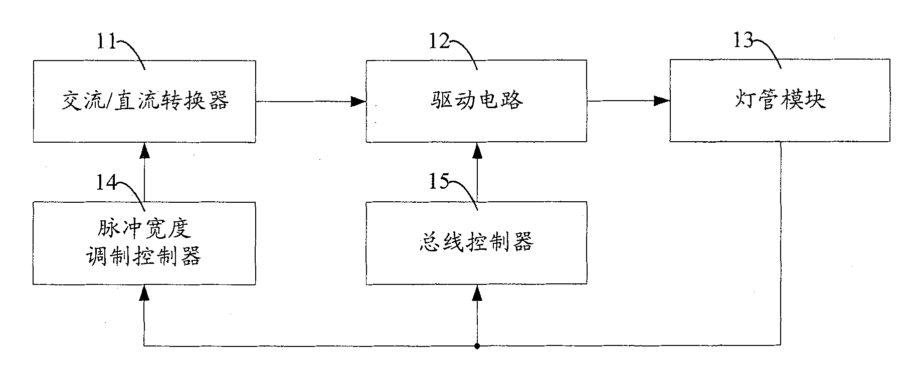
图2是本发明多灯管驱动系统第一实施例的架构图。Fig. 2 is a structure diagram of the first embodiment of the multi-lamp driving system of the present invention.
图3是本发明多灯管驱动系统第二实施例的架构图。Fig. 3 is a structure diagram of the second embodiment of the multi-lamp driving system of the present invention.
图4是本发明多灯管驱动系统第三实施例的架构图。Fig. 4 is a structure diagram of the third embodiment of the multi-lamp driving system of the present invention.
图5是本发明多灯管驱动系统第四实施例的架构图。FIG. 5 is a structure diagram of a fourth embodiment of the multi-lamp driving system of the present invention.
【具体实施方式】 【Detailed ways】
参阅图2,所示为本发明多灯管驱动系统第一实施例的架构图。Referring to FIG. 2 , it is a structure diagram of the first embodiment of the multi-lamp driving system of the present invention.
在本发明中,多灯管驱动系统包括一交流/直流转换器11,一驱动电路12,一灯管模块13,一脉冲宽度调制控制器14,以及一个总线控制器(BUS Inverter Controller)15。其中,灯管模块13包括多个灯管。In the present invention, the multi-lamp driving system includes an AC/
交流/直流转换器11用于接收交流电压,并将其转换为直流电压。The AC/
驱动电路12与交流/直流转换器11电连接,用于将接收到直流电压转换为交流电压。驱动电路12利用一开关在导通时电压通过,而关闭时电压不能通过的原理将接收到的直流电压转换为交流电压。当开关导通时,开关接收到一直流电压并输出一高电位的信号,而在当开关关闭时,由于直流电压无法通过开关而输出一低电位的信号,因此,将直流电压通过一具有周期性导通与关闭特性的开关,产生周期性的脉冲,这种周期性的脉冲即是经由驱动电路12输出的交流电压。The
在本发明的实施例中,驱动电路12是半桥式驱动电路,在本发明的其它实施例中,驱动电路12也可以使全桥式驱动电路,或者是推挽式驱动电路。In the embodiment of the present invention, the
灯管模块13与驱动电路12电连接,用于接收驱动电路12输出交流电压,点亮各个灯管。The
脉冲宽度调制控制器14与灯管模块13及交流/直流转换器11相连,用于根据灯管模块13中流经各个灯管的电流反馈信号输出一控制信号至交流/直流转换器11。交流/直流转换器11根据此控制信号改变其输出直流电压的强弱。交流/直流转换器11输出的直流电压的强弱经由驱动电路12影响灯管模块13中各个灯管的亮度。因此,当灯管模块13中各个灯管的亮度需要矫正或改变时,即,流经各个灯管的电流需要调整时,交流/直流转换器11、驱动电路12、灯管模块13及脉冲宽度调制控制器14将形成一个回路,通过回路反馈灯管模块中各个灯管的电流来改变交流/直流转换器11输出的直流电压,从而控制灯管模块13中各个灯管的亮度。The pulse
总线控制器15与灯管模块13及驱动电路12电连接,用于根据灯管模块13流经各个灯管的电流调整总线控制器15工作频率,提高驱动电路12的交流输出电压。当灯管模块13中各个灯管尚未点亮,灯管模块13与总线控制器15及驱动电路12构成一个回路,借由回路感测到灯管模块13中各个灯管没有电流,总线控制器15调整工作频率,控制驱动电路12提高输出的交流电压,点亮灯管模块13中各个灯管。The
参阅图3,所示为本发明多灯管驱动系统第二实施例的架构图。该多灯管驱动系统与本发明第一实施例的区别仅限于在第一实施例中采用交流/直流转换器11,即该多灯管驱动系统使用交流电压输入驱动多灯管,而在第二实施例中采用直流/直流转换器11’,即该多灯管驱动系统采用直流电压输入驱动多灯管。Referring to FIG. 3 , it is a structure diagram of the second embodiment of the multi-lamp driving system of the present invention. The difference between the multi-lamp driving system and the first embodiment of the present invention is only that the AC/
当驱动灯管的数量太多,而驱动电路12无法承受众多灯管所需功率时,本发明又提供驱动多个灯管模块的另一较佳实施例。When the number of lamps to be driven is too large and the
请参阅图4,是本发明驱动多个灯管模块的架构图。该电路包括多个交流/直流转换器11,21,...,N1,多个驱动电路12,22,...,N2,多个灯管模块13,23,...,N3,一多相位脉冲宽度调制控制器14’,一个总线控制器15。Please refer to FIG. 4 , which is a structure diagram of driving multiple lamp modules in the present invention. The circuit includes a plurality of AC/
交流/直流转换器N1(N=2,3,...),驱动电路N2(N=2,3,...)及灯管模块N3(N=2,3,...)连接关系与图1中所述交流/直流转换器11,驱动电路12及灯管模块13连接关系一致。Connection relation of AC/DC converter N1 (N=2, 3,...), drive circuit N2 (N=2, 3,...) and lamp module N3 (N=2, 3,...) The connection relationship between the AC/
多相位脉冲宽度调制控制器14’与交流/直流转换器N1(N=1,2,...)及灯管模块N3(N=1,2,...)电连接。总线控制器15与驱动电路N2(N=1,2,...)及灯管模块N3(N=1,2,...)电连接。The multi-phase PWM controller 14' is electrically connected to the AC/DC converter N1 (N=1, 2, ...) and the lamp module N3 (N = 1, 2, ...). The
多相位脉冲宽度调制控制器14’依照预先设定好的时序在不同的时间输出控制信号至相应的交流/直流转换器N1(N=1,2,...),控制交流/直流转换器N1(N=1,2,...)在不同的时间接收交流电压输入。The multi-phase pulse width modulation controller 14' outputs control signals to the corresponding AC/DC converters N1 (N=1, 2, ...) at different times according to the preset timing, to control the AC/DC converters N1 (N=1, 2, . . . ) receives AC voltage input at different times.
首先,多相位脉冲宽度调制控制器14’控制交流/直流转换器11接收交流电压,交流/直流转换器11将交流电压转换为直流电压。驱动电路12将直流电压转换为交流电压,用于驱动灯管模块13各个灯管。总线控制器15感测灯管模块13的电流,如果灯管模块13中没有电流,则调整其工作频率,提高驱动电路12输出的交流电压,从而点亮灯管模块13中各个灯管。First, the multi-phase PWM controller 14' controls the AC/
如果设定点亮灯管模块13中各个灯管是在多相位脉冲宽度调制控制器14’时序的第一个时间内完成,则在多相位脉冲宽度调制控制器14’时序的第N(N=2,3,...)时间内,多相位脉冲宽度调制控制器14’控制交流/直流转换器N1(N=2,3,...)接收交流电压,交流/直流转换器N1(N=2,3,...)将交流电压转换为直流电压。驱动电路N2将直流电压转换为交流电压,用于驱动灯管模块N3(N=2,3,...)各个灯管。如果总线控制器15感测到灯管模块23没有电流流过,则调整工作频率,提高驱动电路N2(N=2,3,...)输出的交流电压,从而点亮灯管模块N3(N=2,3,...)中各个灯管。If setting and lighting each lamp in the
当灯管模块N3中各个灯管的亮度需要矫正或改变时,多相位脉冲宽度调制控制器14’根据时序依次控制交流/直流转换器N1输出的直流电压,从而调节灯管模块N3中各个灯管的亮度。When the brightness of each lamp in the lamp module N3 needs to be corrected or changed, the multi-phase pulse width modulation controller 14' sequentially controls the DC voltage output by the AC/DC converter N1 according to the sequence, thereby adjusting the brightness of each lamp in the lamp module N3 tube brightness.
假设调节灯管模块13亮度在多相位脉冲宽度调制控制器14’时序的第一个时间内完成,则在多相位脉冲宽度调制控制器14’时序的第N(N=1,2,...)个时间内,交流/直流转换器N1(N=1,2,...),驱动电路N2(N=1,2,...),灯管模块N3(N=1,2,...)及多相位脉冲宽度调制控制器14’将形成一个回路,借由回路感测灯管模块N3(N=1,2,...)中各个灯管电流的反馈信号控制交流/直流转换器N1(N=1,2,...)输出的直流电压,从而达到控制灯管模块N3(N=1,2,...)中各个灯管的亮度之目的。Assuming that adjusting the brightness of the
参阅图5,所示为本发明多灯管驱动系统第四实施例的架构图。该多灯管驱动系统与本发明第三实施例的电路架构基本相同,区别仅限于第三实施例中采用交流/直流转换器N1′(N=1,2,...),即该多灯管驱动系统可以使用交流电压输入驱动多灯管,而在第二实施例中,采用直流/直流转换器N1’(N=1,2,...),即该多灯管驱动系统也可以采用直流电压输入驱动多灯管。Referring to FIG. 5 , it is a structure diagram of a fourth embodiment of the multi-lamp driving system of the present invention. The circuit architecture of the multi-lamp drive system is basically the same as that of the third embodiment of the present invention, the difference is only that the third embodiment uses an AC/DC converter N1' (N=1, 2, ...), that is, the multi-lamp The lamp driving system can use AC voltage input to drive multiple lamps, and in the second embodiment, a DC/DC converter N1' (N=1, 2, . . . ) is used, that is, the multi-lamp driving system also Multiple lamps can be driven by DC voltage input.
Claims (12)
Priority Applications (1)
| Application Number | Priority Date | Filing Date | Title |
|---|---|---|---|
| CNB2005100327353A CN100574550C (en) | 2005-01-06 | 2005-01-06 | Multi-lamp drive system |
Applications Claiming Priority (1)
| Application Number | Priority Date | Filing Date | Title |
|---|---|---|---|
| CNB2005100327353A CN100574550C (en) | 2005-01-06 | 2005-01-06 | Multi-lamp drive system |
Publications (2)
| Publication Number | Publication Date |
|---|---|
| CN1802064A CN1802064A (en) | 2006-07-12 |
| CN100574550C true CN100574550C (en) | 2009-12-23 |
Family
ID=36811737
Family Applications (1)
| Application Number | Title | Priority Date | Filing Date |
|---|---|---|---|
| CNB2005100327353A Expired - Fee Related CN100574550C (en) | 2005-01-06 | 2005-01-06 | Multi-lamp drive system |
Country Status (1)
| Country | Link |
|---|---|
| CN (1) | CN100574550C (en) |
Families Citing this family (1)
| Publication number | Priority date | Publication date | Assignee | Title |
|---|---|---|---|---|
| CN101038380B (en) * | 2006-03-16 | 2012-03-21 | 奇美电子股份有限公司 | Liquid crystal display and its power supply circuit |
Citations (3)
| Publication number | Priority date | Publication date | Assignee | Title |
|---|---|---|---|---|
| US6326740B1 (en) * | 1998-12-22 | 2001-12-04 | Philips Electronics North America Corporation | High frequency electronic ballast for multiple lamp independent operation |
| JP2002354823A (en) * | 2001-05-18 | 2002-12-06 | Advanced Display Inc | Pwm system inverter |
| CN1096822C (en) * | 1994-02-15 | 2002-12-18 | 松下电工株式会社 | High-pressure discharge lamp lighting device |
-
2005
- 2005-01-06 CN CNB2005100327353A patent/CN100574550C/en not_active Expired - Fee Related
Patent Citations (3)
| Publication number | Priority date | Publication date | Assignee | Title |
|---|---|---|---|---|
| CN1096822C (en) * | 1994-02-15 | 2002-12-18 | 松下电工株式会社 | High-pressure discharge lamp lighting device |
| US6326740B1 (en) * | 1998-12-22 | 2001-12-04 | Philips Electronics North America Corporation | High frequency electronic ballast for multiple lamp independent operation |
| JP2002354823A (en) * | 2001-05-18 | 2002-12-06 | Advanced Display Inc | Pwm system inverter |
Non-Patent Citations (1)
| Title |
|---|
| 数字控制金卤灯用电子镇流器研究. 金亦青.浙江大学硕士论文. 2004 * |
Also Published As
| Publication number | Publication date |
|---|---|
| CN1802064A (en) | 2006-07-12 |
Similar Documents
| Publication | Publication Date | Title |
|---|---|---|
| CN101668371B (en) | Apparatus for lighting LEDs | |
| JP5470150B2 (en) | Switching power supply control circuit, control method, and light emitting device and electronic apparatus using them | |
| US7151346B2 (en) | Method and apparatus for optimizing power efficiency in light emitting device arrays | |
| CN101589539B (en) | Load driving circuit, integrated circuit, dc-dc converter and load driving method | |
| CN101356717B (en) | Power supply, lighting control device and display device | |
| US7489533B2 (en) | Frequency feedforward for constant light output in backlight inverters | |
| CN104333933B (en) | Light-emitting diode driving device and light-emitting diode lighting system using the same | |
| CN1575082A (en) | Backlight inverter for liquid crystal display panel of asynchronous pulse width modulation driving type | |
| WO2014187015A1 (en) | Led backlight driving circuit, liquid crystal display apparatus, and driving method | |
| CN102543005A (en) | Reference voltage generating circuit and LED driver circuit having the same therein | |
| CN100574550C (en) | Multi-lamp drive system | |
| CN101018439B (en) | Discharge lamp driving device | |
| KR100785161B1 (en) | Multi-lamp driving system | |
| CN103150996B (en) | LED driver equipment | |
| CN100341385C (en) | Driving discharge lamp tube and its dimming control device | |
| KR100526240B1 (en) | Inverter for cold cathode fluorescent lamp of complexing dimming type | |
| CN101038380B (en) | Liquid crystal display and its power supply circuit | |
| TWI313573B (en) | Discharge lamp driving device | |
| CN100511953C (en) | Conversion circuit for driving full-bridge type commutation by using push-pull type pulse wave controller | |
| US20070164690A1 (en) | Discharge lamp driving device | |
| TWI361022B (en) | A driving system to control power supply to a ccfl | |
| CN114974145A (en) | LED driving circuit and method | |
| KR20060010012A (en) | Inverter for external electrode lamp | |
| CN101765285A (en) | Lighting tube drive device | |
| HK1118667A1 (en) | Power supply circuit for liquid crystal display backlight and method thereof |
Legal Events
| Date | Code | Title | Description |
|---|---|---|---|
| C06 | Publication | ||
| PB01 | Publication | ||
| C10 | Entry into substantive examination | ||
| SE01 | Entry into force of request for substantive examination | ||
| C14 | Grant of patent or utility model | ||
| GR01 | Patent grant | ||
| C17 | Cessation of patent right | ||
| CF01 | Termination of patent right due to non-payment of annual fee |
Granted publication date: 20091223 Termination date: 20140106 |