CN100571651C - A kind of bionic tooth implant - Google Patents
A kind of bionic tooth implant Download PDFInfo
- Publication number
- CN100571651C CN100571651C CNB2007100488509A CN200710048850A CN100571651C CN 100571651 C CN100571651 C CN 100571651C CN B2007100488509 A CNB2007100488509 A CN B2007100488509A CN 200710048850 A CN200710048850 A CN 200710048850A CN 100571651 C CN100571651 C CN 100571651C
- Authority
- CN
- China
- Prior art keywords
- root
- hole
- oblique
- parent
- daughter
- Prior art date
- Legal status (The legal status is an assumption and is not a legal conclusion. Google has not performed a legal analysis and makes no representation as to the accuracy of the status listed.)
- Expired - Fee Related
Links
Images




Classifications
-
- A—HUMAN NECESSITIES
- A61—MEDICAL OR VETERINARY SCIENCE; HYGIENE
- A61C—DENTISTRY; APPARATUS OR METHODS FOR ORAL OR DENTAL HYGIENE
- A61C8/00—Means to be fixed to the jaw-bone for consolidating natural teeth or for fixing dental prostheses thereon; Dental implants; Implanting tools
- A61C8/0018—Means to be fixed to the jaw-bone for consolidating natural teeth or for fixing dental prostheses thereon; Dental implants; Implanting tools characterised by the shape
-
- A—HUMAN NECESSITIES
- A61—MEDICAL OR VETERINARY SCIENCE; HYGIENE
- A61C—DENTISTRY; APPARATUS OR METHODS FOR ORAL OR DENTAL HYGIENE
- A61C8/00—Means to be fixed to the jaw-bone for consolidating natural teeth or for fixing dental prostheses thereon; Dental implants; Implanting tools
- A61C8/001—Multiple implanting technique, i.e. multiple component implants introduced in the jaw from different directions
-
- A—HUMAN NECESSITIES
- A61—MEDICAL OR VETERINARY SCIENCE; HYGIENE
- A61C—DENTISTRY; APPARATUS OR METHODS FOR ORAL OR DENTAL HYGIENE
- A61C8/00—Means to be fixed to the jaw-bone for consolidating natural teeth or for fixing dental prostheses thereon; Dental implants; Implanting tools
- A61C8/0018—Means to be fixed to the jaw-bone for consolidating natural teeth or for fixing dental prostheses thereon; Dental implants; Implanting tools characterised by the shape
- A61C8/0037—Details of the shape
- A61C8/0043—Details of the shape having more than one root
-
- A—HUMAN NECESSITIES
- A61—MEDICAL OR VETERINARY SCIENCE; HYGIENE
- A61C—DENTISTRY; APPARATUS OR METHODS FOR ORAL OR DENTAL HYGIENE
- A61C8/00—Means to be fixed to the jaw-bone for consolidating natural teeth or for fixing dental prostheses thereon; Dental implants; Implanting tools
- A61C8/0048—Connecting the upper structure to the implant, e.g. bridging bars
- A61C8/005—Connecting devices for joining an upper structure with an implant member, e.g. spacers
-
- A—HUMAN NECESSITIES
- A61—MEDICAL OR VETERINARY SCIENCE; HYGIENE
- A61C—DENTISTRY; APPARATUS OR METHODS FOR ORAL OR DENTAL HYGIENE
- A61C8/00—Means to be fixed to the jaw-bone for consolidating natural teeth or for fixing dental prostheses thereon; Dental implants; Implanting tools
- A61C8/0048—Connecting the upper structure to the implant, e.g. bridging bars
- A61C8/005—Connecting devices for joining an upper structure with an implant member, e.g. spacers
- A61C8/0066—Connecting devices for joining an upper structure with an implant member, e.g. spacers with positioning means
-
- A—HUMAN NECESSITIES
- A61—MEDICAL OR VETERINARY SCIENCE; HYGIENE
- A61C—DENTISTRY; APPARATUS OR METHODS FOR ORAL OR DENTAL HYGIENE
- A61C8/00—Means to be fixed to the jaw-bone for consolidating natural teeth or for fixing dental prostheses thereon; Dental implants; Implanting tools
- A61C8/0048—Connecting the upper structure to the implant, e.g. bridging bars
- A61C8/005—Connecting devices for joining an upper structure with an implant member, e.g. spacers
- A61C8/0069—Connecting devices for joining an upper structure with an implant member, e.g. spacers tapered or conical connection
-
- A—HUMAN NECESSITIES
- A61—MEDICAL OR VETERINARY SCIENCE; HYGIENE
- A61C—DENTISTRY; APPARATUS OR METHODS FOR ORAL OR DENTAL HYGIENE
- A61C8/00—Means to be fixed to the jaw-bone for consolidating natural teeth or for fixing dental prostheses thereon; Dental implants; Implanting tools
- A61C8/0048—Connecting the upper structure to the implant, e.g. bridging bars
- A61C8/005—Connecting devices for joining an upper structure with an implant member, e.g. spacers
- A61C8/0054—Connecting devices for joining an upper structure with an implant member, e.g. spacers having a cylindrical implant connecting part
-
- A—HUMAN NECESSITIES
- A61—MEDICAL OR VETERINARY SCIENCE; HYGIENE
- A61C—DENTISTRY; APPARATUS OR METHODS FOR ORAL OR DENTAL HYGIENE
- A61C8/00—Means to be fixed to the jaw-bone for consolidating natural teeth or for fixing dental prostheses thereon; Dental implants; Implanting tools
- A61C8/0048—Connecting the upper structure to the implant, e.g. bridging bars
- A61C8/005—Connecting devices for joining an upper structure with an implant member, e.g. spacers
- A61C8/0068—Connecting devices for joining an upper structure with an implant member, e.g. spacers with an additional screw
Landscapes
- Health & Medical Sciences (AREA)
- Oral & Maxillofacial Surgery (AREA)
- Orthopedic Medicine & Surgery (AREA)
- Dentistry (AREA)
- Epidemiology (AREA)
- Life Sciences & Earth Sciences (AREA)
- Animal Behavior & Ethology (AREA)
- General Health & Medical Sciences (AREA)
- Public Health (AREA)
- Veterinary Medicine (AREA)
- Dental Prosthetics (AREA)
Abstract
The invention discloses a kind of bionic tooth implant and method for implantation thereof.This bionic tooth implant comprises fixedly root, cervical region and abutment portion, described fixedly root comprises parent root and at least one piece of daughter root, the diameter of daughter root is less than the diameter of parent root, oblique hole in parent root or the cervical region body to its periphery break-through, or oblique hole simultaneously in parent root and the cervical region body to its periphery break-through, every piece of oblique being placed in the oblique hole in daughter root upper end.Compared with prior art, the present invention possesses firm performance of good initial stage and anti-revolving of initial stage prevents turning round ability, can strengthen implantation body with the jawbone contact area, improves the success rate of the stressed at once success rate of plantation at once and long-term firm effective performance mastication; The method for implantation of this bionic tooth implant is the same with the implant surgery operation of existing implantation body, all is to operate by an implantable port, the simple and practical property of operational approach when having kept the implanted jawbone of present dental implant, but what obtain is the clear superiority of many plantations.
Description
Technical field
The present invention relates to artificial tooth system, particularly relate to a kind of bionic tooth implant that jawbone serves as artificial tooth root of implanting.
Background technology
From the comfort level and the long-term steadiness of clinical practice, odontologist uses the most successful implantation body at most at present, and the cylinder taper rotation that is likeness in form natural tooth root form is with regard to bit-type implantation body.This kind is shaped as axisymmetric cylindricality or conical implantation body, generally all there is the rotatable screw thread that is located in the jawbone bone hole that has prepared on its surface, thereby can obtain certain initial stage steadiness, in addition the various increases that implant surface is carried out its with the means of the biological contact area of jawbone (as surface coarsening, titanium slurry spraying etc.) enforcement, this type of implantation body generally uses in the world at present.
Notification number is CN1826089A, and the patent of invention of " tooth implant " by name discloses a kind of tooth implant that is made of staple portion, cervical region and abutment portion.This patented technology is that typical cylinder taper rotation is with regard to bit-type implantation body, because it is single cylinder or bullet, can not form the mutual traction action between a plurality of roots of the tooth of similar natural teeth and bring into play the anti-anti-function of turning round of revolving, only rely on the limited initial stage of implant surface screw thread firmly to act on, the tooth that is difficult to resist on the implantation body basis disturbs the various torsion that implantation body produces when laboratory rodent chow.Therefore, present most implantation body still need wait for the some months time behind implanted human body jawbone, can not adorn the stressed enforcement masticatory function of tooth at once, otherwise can destroy the organic synosteosis of implantation body, finally cause implantation body to become flexible and make planting failure with the jawbone contact interface.
Summary of the invention
Purpose of the present invention is exactly at the deficiencies in the prior art, and a kind of bionic tooth implant of similar natural tooth root is provided.This bionic tooth implant not only possesses firm performance of good initial stage and anti-revolving of initial stage prevents turning round ability, and can strengthen implantation body with the jawbone contact area, improves the stressed at once and long-term firm effectively success rate of plantation at once.
For achieving the above object, technical scheme of the present invention is as follows:
The bionic tooth implant that the present invention proposes comprises fixedly root, cervical region and abutment portion.Described fixedly root comprises parent root and at least one piece of daughter root, and the diameter of daughter root is less than the diameter of parent root; Oblique hole in parent root or the cervical region body to its periphery break-through, or oblique hole simultaneously in parent root and the cervical region body to its periphery break-through, every piece of oblique being placed in the oblique hole in daughter root upper end.Oblique hole simultaneously in parent root and the cervical region body to its periphery break-through, be oblique hole in parent root and the cervical region body outwards break-through parent root and cervical region periphery intersection, or some oblique hole in the parent root body to its periphery break-through simultaneously other oblique holes in the cervical region body to its periphery break-through, or some oblique hole in parent root and the cervical region body outwards break-through parent root and cervical region periphery intersection simultaneously other oblique holes in parent root or the cervical region body to its periphery break-through.Fixedly root structure has like this formed at least two multirooted teeth implant retention mechanism that the maintenance root is above, and this bionic tooth implant can not only form the distribution of many rhizoplanes formula drag, bring into play the mutual restraining function between root and the root and resist twisted interference, can also form many three-dimensional drags distributes, analyze from physiological mechanics, this drag physiological feature of convergence human body natural teeth " area occupied is big more between the root of the tooth; be beneficial to the firm of tooth more " that distributes, thereby significantly strengthened the initial stage steadiness of implantation body and long-term firm.Mutual traction action between many more meets the jawbone physiological requirement to the stimulation of jawbone bone fibres, make jawbone osseous tissue hypertrophy more, absorb still less, efficient hardening implantation body combines with osseous tissue.
Described cervical region is positioned at the parent root top, is connected as a single entity with parent root.Inwardly there is a taper hole on the cervical region top, and an internal square hole or interior three square holes are arranged at the taper hole bottom, and internal square hole or interior three square holes bottom are extended a screw, the vertical break-through of screw or not break-through parent root bottom vertically.Described internal square hole or interior three square hole sidepieces have oblique hole, or described taper hole sidepiece has oblique hole, or taper hole and internal square hole sidepiece have oblique hole simultaneously, or taper hole and interior three square hole sidepieces have oblique hole simultaneously.Taper hole and internal square hole sidepiece have oblique hole simultaneously, be that open at taper hole and internal square hole sidepiece intersection in oblique hole, or some oblique hole opens at the taper hole sidepiece and opens at the internal square hole sidepiece in other oblique holes simultaneously, or some oblique hole is opened at taper hole and internal square hole sidepiece intersection and opened at taper hole or internal square hole sidepiece in other oblique holes simultaneously; Taper hole and interior three square hole sidepieces have oblique hole simultaneously, be that open at taper hole and interior three square hole sidepiece intersections in oblique hole, or some oblique hole opens at the taper hole sidepiece and opens at interior three square hole sidepieces in other oblique holes simultaneously, or some oblique hole is opened at taper hole and interior three square hole sidepiece intersections and opened at taper hole or interior three square hole sidepieces in other oblique holes simultaneously.Described oblique hole break-through parent root or cervical region periphery, or while break-through parent root and cervical region periphery, the number in oblique hole is at least 1, the quantity of daughter root is consistent with the quantity in oblique hole, every piece of oblique being placed in the oblique hole in daughter root upper end.Center, every piece of daughter root upper surface inwardly has an axial little internal square hole, and the daughter root upper end axially has a dovetail along parent root.Abutment portion comprises the corresponding cone that is embedded in the described taper hole, along the upwardly extending protuberance of cone, and along downward outer tetragonal body or the outer tripartite body that extends of cone.Described outer tetragonal body is embedded in the described internal square hole, or described outer tripartite body is embedded in described interior three square holes, described outer tetragonal body or outer tripartite body side surface are provided with the dovetail slot, and the quantity of dovetail slot is consistent with daughter root quantity, and each dovetail slot engages with dovetail on every piece of daughter root.The abutment portion center offers the logical hole that holds of a ganoid bolt, and the base station bolt is rotated with in the screw of parent root by the logical hole that holds.The dovetail that many root architectures of described bionic tooth implant at first rely on the daughter root upper end with connect after the dovetail slot of outer tetragonal body of abutment portion or outer tripartite body side surface engages mutually admittedly, form the function entity of being close to the phase embedding and rely on the base station bolt to be rotated with and then in the parent root screw.
Described internal square hole or interior three square holes are tapered to the parent root direction from cervical region, chimeric with it outer tetragonal body or outer tripartite body are tapered downwards from cone, promptly outer tetragonal body or outer tripartite body are thicker near an end of cone, end away from cone is thinner, can make the tight more easily chimeric company of abutment portion and parent root solid like this.The width of described dovetail axially becomes big downwards gradually along parent root, the end width away from the daughter root bottom that is dovetail is less, end width near the daughter root bottom is bigger, the width of Ka He dovetail slot becomes big from top to bottom gradually with it, promptly become big gradually to the cone rightabout, just the dovetail slot is less near an end width of cone, and is bigger away from an end width of cone, abutment portion and daughter root closely engaged more easily connect admittedly.Between parent root and abutment portion, between cervical region and the abutment portion, the tripartite connected mode of gradually thin taper four directions or taper, be taper hole and cone, the chimeric connected mode between thin internal square hole and gradually thin outer tetragonal body or gradually thin interior three square holes and the gradually thin outer tripartite body gradually, guaranteed the closed structure fully isolated with the external world.Described bionic tooth implant is by cervical region and the integrally formed mode of parent root, abutment portion and cervical region and the fixing tight chimeric mode of root, and screw thread connects solid mode, and finally be combined into by the fixing common synthetic function entity of root, cervical region and abutment portion.
Has screw thread on the described parent root periphery, screw thread stricture of vagina tooth section shape is asymmetric trapezoidal, the upper surface is flat, the lower surface is more oblique, stricture of vagina tooth upper surface is 90 degree-120 degree near the stricture of vagina increment face and the angle α between the parent root appearance of cervical region promptly, wherein preferred 102 degree, stricture of vagina tooth lower surface are 123 degree away from the stricture of vagina increment face and the angle β between the parent root appearance of cervical region promptly.Described daughter root bottom periphery has screw thread, screw thread stricture of vagina tooth section shape is asymmetric trapezoidal, the upper surface is flat, the lower surface is more oblique, stricture of vagina tooth upper surface is 90 degree-120 degree near the stricture of vagina increment face and the angle α between the daughter root appearance of daughter root upper surface promptly, wherein preferred 102 degree, stricture of vagina tooth lower surface are 123 degree away from the stricture of vagina increment face and the angle β between the daughter root appearance of daughter root upper surface promptly.When the vertical break-through parent root of described screw bottom, the base station bolt is rotated with back its following transverse plane that puts in place and protrudes in transverse plane under the parent root.Because the deboost that the base station bolt is produced after being rotated with and putting in place makes the oppositely tight lock in screw thread stricture of vagina tooth upper surface and mandibular organization of parent root and daughter root bottom outer surface, strengthen anti-the revolving of initial stage of described bionic tooth implant and prevented turning round function, for plantation at once adorn at once stressed universal of tooth provide may, provide possible for ensure that implantation body also can form combine with the normal bone of mandibular organization under stressed (load) situation at once.
The outer surface of parent root and daughter root is all handled through surface coarsening.Parent root bottom and daughter root bottom are tapered downwards with the tapering between 1 degree-30 degree scopes, form the plane or the conical surface in the lower surface.The tapered root that parent root and daughter root are gradually thin is more prone to the preparation boring on the jawbone.Parent root bottom and daughter root bottom have at least one lobate cutting groove respectively.Described lobate cutting groove has guide effect, makes implantation body implant easier putting in place.
Angle number of degrees excursion between parent root and the daughter root is 13 degree-26 degree, wherein preferred 21 degree.By reducing the stagger angle of daughter root, can form the curved root architecture of flat of similar natural front tooth in appearance with parent root.By changing the corner dimension between parent root and the daughter root, make the form scope of described bionic tooth implant almost can contain fully and form similar natural teeth from the front tooth to the canine tooth again to bicuspid at last to the root structures form of backteeth, thereby stressed, the drag mode that makes described tooth implant convergence nature physiological status more.
Described protuberance is a cylinder body shape, and its outer surface is provided with at least two circle arc grooves, and described arc groove is used for fixing artificial tooth.Described cervical region is up big and down small truncated cone-shaped, and is promptly less near an end diameter of parent root, bigger away from an end diameter of parent root.Described cervical region outer surface is smooth.
Owing to adopted daughter root, the planting patterns that parent root is staggered, during the plantation of described bionic tooth implant can according to before the art to the sclerotin form of jawbone host site, quality, the anatomical structure investigation, select daughter root flexibly, the length of parent root, size, direction and staggered position thereof, the angle of inclination of stagger angle and whole implantation body, thereby form multiple plane and spatial many combinative structurees, and then widen potential plantation space on the jawbone, can effectively avoid again simultaneously can not be impaired on the jawbone pipe, the chamber, anatomical structures such as hole, improve the plantation success rate, enlarge plantation indication scope.Change according to the conditions such as the strength of materials of making described bionic tooth implant can be adjusted into interior hexagonal hole with internal square hole in the described bionic tooth implant parent root or interior three square holes, and outer tetragonal body or the outer tripartite body of adjusting abutment portion are outer hexahedron.
The method for implantation of described bionic tooth implant is as follows:
(1) hole pre-determining on the jawbone that needs to plant with boring bar tool, the depth in hole is with diameter and need the parent root implanted consistent.
(2) use tapping tool in the inwall tapping of above-mentioned bone hole, form the screwed hole that matches with parent root appearance screw thread.
(3) with the internal square hole or interior three square holes of instrument connection parent root, parent root is screwed in above-mentioned bone hole.
(4) with the small bore instrument of diameter with daughter root, the process taper hole is the oblique hole of break-through oblique drilling hole in jawbone again, and the degree of depth is implanted the degree of depth of jawbone with daughter root; Also need go the tapping of bone hole if desired.
(5) with behind the little tetragonal body instrument connection daughter root, daughter root is screwed in above-mentioned bone hole in the oblique hole of break-through again through taper hole, and guarantee that daughter root upper surface and parent root internal square hole or interior three square hole planes are on the same horizontal plane.
(6) place abutment portion downwards from taper hole, the dovetail slot of outer tetragonal body or outer tripartite body side surface is inserted down smoothly and formed closely chimeric with dovetail.
(7) screwing the base station bolt makes each part mentioned above form fastening integral body.
Compared with prior art, the invention has the beneficial effects as follows: possess anti-revolving of firm performance of good initial stage and initial stage and prevent turning round ability, can strengthen implantation body with the jawbone contact area, improve the success rate of stressed at once success rate of plantation at once and long-term firm effectively performance mastication.The method for implantation of this bionic tooth implant is the same with the implant surgery operation of existing implantation body, all is to operate by an implantable port, the simple and practical property of operational approach when having kept the implanted jawbone of present dental implant, but what obtain is the clear superiority of many plantations.No matter parent root or daughter root, still adopt and axially rotate into planting patterns in place, operate not only simple and fast, and can experience at once by screw thread and revolve knot and the fastening feel of implantation body in jawbone of generation, especially after screwing in daughter root, all the more significantly the power admittedly of opening of mutual tractive between screw-tightened power and the Duo Gen gives the patient with strong confidence.
Description of drawings
Fig. 1 is the axonometric chart that has the described bionic tooth implant of 2 pieces of daughter root.
Fig. 2 is the axonometric chart of parent root and cervical region.
Fig. 3 has the bionic tooth implant parent root of internal square hole and the cutaway view of cervical region.
Fig. 4 is the vertical vertical view of bionic tooth implant cervical region that has internal square hole.
Fig. 5 has the bionic tooth implant parent root of internal square hole and the internal structure axonometric chart of cervical region.
Fig. 6 is the axonometric chart of daughter root.
Fig. 7 is the internal structure axonometric chart after bionic tooth implant parent root, cervical region and the daughter root assembling that has internal square hole.
Fig. 8 is the axonometric chart that has the abutment portion of outer tetragonal body.
Fig. 9 is the mutual chimeric axonometric chart of daughter root and the abutment portion that has outer tetragonal body.
Figure 10 is the internal structure axonometric chart after parent root, daughter root, cervical region and the abutment portion assembling that has the bionic tooth implant of internal square hole.
Figure 11 is the parent root, daughter root, cervical region and the abutment portion that have the bionic tooth implant of internal square hole and the internal structure axonometric chart after the base station bolts assemblies.
Figure 12 is the axonometric chart that has the described bionic tooth implant of 3 pieces of daughter root.
Figure 13 has the bionic tooth implant parent root of interior three square holes and the axonometric chart of cervical region.
Figure 14 has the bionic tooth implant parent root of interior three square holes and the internal structure axonometric chart of cervical region.
Figure 15 is the vertical vertical view of bionic tooth implant cervical region that has interior three square holes.
Figure 16 is the vertical view that has the described bionic tooth implant of 3 pieces of daughter root.
Figure 17 is the axonometric chart that has the abutment portion of outer tripartite body.
Figure 18 is the internal structure axonometric chart after parent root, daughter root, cervical region and the abutment portion assembling that has the bionic tooth implant of interior three square holes.
Figure 19 is the axonometric chart of bionic tooth implant that has the curved root of imitative flat of 1 piece of daughter root.
Figure 20 is the axonometric chart that the parent root that has 1 piece of daughter root is the oblique implantation of bionic tooth implant of column.
Figure 21 is the axonometric chart that the parent root that has 1 piece of daughter root is the oblique implantation of bionic tooth implant of taper.
Figure 22 is the axonometric chart that has the short parent root bionic tooth implant of 2 pieces of daughter root.
Figure 23 is the axonometric chart that has the short parent root bionic tooth implant of 3 pieces of daughter root.
Figure 24 is the axonometric chart that has the short parent root bionic tooth implant of 4 pieces of daughter root.
Figure 25 be have in the implanted human body jawbone of bionic tooth implant of 2 pieces of daughter root and load onto tooth after sketch map.
Number in the figure is as follows:
1 fixing root 2 cervical regions
3 abutment portion, 4 parent root
5 daughter root, 6 taper holes
7 internal square holes, 8 screws
9 oblique holes, 10 little internal square holes
11 dovetails, 12 cones
13 protuberances, 14 outer tetragonal bodies
The logical hole that holds of 15 dovetail slot 16s
Three square holes in the 17 base station bolts 18
19 outer tripartite body 20 screw threads
21 grooves, 22 lobate cutting grooves
24 daughter root upper surfaces, 23 daughter root bottoms
25 parent root bottoms, 26 artificial teeth
27 gingivas, 28 jawbones
The specific embodiment
Below in conjunction with accompanying drawing, the preferred embodiments of the present invention are further described.
Embodiment one
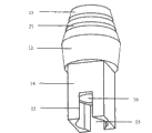
As Fig. 1, Fig. 2, Fig. 3, Fig. 4, Fig. 5, Fig. 6, Fig. 7, Fig. 8, Fig. 9, Figure 10, Figure 11, shown in Figure 25.Make the parent root 4 of tooth implant, its diameter is 4.8mm, has screw thread 20 on its periphery, and screw thread 20 stricture of vagina tooth section shapes are asymmetric trapezoidal, angle α between stricture of vagina tooth upper surface and parent root 4 appearances is 102 degree, and the angle β between stricture of vagina tooth lower surface and parent root 4 appearances is 123 degree.Cervical region 2 is positioned at the top of parent root 4, is connected as a single entity with parent root 4; Cervical region 2 is up big and down small truncated cone-shaped, and is promptly less near an end diameter of parent root 4, bigger away from an end diameter of parent root 4; Cervical region 2 outer surfaces are smooth.A taper hole 6 is inwardly offered on cervical region 2 tops, taper hole 6 bottoms have one from cervical region 2 to the tapered internal square hole 7 of parent root 4 directions, internal square hole 7 bottoms are extended a screw 8 vertically, screw 8 vertical break-through parent root 4 bottoms.Internal square hole 7 sidepiece symmetries have 2 oblique holes 9, the periphery of oblique hole 9 break-through parent root 4; Make 2 pieces of daughter root 5, the diameter of daughter root 5 is 2mm, every piece of oblique being placed in the oblique hole 9 in daughter root 5 upper ends.24 centers, every piece of daughter root 5 upper surfaces inwardly have an axial little internal square hole 10, and daughter root 5 upper ends axially have a dovetail 11 along parent root 4, and its width axially becomes big downwards gradually along parent root 4; Daughter root bottom 23 peripheries have screw thread 20, and screw thread 20 stricture of vagina tooth section shapes are asymmetric trapezoidal, and the angle α between stricture of vagina tooth upper surface and daughter root 5 appearances is 102 degree, and the angle β between stricture of vagina tooth lower surface and daughter root 5 appearances is 123 degree.This parent root 4 and 2 pieces of daughter root 5 common fixedly roots 1 of forming described bionic tooth implant.Abutment portion 3 comprises the corresponding cone 12 that is embedded in the taper hole 6, along cone 12 upwardly extending protuberances 13, and along the cone 12 downward outer tetragonal bodies 14 that extend.Protuberance 13 be shaped as cylinder body shape, outer surface is provided with two circle arc grooves 21; Outer tetragonal body 14 is tapered downwards from cone 12, is embedded in the internal square hole 7; Outer tetragonal body 14 sides are provided with 2 symmetric dovetail slots 15, and its width becomes greatly gradually to cone 12 rightabouts, and each dovetail slot 15 engages with a dovetail 11.Abutment portion 3 centers offer the logical hole 16 that holds of a ganoid bolt, and base station bolt 17 is rotated with in the screw 8 of parent root 4 by the logical hole 16 that holds, and the following transverse plane that is rotated with the back base station bolt 17 that puts in place protrudes in 4 times transverse planes of parent root.
The outer surface of parent root 4 and daughter root 5 is all handled through surface coarsening.Parent root bottom 25 and daughter root bottom 23 all are tapered downwards with the tapering of 30 degree, and parent root 4 all becomes the plane in the lower surface with daughter root 5.Parent root bottom 25 and daughter root bottom 23 evenly have 3 lobate cutting grooves 22 respectively.Angle between parent root 4 and the daughter root 5 is 21 degree.
With the bionic tooth implant that makes by in the following method for implantation implant patient jawbone: at first, hole pre-determining on the jawbone that needs to plant with boring bar tool; Then, in the inwall tapping of above-mentioned bone hole, form the screwed hole that matches with parent root 4 appearance screw threads 20 with tapping tool; Then, connect internal square hole 7, parent root 4 is screwed in above-mentioned bone hole with instrument; Then, with the small bore instrument of diameter with daughter root 5, process taper hole 6 is the oblique hole 9 of break-through oblique drilling hole in jawbone again, and the degree of depth is implanted the degree of depth of jawbones with daughter root 5; And then, behind little tetragonal body instrument connection daughter root 5, daughter root 5 is screwed in above-mentioned bone hole in the oblique hole 9 of break-through again through taper holes 6, and guarantee that daughter root upper surface 24 and parent root 4 internal square holes 7 planes are on the same horizontal plane; Then, from the taper hole 6 downward abutment portion 3 of placing, that outer tetragonal body 14 lateral dovetail slots 15 are down slotting smoothly and closely chimeric with dovetail 11 formation; At last, screwing base station bolt 17 makes each part mentioned above form fastening integral body.Behind the described bionic tooth implant implantation success, fixedly root 1 is positioned at patient's jawbone 28, and cervical region 2 is positioned at patient's gum 27, the artificial tooth 26 of assembling on the abutment portion 3.
Embodiment two
As Figure 12, Figure 13, Figure 14, Figure 15, Figure 16, Figure 17, shown in Figure 180.Make the parent root 4 of tooth implant, its diameter is 4.8mm, has screw thread 20 on its periphery, and screw thread 20 stricture of vagina tooth section shapes are asymmetric trapezoidal, angle α between stricture of vagina tooth upper surface and parent root 4 appearances is 90 degree, and the angle β between stricture of vagina tooth lower surface and parent root 4 appearances is 123 degree.Cervical region 2 is positioned at the top of parent root 4, is connected as a single entity with parent root 4; Cervical region 2 is up big and down small truncated cone-shaped, and is promptly less near an end diameter of parent root 4, bigger away from an end diameter of parent root 4; Cervical region 2 outer surfaces are smooth.A taper hole 6 is inwardly offered on cervical region 2 tops, and taper hole 6 bottoms have one from cervical region 2 three square holes 18 in parent root 4 directions are tapered, and interior three square holes 18 bottoms are extended a screw 8 vertically, screw 8 vertical break-through parent root 4 bottoms.Interior three square holes, 18 sidepieces evenly have 3 oblique holes 9, the periphery of oblique hole 9 break-through parent root 4; Make 3 pieces of daughter root 5, the diameter of daughter root 5 is 2mm, and every piece of oblique being placed in the oblique hole 9 in daughter root 5 upper ends constitutes the three-dimensional many root architectures of 360 degree.24 centers, every piece of daughter root 5 upper surfaces inwardly have an axial little internal square hole 10, and daughter root 5 upper ends axially have a dovetail 11 along parent root 4, and its width axially becomes big downwards gradually along parent root 4; Daughter root bottom 23 peripheries have screw thread 20, and screw thread 20 stricture of vagina tooth section shapes are asymmetric trapezoidal, and the angle α between stricture of vagina tooth upper surface and daughter root 5 appearances is 100 degree, and the angle β between stricture of vagina tooth lower surface and daughter root 5 appearances is 123 degree.This parent root 4 and 3 pieces of daughter root 5 common fixedly roots 1 of forming described bionic tooth implant.Abutment portion 3 comprises the corresponding cone 12 that is embedded in the taper hole 6, along cone 12 upwardly extending protuberances 13, and along the cone 12 downward outer tripartite bodies 19 that extend.Protuberance 13 be shaped as cylinder body shape, outer surface is provided with 2 circle arc grooves 21; Outer tripartite body 19 is tapered downwards from cone 12, is embedded in interior three square holes 18; Outer tripartite body 19 sides evenly are provided with 3 dovetail slots 15, and its width becomes greatly gradually to cone 12 rightabouts, and each dovetail slot 15 engages with a dovetail 11.Abutment portion 3 centers offer the logical hole 16 that holds of a bolt, and base station bolt 17 is rotated with in the screw 8 of parent root 4 by the logical hole 16 that holds, and the following transverse plane that is rotated with the back base station bolt 17 that puts in place protrudes in 4 times transverse planes of parent root.
The outer surface of parent root 4 and daughter root 5 is all handled through surface coarsening.Parent root bottom 25 and daughter root bottom 23 all are tapered downwards with the tapering of 30 degree, and parent root 4 all becomes the plane in the lower surface with daughter root 5.Parent root bottom 25 and daughter root bottom 23 have 2 lobate cutting grooves 22.Angle between parent root 4 and the daughter root 5 is 21 degree.
With the bionic tooth implant that makes by in the following method for implantation implant patient jawbone: at first, hole pre-determining on the jawbone that needs to plant with boring bar tool; Then, in the inwall tapping of above-mentioned bone hole, form the screwed hole that matches with parent root 4 appearance screw threads 20 with tapping tool; Then, connect interior three square holes 18, parent root 4 is screwed in above-mentioned bone hole with instrument; Then, with the small bore instrument of diameter with daughter root 5, process taper hole 6 is the oblique hole 9 of break-through oblique drilling hole in jawbone again, and the degree of depth is implanted the degree of depth of jawbones with daughter root 5; And then, behind little tetragonal body instrument connection daughter root 5, daughter root 5 is screwed in above-mentioned bone hole in the oblique hole 9 of break-through again through taper holes 6, and guarantee that three square holes, 18 planes are on the same horizontal plane in daughter root upper surface 24 and the parent root 4; Then, from the taper hole 6 downward abutment portion 3 of placing, that outer tripartite body 19 lateral dovetail slots 15 are down slotting smoothly and closely chimeric with dovetail 11 formation; At last, screwing base station bolt 17 makes each part mentioned above form fastening integral body.Behind the described bionic tooth implant implantation success, fixedly root 1 is positioned at patient's jawbone 28, and cervical region 2 is positioned at patient's gum 27, the artificial tooth 26 of assembling on the abutment portion 3.
Embodiment three
As shown in figure 19.The place identical with embodiment one be repeated description no longer, and difference is: screw thread 20 stricture of vagina tooth upper surfaces on parent root 4 peripheries and the angle α between parent root 4 appearances are 120 degree.Internal square hole 7 sidepieces have 1 oblique hole 9, the periphery of oblique hole 9 break-through parent root 4; Make 1 piece of daughter root 5, its upper end is oblique to be placed in the oblique hole 9.The screw thread 20 stricture of vagina tooth upper surfaces of daughter root bottom 23 peripheries and the angle α between daughter root 5 appearances are 110 degree.Outer tetragonal body 14 sides are provided with 1 dovetail slot 15, and dovetail slot 15 engages with dovetail 11.Angle between parent root 4 and the daughter root 5 is 13 degree.
Embodiment four
As shown in figure 20.The place identical with embodiment one be repeated description no longer, and difference is: parent root 4 tilts, and abutment portion 3 is the angle base station.Screw thread 20 stricture of vagina tooth upper surfaces on parent root 4 peripheries and the angle α between parent root 4 appearances are 120 degree.Screw 8 is not break-through parent root 4 bottoms vertically.Internal square hole 7 sidepieces have 1 oblique hole 9, the periphery of oblique hole 9 break-through parent root 4; Make 1 piece of daughter root 5, its upper end is oblique to be placed in the oblique hole 9.The screw thread 20 stricture of vagina tooth upper surfaces of daughter root bottom 23 peripheries and the angle α between daughter root 5 appearances are 90 degree.Outer tetragonal body 14 sides are provided with 1 dovetail slot 15, and dovetail slot 15 engages with dovetail 11.
Embodiment five
As shown in figure 21.The place identical with embodiment one be repeated description no longer, and difference is: parent root 4 be tilt and be taper, abutment portion 3 is the angle base station.Screw 8 is not break-through parent root 4 bottoms vertically.Internal square hole 7 sidepieces have 1 oblique hole 9, the periphery of oblique hole 9 break-through parent root 4; Make 1 piece of daughter root 5, its upper end is oblique to be placed in the oblique hole 9.The screw thread 20 stricture of vagina tooth upper surfaces of daughter root bottom 23 peripheries and the angle α between daughter root 5 appearances are 120 degree.Outer tetragonal body 14 sides are provided with 1 dovetail slot 15, and dovetail slot 15 engages with dovetail 11.
Embodiment six
As shown in figure 22.The place identical with embodiment one be repeated description no longer, and difference is: parent root 4 is shorter, and promptly parent root 4 lower surfaces are apparently higher than daughter root 5 lower surfaces.Angle between parent root 4 and the daughter root 5 is 26 degree.
Embodiment seven
As shown in figure 23.The place identical with embodiment two be repeated description no longer, and difference is: parent root 4 is shorter, and promptly parent root 4 lower surfaces are apparently higher than daughter root 5 lower surfaces.Angle between parent root 4 and the daughter root 5 is 26 degree.
Embodiment eight
As shown in figure 24.The place identical with embodiment one be repeated description no longer, and difference is: internal square hole 7 sidepieces evenly have 4 oblique holes 9, the periphery of oblique hole 9 break-through parent root 4; Make 4 pieces of daughter root 5, the upper end of every piece of daughter root 5 is oblique to be placed in the oblique hole 9.Parent root 4 is shorter, and promptly parent root 4 lower surfaces are apparently higher than daughter root 5 lower surfaces.Outer tetragonal body 14 sides are provided with 4 dovetail slots 15, and each dovetail slot 15 engages with a dovetail 11.Angle between parent root 4 and the daughter root 5 is 26 degree.
Embodiment nine
The place identical with embodiment one be repeated description no longer, and difference is: open in taper hole 6 sidepieces, the periphery of break-through cervical region 2 in oblique hole 9.Parent root bottom 25 and daughter root bottom 23 all are tapered downwards with the tapering of 1 degree.Angle between parent root 4 and the daughter root 5 is 17 degree.Parent root bottom 25 and daughter root bottom 23 have 1 lobate cutting groove 22.
Embodiment ten
The place identical with embodiment one be repeated description no longer, and difference is: have totally 2 in oblique hole 9 at taper hole 6 and internal square hole 7 sidepiece intersections, oblique hole 9 break-through parent root 4 and cervical region 2 periphery intersections.Parent root bottom 25 is tapered downwards with the tapering of 20 degree, and daughter root bottom 23 is tapered downwards with the tapering of 10 degree, and parent root 4 all becomes the conical surface in the lower surface with daughter root 5.Angle between parent root 4 and the daughter root 5 is 23 degree.
The place identical with embodiment two be repeated description no longer, difference is: have totally 3 in oblique hole 9 simultaneously at taper hole 6 and interior three square holes, 18 sidepieces, open in taper hole 6 sidepieces, break-through cervical region 2 peripheries in one of them oblique hole 9, open in interior three square holes, 18 sidepieces, break-through parent root 4 peripheries in an oblique hole 9, and open at taper hole 6 and interior three square holes, 18 sidepiece intersections, break-through parent root 4 and cervical region 2 periphery intersections in another oblique hole 9.Parent root bottom 25 and daughter root bottom 23 all are tapered downwards with the tapering of 5 degree.
Claims (9)
Priority Applications (4)
| Application Number | Priority Date | Filing Date | Title |
|---|---|---|---|
| CNB2007100488509A CN100571651C (en) | 2007-04-12 | 2007-04-12 | A kind of bionic tooth implant |
| EP08715406.8A EP2151213A4 (en) | 2007-04-12 | 2008-04-03 | Bionic dental implant |
| US12/595,270 US8333591B2 (en) | 2007-04-12 | 2008-04-03 | Bionic dental implant |
| PCT/CN2008/070674 WO2008125049A1 (en) | 2007-04-12 | 2008-04-03 | Bionic dental implant |
Applications Claiming Priority (1)
| Application Number | Priority Date | Filing Date | Title |
|---|---|---|---|
| CNB2007100488509A CN100571651C (en) | 2007-04-12 | 2007-04-12 | A kind of bionic tooth implant |
Publications (2)
| Publication Number | Publication Date |
|---|---|
| CN101249023A CN101249023A (en) | 2008-08-27 |
| CN100571651C true CN100571651C (en) | 2009-12-23 |
Family
ID=39863270
Family Applications (1)
| Application Number | Title | Priority Date | Filing Date |
|---|---|---|---|
| CNB2007100488509A Expired - Fee Related CN100571651C (en) | 2007-04-12 | 2007-04-12 | A kind of bionic tooth implant |
Country Status (4)
| Country | Link |
|---|---|
| US (1) | US8333591B2 (en) |
| EP (1) | EP2151213A4 (en) |
| CN (1) | CN100571651C (en) |
| WO (1) | WO2008125049A1 (en) |
Cited By (1)
| Publication number | Priority date | Publication date | Assignee | Title |
|---|---|---|---|---|
| WO2017188832A1 (en) | 2016-04-28 | 2017-11-02 | Af Praktyka Stomatologiczna Artur Frydrychewicz | Bionic implants and manufacturing methods thereof |
Families Citing this family (26)
| Publication number | Priority date | Publication date | Assignee | Title |
|---|---|---|---|---|
| US7722620B2 (en) | 2004-12-06 | 2010-05-25 | Dfine, Inc. | Bone treatment systems and methods |
| US9597118B2 (en) * | 2007-07-20 | 2017-03-21 | Dfine, Inc. | Bone anchor apparatus and method |
| US9044282B2 (en) | 2008-06-24 | 2015-06-02 | Extremity Medical Llc | Intraosseous intramedullary fixation assembly and method of use |
| DE102008054186A1 (en) * | 2008-10-31 | 2010-05-12 | Böhm-van Diggelen, Bernd, Dr.med.dent. | Dental implant and method for introducing a recess in a jawbone, for insertion of an implant and for attaching a denture |
| CN101530350B (en) * | 2009-04-21 | 2011-03-30 | 赵大国 | Bionic dental implant and main root thereof |
| KR101109625B1 (en) * | 2010-02-23 | 2012-01-31 | 주식회사 티스트롱 | Implant Abutments |
| CN101947139B (en) * | 2010-10-21 | 2013-10-23 | 赵大国 | Bionic dental implant and abutment and seminal root thereof |
| CN103501723B (en) * | 2011-02-02 | 2016-12-07 | Mid公司 | Bone grafts and dental implant drilling equipment for grafting bone grafts |
| US9925021B2 (en) * | 2011-08-29 | 2018-03-27 | David Regev | Dental implant systems and methods for accessing intra cavity areas therethrough |
| US9173683B2 (en) * | 2011-08-31 | 2015-11-03 | DePuy Synthes Products, Inc. | Revisable orthopedic anchor and methods of use |
| CN103417309A (en) * | 2012-05-21 | 2013-12-04 | 北京爱康宜诚医疗器材股份有限公司 | Asymmetric dental implant |
| CN102697568B (en) * | 2012-05-31 | 2016-01-20 | 浙江工业大学 | Intend the polydonita root implantation body of nature root of the tooth |
| US8545223B1 (en) * | 2012-06-28 | 2013-10-01 | Jordan Michael Cherkinsky | Dental implant system |
| CN104068942A (en) * | 2013-07-31 | 2014-10-01 | 广州中国科学院先进技术研究所 | Sectional implant with self-expansion function |
| EP2873384B1 (en) * | 2013-11-14 | 2016-10-05 | Biedermann Technologies GmbH & Co. KG | Bone anchor and bone anchoring assembly comprising the same |
| GR20150100144A (en) * | 2015-03-30 | 2016-10-20 | Γεωργιος Κωνσταντινου Κωστακης | Dental implant with improved stability and osseointegration features |
| CN104906635B (en) * | 2015-06-19 | 2017-05-31 | 四川大学 | A kind of polyether-ether-ketone/nanometer hydroxyapatite tooth implant and preparation method thereof |
| BR102015018460B1 (en) * | 2015-07-31 | 2020-12-01 | Jjgc Indústria E Comércio De Materiais Dentários S.A. | scanning protractor and method for making it |
| CN106137420B (en) * | 2016-07-25 | 2017-10-10 | 成都贝施美生物科技有限公司 | A new dental implant system |
| CN106491225A (en) * | 2016-12-23 | 2017-03-15 | 大连三生科技发展有限公司 | Implant system based on titanium-zirconium alloy |
| ES2676437B1 (en) * | 2017-01-19 | 2019-04-29 | Delgado Oscar Ruesga | Two-phase precision guide and its method for fixing a tripod with a short dental implant function in a low-lying maxillary bone. |
| UY4611S (en) | 2017-07-19 | 2018-08-31 | Jjgc Ind E Comercio De Materiais Dentarios S A | CONFIGURATION APPLIED IN DENTAL IMPLANT |
| DE102020102307A1 (en) | 2020-01-30 | 2021-08-05 | TRI Dental Implants Int. AG | Dental implant, superstructure and denture |
| CN112043431B (en) * | 2020-09-30 | 2025-10-21 | 中国人民解放军总医院第一医学中心 | An implant with branched roots |
| CN112790932B (en) * | 2021-02-05 | 2022-04-05 | 汕头大学医学院附属肿瘤医院 | Auxiliary device is wrapped in nursing of operating room |
| CN112997647A (en) * | 2021-04-30 | 2021-06-22 | 石河子大学 | Direct insertion type seedling taking mechanism |
Family Cites Families (28)
| Publication number | Priority date | Publication date | Assignee | Title |
|---|---|---|---|---|
| US3474537A (en) * | 1965-10-19 | 1969-10-28 | Robert W Christensen | Dental prosthetic appliance |
| US3579831A (en) * | 1969-03-05 | 1971-05-25 | Irving J Stevens | Bone implant |
| US3790507A (en) * | 1969-03-10 | 1974-02-05 | Research Corp | Plastic bone composition |
| US3955280A (en) * | 1972-10-18 | 1976-05-11 | Meer Sneer | Dental implants |
| GB2199626B (en) * | 1987-01-08 | 1991-09-04 | Core Vent Corp | Screw-type dental implant anchor |
| US5076788A (en) * | 1988-10-05 | 1991-12-31 | Core-Vent Corporation | Grooved, cylindrical dental implant anchoring means |
| US5281140A (en) * | 1991-01-02 | 1994-01-25 | Core-Vent Corporation | Multi-part, multi-positionable abutment for use with dental implants |
| SE9203184D0 (en) * | 1992-10-28 | 1992-10-28 | Astra Ab | DENTAL IMPLANT |
| US5246370A (en) * | 1992-11-27 | 1993-09-21 | Coatoam Gary W | Dental implant method |
| US5927979A (en) * | 1994-12-15 | 1999-07-27 | Biohorizons Implants Systems, Inc. | Abutment-mount system for dental implants |
| IL112989A (en) * | 1995-03-14 | 1998-06-15 | Avi Shampanier | Implant for an artificial tooth |
| IL123698A0 (en) * | 1995-10-13 | 1998-10-30 | Straumann Inst Ag | Connection arrangement between an implant and an abutment |
| CN1163743A (en) * | 1996-04-27 | 1997-11-05 | 李大卫 | Adjustable expansion-fixed artificial tooth root |
| US5984681A (en) * | 1997-09-02 | 1999-11-16 | Huang; Barney K. | Dental implant and method of implanting |
| US5890902A (en) | 1997-09-19 | 1999-04-06 | Sapian; Schubert L. | Implant bone locking mechanism and artificial periodontal ligament system |
| JP4237843B2 (en) * | 1998-05-12 | 2009-03-11 | 株式会社吉田製作所 | Implant body |
| JP2000060872A (en) | 1998-08-21 | 2000-02-29 | Kaneko Agricult Mach Co Ltd | Dental implant and transplantation method |
| US6663388B1 (en) * | 1998-12-28 | 2003-12-16 | Institut Straumann Ag | Connection between a dental implant and an abutment |
| US7160109B2 (en) * | 2001-09-17 | 2007-01-09 | Sulzer Dental Inc. | Torque limiting implant drive system |
| US6537069B1 (en) * | 2001-10-01 | 2003-03-25 | Earl Wayne Simmons, Jr. | Method and apparatus for dental implants |
| US6733292B2 (en) * | 2002-04-15 | 2004-05-11 | Park Avenue Periodontal Associates, P.C. | Universal implant |
| IL158789A (en) * | 2002-11-13 | 2009-11-18 | Biomet 3I Llc | Dental implant system |
| KR20050022738A (en) | 2003-08-29 | 2005-03-08 | 주식회사 메가젠 | Dental implant |
| US7108510B2 (en) * | 2004-06-25 | 2006-09-19 | Niznick Gerald A | Endosseous dental implant |
| US7249949B2 (en) * | 2004-06-29 | 2007-07-31 | Lifecore Biomedical, Inc. | Internal connection dental implant |
| US20080118892A1 (en) * | 2006-11-22 | 2008-05-22 | Curtis Adams | Dental implant |
| US7806693B2 (en) * | 2007-04-23 | 2010-10-05 | Nobel Biocare Services Ag | Dental implant |
| US9833300B2 (en) * | 2007-10-26 | 2017-12-05 | Council Of Scientific & Industrial Research | Dental implant system |
-
2007
- 2007-04-12 CN CNB2007100488509A patent/CN100571651C/en not_active Expired - Fee Related
-
2008
- 2008-04-03 US US12/595,270 patent/US8333591B2/en not_active Expired - Fee Related
- 2008-04-03 WO PCT/CN2008/070674 patent/WO2008125049A1/en not_active Ceased
- 2008-04-03 EP EP08715406.8A patent/EP2151213A4/en not_active Withdrawn
Cited By (1)
| Publication number | Priority date | Publication date | Assignee | Title |
|---|---|---|---|---|
| WO2017188832A1 (en) | 2016-04-28 | 2017-11-02 | Af Praktyka Stomatologiczna Artur Frydrychewicz | Bionic implants and manufacturing methods thereof |
Also Published As
| Publication number | Publication date |
|---|---|
| US8333591B2 (en) | 2012-12-18 |
| US20100055646A1 (en) | 2010-03-04 |
| EP2151213A4 (en) | 2014-12-17 |
| WO2008125049A1 (en) | 2008-10-23 |
| CN101249023A (en) | 2008-08-27 |
| EP2151213A1 (en) | 2010-02-10 |
Similar Documents
| Publication | Publication Date | Title |
|---|---|---|
| CN100571651C (en) | A kind of bionic tooth implant | |
| CN102160821B (en) | Oral implant with appropriate initial-stage load stimulation | |
| CN203555847U (en) | Artificial tooth multi-piece type implant system | |
| CN203591347U (en) | Artificial tooth abutment | |
| CN103550002A (en) | Artificial dental abutment, artificial dental multi-part implanting system and implanting method | |
| KR101122134B1 (en) | Fixture of Dental Implant | |
| CN103550004A (en) | Artificial dental implant, artificial dental implanting system and implanting method | |
| CN201719396U (en) | Oral implant device | |
| CN202724012U (en) | Individualized anatomical tooth root implant | |
| KR20100136848A (en) | Dental Implant Fixtures | |
| CN109938855A (en) | A kind of dental implant with variable diameter screw thread | |
| US20140186799A1 (en) | Dental implant | |
| JP5259557B2 (en) | Dental implant | |
| WO2014016244A1 (en) | Abutment system for immediate implants for producing a dental prosthesis | |
| CN105232168B (en) | A kind of combined type tooth implant | |
| KR20100122691A (en) | Fixture of dental implant | |
| CN202589689U (en) | Artificial implant with coarse and fine threads | |
| CN201033098Y (en) | Bionic tooth planting body | |
| CN210541885U (en) | Tooth implant | |
| CN105997278A (en) | Self-locking false tooth and self-locking method thereof | |
| CN110025389A (en) | A kind of expanded tooth planting unit based on differential thread transmission | |
| CN205054473U (en) | People work post implant body | |
| CN110226980A (en) | A kind of Wedge type expanded Dental implantion device with expanding block | |
| CN215080001U (en) | Tooth implant system | |
| CN210843536U (en) | Non-segmented dual-purpose implant |
Legal Events
| Date | Code | Title | Description |
|---|---|---|---|
| C06 | Publication | ||
| PB01 | Publication | ||
| C10 | Entry into substantive examination | ||
| SE01 | Entry into force of request for substantive examination | ||
| C14 | Grant of patent or utility model | ||
| GR01 | Patent grant | ||
| C17 | Cessation of patent right | ||
| CF01 | Termination of patent right due to non-payment of annual fee |
Granted publication date: 20091223 Termination date: 20140412 |