CN100555067C - Optical devices and projector - Google Patents
Optical devices and projector Download PDFInfo
- Publication number
- CN100555067C CN100555067C CNB2007100861918A CN200710086191A CN100555067C CN 100555067 C CN100555067 C CN 100555067C CN B2007100861918 A CNB2007100861918 A CN B2007100861918A CN 200710086191 A CN200710086191 A CN 200710086191A CN 100555067 C CN100555067 C CN 100555067C
- Authority
- CN
- China
- Prior art keywords
- light
- optical
- holding member
- side substrate
- prism
- Prior art date
- Legal status (The legal status is an assumption and is not a legal conclusion. Google has not performed a legal analysis and makes no representation as to the accuracy of the status listed.)
- Expired - Fee Related
Links
- 230000003287 optical effect Effects 0.000 title claims abstract description 192
- 239000000758 substrate Substances 0.000 claims abstract description 186
- 238000006243 chemical reaction Methods 0.000 claims description 7
- 239000004973 liquid crystal related substance Substances 0.000 abstract description 106
- 238000006073 displacement reaction Methods 0.000 abstract description 9
- 238000001816 cooling Methods 0.000 description 13
- 230000010287 polarization Effects 0.000 description 13
- 239000012790 adhesive layer Substances 0.000 description 11
- 238000005286 illumination Methods 0.000 description 9
- 239000011521 glass Substances 0.000 description 8
- 238000000926 separation method Methods 0.000 description 8
- 239000000853 adhesive Substances 0.000 description 7
- 230000001070 adhesive effect Effects 0.000 description 7
- 230000000694 effects Effects 0.000 description 5
- 238000004519 manufacturing process Methods 0.000 description 5
- 230000015572 biosynthetic process Effects 0.000 description 4
- RZVAJINKPMORJF-UHFFFAOYSA-N Acetaminophen Chemical compound CC(=O)NC1=CC=C(O)C=C1 RZVAJINKPMORJF-UHFFFAOYSA-N 0.000 description 3
- 229910052751 metal Inorganic materials 0.000 description 3
- 239000002184 metal Substances 0.000 description 3
- 238000000034 method Methods 0.000 description 3
- 239000005297 pyrex Substances 0.000 description 3
- 229920003002 synthetic resin Polymers 0.000 description 3
- 239000000057 synthetic resin Substances 0.000 description 3
- 230000005540 biological transmission Effects 0.000 description 2
- 230000008859 change Effects 0.000 description 2
- 239000013078 crystal Substances 0.000 description 2
- 238000010586 diagram Methods 0.000 description 2
- 239000000463 material Substances 0.000 description 2
- 239000011159 matrix material Substances 0.000 description 2
- 230000000149 penetrating effect Effects 0.000 description 2
- 230000008569 process Effects 0.000 description 2
- 229910052594 sapphire Inorganic materials 0.000 description 2
- 239000010980 sapphire Substances 0.000 description 2
- 238000003786 synthesis reaction Methods 0.000 description 2
- 230000002194 synthesizing effect Effects 0.000 description 2
- 230000032683 aging Effects 0.000 description 1
- 239000005357 flat glass Substances 0.000 description 1
- 229910052736 halogen Inorganic materials 0.000 description 1
- 150000002367 halogens Chemical class 0.000 description 1
- 238000009434 installation Methods 0.000 description 1
- 230000002452 interceptive effect Effects 0.000 description 1
- 230000001678 irradiating effect Effects 0.000 description 1
- 239000010410 layer Substances 0.000 description 1
- 239000005355 lead glass Substances 0.000 description 1
- QSHDDOUJBYECFT-UHFFFAOYSA-N mercury Chemical compound [Hg] QSHDDOUJBYECFT-UHFFFAOYSA-N 0.000 description 1
- 229910052753 mercury Inorganic materials 0.000 description 1
- 229910001507 metal halide Inorganic materials 0.000 description 1
- 150000005309 metal halides Chemical class 0.000 description 1
- 230000004048 modification Effects 0.000 description 1
- 238000012986 modification Methods 0.000 description 1
- 239000010453 quartz Substances 0.000 description 1
- 230000009467 reduction Effects 0.000 description 1
- VYPSYNLAJGMNEJ-UHFFFAOYSA-N silicon dioxide Inorganic materials O=[Si]=O VYPSYNLAJGMNEJ-UHFFFAOYSA-N 0.000 description 1
- 239000000126 substance Substances 0.000 description 1
- 230000001629 suppression Effects 0.000 description 1
Images

Classifications
-
- G—PHYSICS
- G03—PHOTOGRAPHY; CINEMATOGRAPHY; ANALOGOUS TECHNIQUES USING WAVES OTHER THAN OPTICAL WAVES; ELECTROGRAPHY; HOLOGRAPHY
- G03B—APPARATUS OR ARRANGEMENTS FOR TAKING PHOTOGRAPHS OR FOR PROJECTING OR VIEWING THEM; APPARATUS OR ARRANGEMENTS EMPLOYING ANALOGOUS TECHNIQUES USING WAVES OTHER THAN OPTICAL WAVES; ACCESSORIES THEREFOR
- G03B21/00—Projectors or projection-type viewers; Accessories therefor
- G03B21/005—Projectors using an electronic spatial light modulator but not peculiar thereto
- G03B21/006—Projectors using an electronic spatial light modulator but not peculiar thereto using LCD's
Landscapes
- Physics & Mathematics (AREA)
- General Physics & Mathematics (AREA)
- Projection Apparatus (AREA)
- Liquid Crystal (AREA)
Abstract
提供能削减部件数目、抑制液晶面板的位置偏移的光学装置及投影机。包括多个光调制装置、多个光学元件(443)和将从各光学元件射出的光束合成而形成光学像的棱镜(444)的光学装置(440)包括:保持光调制装置中的至少任一个的保持构件(6)和配置在光束入射的光学元件(443)的光束入射侧及光束射出侧的一对透光性基板(7),所述光束从由保持构件保持的光调制装置射出。在一对透光性基板(7)中,配置在光学元件的光束射出侧的射出侧基板(71)尺寸比光学元件(443)大;射出侧基板(71)固定于棱镜的光束入射面(444G)。保持构件(6)上形成从光调制装置射出的光束通过的开口(631);保持构件(6)装在射出侧基板(71)上以覆盖光学元件(443)。
To provide an optical device and a projector capable of reducing the number of parts and suppressing positional displacement of a liquid crystal panel. The optical device (440) comprising a plurality of light modulation devices, a plurality of optical elements (443), and a prism (444) for combining light beams emitted from the optical elements to form an optical image includes: holding at least any one of the light modulation devices A holding member (6) and a pair of translucent substrates (7) arranged on the beam incident side and the beam exit side of the optical element (443) where the light beam is emitted from the light modulation device held by the holding member. In a pair of translucent substrates (7), the size of the exit side substrate (71) configured on the beam exit side of the optical element is larger than that of the optical element (443); the exit side substrate (71) is fixed on the beam incident surface ( 444G). An opening (631) through which the light beam emitted from the light modulation device passes is formed on the holding member (6); the holding member (6) is installed on the emitting side substrate (71) to cover the optical element (443).
Description
技术领域 technical field
本发明涉及根据图像信息调制入射光束从而形成光学像的光学装置、以及包括该光学装置的投影机。The present invention relates to an optical device for forming an optical image by modulating an incident light beam according to image information, and a projector including the optical device.
背景技术 Background technique
以往,已知有形成与图像信息相对应的光学像,并将该光学像放大投射在屏幕等上的投影机。作为这样的投影机,已知有包括光源、根据图像信息调制从该光源射出的光束的光调制装置、和投射作为该受到调制的光学像的光束的投射透镜。Conventionally, there are known projectors that form an optical image corresponding to image information, and enlarge and project the optical image on a screen or the like. Such a projector is known to include a light source, a light modulation device that modulates a light beam emitted from the light source according to image information, and a projection lens that projects the light beam as the modulated optical image.
近年来,设计出提高了形成图像的画质、色彩再现性的所谓三板式投影机。这样的三板式投影机包括:将从作为光源的灯射出的光束分离成红(R)、绿(G)、蓝(B)三色色光的色分离光学系统,对每个分离出的色光设置的、作为根据图像信息调制入射的色光的光调制装置的多块液晶面板,和将由各液晶面板调制的色光合成从而形成光学像的合成光学装置(例如,参照专利文献1)。In recent years, so-called three-panel projectors have been designed in which the image quality and color reproducibility of formed images have been improved. Such a three-plate projector includes: a color separation optical system that separates the light beam emitted from a lamp as a light source into red (R), green (G), and blue (B) color lights, and sets A plurality of liquid crystal panels as a light modulation device that modulates incident colored light according to image information, and a synthetic optical device that synthesizes the colored light modulated by each liquid crystal panel to form an optical image (for example, refer to Patent Document 1).
在该专利文献1所记载的投影机中,设有调整光的偏振方向的偏振板本体、夹持该偏振板本体的一对玻璃基板、和保持该偏振板本体以及一对玻璃基板的框架以及压紧弹簧,它们整体构成偏振板。然后,该偏振板,通过在作为合成光学装置的十字分色棱镜的光束入射面上安装液晶面板的安装板,配置在该液晶面板和十字分色棱镜之间。In the projector described in this patent document 1, a polarizing plate main body for adjusting the polarization direction of light, a pair of glass substrates sandwiching the polarizing plate main body, a frame holding the polarizing plate main body and the pair of glass substrates, and The springs are compressed, and they integrally constitute a polarizing plate. Then, the polarizing plate is arranged between the liquid crystal panel and the cross dichroic prism by means of a mounting plate that mounts the liquid crystal panel on the light beam incident surface of the cross dichroic prism serving as synthesis optical means.
专利文献1:特开2004-198596号公报(第5~第7页、图1)Patent Document 1: Japanese Unexamined Patent Publication No. 2004-198596 (
但是,在专利文献1所记载的投影机中,将偏振板本体安装在十字分色棱镜上的部件数目增加,所以会有该投影机的结构以及制造工序复杂化的问题。However, in the projector described in Patent Document 1, the number of parts for attaching the polarizing plate main body to the cross dichroic prism increases, so that there is a problem that the structure and manufacturing process of the projector are complicated.
对此,考虑下述的结构,即,将偏振板本体和夹持该偏振板本体的一对玻璃基板粘接固定,在该一对玻璃基板中,将配置在偏振板本体的光束射出侧的玻璃基板粘贴在十字分色棱镜的光束入射面上。在这样的情况下,可以削减与偏振板的安装有关的部件数目,但如果经由安装板将液晶面板安装在偏振板本体的光束入射面上,则在液晶面板和十字分色棱镜之间存在的粘接层变多。因此,会有如下的问题,即,除了液晶面板的相对于十字分色棱镜的位置调整变得困难,而且由于粘接层的经年变化以及液晶面板等的自重,有时会产生该液晶面板的位置偏移。In this regard, a configuration is considered in which the polarizing plate main body and a pair of glass substrates sandwiching the polarizing plate main body are bonded and fixed, and among the pair of glass substrates, the polarizing plate main body is placed on the light beam emitting side. The glass substrate is pasted on the beam incident surface of the cross dichroic prism. In such a case, the number of parts related to the installation of the polarizing plate can be reduced, but if the liquid crystal panel is installed on the beam incident surface of the polarizing plate body via the mounting plate, there will be a gap between the liquid crystal panel and the cross dichroic prism. The number of adhesive layers increases. Therefore, there is a problem that, in addition to the difficulty in adjusting the position of the liquid crystal panel relative to the cross dichroic prism, the liquid crystal panel may sometimes be distorted due to changes in the adhesive layer over time and the weight of the liquid crystal panel. position offset.
相对于这样的问题,希望有一种能够抑制部件数目的增加、同时能够抑制液晶面板的位置偏移的投影机。To overcome such problems, a projector capable of suppressing positional displacement of a liquid crystal panel while suppressing an increase in the number of parts is desired.
发明内容 Contents of the invention
本发明的目的在于提供一种能够削减部件数目、能够抑制光调制装置的位置偏移的光学装置以及投影机。An object of the present invention is to provide an optical device and a projector capable of reducing the number of components and suppressing positional displacement of a light modulation device.
为达成上述的目的,本发明的光学装置,是包括下述元件的光学装置:根据图像信息调制入射光束的多个光调制装置,设置在该各光调制装置的光束射出侧、对从各自的所述光调制装置射出的光束光学性地进行转换的多个光学元件,和具有位于该各光学元件的光束射出侧的多个光束入射面、将从所述各光学元件射出的光束合成从而形成光学像的棱镜;其特征在于:包括:保持所述多个光调制装置中的至少任何一个的保持构件(保持部件);和配置在光束所入射的所述光学元件的光束入射侧以及光束射出侧、夹持所述光学元件的一对透光性基板,其中所述光束是从由所述保持构件保持的所述光调制装置射出的光束;其中,所述一对透光性基板中,配置在所述光学元件的光束射出侧的射出侧基板具有比该光学元件更大的尺寸;该射出侧基板固定在所述棱镜的所述光束入射面上;在所述保持构件上,形成有从由该保持构件保持的所述光调制装置射出的光束通过的开口;该保持构件以覆盖所述光学元件的方式安装在所述射出侧基板上。In order to achieve the above object, the optical device of the present invention is an optical device comprising the following elements: a plurality of light modulators for modulating incident light beams according to image information, arranged on the light beam exit side of each light modulator, for each A plurality of optical elements for optically converting light beams emitted from the light modulation device, and a plurality of light beam incident surfaces located on the light beam emitting sides of the optical elements, and combining the light beams emitted from the optical elements to form A prism of an optical image; characterized in that: comprising: a holding member (holding member) holding at least any one of the plurality of light modulating devices; side, a pair of light-transmitting substrates sandwiching the optical element, wherein the light beam is a light beam emitted from the light modulation device held by the holding member; wherein, in the pair of light-transmitting substrates, The exit-side substrate arranged on the light beam exit side of the optical element has a larger size than the optical element; the exit-side substrate is fixed on the light beam incident surface of the prism; on the holding member, formed an opening through which light beams emitted from the light modulation device held by the holding member pass; and the holding member is mounted on the emitting-side substrate so as to cover the optical element.
作为这样的光学元件,可以例示有:在入射光束中,仅使具有预定的偏振方向的光束透过、而将具有其他的偏振方向的光束遮挡的偏振膜,控制光学像的视场角的视场角控制滤光片,使预定波长的色光透过的彩色滤光片等。As such an optical element, there can be exemplified: among the incident light beams, only light beams having a predetermined polarization direction are transmitted, while light beams having other polarization directions are blocked by a polarizing film, and the viewing angle of the viewing angle of an optical image is controlled. Field angle control filter, a color filter that transmits colored light of a predetermined wavelength, etc.
根据本发明,光学元件被一对透光性基板所夹持,在该一对透光性基板中,位于光学元件的光束射出侧的射出侧基板被固定在棱镜的光束入射面上。而且,光调制装置通过保持构件安装在射出侧基板上。由此,能够容易地经由射出侧基板以及保持构件从而将光调制装置安装在棱镜上。According to the present invention, the optical element is sandwiched between a pair of light-transmitting substrates, and of the pair of light-transmitting substrates, an emission-side substrate on the beam-emitting side of the optical element is fixed to the light-beam incident surface of the prism. Furthermore, the light modulation device is mounted on the emission-side substrate via a holding member. Thereby, the light modulation device can be easily mounted on the prism via the emission-side substrate and the holding member.
另外,不必如前述的专利文献1所记载的投影机那样,新设置将光学元件固定在棱镜的光束入射面上的安装板那样的构件,所以能够抑制部件数目的增加,此外能够很容易地进行光学元件的安装。In addition, like the projector described in the aforementioned Patent Document 1, it is not necessary to newly install a member such as a mounting plate for fixing the optical element on the light beam incident surface of the prism, so the increase in the number of parts can be suppressed, and in addition, it can be easily performed. Mounting of optics.
因此,能够很容易地进行光调制装置以及光学元件的安装,同时能够抑制光学装置的结构复杂化。Therefore, it is possible to easily mount the light modulation device and the optical element, while suppressing the complexity of the structure of the optical device.
进而,保持光调制装置的保持构件被安装在粘接固定在棱镜的光束入射面上的射出侧基板上。由此,与将保持构件安装在一对透光性基板中配置在光学元件的光束入射侧的基板上的情况相比,能够减少夹在棱镜与光调制装置之间的构件的数目。因此,能够容易地进行光调制装置的相对于棱镜的定位固定。Furthermore, the holding member for holding the light modulation device is attached to the output-side substrate adhered and fixed to the light beam incident surface of the prism. Thereby, the number of members interposed between the prism and the light modulation device can be reduced compared to the case where the holding member is mounted on the substrate disposed on the light beam incident side of the optical element among the pair of translucent substrates. Therefore, the positioning and fixing of the light modulation device with respect to the prism can be easily performed.
进而,在将各透光性基板与光学元件粘接固定、将构成该透光性基板的射出侧基板粘接在棱镜上、将保持构件粘接在配置在光学元件的光束入射侧的透光性基板上的结构中,在保持构件与棱镜之间存在四处粘接层。因此,由粘接层的经年变化,使得在经由各粘接层中的任意一层粘接层相接处的构件彼此之间产生偏移,此时该光调制装置的相对于棱镜的位置相对于光调制装置的射出光束的光轴会产生偏移。Furthermore, after bonding and fixing each light-transmitting substrate and the optical element, bonding the exit-side substrate constituting the light-transmitting substrate to the prism, and bonding the holding member to the light-transmitting surface arranged on the light beam incident side of the optical element, In the structure on the permanent substrate, there are four adhesive layers between the holding member and the prism. Therefore, due to the change of the adhesive layer over time, the members at the junction of any one of the adhesive layers are shifted from each other, and the position of the light modulation device relative to the prism at this time is The optical axis of the outgoing light beam relative to the light modulation device will be shifted.
相对于此,在本发明中,在将保持构件相对射出侧基板粘接固定时,夹在保持构件与棱镜之间的粘接层为两处。因此,只要在棱镜与射出侧基板之间以及射出侧基板与保持构件之间不产生偏移,就不会产生光调制装置的相对于棱镜的偏移。因此,能够抑制光调制装置的相对于棱镜的位置偏移的产生,能够实现光学装置的长寿命化。In contrast, in the present invention, when the holding member is adhesively fixed to the emission-side substrate, there are two adhesive layers sandwiched between the holding member and the prism. Therefore, as long as there is no misalignment between the prism and the exit-side substrate and between the exit-side substrate and the holding member, misalignment of the light modulation device with respect to the prism does not occur. Therefore, it is possible to suppress the occurrence of positional displacement of the light modulation device with respect to the prism, and it is possible to achieve a longer life of the optical device.
在本发明中,优选的是,所述射出侧基板,在与射入该射出侧基板上的光束的光轴大致垂直的方向上以从该棱镜延伸出来的方式固定;所述保持构件,安装在与所述射出侧基板的光束入射侧的面的从所述棱镜延伸出来的部分相对应的位置上。In the present invention, preferably, the emitting-side substrate is fixed in a direction substantially perpendicular to the optical axis of the light beam incident on the emitting-side substrate in such a manner as to extend from the prism; It is at a position corresponding to a portion of the light beam incident side surface of the emission side substrate extending from the prism.
根据本发明,能够增大光学元件的尺寸,另一方面能够减小棱镜的尺寸。According to the present invention, the size of the optical element can be increased, and on the other hand, the size of the prism can be reduced.
即,射出侧基板被设置成相对于棱镜延伸,保持光调制装置的保持构件被安装在射出侧基板的光束入射侧的面的从棱镜延伸出来的部分上。这里,在射出侧基板的尺寸为棱镜的光束入射面的尺寸以下时,为了确保将保持构件安装在该射出侧基板的光束入射面的区域,光学元件的尺寸相对于棱镜的光束入射面减小。在这样的情况下,会产生从光调制装置射出的光束的大致全部不一定射入光学元件的情况。另一方面,为了使从光调制装置射出的光束的全部可靠地射入光学元件,必需增大射出侧基板的尺寸。此时,伴随着射出侧基板的大型化,必需增大棱镜的光束入射面,所以在棱镜的小型化上会产生制约。That is, the emission-side substrate is provided to extend relative to the prism, and a holding member for holding the light modulation device is attached to a portion of the light-incident-side surface of the emission-side substrate that extends from the prism. Here, when the size of the output-side substrate is equal to or smaller than the size of the beam-incident surface of the prism, the size of the optical element is reduced with respect to the beam-incident surface of the prism in order to secure a region where the holding member is attached to the beam-incident surface of the output-side substrate. . In such a case, almost all of the light beams emitted from the light modulation device may not necessarily enter the optical element. On the other hand, in order to ensure that all the light beams emitted from the light modulation device enter the optical element, it is necessary to increase the size of the output-side substrate. In this case, since the beam incident surface of the prism needs to be enlarged along with the increase in the size of the output-side substrate, there is a restriction on miniaturization of the prism.
与此相对,通过将保持构件的相对于射出侧基板的安装位置设为该射出侧基板从棱镜延伸出来的位置,不但能够使光学元件的尺寸与光调制装置的图像形成区域的尺寸对应,而且由于使光束可靠地射入光学元件,所以能够增大该光学元件的尺寸。因此,能够防止产生不射入光学元件的浪费的光。On the other hand, by setting the attachment position of the holding member with respect to the exit-side substrate to a position where the exit-side substrate extends from the prism, not only can the size of the optical element correspond to the size of the image forming region of the light modulation device, but also Since the light beam is reliably incident on the optical element, the size of the optical element can be increased. Therefore, generation of wasteful light that does not enter the optical element can be prevented.
另外,由于设为射出侧基板相对于棱镜延伸,并将保持构件安装在该延伸部分上,所以避免了使棱镜的光束入射面的尺寸与射出侧基板的尺寸对应这样的制约。由此,能够使棱镜的光束入射面的尺寸与由从光学元件射出的光束产生的照明区域对应,所以能够实现棱镜的小型化。因此,能够实现光学装置的小型化。In addition, since the output-side substrate extends relative to the prism, and the holding member is attached to the extended portion, the restriction that the size of the beam incident surface of the prism corresponds to the size of the output-side substrate is avoided. Accordingly, the size of the light beam incident surface of the prism can be matched to the illumination area by the light beam emitted from the optical element, so that the size of the prism can be reduced. Therefore, miniaturization of the optical device can be achieved.
另外,由于射出侧基板的相对于棱镜的延伸方向设为与射入该射出侧基板的光束的光轴大致垂直的方向、并且是与所述棱镜的形成了所述多个光束入射面的方向大致垂直的方向,所以即使在与其他的光学元件相对应地设置一对透光性基板、并将构成该透光性基板的射出侧基板配置在棱镜的其他的光束入射面上的情况下,也能够防止各自的射出侧基板互相干涉。In addition, since the direction of extension of the exit-side substrate with respect to the prism is set to be substantially perpendicular to the optical axis of the light beam incident on the exit-side substrate, and is the direction in which the plurality of light beam incident surfaces of the prism are formed. substantially vertical direction, so even if a pair of light-transmitting substrates are provided corresponding to other optical elements, and the emitting-side substrate constituting the light-transmitting substrates is disposed on another light beam incident surface of the prism, It is also possible to prevent the respective emission-side substrates from interfering with each other.
在本发明中,优选的是,在所述一对透光性基板中、配置在所述光学元件的光束入射侧的入射侧基板,和保持在所述保持构件上的所述光调制装置之间,设置有具有预定的间隔的间隙。In the present invention, it is preferable that, among the pair of light-transmitting substrates, an incident-side substrate disposed on the light beam incident side of the optical element and the light modulation device held by the holding member Between, a gap having a predetermined interval is provided.
根据本发明,通过在光调制装置与入射侧基板之间设置有具有预定的间隔的间隙,能够在该光调制装置与入射侧基板之间使冷却空气流通。由此,不仅能够通过该冷却空气直接冷却光调制装置,而且能够冷却光调制装置的热量向其传导的保持构件,另外能够冷却光学元件的热量向其传导的入射侧基板。因此,能够提高这些光调制装置以及光学元件的冷却效率。According to the present invention, by providing a gap having a predetermined interval between the light modulation device and the incidence-side substrate, cooling air can flow between the light modulation device and the incidence-side substrate. Accordingly, not only the light modulation device can be directly cooled by the cooling air, but also the holding member to which the heat of the light modulation device is conducted can be cooled, and the incidence-side substrate to which the heat of the optical element is conducted can be cooled. Therefore, the cooling efficiency of these light modulation devices and optical elements can be improved.
另外,本发明的投影机,是根据图像信息调制从光源射出的光束从而形成光学像,并对形成的所述光学像进行投射的投影机,其特征在于:包括以上所述的光学装置;所述光调制装置配置在从所述光源射出的光束的光轴上。In addition, the projector of the present invention is a projector that modulates a light beam emitted from a light source according to image information to form an optical image, and projects the formed optical image, and is characterized in that it includes the above-mentioned optical device; The light modulation device is arranged on the optical axis of the light beam emitted from the light source.
根据本发明,能够起到与前述的光学装置同样的效果。According to the present invention, the same effects as those of the aforementioned optical device can be achieved.
即,能够使光学装置的结构以及制造工序简单化,进而能够使投影机的结构以及制造工序简单化。另外,能够抑制光调制装置的相对于棱镜的位置偏移以及光调制装置的相对于从光源射出的光束的光轴的位置偏移。因此,能够稳定地形成适当的光学像。That is, the structure and manufacturing process of the optical device can be simplified, and further the structure and manufacturing process of the projector can be simplified. In addition, positional displacement of the light modulation device with respect to the prism and positional displacement of the light modulation device with respect to the optical axis of the light beam emitted from the light source can be suppressed. Therefore, an appropriate optical image can be stably formed.
附图说明 Description of drawings
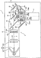
图1是表示本发明的第一实施方式的投影机的结构的模式图;FIG. 1 is a schematic diagram showing the configuration of a projector according to a first embodiment of the present invention;
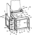
图2是表示上述实施方式的光学装置本体的立体图;2 is a perspective view showing the optical device body of the above-mentioned embodiment;
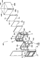
图3是表示上述实施方式的光学装置本体的结构的分解立体图;3 is an exploded perspective view showing the structure of the optical device body of the above embodiment;
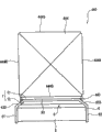
图4是表示将上述实施方式的保持构件和一对透光性基板安装在棱镜上的状态的俯视图;4 is a plan view showing a state in which the holding member and a pair of translucent substrates of the above-described embodiment are mounted on a prism;
图5是表示将上述实施方式的保持构件和一对透光性基板安装在棱镜上的状态的侧视图;5 is a side view showing a state in which the holding member and a pair of translucent substrates of the above-mentioned embodiment are mounted on a prism;
图6是表示设置在本发明的第二实施方式的投影机上的保持构件的俯视图。6 is a plan view showing a holding member provided in a projector according to a second embodiment of the present invention.
标号说明Label description
1...投影机1...Projector
5(5R、5G、5B)...液晶面板(光调制装置)5 (5R, 5G, 5B)...LCD panel (light modulation device)
6、6A...保持构件6, 6A... holding member
7...透光性基板7...Light-transmitting substrate
44...光学装置44...optical device
71...射出侧基板71...Emitting side substrate
72...入射侧基板72...Incident side substrate
416...光源灯(光源)416...Light source lamp (light source)
443...射出侧偏振板(光学元件)443...Exit side polarizing plate (optical element)
444...十字分色棱镜(棱镜)444...Cross dichroic prism (prism)
631...开口631...opening
711...上方延伸部(延伸部分)711...Upper extension (extension part)
712...下方延伸部(延伸部分)712... Lower extension (extension part)
444R、444G、444B...光束入射面444R, 444G, 444B...Beam incident surface
具体实施方式 Detailed ways
[1.第一实施方式][1. First Embodiment]
下面,基于附图说明本发明的第一实施方式。Next, a first embodiment of the present invention will be described based on the drawings.
(1)投影机1的结构(1) Structure of Projector 1
图1是表示本实施方式的投影机1的内部结构的模式图。FIG. 1 is a schematic diagram showing the internal structure of a projector 1 according to the present embodiment.
投影机1是形成与图像信息相对应的光学像,并将该光学像放大投射在屏幕等上的投影机。该投影机1,如图1所示,构成为包括:外装壳体2、投射透镜3、光学单元4等。The projector 1 is a projector that forms an optical image corresponding to image information, and enlarges and projects the optical image on a screen or the like. The projector 1 is configured to include an
另外,在图1中,虽然省略了图示,但在外装壳体2内,在投射透镜3以及光学单元4以外的空间内配置有:由冷却投影机1内部的冷却风扇等构成的冷却单元,向投影机1内部的各结构构件提供电力的电源单元,以及控制投影机1全体的控制单元等。In addition, in FIG. 1, although illustration is omitted, in the
其中,外装壳体2由合成树脂等构成,形成为在内部收纳配置投射透镜3以及光学单元4等的整体大致长方体状。虽然省略了图示,但该外装壳体2由下述两部分构成:分别构成投影机1的顶面、前面、背面以及左右两侧面的上部壳体,和分别构成投影机1的底面、前面以及背面的下部壳体;上部壳体以及下部壳体由螺丝等互相固定在一起。另外,外装壳体2不仅限于合成树脂等,也可以由其他的材料形成,例如也可以由金属等构成。Among them, the
投射透镜3具有作为将由后述的光学单元4形成的光学像(彩色图像)放大投射在未图示的屏幕上的投射光学系统的功能。该投射透镜3构成为,在筒状的镜筒内收纳有多块透镜的组透镜。The
(2)光学单元4的结构(2) Structure of the optical unit 4
光学单元4是在控制单元的控制下,对从光源射出的光束光学性地进行处理,从而形成与图像信息相对应的光学像(彩色图像)的单元。该光学单元4,具有沿着外装壳体2的背面延伸、同时沿着该外装壳体2的侧面延伸的俯视大致L字形状。The optical unit 4 is a unit for optically processing the light beam emitted from the light source under the control of the control unit to form an optical image (color image) corresponding to image information. The optical unit 4 has a substantially L-shape in plan view extending along the back surface of the
该光学单元4包括:照明光学装置41,色分离光学装置42,中继光学装置43,光学装置44,和在内部收纳配置上述元件中的光学元件41~43以及光学装置44的入射侧偏振板442的光学部件用壳体45。The optical unit 4 includes: an illumination
照明光学装置41,是用于大致均匀地照明构成光学装置44的后述的液晶面板5的图像形成区域的光学系统。该照明光学装置41构成为包括:光源装置411、第一透镜阵列412,第二透镜阵列413,偏振转换元件414和重叠透镜415。The illumination
光源装置411包括:射出放射状的光线的光源灯416,对从该光源灯416射出的放射光进行反射从而使其会聚到预定位置的反射器417,和将由反射器417会聚的光束相对于照明光轴A平行化的平行化凹透镜418。作为这样的光源灯416,可以使用卤素灯、金属卤化物灯、高压水银灯。另外,作为反射器417,可以由具有旋转椭圆面的椭圆面反射器构成,此外可以由具有旋转抛物面的抛物面反射器构成。在该情况下,能够省略平行化凹透镜418。The
第一透镜阵列412,具有小透镜排列成矩阵状的结构,所述小透镜从入射光束的光轴方向观察具有大致矩形状的轮廓。各小透镜,将从光源装置411射出的光束分割成多束部分光束。The
第二透镜阵列413,具有与第一透镜阵列412大致同样的结构,具有小透镜排列成矩阵状的结构。该第二透镜阵列413,具有与配置在该第二透镜阵列413的光路后级的重叠透镜415一同,使从第一透镜阵列412的各小透镜射出的影像成像在光学装置44的后述的液晶面板5的图像形成区域上的功能。The
偏振转换元件414,配置于第二透镜阵列413和重叠透镜415之间,将来自第二透镜阵列413的光转换成大致1种直线偏振光。The
具体地说,由偏振转换元件414转换成大致1种直线偏振光的各部分光,通过重叠透镜415最终在后述的液晶面板5的图像形成区域上大致重叠。在采用了调制偏振光的类型的液晶面板的投影机中,因为只能利用1种偏振光,所以只能利用来自发出随机性的偏振光的光源装置411的光的大致一半。因此,通过采用偏振转换元件414,将来自光源装置411的射出光转换成大致1种直线偏振光,提高光在光学装置44的利用效率。Specifically, each partial light converted into substantially one type of linearly polarized light by the
色分离光学装置42,具有2片分色镜421、422和反射镜423。具有作为通过分色镜421、422将从照明光学装置41射出的多个部分光束分离为红(R)、绿(G)、蓝(B)3种颜色的色光的色分离光学系统的功能。The color separation
中继光学装置43,具备入射侧透镜431、中继透镜433以及反射镜432、434,具有将作为由色分离光学装置42所分离的红色光导引到红色光用液晶面板5(5R)的功能。The relay
此时,在色分离光学装置42的分色镜421中,从照明光学装置41射出的光束之中的红色光成分和绿色光成分透射,同时蓝色光成分反射。由分色镜421反射的蓝色光,由反射镜423反射,并通过场透镜419到达蓝色光用的液晶面板5(5B)。该场透镜419,将从第二透镜阵列413射出的各部分光束转换成相对于其中心轴(主光线)平行的光束。设置于绿色光用、红色光用的液晶面板5(5G、5R)的光入射侧的场透镜419也是同样。At this time, in the
在透射过分色镜421的红色光和绿色光之中,绿色光由分色镜422反射,并通过场透镜419到达绿色光用的液晶面板5(5G)。另一方面,红色光透射分色镜422而通过中继光学装置43,进而通过场透镜419到达红色光用的液晶面板5(5R)。另外,之所以在红色光的光路上配置有中继光学装置43,是因为红色光的光路的长度比其他的色光的光路的长度长,为了防止因光的发散等引起的光的利用效率的降低的缘故。即,是为了将入射到入射侧透镜431的部分光束原封不动地传到场透镜419。另外,在中继光学装置43上,设成了在3种色光中使红色光通过的结构,但并不局限于此,例如,也可以设成使蓝色光通过的结构。Among the red light and green light transmitted through the
光学装置44,根据图像信息对从色分离光学装置42射出的3种色光分别进行调制,并将调制之后的各色光合成从而形成光学像(彩色图像)。The
该光学装置44构成为具备:作为光调制装置的3块液晶面板5(设红色光用的液晶面板为5R,设绿色光用的液晶面板为5G,设蓝色光用的液晶面板为5B),分别配置于这些液晶面板5的光束入射侧的3个入射侧偏振板442,分别配置于各液晶面板5的光束射出侧的3个射出侧偏振板443,作为色合成光学装置的十字分色棱镜444,保持液晶面板5的保持构件6(在图1中图示省略),和夹持射出侧偏振板443的一对透光性基板7(在图1中图示省略)。而且,其中,由液晶面板5、射出侧偏振板443、十字分色棱镜444、保持构件6以及一对透光性基板7,构成光学装置本体440。另外,对于光学装置本体440,在后面详细叙述。The
其中,用偏振转换元件414将偏振方向统一成大致相同方向的各色光入射在入射侧偏振板442上,该入射侧偏振板442,在入射的光束中,仅使与用偏振转换元件414统一的光束的偏振方向大致相同的偏振光透射,将其它的光束吸收。该入射侧偏振板442,例如具有将蓝宝石玻璃或水晶等透光性基板上粘贴有偏振膜的结构。Among them, each color light whose polarization directions are unified into approximately the same direction by the
液晶面板5,具有在一对透明的玻璃基板中密闭封入作为光学物质的液晶的结构,并根据从控制单元输入的驱动信号,来控制位于图像形成区域内的液晶的取向状态,调制从入射侧偏振板442射出的偏振光束的偏振方向,从而形成与入射的色光相对应的彩色图像。The
射出侧偏振板443,相当于本发明的光学元件,在从液晶面板5射出的光束中,仅使具有与入射侧偏振板442的光束的透射方向垂直的偏振方向的光束透射,而吸收其他光束。该射出侧偏振板443,在本实施方式中,形成为薄膜状。The output
十字分色棱镜444,是将从各射出侧偏振板443射出的作为R图像、G图像以及B图像的各色光合成而形成光学像(彩色图像)的合成光学装置。该十字分色棱镜444,形成将4个直角棱镜贴合在一起的俯视大致正方形状,并在将直角棱镜彼此贴合在一起的界面上,形成2个电介质多层膜。这些电介质多层膜,使通过了配设在与投射透镜3相对一侧(G色光侧)的射出侧偏振板443的色光透射,并反射通过了其余的2个射出侧偏振板443(R色光侧以及B色光侧)的色光。如此地,将由各入射侧偏振板442、各液晶面板5以及各射出侧偏振板443所调制的各色光合成而形成彩色图像。The cross
光学部件用壳体45是,在内部设定有预定的照明光轴A,将上述的光学部件41~44配置在相对于照明光轴A的预定位置上的合成树脂制的箱状构件。在该光学部件用壳体45的内部,虽然省略了详细的图示,但形成有用于对各光学部件41~44进行定位固定用的多个槽。The
(3)光学装置本体440的结构(3) Structure of the
图2是表示光学装置本体440的立体图。另外,图3是表示光学装置本体440的分解立体图。另外,为了使结构容易理解,在图2中,省略了液晶面板5B的图示,在图3中,仅图示配置在绿色光的光路上的各光学部件。FIG. 2 is a perspective view showing the optical device
光学装置本体440,通过液晶面板5根据图像信息调制入射的光束,从而形成与该入射光束相对应的彩色图像,并通过十字分色棱镜(以下有时简称为“棱镜”)444合成该彩色图像从而形成光学像(彩色图像)。该光学装置本体440,如上所述,包括:液晶面板5、射出侧偏振板443、棱镜444、保持构件6以及一对透光性基板7,由此构成为单元。The
下面,对在棱镜444的各光束入射面(设红色光入射的光束入射面为444R、设绿色光入射的光束入射面为444G、设蓝色光入射的光束入射面为444B)中、配置在光束入射面444G侧的各构件的配置以及结构进行说明,但对于其它的光束入射面444R、444B也设为同样的结构。Next, in each of the beam incident surfaces of the prism 444 (the beam incident surface where red light is incident is 444R, the beam incident surface where green light is incident is 444G, and the beam incident surface where blue light is incident is 444B), the light beams are arranged The arrangement and structure of each member on the
(3-1)透光性基板7的结构(3-1) Structure of the
在棱镜444中,在绿色光入射的光束入射面444G上,如图2以及图3所示,构成一对透光性基板7,并粘接固定有配置在射出侧偏振板443的光束射出侧的射出侧基板71。In the
该射出侧基板71,形成为比射出侧偏振板443的外形尺寸大,而且比光束入射面444R、444G、444B的外形尺寸大。如果详细叙述,射出侧基板71形成为,在将该射出侧基板71固定在光束入射面444G上时,向与射入该光束入射面444G的光束的光轴垂直的方向、并且是与形成了各光束入射面444R、444G、444B的方向垂直的方向即上下方向延伸。其中,向上方侧延伸的部分形成上方延伸部711,向下方侧延伸的部分形成下方延伸部712。而且,在该射出侧基板71的光束入射面71A的大致中央,粘贴有射出侧偏振板443。The exit-
在粘贴在射出侧基板71的光束入射面71A上的射出侧偏振板443的光束入射侧,设有入射侧基板72,其构成一对透光性基板7,与射出侧基板71一起夹持射出侧偏振板443。该入射侧基板72形成得比射出侧偏振板443的外形尺寸稍大,并以覆盖射出侧偏振板443的方式粘贴在该射出侧偏振板443的光束入射侧的面上。On the light beam incident side of the exit
另外,构成这一对透光性基板7的射出侧基板71以及入射侧基板72,可以由水晶、蓝宝石、YAG结晶玻璃、石英、派热克斯玻璃(パイレツクス,pyrex,注册商标)以及白板玻璃等形成。In addition, the emitting-
这样,通过由一对透光性基板7夹持射出侧偏振板443,将在射出侧偏振板443产生的热量向入射侧基板72以及射出侧基板71传递,所以能够抑制射出侧偏振板443的温度上升。In this way, by sandwiching the output-side
(3-2)液晶面板5的结构(3-2) Structure of
液晶面板5包括:在内部密闭封入了液晶元件的面板本体51,和保持该面板本体51的保持框52。The
其中,面板本体51形成为从入射光束的光轴方向观察大致矩形的箱形形状。而且,该面板本体51,如前所述,根据从控制单元输入的驱动信号,控制被封入内部的液晶元件的取向状态,在入射的光束透过的过程中对该液晶元件进行调制,从而形成与入射光束相对应的彩色图像。Among them, the panel
从射入该面板本体51的光束的光轴方向观察,在该面板本体51的四角分别形成有贯通面板本体51的孔部511。Viewed from the direction of the optical axis of the light beam incident on the
保持框52是从上方观察具有大致U字状、另外从入射光束的光轴方向观察具有大致矩形形状的金属制的构件。在该保持框52上,形成有:沿入射光束的光轴向上下方向延伸、互相相对配置的一对板状部521、522,和连接该板状部521、522的光束射出侧的端部的板状部523。The holding
其中,在一对板状部521、522的与它们互相相对的面相反一侧的面上,分别形成有向面外方向突出的3个突出部5211、5221。具体地说,突出部5211、5221分别形成在板状部521、522的外侧的面的上方、大致中央、下方附近。而且,这些突出部5211、5221分别嵌合于后述的保持构件6的开口611、621。Among them, three protruding
在板状部523的大致中央,形成有从面板本体51射出的光束透过的大致矩形形状的开口5231。该开口5231,以与面板本体51的图像形成区域、即配置有液晶元件的区域相对应的尺寸而形成。A substantially
另外,在板状部523的四角,分别形成有螺丝孔5232,在该螺栓孔5232上,螺合有贯通形成在面板本体51上的孔部511的螺纹件(图示省略)。由此,将面板本体51固定在保持框52上。In addition,
(3-3)保持构件6的结构(3-3) Structure of holding
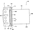
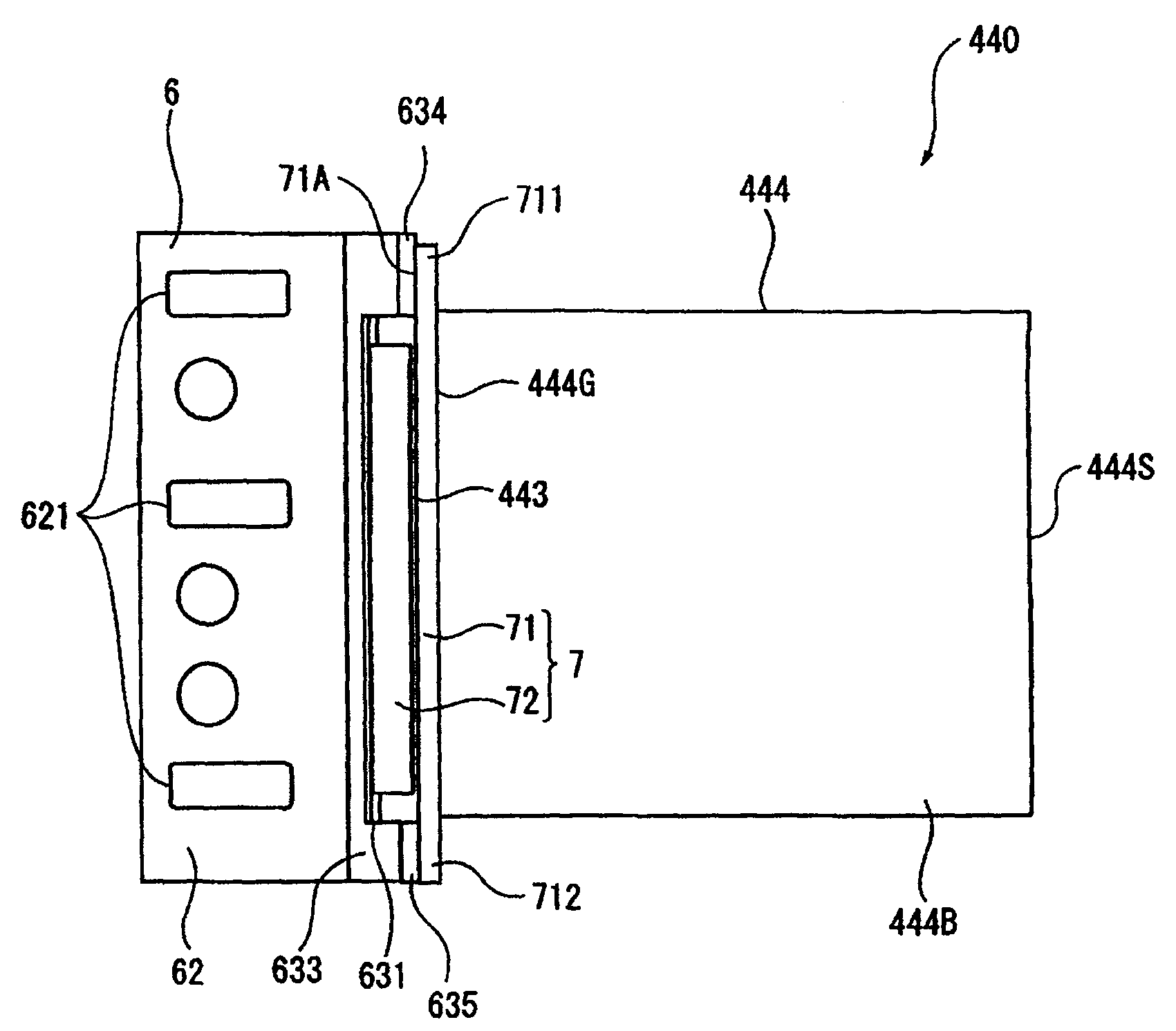
图4是从上方观察将保持构件6和一对透光性基板7安装在棱镜444上的状态的俯视图。另外,图5是表示将保持构件6和一对透光性基板7安装在棱镜444上的状态的侧视图。另外,在图5中,省略了液晶面板5(5G)的图示。FIG. 4 is a plan view of a state in which the holding
保持构件6,如前所述,是以从光束射出侧覆盖液晶面板5的方式保持液晶面板5的构件,如图2~图5所示,该保持构件6,被设置成覆盖入射侧基板72以及射出侧偏振板443,然后被粘接固定在粘贴在棱镜444的光束入射面444G上的射出侧基板71上。The holding
该保持构件6与保持框52同样,是从上方观察具有大致U字状、从入射光束的光轴方向观察具有大致矩形形状的金属制的构件。该保持构件6包括:沿入射光束的光轴向上下方向延伸、互相相对配置的一对板状部61、62,和连接该板状部61、62的光束射出侧的端部之间的板状部63。Like the holding
在一对板状部61、62上,如图2、图3以及图5所示,在与形成在保持框52上的突出部5211、5221相对应的位置上,分别形成3个横向较长的大致矩形形状的开口611、621。在该开口611、621上分别嵌合突出部5211、5221,在该状态下使液晶面板5相对于保持构件6向光轴方向偏移,由此进行液晶面板5的位置调整。另外,保持构件6的板状部61、62的互相相对的面,与液晶面板5的保持框52的外侧的面,通过紫外线固化性粘接剂等粘接固定在一起。On the pair of plate-shaped
连接一对板状部61、62的光束射出侧的端部之间的板状部63,如图4所示,形成为大致U字形状,其从板状部61、62的光束射出侧的端部互相接近,并且向光束射出侧倾斜,然后向与一对板状部61、62垂直的方向延伸并连接。As shown in FIG. The end portions are close to each other, inclined toward the light beam emission side, and then extended in a direction perpendicular to the pair of plate-
在该板状部63的大致中央,形成有从入射光束的光轴方向观察大致矩形的开口631。在该开口631上,如图2以及图4所示,入射侧基板72露出,从液晶面板5射出的光束射入在该开口631上露出的入射侧基板72。A substantially
这里,板状部61、62间的内侧的尺寸与液晶面板5的水平方向的尺寸大致相同,所以在保持构件6保持液晶面板5时,液晶面板5不位于该板状部63的板状部61、62附近的倾斜部632、633(设连接在板状部61上的倾斜部为632、设连接在板状部62上的倾斜部为633)的光束射出侧。因此,在将该保持构件6固定在射出侧基板71上时,如图4所示,在液晶面板5与入射侧基板72之间,形成有具有预定的间隔的间隙S。冷却液晶面板5的光束射出侧的面以及入射侧基板72的冷却空气在该间隙S中流通。由此,不但能够直接冷却液晶面板5,还能够对在该液晶面板5上产生、传导到保持构件6上的热量,以及在射出侧偏振板443上产生、传导到入射侧基板72上的热量进行冷却。因此,能够提高这些液晶面板5以及射出侧偏振板443的冷却效率。Here, the dimension inside between the plate-
位于板状部63的开口631的上方以及下方的水平部634、635的光束射出侧的面,如图5所示,通过紫外线固化性粘接剂等粘接固定在粘贴在棱镜444的光束入射面444R、444G、444B上的射出侧基板71的光束入射面71A上。这些水平部634、635所粘接固定的射出侧基板71的位置,被设为该射出侧基板71的从棱镜444的光束入射面444G向上下方向延伸的上方延伸部711以及下方延伸部712。The surfaces on the beam exit side of the
如果详细叙述,在板状部63中位于上方的水平部634被粘接在射出侧基板71的光束入射面71A的与上方延伸部711相对应的位置上,另外,位于下方的水平部635被粘接在光束入射面71A的与下方延伸部712相对应的位置上。由此,保持构件6被固定在射出侧基板71上。As described in detail, the upper
(3-4)各构件的固定(3-4) Fixing of each component
对上面说明的射出侧偏振板443、液晶面板5以及透光性基板7的安装在光束入射面444G上的情况进行说明。The case where the above-described exit-side
首先,在棱镜444的光束入射面444G上,配置一对透光性基板7中的射出侧基板71。此时,射出侧基板71,相对于光束入射面444R、444G、444B,以上下端部(上方延伸部711以及下方延伸部712)从该射出侧基板71所配置的光束入射面444G向上下延伸的方式粘接固定。First, on the light
然后,在射出侧基板71的光束入射面71A的大致中央部分上,粘贴射出侧偏振板443,并在该射出侧偏振板443的光束入射面上,以覆盖该射出侧偏振板443的方式,粘接固定入射侧基板72。Next, the exit-side
其次,由将保持构件6保持将面板本体51螺纹固定于保持框52的液晶面板5(5G)。此时,在保持框52的板状部521、522与保持构件6的板状部61、62之间涂施紫外线固化性粘接剂,以将该保持框52安装在保持构件6上,使得形成于保持框52的板状部521、522的外侧的面上的突出部5211、5221分别嵌合于被形成于保持构件6的板状部61、62上的开口611、621。Next, the
接下来,将保持液晶面板5的保持构件6通过紫外线固化性粘接剂等固定在射出侧基板71的光束入射面71A上,其中所述射出侧基板71是固定在棱镜444的光束入射面444G上的。从而,将保持构件6的光束射出侧的面的与水平部634相对应的部分粘接固定在射出侧基板71的光束入射面71A的与上方延伸部711相对应的位置上,另外,将与水平部635相对应的部分粘接固定在光束入射面71A的与下方延伸部712相对应的位置上。Next, the holding
然后,在进行液晶面板5的位置调整后,通过使紫外线照射在这些各构件上,将射出侧偏振板443、液晶面板5、保持构件6以及透光性基板7固定在棱镜444的光束入射面444G上。Then, after adjusting the position of the
根据以上那样的本实施方式的投影机1,可以起到以下的效果。According to the projector 1 of the present embodiment as described above, the following effects can be obtained.
即,保持液晶面板5G的保持构件6,被粘接固定在射出侧基板71的光束入射面71A上,其中所述射出侧基板71是粘接固定在棱镜444的光束入射面444G上的。由此,从液晶面板5G侧观察,能够减少夹在与棱镜444之间的粘接层。That is, the holding
如果详细叙述,在将保持构件6粘接固定在与射出侧基板71一同夹持射出侧偏振板443的入射侧基板72上时,在棱镜444与射出侧基板71之间、射出侧基板71与射出侧偏振板443之间、射出侧偏振板443与入射侧基板72之间、以及入射侧基板72与保持构件6之间存在合计四层粘接层。与此相对,由于将保持构件6粘接固定在射出侧基板71上,所以可以设为在棱镜444与射出侧基板71之间以及射出侧基板71与保持构件6之间合计两层。由此可减少夹置的粘接层的数目。由此,能够使由粘接层的经年变化引起的液晶面板5G的位置偏移难以产生,能够实现光学装置44的长寿命化。另外,能够容易地进行该液晶面板5G的位置调整。另外,这样的效果,在液晶面板5R、5B中也同样能够有效。As described in detail, when the holding
另外,由于保持构件6被粘接固定在射出侧基板71的光束入射面71A上,所以除了能够容易地进行保持构件6的安装,还能够简单地进行由该保持构件6保持的液晶面板5的位置调整。In addition, since the holding
进而,由于不需要另外设置用于保持射出侧偏振板443以及夹持该射出侧偏振板443的一对透光性基板7的构件,所以能够使光学装置本体440的结构简单化,进而能够使投影机1的制造工序简单化。另外,由于这样一来结构构件变少,所以能够使投影机1的分解(拆卸)等工序简单化,能够提高产品的循环再利用性。Furthermore, since there is no need to additionally provide members for holding the exit-side
另外,在将保持构件6安装在射出侧基板71上时,该保持构件6的水平部634、635的光束射出侧的面,粘接在射出侧基板71的光束入射面71A的与上方延伸部711以及下方延伸部712相对应的位置上。由此,能够实现射出侧偏振板443的大型化以及棱镜444的小型化。In addition, when the holding
如果详细叙述,在射出侧基板71中,在与棱镜444的光束入射面444R、444G、444B相对应的区域内,不必确保用于安装保持构件6的区域,所以能够增大粘贴在该射出侧基板71的光束入射面71A上的射出侧偏振板443。由此,能够配置具有比液晶面板5的图像形成区域更大的尺寸的射出侧偏振板443,所以能够使从该液晶面板5射出的光束可靠地射入射出侧偏振板443。If described in detail, in the emission-
另一方面,当在射出侧基板71的与光束入射面444R、444G、444B相对应的区域内具有保持构件6的粘接区域时,只要不改变射出侧偏振板443的尺寸,为了确保射出侧基板71上的保持构件6的粘接区域,必需增大棱镜444的光束入射面444R、444G、444B。与此相对,通过在射出侧基板71中在与从光束入射面444R、444G、444B向上下延伸的上方延伸部711以及下方延伸部712相对应的光束入射面71A上,粘接固定保持构件6,能够减小棱镜444的光束入射面444R、444G、444B。因此,能够实现棱镜444的小型化。On the other hand, when there is an adhesive region of the holding
另外,射出侧基板71上的保持构件6的粘接区域,设为作为从棱镜444的光束入射面444R、444G、444B向上方延伸的部分的上方延伸部711,以及向下方延伸的下方延伸部712。由此,例如光束入射面444R、444B位于棱镜444的光束入射面444G的水平方向,所以在射出侧基板71向水平方向延伸时,与固定粘接在其他的光束入射面上的射出侧基板71相干涉。与此相对,由于射出侧基板71的延伸方向是上下方向,所以没有这样的干涉,能够在各个光束入射面444R、444G、444B上配置射出侧基板71。因此,能够在各个光束入射面444R、444G、444B上适当地配置射出侧基板71以及保持构件6。另外,由此,能够在所有的液晶面板5(5R、5G、5B)以及保持构件6中起到前述的液晶面板5的位置偏移的抑制以及保持构件6的固定容易等效果。In addition, the bonding region of the holding
进而,通过在保持构件6的板状部63上形成倾斜部632、633,能够在保持在该保持构件6上的液晶面板5与从形成在板状部63上的开口631露出的入射侧基板72之间形成间隙S,能够使冷却空气在该间隙S中流通。由此,不但能够直接冷却液晶面板5的光束射出面,还能够冷却该液晶面板5的热量传导的保持构件6、以及射出侧偏振板443的热量传导的入射侧基板72。因此,能够高效冷却这些液晶面板5以及射出侧偏振板443。Furthermore, by forming the
[2.第二实施方式][2. Second Embodiment]
接下来,对本发明的第二实施方式的投影机进行说明。Next, a projector according to a second embodiment of the present invention will be described.
本实施方式的投影机,具有与第一实施方式所示的投影机1相同的结构,但保持液晶面板5的保持构件的形状与投影机1不同。另外,在以下的说明中,对于与已经说明的部分相同或大致相同的部分,标以相同的标号并将说明省略。The projector of this embodiment has the same structure as the projector 1 shown in the first embodiment, but the shape of the holding member holding the
本实施方式的投影机,虽然省略了详细的图示,但与前述的投影机1相同,除了光学单元4,还包括冷却单元、电源单元和控制单元等,以及在内部收纳这些单元的外装壳体2。Although detailed illustrations are omitted, the projector of this embodiment includes, in addition to the optical unit 4 , a cooling unit, a power supply unit, a control unit, and the like, as well as an exterior case that accommodates these units, similarly to the projector 1 described above.
其中,光学单元4是根据图像信息对从光源射出的光束进行调制,从而形成光学像并将其投射的单元,包括:照明光学装置41,色分离光学装置42,中继光学装置43,光学装置44,光学部件用壳体45和投射透镜46。其中,光学装置44,代替光学装置本体440,具备光学装置本体440A。Among them, the optical unit 4 is a unit that modulates the light beam emitted from the light source according to the image information, thereby forming an optical image and projecting it, including: an illumination
图6是表示本实施方式的光学装置本体440A的俯视图。另外,在图6中,省略了配置在棱镜444的光束入射面444R、444B侧的各构件的图示。FIG. 6 is a plan view showing an optical device
光学装置本体440A,如图6所示,包括:棱镜444,粘接固定在该棱镜444中绿色光入射的光束入射面444G上的射出侧基板71,粘贴在该射出侧基板71上的射出侧偏振板443,以覆盖射出侧偏振板443的方式固定的入射侧基板72,液晶面板5(5G),和保持该液晶面板5(5G)、并粘接固定在射出侧基板71上的保持构件6A。The
另外,在图6中省略了图示,但在棱镜444的光束入射面444R、444G,也设为同样的结构。另外,在本实施方式中,射出侧基板71,形成为与棱镜444的光束入射面444R、444G、444B的各自大致相同的大小,并与该光束入射面444R、444G、444B重合地粘接固定。In addition, although illustration is omitted in FIG. 6 , the beam incident surfaces 444R and 444G of the
保持构件6A,形成为从上方观察大致H字状,另外,形成为从射入该保持构件6A所保持的液晶面板5的光束的光轴方向观察大致矩形形状。该保持构件6A,被设置成覆盖入射侧基板72以及射出侧偏振板443,粘接固定在射出侧基板71的光束入射面71A上。在该保持构件6A上,形成有:沿着射入液晶面板5的光束的光轴、同时向上下延伸、互相相对配置的一对板状部6A1、6A2,和将该板状部6A1、6A2的沿着入射光束的光轴的方向的大致中央部分之间桥接的板状部6A3。The holding
其中,在从一对板状部6A1、6A2的光束入射侧的端部到板状部6A3的范围内,虽然省略详细的图示,但在上方、大致中央、下方分别形成了具有与形成在前述的保持构件6上的开口611、621同样的横向较长的大致矩形形状的开口。在这些开口上,嵌合有形成在液晶面板5上的突出部5211、5221(参照图3)。另外,在板状部6A1、6A2的互相相对的面上,涂布有紫外线固化性粘接剂,通过该粘接剂,液晶面板5在位置调整后,固定在保持构件6A上。Among them, in the range from the beam-incident-side end of the pair of plate-shaped parts 6A1 and 6A2 to the plate-shaped part 6A3, although detailed illustration is omitted, there are respectively formed on the upper side, the approximate center, and the lower side. The
在板状部6A3上,虽然省略详细的图示,但在大致中央形成有大致矩形形状的开口。该开口,在保持构件6A保持液晶面板5时,与该液晶面板5的图像形成区域的尺寸相对应地形成在与该图像形成区域相对应的位置上。经由该开口,从液晶面板5射出的光束射入入射侧基板72,该光束经由入射侧基板72射入射出侧偏振板443。In the plate-like portion 6A3 , although detailed illustration is omitted, an opening having a substantially rectangular shape is formed substantially at the center. This opening is formed at a position corresponding to the image forming area corresponding to the size of the image forming area of the
这里,一对板状部6A1、6A2的光束射出侧的端面6A11、6A21,设为粘接固定在射出侧基板71的光束入射面71A上的粘接面,其中所述射出侧基板71是固定在棱镜444的光束入射面444G上的。即,在这些端面6A11、6A21上,涂布有紫外线固化性的粘接剂,该端面6A11、6A21,被粘接在射出侧基板71的光束入射面71A的水平方向的端部附近。由此,能够将保持构件6A固定在射出侧基板71上。Here, the end faces 6A11, 6A21 of the pair of plate-shaped parts 6A1, 6A2 on the beam emitting side are set as bonding surfaces that are bonded and fixed to the
这里,在板状部6A1、6A2中,从板状部6A3的光束射出侧的面到作为板状部6A1、6A2的端部的面的端面6A11、6A21的尺寸,形成为比从射出侧基板71的光束入射面71A到入射侧基板72的光束入射面的尺寸大。因此,在板状部6A3的光束射出侧的面与入射侧基板72的光束入射面之间,形成了有具有预定的间隔的间隙SA。与前述的保持构件6的情况相同,冷却空气在该间隙SA中流通,直接冷却液晶面板5的光束射出面,同时对在该液晶面板5上产生、传导到保持构件6A上的热量,以及在射出侧偏振板443上产生、传导到入射侧基板72上的热量进行冷却。Here, in the plate-shaped parts 6A1 and 6A2, the dimensions from the surface of the plate-shaped part 6A3 on the beam-emitting side to the end surfaces 6A11 and 6A21 which are the faces of the ends of the plate-shaped parts 6A1 and 6A2 are formed to be larger than those from the surface of the plate-shaped part 6A1 and 6A2. The size from the
根据以上那样的本实施方式的投影机,可以起到与前述的投影机1同样的效果。According to the projector of the present embodiment as described above, the same effects as those of the projector 1 described above can be achieved.
即,保持液晶面板5的保持构件6A,被粘接固定在射出侧基板71的光束入射面71A上,其中所述射出侧基板71是粘接固定在棱镜444的光束入射面444R、444G、444B上的。由此,与将该保持构件6A固定在入射侧基板72上的情况相比,能够减少夹在从液晶面板5到棱镜444之间的粘接层。因此,能够使液晶面板5G的位置偏移难以产生。因此,能够使液晶面板5G的光轴偏移难以产生。That is, the holding
由于保持构件6A被粘接固定在射出侧基板71上,所以能够容易地进行该保持构件6A的安装。另外,在进行保持构件6A、一对透光性基板7以及射出侧偏振板443的固定时,不需要设置其他的构件,所以能够使光学装置本体440A、进而使投影机的结构简单化。由此,能够使投影机的制造工序以及分解工序简单化,能够提高产品的循环再利用性。Since the holding
进而,由于能够在保持构件6A的板状部6A3与入射侧基板72之间形成间隙SA,所以能够使冷却空气在该间隙SA中流通。因此,能够冷却液晶面板5、保持构件6A以及入射侧基板72,所以能够提高保持在保持构件6A上的液晶面板5以及射出侧偏振板443的冷却效率。Furthermore, since the gap SA can be formed between the plate-shaped portion 6A3 of the holding
[3.实施方式的变形][3. Modification of Embodiment]
用于实施本发明的最佳的结构等,在上面的叙述中公开,但本发明并不限定于此。即,在上面所公开的对形状、材质等进行限定的叙述,是为了使本发明的理解更加容易而例示性地进行的叙述,并不是限定本发明,使用除去了上述形状、材质等限定的部分或全部限定的构件名称进行的叙述,也包括在本发明内。The best structure and the like for carrying out the present invention are disclosed in the above description, but the present invention is not limited thereto. That is, the above-disclosed descriptions that limit the shape, material, etc. are illustrative descriptions to facilitate the understanding of the present invention, and do not limit the present invention. The descriptions made by partially or fully qualified component names are also included in the present invention.
在上述各实施方式中,设为将保持构件6、6A粘接固定在射出侧基板71的光束入射面71A上,但本发明并不限定于此。例如,可以设为将保持构件6、6A固定在射出侧基板71的光束射出侧的面上的结构,另外也可以设为将保持构件6、6A固定在侧面上的结构,其中所述侧面是连接射出侧基板71的光束入射面71A与光束射出侧的面的。In each of the above-described embodiments, the holding
在上述各实施方式中,各液晶面板5(5R、5G、5B)分别由保持构件6、6A所保持,该各保持构件6、6A粘接固定在射出侧基板71上,其中所述射出侧基板71是固定在棱镜444的光束入射面444R、444G、444B上的,但本发明并不限定于此,在各液晶面板5(5R、5G、5B)中,只要至少一个液晶面板5由保持构件6、6A所保持,并被固定在射出侧基板71上即可。In each of the above-mentioned embodiments, each liquid crystal panel 5 (5R, 5G, 5B) is held by holding
在上述第一实施方式中,射出侧基板71被形成为在上下方向上比棱镜444的光束入射面444R、444G、444B大,该射出侧基板71以从各光束入射面444R、444G、444B向上下方向延伸的方式而被固定,但本发明并不限定于此。例如,也可以形成为具有与各光束入射面444R、444G、444B大致相同的尺寸。在这样的情况下,只要避开射出侧偏振板443以及入射侧基板72,将保持构件6固定在射出侧基板71上即可。In the above-mentioned first embodiment, the emission-
另外,在上述第一实施方式中,射出侧基板71具有相对于棱镜444的光束入射面444R、444G、444B向上方延伸的上方延伸部711,以及向下方延伸的下方延伸部712,但本发明并不限定于此。例如,也可以以相对于棱镜444的光束入射面向水平方向延伸的方式配置射出侧基板71。In addition, in the above-mentioned first embodiment, the output-
在上述第二实施方式中,保持构件6A的端面6A11、6A21,设为粘接在射出侧基板71的光束入射面71A的水平方向的端部附近,但本发明并不限定于此,也可以设为粘接在上下方向(高度方向)的端部附近。即,也可以设为下述结构:板状部6A1、6A2沿水平方向延伸,该板状部6A1、6A2的光束射出侧的端面6A11、6A21分别粘接在射出侧基板71的光束入射面71A的上下方向的端部附近。In the above-mentioned second embodiment, the end faces 6A11 and 6A21 of the holding
在上述第二实施方式中,保持构件6A设为,通过构成该保持构件6A的板状部6A1、6A2的光束射出侧的端面6A11、6A21,粘接在射出侧基板71的光束入射面71A上,但本发明并不限定于此。例如,可以通过从板状部的光束射出侧的面向面外方向突出的突出部,将保持构件固定在射出侧基板71上,其中所述板状部连接相对的一对板状构件间。另外,在这样的情况下,突出部可以分别形成在该突出部所形成的板状部的四角,另外也可以分别形成在构成该板状部的各边的大致中央。In the second embodiment described above, the holding
在上述各实施方式中,在入射侧基板72的光束入射面与液晶面板5之间形成了间隙S、SA,但本发明并不限定于此,也可以将这些入射侧基板72和液晶面板5配置成互相接触。In each of the above-mentioned embodiments, the gaps S and SA are formed between the light beam incident surface of the incident-
在上述各实施方式中,作为光学元件,例示了射出侧偏振板443,但本发明并不限定于此,例如,也可以使用控制光学像的视场角的视场角控制滤光片、使预定波长的色光透过的彩色滤光片等。In each of the above-described embodiments, the output-side
另外,在上述各实施方式中,设成了由一对透光性基板7夹持作为光学元件的射出侧偏振板443的结构,但本发明并不限定于此,也可以在入射侧基板72的光束入射侧配置另外的光学元件。In addition, in each of the above-mentioned embodiments, the structure in which the output-side
在上述各实施方式中,投影机1包括3个液晶面板5R、5G、5B,但本发明并不限定于此。即,在使用了2个以下或4个以上的液晶面板的投影机中,也可以应用本发明。In each of the above-described embodiments, the projector 1 includes the three
另外,在上述各实施方式中,对光学单元4具有平面看(俯视)大致L字形状的结构进行了说明,但并不限定于此,例如,也可以采用具有平面看大致U字形状的结构。In addition, in each of the above-mentioned embodiments, the optical unit 4 has been described as having a substantially L-shape in plan view (planar view), but is not limited thereto. For example, a structure having a substantially U-shape in plan view may also be employed. .
进而,在上述各实施方式中,使用了光束入射面与光束射出面不同的透过型的液晶面板5,但也可以使用光束入射面与光束射出面相同的反射型的液晶面板。Furthermore, in each of the above-described embodiments, a transmissive
在上述各实施方式中,例示了具备液晶面板5作为光调制装置的投影机1,但只要是根据图像信息调制入射光束从而形成光学像的光调制装置,也可以采用其他的结构的光调制装置。In each of the above-mentioned embodiments, the projector 1 including the
另外,在上述各实施方式中,仅例示了从观察屏幕的方向进行图像投射的正投类型的投影机1,但本发明也可以应用在从与观察屏幕的方向相反一侧进行图像投射的背投类型的投影机。In addition, in each of the above-mentioned embodiments, only the front projection type projector 1 that projects images from the direction of viewing the screen is exemplified. cast type projector.
本发明能够应用于光学装置,特别能够应用于投影机中所采用的光学装置。The present invention can be applied to optical devices, in particular to optical devices employed in projectors.
Claims (4)
Applications Claiming Priority (2)
| Application Number | Priority Date | Filing Date | Title |
|---|---|---|---|
| JP059502/2006 | 2006-03-06 | ||
| JP2006059502A JP4661635B2 (en) | 2006-03-06 | 2006-03-06 | Optical apparatus and projector |
Publications (2)
| Publication Number | Publication Date |
|---|---|
| CN101034249A CN101034249A (en) | 2007-09-12 |
| CN100555067C true CN100555067C (en) | 2009-10-28 |
Family
ID=38471143
Family Applications (1)
| Application Number | Title | Priority Date | Filing Date |
|---|---|---|---|
| CNB2007100861918A Expired - Fee Related CN100555067C (en) | 2006-03-06 | 2007-03-06 | Optical devices and projector |
Country Status (3)
| Country | Link |
|---|---|
| US (1) | US7775667B2 (en) |
| JP (1) | JP4661635B2 (en) |
| CN (1) | CN100555067C (en) |
Families Citing this family (5)
| Publication number | Priority date | Publication date | Assignee | Title |
|---|---|---|---|---|
| JP4442687B2 (en) | 2007-12-12 | 2010-03-31 | セイコーエプソン株式会社 | projector |
| US8147070B2 (en) * | 2007-12-20 | 2012-04-03 | Seiko Epson Corporation | Projector |
| JP6003365B2 (en) * | 2012-08-06 | 2016-10-05 | セイコーエプソン株式会社 | Optical device, projector, and method of manufacturing optical device |
| CN112015039A (en) * | 2019-05-29 | 2020-12-01 | 深圳光峰科技股份有限公司 | Prism components and projection equipment |
| JP2023114911A (en) * | 2022-02-07 | 2023-08-18 | セイコーエプソン株式会社 | projector |
Family Cites Families (10)
| Publication number | Priority date | Publication date | Assignee | Title |
|---|---|---|---|---|
| JP3608417B2 (en) * | 1999-02-02 | 2005-01-12 | セイコーエプソン株式会社 | Electro-optical device mounting unit and projection display device using the same |
| JP2002229121A (en) * | 2001-02-02 | 2002-08-14 | Seiko Epson Corp | projector |
| JP4042474B2 (en) * | 2001-08-08 | 2008-02-06 | セイコーエプソン株式会社 | Optical device and projector |
| JP2003066404A (en) * | 2001-08-27 | 2003-03-05 | Sony Corp | LCD projector |
| JP4079048B2 (en) * | 2002-08-27 | 2008-04-23 | セイコーエプソン株式会社 | Optical device and projector |
| JP2004198596A (en) * | 2002-12-17 | 2004-07-15 | Seiko Epson Corp | Polarizing plate and projector |
| US7148945B2 (en) * | 2003-03-14 | 2006-12-12 | Seiko Epson Corporation | Optical device having a plurality of optical modulator units, projector equipping the same, and particular heat insulation |
| US7073911B2 (en) * | 2003-03-14 | 2006-07-11 | Seiko Epson Corporation | Projector with improved heat radiation |
| JP2004333685A (en) | 2003-05-02 | 2004-11-25 | Canon Inc | Image display device |
| JP2004354587A (en) * | 2003-05-28 | 2004-12-16 | Seiko Epson Corp | Fixing plate, optical device and projector |
-
2006
- 2006-03-06 JP JP2006059502A patent/JP4661635B2/en not_active Expired - Fee Related
-
2007
- 2007-02-05 US US11/702,332 patent/US7775667B2/en not_active Expired - Fee Related
- 2007-03-06 CN CNB2007100861918A patent/CN100555067C/en not_active Expired - Fee Related
Also Published As
| Publication number | Publication date |
|---|---|
| JP4661635B2 (en) | 2011-03-30 |
| CN101034249A (en) | 2007-09-12 |
| US20070206157A1 (en) | 2007-09-06 |
| US7775667B2 (en) | 2010-08-17 |
| JP2007240604A (en) | 2007-09-20 |
Similar Documents
| Publication | Publication Date | Title |
|---|---|---|
| JP4017008B2 (en) | Optical device and projector | |
| CN101614945B (en) | Optical device and projector | |
| US7564505B2 (en) | Optical device and projector equipped with the same | |
| CN101398599A (en) | Optical device and projector | |
| CN101046608A (en) | Electro-optic device fitting structure and projection type display device | |
| JP6733378B2 (en) | Optical device and projector | |
| CN100555067C (en) | Optical devices and projector | |
| JP2002139795A (en) | projector | |
| CN100458555C (en) | Optical unit and projection type image display device using the same | |
| CN100504587C (en) | Projector | |
| JP2009036819A (en) | Optical device and projector | |
| JP2009210779A (en) | Optical device and projector | |
| CN100523992C (en) | Optical device and projector | |
| JP2011150159A (en) | Projector | |
| JP4962601B2 (en) | Optical apparatus and projector | |
| JP2009271467A (en) | Electronic equipment | |
| JP3367491B2 (en) | Electro-optical device attachment unit and projector using the same | |
| JP5141165B2 (en) | Optical apparatus and projector | |
| CN101271263A (en) | Optical device and projector | |
| JP5413499B2 (en) | Optical apparatus and projector | |
| JP2007226030A (en) | Optical component holding member and projector | |
| JP2009151170A (en) | Optical device and projector | |
| JP2018017961A (en) | projector | |
| JP4595441B2 (en) | projector | |
| JP2006053430A (en) | projector |
Legal Events
| Date | Code | Title | Description |
|---|---|---|---|
| C06 | Publication | ||
| PB01 | Publication | ||
| C10 | Entry into substantive examination | ||
| SE01 | Entry into force of request for substantive examination | ||
| C14 | Grant of patent or utility model | ||
| GR01 | Patent grant | ||
| CF01 | Termination of patent right due to non-payment of annual fee | ||
| CF01 | Termination of patent right due to non-payment of annual fee |
Granted publication date: 20091028 Termination date: 20210306 |