CN100503112C - Method for removing burrs, bevel gear cutting machine used therefor - Google Patents
Method for removing burrs, bevel gear cutting machine used therefor Download PDFInfo
- Publication number
- CN100503112C CN100503112C CNB2005100712844A CN200510071284A CN100503112C CN 100503112 C CN100503112 C CN 100503112C CN B2005100712844 A CNB2005100712844 A CN B2005100712844A CN 200510071284 A CN200510071284 A CN 200510071284A CN 100503112 C CN100503112 C CN 100503112C
- Authority
- CN
- China
- Prior art keywords
- deburring
- blade
- bevel gear
- cutting machine
- blade head
- Prior art date
- Legal status (The legal status is an assumption and is not a legal conclusion. Google has not performed a legal analysis and makes no representation as to the accuracy of the status listed.)
- Expired - Fee Related
Links
Images


Classifications
-
- B—PERFORMING OPERATIONS; TRANSPORTING
- B23—MACHINE TOOLS; METAL-WORKING NOT OTHERWISE PROVIDED FOR
- B23F—MAKING GEARS OR TOOTHED RACKS
- B23F19/00—Finishing gear teeth by other tools than those used for manufacturing gear teeth
- B23F19/10—Chamfering the end edges of gear teeth
-
- B—PERFORMING OPERATIONS; TRANSPORTING
- B23—MACHINE TOOLS; METAL-WORKING NOT OTHERWISE PROVIDED FOR
- B23Q—DETAILS, COMPONENTS, OR ACCESSORIES FOR MACHINE TOOLS, e.g. ARRANGEMENTS FOR COPYING OR CONTROLLING; MACHINE TOOLS IN GENERAL CHARACTERISED BY THE CONSTRUCTION OF PARTICULAR DETAILS OR COMPONENTS; COMBINATIONS OR ASSOCIATIONS OF METAL-WORKING MACHINES, NOT DIRECTED TO A PARTICULAR RESULT
- B23Q1/00—Members which are comprised in the general build-up of a form of machine, particularly relatively large fixed members
- B23Q1/25—Movable or adjustable work or tool supports
- B23Q1/44—Movable or adjustable work or tool supports using particular mechanisms
- B23Q1/48—Movable or adjustable work or tool supports using particular mechanisms with sliding pairs and rotating pairs
- B23Q1/4852—Movable or adjustable work or tool supports using particular mechanisms with sliding pairs and rotating pairs a single sliding pair followed perpendicularly by a single rotating pair
-
- B—PERFORMING OPERATIONS; TRANSPORTING
- B23—MACHINE TOOLS; METAL-WORKING NOT OTHERWISE PROVIDED FOR
- B23F—MAKING GEARS OR TOOTHED RACKS
- B23F19/00—Finishing gear teeth by other tools than those used for manufacturing gear teeth
- B23F19/10—Chamfering the end edges of gear teeth
- B23F19/102—Chamfering the end edges of gear teeth by milling
-
- B—PERFORMING OPERATIONS; TRANSPORTING
- B23—MACHINE TOOLS; METAL-WORKING NOT OTHERWISE PROVIDED FOR
- B23F—MAKING GEARS OR TOOTHED RACKS
- B23F5/00—Making straight gear teeth involving moving a tool relatively to a workpiece with a rolling-off or an enveloping motion with respect to the gear teeth to be made
- B23F5/20—Making straight gear teeth involving moving a tool relatively to a workpiece with a rolling-off or an enveloping motion with respect to the gear teeth to be made by milling
- B23F5/24—Making straight gear teeth involving moving a tool relatively to a workpiece with a rolling-off or an enveloping motion with respect to the gear teeth to be made by milling the tool being a hob for making bevel gears
-
- B—PERFORMING OPERATIONS; TRANSPORTING
- B23—MACHINE TOOLS; METAL-WORKING NOT OTHERWISE PROVIDED FOR
- B23Q—DETAILS, COMPONENTS, OR ACCESSORIES FOR MACHINE TOOLS, e.g. ARRANGEMENTS FOR COPYING OR CONTROLLING; MACHINE TOOLS IN GENERAL CHARACTERISED BY THE CONSTRUCTION OF PARTICULAR DETAILS OR COMPONENTS; COMBINATIONS OR ASSOCIATIONS OF METAL-WORKING MACHINES, NOT DIRECTED TO A PARTICULAR RESULT
- B23Q1/00—Members which are comprised in the general build-up of a form of machine, particularly relatively large fixed members
- B23Q1/25—Movable or adjustable work or tool supports
- B23Q1/44—Movable or adjustable work or tool supports using particular mechanisms
- B23Q1/56—Movable or adjustable work or tool supports using particular mechanisms with sliding pairs only, the sliding pairs being the first two elements of the mechanism
- B23Q1/60—Movable or adjustable work or tool supports using particular mechanisms with sliding pairs only, the sliding pairs being the first two elements of the mechanism two sliding pairs only, the sliding pairs being the first two elements of the mechanism
- B23Q1/62—Movable or adjustable work or tool supports using particular mechanisms with sliding pairs only, the sliding pairs being the first two elements of the mechanism two sliding pairs only, the sliding pairs being the first two elements of the mechanism with perpendicular axes, e.g. cross-slides
- B23Q1/621—Movable or adjustable work or tool supports using particular mechanisms with sliding pairs only, the sliding pairs being the first two elements of the mechanism two sliding pairs only, the sliding pairs being the first two elements of the mechanism with perpendicular axes, e.g. cross-slides a single sliding pair followed perpendicularly by a single sliding pair
-
- Y—GENERAL TAGGING OF NEW TECHNOLOGICAL DEVELOPMENTS; GENERAL TAGGING OF CROSS-SECTIONAL TECHNOLOGIES SPANNING OVER SEVERAL SECTIONS OF THE IPC; TECHNICAL SUBJECTS COVERED BY FORMER USPC CROSS-REFERENCE ART COLLECTIONS [XRACs] AND DIGESTS
- Y10—TECHNICAL SUBJECTS COVERED BY FORMER USPC
- Y10T—TECHNICAL SUBJECTS COVERED BY FORMER US CLASSIFICATION
- Y10T407/00—Cutters, for shaping
- Y10T407/17—Gear cutting tool
- Y10T407/1745—Rotary, tooth form cutting tool
-
- Y—GENERAL TAGGING OF NEW TECHNOLOGICAL DEVELOPMENTS; GENERAL TAGGING OF CROSS-SECTIONAL TECHNOLOGIES SPANNING OVER SEVERAL SECTIONS OF THE IPC; TECHNICAL SUBJECTS COVERED BY FORMER USPC CROSS-REFERENCE ART COLLECTIONS [XRACs] AND DIGESTS
- Y10—TECHNICAL SUBJECTS COVERED BY FORMER USPC
- Y10T—TECHNICAL SUBJECTS COVERED BY FORMER US CLASSIFICATION
- Y10T409/00—Gear cutting, milling, or planing
- Y10T409/10—Gear cutting
- Y10T409/101113—Gear chamfering or deburring
-
- Y—GENERAL TAGGING OF NEW TECHNOLOGICAL DEVELOPMENTS; GENERAL TAGGING OF CROSS-SECTIONAL TECHNOLOGIES SPANNING OVER SEVERAL SECTIONS OF THE IPC; TECHNICAL SUBJECTS COVERED BY FORMER USPC CROSS-REFERENCE ART COLLECTIONS [XRACs] AND DIGESTS
- Y10—TECHNICAL SUBJECTS COVERED BY FORMER USPC
- Y10T—TECHNICAL SUBJECTS COVERED BY FORMER US CLASSIFICATION
- Y10T409/00—Gear cutting, milling, or planing
- Y10T409/10—Gear cutting
- Y10T409/101431—Gear tooth shape generating
- Y10T409/103816—Milling with radial faced tool
- Y10T409/103975—Process
-
- Y—GENERAL TAGGING OF NEW TECHNOLOGICAL DEVELOPMENTS; GENERAL TAGGING OF CROSS-SECTIONAL TECHNOLOGIES SPANNING OVER SEVERAL SECTIONS OF THE IPC; TECHNICAL SUBJECTS COVERED BY FORMER USPC CROSS-REFERENCE ART COLLECTIONS [XRACs] AND DIGESTS
- Y10—TECHNICAL SUBJECTS COVERED BY FORMER USPC
- Y10T—TECHNICAL SUBJECTS COVERED BY FORMER US CLASSIFICATION
- Y10T409/00—Gear cutting, milling, or planing
- Y10T409/10—Gear cutting
- Y10T409/101431—Gear tooth shape generating
- Y10T409/103816—Milling with radial faced tool
- Y10T409/104134—Adapted to cut bevel gear
- Y10T409/104293—Adapted to cut bevel gear with means to continuously rotate work and means to co-form all teeth of gear
-
- Y—GENERAL TAGGING OF NEW TECHNOLOGICAL DEVELOPMENTS; GENERAL TAGGING OF CROSS-SECTIONAL TECHNOLOGIES SPANNING OVER SEVERAL SECTIONS OF THE IPC; TECHNICAL SUBJECTS COVERED BY FORMER USPC CROSS-REFERENCE ART COLLECTIONS [XRACs] AND DIGESTS
- Y10—TECHNICAL SUBJECTS COVERED BY FORMER USPC
- Y10T—TECHNICAL SUBJECTS COVERED BY FORMER US CLASSIFICATION
- Y10T409/00—Gear cutting, milling, or planing
- Y10T409/10—Gear cutting
- Y10T409/101431—Gear tooth shape generating
- Y10T409/105883—Using rotary cutter
- Y10T409/106042—Using rotary cutter having axially directed cutting edge
-
- Y—GENERAL TAGGING OF NEW TECHNOLOGICAL DEVELOPMENTS; GENERAL TAGGING OF CROSS-SECTIONAL TECHNOLOGIES SPANNING OVER SEVERAL SECTIONS OF THE IPC; TECHNICAL SUBJECTS COVERED BY FORMER USPC CROSS-REFERENCE ART COLLECTIONS [XRACs] AND DIGESTS
- Y10—TECHNICAL SUBJECTS COVERED BY FORMER USPC
- Y10T—TECHNICAL SUBJECTS COVERED BY FORMER US CLASSIFICATION
- Y10T409/00—Gear cutting, milling, or planing
- Y10T409/10—Gear cutting
- Y10T409/107791—Using rotary cutter
- Y10T409/10795—Process
-
- Y—GENERAL TAGGING OF NEW TECHNOLOGICAL DEVELOPMENTS; GENERAL TAGGING OF CROSS-SECTIONAL TECHNOLOGIES SPANNING OVER SEVERAL SECTIONS OF THE IPC; TECHNICAL SUBJECTS COVERED BY FORMER USPC CROSS-REFERENCE ART COLLECTIONS [XRACs] AND DIGESTS
- Y10—TECHNICAL SUBJECTS COVERED BY FORMER USPC
- Y10T—TECHNICAL SUBJECTS COVERED BY FORMER US CLASSIFICATION
- Y10T409/00—Gear cutting, milling, or planing
- Y10T409/10—Gear cutting
- Y10T409/107791—Using rotary cutter
- Y10T409/108745—Cutting action along work axis
- Y10T409/108904—Cutting action intersecting work axis
Landscapes
- Engineering & Computer Science (AREA)
- Mechanical Engineering (AREA)
- Gear Processing (AREA)
Abstract
Description
技术领域 technical field
本发明涉及切齿机,以及在连续程序中对锥形齿的齿边缘进行毛刺清理和/或倒角。The invention relates to gear cutting machines and to the deburring and/or chamfering of the tooth edges of conical gears in a continuous process.
背景技术 Background technique
当制造锥齿轮时,由于切削加工在外齿端处出现毛刺,具体来说,主要地位于凹陷的齿腹上,因为该齿腹相对于锥齿轮的后齿面形成一相对尖的锐角。如果工人仅在该点处去除毛刺,则一非常锋利外形的边缘仍将存在。因为有很大的伤害危险,但当锥齿轮淬硬时还因为完全硬化的危险,所以,这些边缘通常通过倒角来予以破除。如果该角度不是这样尖锐,例如,由于锥齿轮具有一小的螺旋角,则去除边缘的毛刺就够了。When manufacturing bevel gears, burrs occur at the outer tooth tips due to cutting operations, in particular mainly on the concave tooth flank, since this flank forms a relatively sharp acute angle with respect to the rear flank of the bevel gear. If the worker deburrs only at this point, a very sharp profiled edge will still exist. Because of the great risk of injury, but also because of the risk of complete hardening when bevel gears are hardened, these edges are usually removed by chamfering. If the angle is not so sharp, for example because bevel gears have a small helix angle, it is sufficient to deburr the edges.
过去为传统的机械锥齿轮切齿机所开发的各种装置,现在已众所周知为锥齿轮(尤其是环形齿轮装置)的倒角和/或清理毛刺。即使在间断不连续加工的锥齿轮磨齿的过程中,齿端也在各齿隙后清理毛刺。或者在连续磨齿的程序中,倒角和/或清理毛刺在单独加工步骤的切齿之后执行。Various devices that were developed in the past for conventional mechanical bevel gear cutting machines are now known as chamfering and/or deburring of bevel gears, especially ring gear devices. Even during the grinding process of bevel gears with intermittent and discontinuous processing, the tooth ends are deburred after each tooth gap. Or in a continuous grinding program chamfering and/or deburring is carried out after the tooth cutting in a separate machining step.
单独常备的去除毛刺的装置也常被使用。在这些装置中,必须接受附加的工件夹持的缺点,以便获得比切齿机更多的空间靠近工件,因为然后去除毛刺的工具可更灵活和更简单地调整到对应的工件尺寸。此外,如果诸锥齿轮不是也必须在切齿机上清理毛刺,则多个锥齿轮可同时地在切齿机上进行切齿。Separate standing deburring devices are also often used. In these devices, the disadvantage of an additional workpiece clamping has to be accepted in order to obtain more space close to the workpiece than with gear cutting machines, since the deburring tool can then be adjusted more flexibly and simply to the corresponding workpiece size. Furthermore, multiple bevel gears can be cut on the gear cutting machine simultaneously if the bevel gears do not also have to be deburred on the gear cutting machine.
在直接用于切齿机上的已知的去除毛刺的装置中,采用一多线程飞轮刀具,它的转动轴线调整为:冲击刀具齿的切削刃沿待倒角的锥齿轮齿的外形边缘移动。在此情形中,工人不采用断续的方法而是在工件恒定转动中进行工作,这样,各个下列的冲击刀具齿相继地接合下一个锥齿轮间隙。然而,致命的缺点在于,使用一转动的冲击刀具并不是所有锥齿轮可在其切齿机上清理毛刺。还有一缺点在于,必须使用特殊的飞轮磨削刀具。In the known deburring devices for direct use on gear cutting machines, a multithreaded flywheel tool is used, the axis of rotation of which is adjusted such that the cutting edge of the impact tool tooth moves along the profile edge of the bevel gear tooth to be chamfered. In this case, the worker does not use an intermittent method but works with a constant rotation of the workpiece so that each following impact tool tooth successively engages the next bevel gear gap. However, a fatal disadvantage is that not all bevel gears can be deburred on their cutting machines using a rotating impact tool. A further disadvantage is that special flywheels must be used for grinding the tools.
当制造环形齿轮时,通常在切齿之后环形齿轮移送到一变化的位置。在移送到变化位置的过程中,使用一清理毛刺的刀具,其在连续的程序中一个接一个地清理环形齿轮的齿外形。清理毛刺的刀具实施为由HSS制成的缩减的实心的钢刀具。该原理的缺点在于,HSS钢的切削速度受到限值。因此,为了完成全部环形齿轮的清理毛刺,在移送到变化位置的过程中届满的时间通常不够。还有的缺点在于,由于释放刀具在切割刃几何形的布置中受到一定的限制,因此,仅适用于清理一种类型的环形齿轮。如果工人要想清理另一种类型的环形齿轮,则必须使用具有另一几何形的另一刀具,或工人使用刀刃的几何形不是优化设计但适用于清理若干种类型的环形齿轮毛刺的刀具。由于刀具刃几何形的这样一非优化的设计,刀具可应用于不同类型的环形齿轮,但它们仅可用低速进行操作,以防止损坏刀刃。When manufacturing ring gears, the ring gear is usually moved to a changed position after tooth cutting. During the transfer to the changing position, a deburring tool is used which deburrs the tooth profile of the ring gear one after the other in a continuous procedure. The deburring tool is embodied as a reduced solid steel tool made of HSS. The disadvantage of this principle is that the cutting speed of HSS steels is limited. Therefore, the time that expires during the transfer to the changing position is usually insufficient in order to complete the deburring of the entire ring gear. A further disadvantage is that the release knives are only suitable for cleaning one type of ring gear due to the limited arrangement in the geometry of the cutting edges. If the worker wants to deburr another type of ring gear, he must use another tool with another geometry, or the worker uses a tool whose blade geometry is not optimally designed but is suitable for deburring several types of ring gears. Due to such a non-optimized design of the blade geometry, the cutters can be applied to different types of ring gears, but they can only be operated at low speeds to prevent damage to the blades.
还可以不同地磨削刀具,为此目的,刀具通常必须送,这既费时间又化钱。It is also possible to grind the knives differently, for which purpose the knives usually have to be delivered, which is time-consuming and expensive.
发明内容 Contents of the invention
因此,本发明的一个目的是以这样的方式设计一锥齿轮切齿机,其使用不很复杂的装置,可对各种不同类型的锥齿轮实施倒角和/或清理毛刺。It is therefore an object of the present invention to design a bevel gear cutting machine in such a way that it is possible to chamfer and/or deburr all different types of bevel gears, using devices that are not very complicated.
本发明的另一目的在于设计这样一锥齿轮切齿机,其中,因清理毛刺造成的工件在切齿机内较长的移送时间变得相对较短。Another object of the present invention is to design a bevel gear cutting machine in which the long transfer time of the workpiece in the gear cutting machine due to deburring is relatively short.
本发明的另一目的在于设计一用于锥齿轮切齿机中的装置,以便能够使用不很复杂的装置对各种不同类型的锥齿轮实施倒角和/或清理毛刺。Another object of the present invention is to devise a device for use in bevel gear cutting machines in order to be able to chamfer and/or deburr various types of bevel gears with less complicated means.
为实现上述目的,本发明提供了用来在一个连续的过程中对锥齿轮的齿边实施倒角和/或清理毛刺的锥齿轮切齿机,其中,锥齿轮切齿机包括一接纳与工件心轴轴线同轴的锥齿轮的工件心轴,一带有与所述工件心轴轴线基本垂直的清理毛刺心轴轴线并用来同轴地接纳一清理毛刺工具的清理毛刺心轴,以及若干个数字控制的轴,其中,带有若干个杆形的刀片插入件的清理毛刺刀片头设置为清理毛刺工具,由此,刀片插入件可附连到清理毛刺刀片头,并具有一用来夹紧的轴和一自由端,该自由端带有至少一个刃口用来对锥齿轮的齿边进行倒角和/或清理毛刺,该清理毛刺刀片头包括:To achieve the above objects, the present invention provides a bevel gear cutting machine for chamfering and/or deburring the tooth edges of bevel gears in a continuous process, wherein the bevel gear cutting machine includes a receiving and workpiece mandrel a bevel gear workpiece spindle having coaxial axes, a deburring spindle having a deburring spindle axis substantially perpendicular to said workpiece spindle axis and adapted to coaxially receive a deburring tool, and a plurality of digitally controlled shaft, wherein the deburring blade head with several rod-shaped blade inserts is set as the deburring tool, whereby the blade inserts can be attached to the deburring blade head and have a shaft for clamping and A free end having at least one cutting edge for chamfering and/or deburring the tooth edges of the bevel gear, the deburring blade head comprising:
—一连接区域,其将清理毛刺刀片头固定在切齿机的清理毛刺心轴上,- a connection area, which fixes the deburring blade head on the deburring mandrel of the gear cutting machine,
—一底板保持器,其沿着清理毛刺心轴轴线延伸,一端移入到连接区域内,另一端包括若干个用来夹紧轴的安装装置,由此,安装装置设计成在夹紧之后使刀片插入件相对于清理毛刺心轴轴线基本上沿径向定向且基本上相对于清理毛刺心轴的清理毛刺心轴轴线沿径向定向,并包括用于倒角和/或清理毛刺的刃口。- a base holder, which extends along the axis of the deburring mandrel, one end moves into the connection area, and the other end includes several mounting devices for clamping the shaft, whereby the mounting devices are designed to make the blade The insert is oriented substantially radially with respect to the deburring mandrel axis and is oriented substantially radially with respect to the deburring mandrel axis of the deburring mandrel and includes a cutting edge for chamfering and/or deburring.
根据本发明实现该目的在于,锥齿轮切齿机装备有一带有用碳化物、工具钢或陶瓷刀具制成的刀片插入件的对应的装置,以便能尤其对锥齿轮的齿边实施清理毛刺和/或倒角。由碳化物制成的刀片插入件尤其是优选的。This object is achieved according to the invention in that the bevel gear cutting machine is equipped with a corresponding device with inserts made of carbide, tool steel or ceramic tools, in order to be able to deburr and/or deburr especially the tooth edges of bevel gears Chamfer. Blade inserts made of carbide are especially preferred.
本发明的优点在于,一合适的锥齿轮切齿机是灵活实用的。它可根据对于极多样类型连续清理毛刺的需要而由小齿轮重新进行装备。此外,使用碳化物刀片插入件可在设计这些刀片插入件的刃口中提供一较大的设计自由度。根据本发明的装置的操作特别地简单。An advantage of the invention is that a suitable bevel gear cutting machine is flexible and practical. It can be re-equipped with pinions according to the need for continuous deburring of extremely diverse types. Furthermore, the use of carbide blade inserts provides a greater degree of design freedom in designing the cutting edges of these blade inserts. The operation of the device according to the invention is particularly simple.
本发明的主要优点在于,通过一可编程的控制器执行的数字可控的轴(数字控制轴),几乎任何任意形状的锥齿轮外形边缘可由清理毛刺的刀片插入件的刃口来达到。因此,可利用工人形成的弧形外形的刃口来实施倒角和/或清理毛刺。可避免二次的清理毛刺,因为清理毛刺刀片相对于锥齿轮采取合适的陡的倾斜,所以不必为了全齿高上清理毛刺而刨去大量的材料。The main advantage of the present invention is that almost any arbitrary shape bevel gear profile edge can be reached by the cutting edge of the deburred blade insert through a numerically controllable axis (numerically controlled axis) implemented by a programmable controller. Thus, the arcuate profile of the cutting edge formed by the worker can be used to perform chamfering and/or deburring. Secondary deburring can be avoided, because the deburring blade adopts a suitable steep inclination relative to the bevel gear, so it is not necessary to remove a large amount of material for deburring over the full tooth height.
还有优点在于,根据本发明倒角或清理毛刺可在连续的过程中发生,较之非连续的过程导致加工的时间更短。较佳地是,清理毛刺很快地发生,以使移送锥齿轮到一变化位置的时间变得足够,以便能完成连续运行的过程。A further advantage is that chamfering or deburring according to the invention can take place in a continuous process, resulting in shorter machining times than a discontinuous process. Preferably, the deburring occurs quickly so that the time to transfer the bevel gear to a change position becomes sufficient to complete the process in continuous operation.
附图的简要说明Brief description of the drawings
下面将参照附图来详细描述本发明的示范的实施例。在诸附图中:Exemplary embodiments of the present invention will be described in detail below with reference to the accompanying drawings. In the attached drawings:
图1是根据本发明的第一切齿机的立体图;Fig. 1 is a perspective view of a first gear cutting machine according to the present invention;
图2是用于根据本发明的一切齿机中的第一装置的立体图;Figure 2 is a perspective view of a first device used in a gear cutting machine according to the invention;
图3是根据本发明的第一装置的前视图;Figure 3 is a front view of a first device according to the invention;
图4是根据本发明的第一装置的第一截面图;Figure 4 is a first cross-sectional view of a first device according to the present invention;
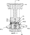
图5是根据本发明的第一装置的第二截面图;Figure 5 is a second sectional view of the first device according to the present invention;
图6是根据本发明的另一装置的前视图。Figure 6 is a front view of another device according to the invention.
具体实施方式 Detailed ways
图1在立体图中示出用来制造螺旋形锥齿轮31的根据本发明的一第一CNC机器20的基本结构。这样一机器20根据本发明可以设计或重新装备,以便能借助于特殊的清理毛刺刀片插入件43.1(见图2)来清理毛刺或倒角锥齿轮31,所述刀片插入件43.1是一清理毛刺的刀片头43的部分,刀片头43通过一安置装置40而可转动。FIG. 1 shows a perspective view of the basic structure of a
CNC机器20可构造如下。一机器外壳26沿着直线坐标轴X(第一轴线)被水平地和直线地导向在机器床身21上。一第一拖板24借助于一螺旋起重致动器21可在导轨10上沿高度移动,导轨10安装在机器外壳26的侧面上,沿一直线坐标轴Z(第二轴线)移动。具有一第二拖板25的工件心轴支承14沿一直线坐标轴Y(第三轴线)在导轨13上被水平地和直线地导向,直线坐标轴Y(第三轴线)垂直于X轴,第二拖板25位于导轨13上。具有一垂直轴C(第四轴线)的枢转装置28位于拖板25上。第一拖板24的导轨10和Z轴倾斜于垂直线。The
第一拖板24承载一工具心轴12,其安装成围绕一工具心轴轴线23(第五轴线)转动。工具心轴12承载一工具,在此情形中,例如,它是一具有若干切割刀片的刀具头22。一工件心轴30通过第二拖板25和通过第一枢转装置28沿水平方向导向和线性位移或在机器床身21上枢转。第一枢转装置28承载工件心轴30,它围绕工件心轴轴线32(第六轴线)可转动。工件心轴30承载一工件31,在本实例中它是一螺旋齿的锥形小齿轮。第一枢转装置28水平地导向围绕C轴可枢转,以便将工件31枢转到一加工位置。此外,设置一安置装置,以便根据本发明能执行一相对的枢转和/或在清理毛刺刀片头43和工件31之间的设定运动。该第二安置装置在图1中不可见。上述枢转和/或设定运动用来使清理毛刺刀片头43的清理毛刺刀片43.1进入一开始的位置。然后,工件31围绕工件心轴轴线32转动,清理毛刺刀片头43围绕转动轴线E(第七轴线)转动,清理毛刺刀片头43的清理毛刺刀片43.1在锥形小齿轮的预定齿边处在一连续的过程中执行对应的倒角和/或清理毛刺的运动。The
如图1所示,清理毛刺刀片头43的转动轴线E可平行于C轴线走向。但也可提供清理毛刺刀片头43的转动轴线E相对于C轴线成一角度。清理毛刺刀片头43的进一步细节在下面的章节中予以描述。As shown in FIG. 1 , the rotational axis E of the
如果对于第二枢转装置的枢转运动不提供一专用的数字控制,则机器20在所示实例中总共还包括七个数字控制的轴。然而,对此枢转运动较佳地设置一数字控制的轴。然而,还可使用带有其它数量轴的机器,由此机器必须具有至少五个数字控制的轴(对于不连续的工作的程序)。If a dedicated digital control is not provided for the pivoting movement of the second pivoting means, the
根据本发明,为了能在连续的程序中实现清理毛刺,机器最好带有至少六个数字控制的轴。According to the invention, the machine preferably has at least six numerically controlled axes in order to be able to achieve deburring in a continuous process.
然而,其它CNC切齿机也可根据本发明进行重组或装备,由此,具有数字控制的七个或八个轴的机器是首选的。However, other CNC gear cutting machines can also be reconfigured or equipped according to the invention, whereby machines with numerically controlled seven or eight axes are preferred.
还存在这样的可能性:装备一CNC切齿机带有一分离的清理毛刺刀片头,其围绕E轴线转动和沿着平行于F轴线的方向移动(如图6所示)。也可设置一安置装置,以便能相对于工件执行设定和/或枢转运动,由此,清理毛刺刀片头43的清理毛刺刀片43.1进入到合适的开始位置。There is also the possibility of equipping a CNC gear cutting machine with a separate deburring blade head that rotates around the E axis and moves in a direction parallel to the F axis (as shown in Figure 6). A positioning device can also be provided so that a setting and/or pivoting movement can be performed relative to the workpiece, whereby the deburring blade 43.1 of the
如上所述,根据本发明的切齿机20包括一工件心轴30,其接纳与工件心轴轴线32同轴的待加工的锥齿轮31。第一拖板24设置有工具心轴12,以便接纳带有若干个切割刀片的盘形的刀片头22。设置另一个轴线E以便接纳和合适地转动一装置43,根据本发明其带有若干个清理毛刺的刀片43.1。此外,设置一安置装置40以便使清理毛刺刀片头43进入到合适的开始位置。如上所述,切齿机20具有若干个(例如,六个、七个或八个)数字控制的轴,它们通过一编程的控制器进行控制,由此,诸轴线之一形成所述工件心轴30的工件心轴轴线32。另一轴线用作为盘形刀片头22的工具心轴轴线23,而轴线E用作为根据本发明的带有清理毛刺的刀片43.1的装置43的清理毛刺心轴轴线。数字控制的轴这样进行设计和布置:通过调整诸轴中的至少一个轴,包括锥齿轮31的工件心轴30相对于带有清理毛刺的刀片43.1的清理毛刺刀片头43移动,这样,同时围绕工件心轴轴线32转动的清理毛刺的刀片43.1和围绕清理毛刺心轴轴线E转动的带有清理毛刺的刀片43.1的清理毛刺刀片头43,相继地进入齿间的间隙内并相对于锥齿轮31的给定边缘执行倒角或清理毛刺运动。As mentioned above, the
在一特别优选的实施例中,清理毛刺刀片头43围绕清理毛刺心轴轴线E的转动和工件31围绕工件心轴轴线32的转动足以进行倒角和/或清理毛刺。In a particularly preferred embodiment, the rotation of the
根据本发明,对清理毛刺刀片头43的清理毛刺的刀片43.1的切割运动较佳地提供一个或多个专用的数字控制的轴。根据实例如在图2至5中所示,这些NC轴线用来相对于工件31移动清理毛刺刀片头43。清理毛刺刀片头43通过一板41和螺纹孔47旋入到一清理毛刺心轴55(例如见图6)。设置一底板保持器42,其包括用来接纳清理毛刺的刀片43.1的不同元件。清理毛刺刀片头43包括若干个杆形的刀片插入件43.1,它们插入在清理毛刺刀片头43的凹陷内,由此,刀片插入件43.1基本上相对于清理毛刺心轴55的清理毛刺心轴轴线E沿径向定向(如图5中所示)。任何的刀片插入件43.1包括用来对工件31倒角和/或清理毛刺的刀刃。一特别优选的实施例装备有四个刀片插入件43.1,由此,这些刀片插入件43.1彼此相隔90度角布置。代替清理毛刺刀片头43处的凹陷,还可设置不同的安装装置以用来夹紧或固定刀片插入件43.1。According to the invention, one or more dedicated digitally controlled axes are preferably provided for the cutting movement of the deburring blade 43.1 of the
较佳地,清理毛刺刀片头43实施为:可通过松动个别夹紧螺钉45被释放和取出。因此,清理毛刺刀片头43可根据需要不同地进行装备。一实施例提供一夹紧球51和每把刀片插入件43.1的夹紧元件,该实施例特别有利,其中,夹紧元件提供一夹紧螺钉45、一直径较小的球52以及一柱头螺栓53。为了在图4的截面图中可见,柱头螺栓53、球52和夹紧螺钉45在底板保持器42的一孔内一个接一个地排成一行。夹紧球51坐落在刀片插入件43.1和夹紧元件之间。如果现在夹紧螺钉45旋入到底板保持器42的孔内,则球52朝向清理毛刺心轴轴线E移动。由于该移动使夹紧球51下压,从而固定刀片插入件43.1。较佳地,使用一带有内六角孔的固定螺钉作为夹紧螺钉45。Preferably, the
如图2至5所示,具有一模块结构的实施例是优选的。形成圆柱形的底板保持器42在下部包括n个(较佳地,取n=1、2、3、4、5、6)矩形凹陷,它的尺寸设计成刀片插入件43.1的轴的横截面。在图4中,一切口显示为被刀片插入件43.1的矩形刀片轴43.2通过。一环54可推入到底板保持器42的下部上(如图2至4中所示)。环54较佳地具Embodiments having a modular structure, as shown in Figures 2 to 5, are preferred. The
有诸凹陷,它们部分地抓住刀片插入件43.1的周围。There are recesses which partially grip the circumference of the blade insert 43.1.
在另一优选的实施例中,设置一夹紧盖44,它覆盖清理毛刺刀片头43的下部(如图2所示)。夹紧盖44可通过一塞头或夹紧接头连接到底板保持器42。夹紧盖44可包括可让固定夹紧盖44的螺钉进入的四个孔48,夹紧盖44用作刀片插入件43.1的相对元件。在夹紧盖44的中心设置一开口49,以便能放入或旋入一选用的打磨刷的轴。打磨刷的轴然后同轴地坐入清理毛刺心轴轴线E。In another preferred embodiment, a clamping
选择地,清理毛刺刀片头43可以实施为:可固定一调整量规50,例如,如图3和图5所示。在所示实例中,调整量规50位于底板保持器42处的刀片插入件43.1的上方。调整量规50的杆柄50.1准确地形成刀片插入件43.1的末端,它沿径向方向最远离清理毛刺心轴轴线E。调整量规50给予刀片插入件43.1一准确的位置。在刀片插入件43.1通过拧紧夹紧螺钉45而被固定之后,即可移去调整量规50。较佳地,调整量规50用两个销或螺钉固定到底板保持器42。为此目的,可在底板保持器42处的各个刀片插入件43.1上方设置两个孔46。Optionally, the
另一实施例示于图6中。该实施例设置有一安置装置56,以便根据本发明能在清理毛刺刀片头43和工件31(未示出)之间实施对应的枢转和/或设定运动。清理毛刺刀片头43围绕轴线E枢转并平行于轴线F可进行设定(如图6所示)。Another embodiment is shown in FIG. 6 . This embodiment is provided with a mounting
根据本发明,刀片插入件43.1由碳化物、工具钢或陶瓷刀具制成。这是与传统清理毛刺的刀具的显著的差别。在一优选的实施例中采用微颗粒的碳化物,因为刀片插入件43.1的刃口在长时间内能保持锋利并且切削干净利落。According to the invention, the blade insert 43.1 is made of carbide, tool steel or ceramic knives. This is a significant difference from conventional deburring knives. In a preferred embodiment fine-grained carbides are used, since the cutting edge of the insert insert 43.1 remains sharp and cuts cleanly over a long period of time.
刀片插入件43.1在刃口区域精磨抛光,这是特别地有利,由此,刀片插入件43.1较佳地显示所谓的2侧或3侧磨刃。2侧磨刃具有的优点在于其较易于被打磨。可首选3侧磨刃,因为所有三个侧腹可相当自由地选择。It is particularly advantageous that the blade insert 43.1 is ground polished in the region of the cutting edge, whereby the blade insert 43.1 preferably exhibits a so-called 2- or 3-side sharpening. The 2-sided sharpening has the advantage that it is easier to sharpen. A 3-side sharpening may be preferred, since all three flanks can be chosen quite freely.
根据本发明的装置的一个特别的优点在于,可使用由碳化物制成的特别设计的清理毛刺刀片插入件43.1。这些清理毛刺的刀片插入件43.1可做成其显示理想的几何形,特别适于对应锥齿轮的清理毛刺或倒角。此外,如果刃口变钝,则这样的清理毛刺刀片插入件43.1可以相当简单地移去和再次打磨。A particular advantage of the device according to the invention is that specially designed deburring blade inserts 43.1 made of carbide can be used. These deburring blade inserts 43.1 can be made in such a way that they show the desired geometry, which is particularly suitable for deburring or chamfering corresponding bevel gears. Furthermore, such a deburring blade insert 43.1 can be removed and resharpened rather simply if the cutting edge becomes dull.
此外,根据本发明,可取消导致人为差错或时间等待的复杂的再次装配,因为,清理毛刺刀具在机器上不会发生拆卸和安装。Furthermore, according to the invention, complex reassembly, which causes human error or time waiting, can be dispensed with, since the deburring tool does not have to be disassembled and installed on the machine.
由于在连续的程序中使用特殊的刀片插入件43.1,工人可以相对高的切割速度工作,所以,对于切齿机上清理毛刺来说,不会形成相当的时间耽误。根据本实施例,为了完成倒角或清理毛刺,将工件31从工作位置移送到一移去的位置所需要的时间是充分足够的。Due to the use of the special blade insert 43.1 in a continuous procedure, the worker can work at a relatively high cutting speed, so that there is no considerable time delay for deburring on the gear cutting machine. According to the present embodiment, the time required to move the
Claims (11)
Applications Claiming Priority (2)
| Application Number | Priority Date | Filing Date | Title |
|---|---|---|---|
| DE202004008263.2 | 2004-05-19 | ||
| DE202004008263U DE202004008263U1 (en) | 2004-05-19 | 2004-05-19 | Deburring knife, device for receiving deburring knives and bevel gear cutting machine for gripping and / or deburring a bevel gear |
Publications (2)
| Publication Number | Publication Date |
|---|---|
| CN1699005A CN1699005A (en) | 2005-11-23 |
| CN100503112C true CN100503112C (en) | 2009-06-24 |
Family
ID=32864772
Family Applications (1)
| Application Number | Title | Priority Date | Filing Date |
|---|---|---|---|
| CNB2005100712844A Expired - Fee Related CN100503112C (en) | 2004-05-19 | 2005-05-12 | Method for removing burrs, bevel gear cutting machine used therefor |
Country Status (8)
| Country | Link |
|---|---|
| US (1) | US7431544B2 (en) |
| EP (1) | EP1598137B1 (en) |
| JP (1) | JP4448056B2 (en) |
| KR (1) | KR101288727B1 (en) |
| CN (1) | CN100503112C (en) |
| AT (1) | ATE365604T1 (en) |
| DE (2) | DE202004008263U1 (en) |
| ES (1) | ES2287830T3 (en) |
Families Citing this family (34)
| Publication number | Priority date | Publication date | Assignee | Title |
|---|---|---|---|---|
| DE202005011790U1 (en) | 2005-07-22 | 2005-10-20 | Gleason-Pfauter Maschinenfabrik Gmbh | Unit for deburring and creation of chamfer at teeth of bevel wheel, attached to main device for creation of toothed areas |
| US7310863B2 (en) * | 2006-02-10 | 2007-12-25 | Gm Global Technology Operations, Inc. | De-burring apparatus for a hobbing machine |
| DE602007014068D1 (en) * | 2006-09-06 | 2011-06-01 | Gleason Works | |
| US20090041553A1 (en) * | 2007-08-06 | 2009-02-12 | 3M Innovative Properties Company | Fly-cutting system and method, and related tooling and articles |
| EP2480366B1 (en) | 2009-09-25 | 2013-11-06 | The Gleason Works | Apparatus for chamfering and/or deburring of gears |
| US20110116885A1 (en) * | 2009-11-13 | 2011-05-19 | Chunliang Hsiao | Face hob hypoid gear tooth top-land radius by common chamfer tool |
| CN101704136B (en) * | 2009-11-20 | 2011-05-18 | 江苏南方机电股份有限公司 | Working head device of gear end surface profiling chamfering machine |
| CN101941102B (en) * | 2010-08-27 | 2012-01-11 | 西安理工大学 | Displacement analog loading device of form grinding wheel gear grinding machine and method for detecting rigidity distribution |
| SE536294C2 (en) * | 2011-04-08 | 2013-08-06 | Sandvik Intellectual Property | Milling tools designed for hobbing a workpiece |
| US9192998B2 (en) * | 2011-09-15 | 2015-11-24 | The Gleason Works | Method for chamfering bevel gears |
| DE102012010689A1 (en) * | 2012-05-30 | 2013-12-05 | Vollmer Werke Maschinenfabrik Gmbh | Device for sharpening tools with cutting edges, such as drills, milling cutters or the like |
| CN102814555B (en) * | 2012-09-06 | 2014-12-10 | 玉环普天单向器有限公司 | Chamfer angle machining device of starting gear and machining method of starting gear |
| DE102014008475B4 (en) * | 2014-06-05 | 2023-02-23 | Gleason-Pfauter Maschinenfabrik Gmbh | Process for machining a workpiece, tool arrangement and gear cutting machine |
| DE102014014132A1 (en) * | 2014-09-30 | 2016-05-25 | Liebherr-Verzahntechnik Gmbh | Method and device for chamfering and deburring toothed workpieces |
| US10357837B2 (en) * | 2014-12-18 | 2019-07-23 | The Gleason Works | Cutter build and truing machine |
| CN104625242A (en) * | 2015-02-11 | 2015-05-20 | 温岭市宇弘机械设备有限公司 | Numerical control coupling teeth-machining chamfering all-in-one machine |
| EP3120960B1 (en) * | 2015-07-20 | 2023-06-14 | Klingelnberg AG | Method for finishing a bevel gear in the area of the tip, machine for machining bevel gears |
| DE102015121821A1 (en) * | 2015-12-15 | 2017-06-22 | Profilator Gmbh & Co. Kg | Device and method for producing a chamfer on a toothed wheel |
| CN105437000A (en) * | 2015-12-24 | 2016-03-30 | 重庆威诺克智能装备股份有限公司 | Five-shaft cutter grinding machine tool |
| DE102016117962A1 (en) | 2016-09-23 | 2018-03-29 | Klingelnberg Ag | Bevel gear cutting machine for chamfering bevel gear tooth edges and method for chamfering the tooth edges of bevel gears |
| DE102017105032B4 (en) * | 2017-03-09 | 2018-09-20 | Präwema Antriebstechnik GmbH | Tool, machine and method for producing roof ridge-like tipping on teeth of an internally and externally toothed gear |
| KR101938967B1 (en) * | 2017-03-24 | 2019-01-16 | 현대위아 주식회사 | 5-axis machining center |
| DE102017107999A1 (en) | 2017-04-13 | 2018-10-18 | Klingelnberg Ag | Deburring device and CNC gear cutting machine with such a deburring device |
| KR20190084538A (en) | 2018-01-08 | 2019-07-17 | 양범철 | Apparatus for rounding edge of synthetic resin tile and method thereof |
| EP3517235B1 (en) | 2018-01-25 | 2020-12-09 | Klingelnberg GmbH | Method for deburring bevel wheels and cnc machine with a corresponding software for deburring |
| DE102018108622A1 (en) * | 2018-04-11 | 2019-10-17 | Liebherr-Verzahntechnik Gmbh | Device for chamfering a workpiece |
| DE102018131538A1 (en) * | 2018-12-10 | 2020-06-10 | Schaeffler Technologies AG & Co. KG | Tool for performing a deburring process, deburring process and the component formed with it, as well as a gear cutting machine |
| CN109877396A (en) * | 2019-02-26 | 2019-06-14 | 第一拖拉机股份有限公司 | A kind of spiral bevel gear tooth top tip relief method |
| CN112338294B (en) * | 2020-09-30 | 2021-12-07 | 宁波夏拓智能科技有限公司 | Online deburring device for gear hobbing machine |
| CN112847968A (en) * | 2021-01-11 | 2021-05-28 | 程文喜 | Loss correction type plastic gear processing device |
| CN113211314B (en) * | 2021-05-07 | 2022-04-22 | 沈阳华钛实业有限公司 | Angle-adjustable clamping device for machining blisk and using method thereof |
| DE102022004131A1 (en) * | 2022-11-07 | 2024-05-08 | Gleason-Pfauter Maschinenfabrik Gmbh | METHOD FOR GEAR MACHINING WITH SUBSEQUENT CHAMFERING |
| CN115592445B (en) * | 2022-12-08 | 2023-04-07 | 泰州市现代数控机械有限公司 | Four-axis machining equipment capable of automatically positioning materials and changing tools |
| WO2025193898A1 (en) * | 2024-03-14 | 2025-09-18 | The Gleason Works | Method and device for deburring toothed articles |
Citations (6)
| Publication number | Priority date | Publication date | Assignee | Title |
|---|---|---|---|---|
| US1626821A (en) * | 1923-09-12 | 1927-05-03 | Gleason Works | Method and machine for cutting gears |
| US3036363A (en) * | 1957-06-05 | 1962-05-29 | Manchester Machine & Tool Comp | Face mill cutter |
| US4697963A (en) * | 1985-02-08 | 1987-10-06 | Ingersoll Cutting Tool Company | Insert clamping device and insert therefor |
| DE19744486A1 (en) * | 1997-10-09 | 1999-04-29 | Mhd Maschinenservice Gmbh | Machine for deburring and relieving the ends of angled or curved bevel and spur gear teeth |
| US6632050B2 (en) * | 2001-09-06 | 2003-10-14 | Kennametal Inc. | Face hobbing cutter |
| US20030210964A1 (en) * | 2002-03-27 | 2003-11-13 | Fitzgerald Brian M. | Combination gear hobber, chamfer/debur and shaver apparatus and method |
Family Cites Families (13)
| Publication number | Priority date | Publication date | Assignee | Title |
|---|---|---|---|---|
| US1836662A (en) * | 1929-01-22 | 1931-12-15 | Gleason Works | Cutter truing device |
| US2135819A (en) * | 1936-09-15 | 1938-11-08 | W C Lipe Inc | Adjustable chamfering tool and holder |
| US2772602A (en) * | 1951-03-30 | 1956-12-04 | John M Christman | Apparatus for manufacturing spiral bevel and hypoid gears |
| US3286593A (en) * | 1964-12-15 | 1966-11-22 | William H Bibbens | Method and apparatus for chamfering toothed machine elements |
| JPS58160017A (en) * | 1982-03-16 | 1983-09-22 | Osaka Seibu Eng Kk | Gear tooth chamfering device |
| US4784537A (en) * | 1987-01-05 | 1988-11-15 | Gte Valeron Corporation | Multiple tooth thread milling apparatus |
| JPS6451223A (en) * | 1987-08-21 | 1989-02-27 | Aisin Houyou Kk | Toothed wheel chamfering device |
| JP3017503B2 (en) * | 1989-04-28 | 2000-03-13 | トヨタ自動車株式会社 | Universal gear chamfering machine |
| JP2578569B2 (en) * | 1993-06-30 | 1997-02-05 | 豊精密工業株式会社 | Chamfering method for spiral bevel gears |
| USRE38504E1 (en) * | 1996-11-08 | 2004-04-20 | Klingelnberg Gmbh | Machine for producing spiral-toothed bevel gears |
| DE19708601A1 (en) * | 1997-03-03 | 1998-09-10 | Maier Kg Andreas | Adjustable blade for cutting cylinder |
| DE19902035A1 (en) * | 1999-01-20 | 2000-07-27 | Werner Hermann Wera Werke | Method and device for chamfering the front edges of the tooth grooves of toothed workpieces |
| JP2002254244A (en) | 2001-03-02 | 2002-09-10 | Yutaka Seimitsu Kogyo Ltd | Deburring tool, bevel gear deburring method and apparatus |
-
2004
- 2004-05-19 DE DE202004008263U patent/DE202004008263U1/en not_active Expired - Lifetime
-
2005
- 2005-04-16 AT AT05008339T patent/ATE365604T1/en active
- 2005-04-16 DE DE502005000917T patent/DE502005000917D1/en not_active Expired - Lifetime
- 2005-04-16 ES ES05008339T patent/ES2287830T3/en not_active Expired - Lifetime
- 2005-04-16 EP EP05008339A patent/EP1598137B1/en not_active Expired - Lifetime
- 2005-05-02 KR KR1020050036769A patent/KR101288727B1/en not_active Expired - Fee Related
- 2005-05-12 CN CNB2005100712844A patent/CN100503112C/en not_active Expired - Fee Related
- 2005-05-12 US US11/129,276 patent/US7431544B2/en active Active
- 2005-05-17 JP JP2005144119A patent/JP4448056B2/en not_active Expired - Fee Related
Patent Citations (6)
| Publication number | Priority date | Publication date | Assignee | Title |
|---|---|---|---|---|
| US1626821A (en) * | 1923-09-12 | 1927-05-03 | Gleason Works | Method and machine for cutting gears |
| US3036363A (en) * | 1957-06-05 | 1962-05-29 | Manchester Machine & Tool Comp | Face mill cutter |
| US4697963A (en) * | 1985-02-08 | 1987-10-06 | Ingersoll Cutting Tool Company | Insert clamping device and insert therefor |
| DE19744486A1 (en) * | 1997-10-09 | 1999-04-29 | Mhd Maschinenservice Gmbh | Machine for deburring and relieving the ends of angled or curved bevel and spur gear teeth |
| US6632050B2 (en) * | 2001-09-06 | 2003-10-14 | Kennametal Inc. | Face hobbing cutter |
| US20030210964A1 (en) * | 2002-03-27 | 2003-11-13 | Fitzgerald Brian M. | Combination gear hobber, chamfer/debur and shaver apparatus and method |
Also Published As
| Publication number | Publication date |
|---|---|
| EP1598137B1 (en) | 2007-06-27 |
| ATE365604T1 (en) | 2007-07-15 |
| JP2005329536A (en) | 2005-12-02 |
| DE202004008263U1 (en) | 2004-08-12 |
| ES2287830T3 (en) | 2007-12-16 |
| JP4448056B2 (en) | 2010-04-07 |
| DE502005000917D1 (en) | 2007-08-09 |
| CN1699005A (en) | 2005-11-23 |
| US20050260050A1 (en) | 2005-11-24 |
| KR20060047686A (en) | 2006-05-18 |
| US7431544B2 (en) | 2008-10-07 |
| KR101288727B1 (en) | 2013-07-23 |
| EP1598137A1 (en) | 2005-11-23 |
Similar Documents
| Publication | Publication Date | Title |
|---|---|---|
| CN100503112C (en) | Method for removing burrs, bevel gear cutting machine used therefor | |
| KR101746078B1 (en) | Machine tool and method for producing gearing | |
| JP7343513B2 (en) | Chamfering tools, chamfering systems, gear cutting machines and methods for chamfering gears | |
| JP7224399B2 (en) | Work chamfering device, gear machining center equipped with same, and machining method using work chamfering device | |
| CN107866612B (en) | Bevel gear cutting machine and method for chamfering the edges of a bevel gear | |
| JP6012705B2 (en) | How to make teeth on a workpiece | |
| US7794186B2 (en) | Gear cutting machine, in particular bevel gear cutting machine, having a device for chamfering / deburring the edges of a work piece | |
| CN100542724C (en) | Bevel gear cutting machines for chamfering and/or deburring bevel gear teeth | |
| EP2861376B1 (en) | Grinding machine with multi-spindle grinding head | |
| CN115916443B (en) | Equipment and methods for forming chamfers on the tooth surface of gears, as well as cutting tools, inserts and control programs for this purpose. | |
| JPH06510242A (en) | Method and apparatus for machining spur and helical gears | |
| CN100525975C (en) | Method and machine for grinding tooth side of rotary gear | |
| EP2516092B1 (en) | Method and apparatus for manufacturing bevel gears | |
| CN112203789B (en) | Multi-tool chamfering device for toothed workpieces | |
| JP3903717B2 (en) | Tapered hole machining method and tapered hole machining tool | |
| JP3138053U (en) | Shaping device for grinding surface of grinding wheel for gear grinding | |
| JP2005081472A (en) | Shaping method of grinding surface of grinding wheel for grinding gear | |
| WO2004060596A1 (en) | Contour plunge milling | |
| JP2008126358A (en) | Cutting apparatus and cutting method | |
| WO2024009520A1 (en) | Cutting blade tool and method of producing cutting blade |
Legal Events
| Date | Code | Title | Description |
|---|---|---|---|
| C06 | Publication | ||
| PB01 | Publication | ||
| C10 | Entry into substantive examination | ||
| SE01 | Entry into force of request for substantive examination | ||
| C14 | Grant of patent or utility model | ||
| GR01 | Patent grant | ||
| CF01 | Termination of patent right due to non-payment of annual fee |
Granted publication date: 20090624 |
|
| CF01 | Termination of patent right due to non-payment of annual fee |